EP3556712B1 - Sicherheitssystem - Google Patents
Sicherheitssystem Download PDFInfo
- Publication number
- EP3556712B1 EP3556712B1 EP18168520.7A EP18168520A EP3556712B1 EP 3556712 B1 EP3556712 B1 EP 3556712B1 EP 18168520 A EP18168520 A EP 18168520A EP 3556712 B1 EP3556712 B1 EP 3556712B1
- Authority
- EP
- European Patent Office
- Prior art keywords
- safety
- space
- controller
- safety space
- working equipment
- Prior art date
- Legal status (The legal status is an assumption and is not a legal conclusion. Google has not performed a legal analysis and makes no representation as to the accuracy of the status listed.)
- Active
Links
Images


Classifications
-
- B—PERFORMING OPERATIONS; TRANSPORTING
- B66—HOISTING; LIFTING; HAULING
- B66C—CRANES; LOAD-ENGAGING ELEMENTS OR DEVICES FOR CRANES, CAPSTANS, WINCHES, OR TACKLES
- B66C13/00—Other constructional features or details
- B66C13/18—Control systems or devices
- B66C13/46—Position indicators for suspended loads or for crane elements
-
- B—PERFORMING OPERATIONS; TRANSPORTING
- B60—VEHICLES IN GENERAL
- B60P—VEHICLES ADAPTED FOR LOAD TRANSPORTATION OR TO TRANSPORT, TO CARRY, OR TO COMPRISE SPECIAL LOADS OR OBJECTS
- B60P1/00—Vehicles predominantly for transporting loads and modified to facilitate loading, consolidating the load, or unloading
- B60P1/54—Vehicles predominantly for transporting loads and modified to facilitate loading, consolidating the load, or unloading using cranes for self-loading or self-unloading
-
- B—PERFORMING OPERATIONS; TRANSPORTING
- B66—HOISTING; LIFTING; HAULING
- B66C—CRANES; LOAD-ENGAGING ELEMENTS OR DEVICES FOR CRANES, CAPSTANS, WINCHES, OR TACKLES
- B66C13/00—Other constructional features or details
- B66C13/18—Control systems or devices
-
- B—PERFORMING OPERATIONS; TRANSPORTING
- B66—HOISTING; LIFTING; HAULING
- B66C—CRANES; LOAD-ENGAGING ELEMENTS OR DEVICES FOR CRANES, CAPSTANS, WINCHES, OR TACKLES
- B66C13/00—Other constructional features or details
- B66C13/18—Control systems or devices
- B66C13/40—Applications of devices for transmitting control pulses; Applications of remote control devices
-
- B—PERFORMING OPERATIONS; TRANSPORTING
- B66—HOISTING; LIFTING; HAULING
- B66C—CRANES; LOAD-ENGAGING ELEMENTS OR DEVICES FOR CRANES, CAPSTANS, WINCHES, OR TACKLES
- B66C15/00—Safety gear
- B66C15/04—Safety gear for preventing collisions, e.g. between cranes or trolleys operating on the same track
- B66C15/045—Safety gear for preventing collisions, e.g. between cranes or trolleys operating on the same track electrical
-
- B—PERFORMING OPERATIONS; TRANSPORTING
- B66—HOISTING; LIFTING; HAULING
- B66C—CRANES; LOAD-ENGAGING ELEMENTS OR DEVICES FOR CRANES, CAPSTANS, WINCHES, OR TACKLES
- B66C23/00—Cranes comprising essentially a beam, boom, or triangular structure acting as a cantilever and mounted for translatory of swinging movements in vertical or horizontal planes or a combination of such movements, e.g. jib-cranes, derricks, tower cranes
- B66C23/88—Safety gear
- B66C23/90—Devices for indicating or limiting lifting moment
- B66C23/905—Devices for indicating or limiting lifting moment electrical
-
- B—PERFORMING OPERATIONS; TRANSPORTING
- B66—HOISTING; LIFTING; HAULING
- B66C—CRANES; LOAD-ENGAGING ELEMENTS OR DEVICES FOR CRANES, CAPSTANS, WINCHES, OR TACKLES
- B66C2700/00—Cranes
- B66C2700/08—Electrical assemblies or electrical control devices for cranes, winches, capstans or electrical hoists
- B66C2700/082—Control of the secondary movements, e.g. travelling, slewing, luffing of the jib, changing of the range
Definitions
- the present disclosure relates to a safety system for a vehicle provided with a working equipment, e.g. a crane, and in particular a safety system where various safety spaces in relation to the vehicle are presented to a user on a display unit.
- the disclosure also relates to a method in relation to a safety system.
- a working equipment for a working vehicle may comprise a crane often provided with extendible arms and normally having a working tool arranged at a crane tip.
- An operator of the working equipment normally controls e.g. the crane via a remote controller.
- high demands are required on the operator in order to safely load or unload a load taking into account various environmental obstacles, e.g. overhead electric cables, bridges, buildings, etc.
- EP2323943 discloses a safety system for a vehicle provided with stabilizer legs which are controlled by means of a remote control unit.
- Two transmitting units are arranged on each stabilizer leg in order to communicate with a receiving unit provided on the remote control unit.
- the transmitting ranges of the transmitting units are different to thereby enable the transmitting units to define an inner zone boundary and an outer zone boundary.
- the remote control unit is only allowed to control the movement of a stabilizer leg when it is established, based on the signals received from the transmitting units, that the remote control unit is located in the region between the inner zone boundary and the outer zone boundary.
- US 9269255 discloses a worksite proximity warning system. Personnel or objects at the worksite may be equipped with transceivers and a virtual safety envelop is created around each transceiver. When two of the virtual safety envelopes enters in contact with each other, warnings or alarms may warn the personnel of potential hazards.
- WO 2013/007329 discloses a remote control system for controlling a self-propelled implement, wherein a remote control unit is provided with means for sending an electromagnetic safety signal with a limited transmitting range.
- the electromagnetic safety signal defines a safety area around the remote control unit and the movement of the self-propelled implement is stopped when a receiver on the self-propelled implement receives the electromagnetic safety signal.
- US-5490081 discloses a system for limiting the operation range of a working tool of a working machine, such as for instance a hydraulic excavator, wherein the operator may set the boundary of a safety region in order to prevent the working tool from interfering with the operator's station.
- US 4833615 discloses a system for defining boundaries for the allowable working area of a crane, wherein the crane is moved by the crane operator to positions corresponding to the desired boundaries and these positions are recorded in order to define the boundaries.
- DE 4331776 discloses a system where the allowable working area of a crane is defined by different boundary lines. However, it is not described how the positions for these boundary lines are set.
- CN 104098032 discloses a system where an operator of a crane may input numerical values in order to define desired boundaries for an allowable working area of the crane.
- WO-2013/006625 relates to a system for tracking moveable crane components to assist maneuvering the crane within a jobsite.
- This document discloses the preamble parts of the independent claims 1 and 8.
- the above patent documents show that many different safety solutions exist intended to provide and monitor safety zones for operators of e.g. a crane. However, there are still room for further improvements in order to further improve the safety and also to improve the user-friendliness when working in relation to working vehicles provided with a working equipment, e.g. a crane.
- the object of the present invention is to achieve an improved safety system that meets high safety requirements and at the same time being user-friendly and easy to use.
- the present invention relates to a safety system for a working vehicle comprising a working equipment, e.g. a crane or a working tool
- the safety system comprises a control unit, a controller, e.g. a remote controller, configured to control said working equipment, and a display unit.
- the control unit is configured to:
- the present invention relates to a method in relation to a safety system for a working vehicle comprising a working equipment, e.g. a crane or a working tool
- the safety system comprises a control unit, a controller, e.g. a remote controller, configured to control said working equipment, and a display unit.
- the method comprises:
- the safety system and also the method in relation to the system according to the present invention improves the safety and user-friendliness when working with a working equipment by presenting available safety spaces to an operator that may choose and adapt a safety space to a particular situation.
- a safety system 2 for a working vehicle 4 comprising a working equipment 6, e.g. a crane or a working tool, will be described in detail.
- the working vehicle may e.g. be a cargo vehicle provided with a crane, a working vehicle provided with a crane having a rotator arranged at the crane tip, or any other vehicle provided with any type of working equipment.
- the safety system 2 comprises a control unit 8, a controller 10, e.g. a remote controller, configured to control the working equipment 6 by a control signal 11, and a display unit 12.
- the display unit may be an integrated part of the controller.
- the control unit is provided with a necessary processing capability in order to perform all processing and calculations required herein, and may be a separate unit arranged within the vehicle or a unit being an integrated part of the vehicle's other control units.
- the control unit is configured to define a set of three-dimensional safety spaces 14 (see figure 2 ) in relation to the vehicle 4, wherein each safety space 14 is defined by a data representation of boundaries 16 of the safety space 14.
- the data representation of the boundaries of the set of three-dimensional safety spaces may e.g. be stored in a memory unit of the control unit.
- a 3D safety space may be regarded as a virtual 3D safety cage having delimitation surfaces between the boundaries.
- the control unit is further configured to present at least one safety space 14 from the set of safety spaces on the display unit 12, wherein the at least one safety space being presented overlaid on an image 18 of at least a part of the working vehicle 4 and working equipment 6.
- the image 18 may be obtained by one or many cameras arranged at the vehicle and/or working equipment, or may be schematic images of the vehicle and working equipment.
- Each presented safety space being presented in a predefined position, defined by space position parameters, in relation to the working vehicle and working equipment.
- An operator of the vehicle may then determine one or many of the safety spaces presented at the display unit to be chosen. This may be performed by touching the chosen safety space if the display unit is a touch screen, or by selecting the safety space by moving a cursor on the screen and mark the chosen safety space(s).
- a first input signal 20 is generated and the control unit 8 is configured to receive the first input signal 20 comprising space position parameters representing at least one chosen safety space among the presented safety spaces, and to designate each at least one chosen safety space as an active safety space 14A (see figure 3 ).
- control unit is configured to receive a second input signal 22 comprising a safety space state command either allowing or preventing the working equipment to be moved into the at least one active safety space 14A.
- This second input signal may be manually generated by the operator via the controller.
- the signal may be automatically generated to be a state ("allow” or "prevent") set when initiating the system.
- the control unit 8 is then configured to apply a state command signal 24 to the controller 10 that in turn is configured to control the working equipment 6 in dependence of the safety space state command by applying the control signal 11 to the working equipment 6, i.e. such that the working equipment is prevented or allowed to move into the active safety space(s).
- a safety space preferably set up for preventing the working equipment from moving into the safety space, is determined to a location where the operator stands, and often the operator controls the working equipment by a controller, preferably a remote controller.
- one of the safety spaces 14 in the set of safety spaces is determined to be a space around the controller 10.
- the size of the safety space is such that the operator is safely within the safety space.
- the safety space being e.g. a circular cylinder around the operator having a radius of 1 m. and a height of 2.5 m.
- the controller 10 comprises a positioning member 26, e.g. working according to the Global Positioning System (GPS) technology, configured to determine the position of the controller and to generate a positioning signal 28 to the control unit, and that the safety space 14 is determined, by the control unit 8, in dependence of the determined position of the controller.
- GPS Global Positioning System
- control unit 8 is configured to disable the controller 10 when the controller is not in an active safety space. By disabling the controller no control of the working equipment may be performed by the controller. This may be performed directly, or after a specified delay, or after a warning has been generated to the operator to notify the operator that the controller will be disabled. This embodiment is advantageous if the operators move when controlling the working equipment.
- control unit 8 is configured to enable the controller 10 when the controller is detected to be in an active safety space.
- FIG 3 is illustrated the display unit presenting an image of the working vehicle and the working equipment 6, illustrating an embodiment where the control unit is configured to present the at least one active safety space 14A in the determined position(s) on said display unit 12, and to stop presenting the not chosen safety space(s).
- two active safety spaces 14A are shown. One around the working equipment 6, and one where an operator may be located.
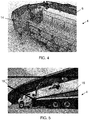
- figure 4 is illustrated an example where safety spaces 14 are presented overlaid on an image of the vehicle in relation to support legs of the vehicle.
- the set of safety spaces may be predefined and determined to be in predefined positions in relation to the vehicle, working equipment, and controller.
- the boundaries 16 of the safety spaces may be defined by the operator, e.g. in dependence of the location of the vehicle where obstacles, e.g. bridges, may set limits for the movements of the working equipment.
- FIG 5 Such a situation is illustrated in figure 5 where boundaries 16 to the safety space is set by an operator in relation to the environment, in this example a bridge.
- the safety state command is "allow", i.e. the working equipment 6 is allowed to move within the safety space, but not outside.
- control unit 8 is configured to receive boundary signals 30 representing positions of the boundaries 16 of a safety space 14, wherein the boundary signals 30 are obtained during a safety space set-up procedure, and obtained when defining a set of three-dimensional safety spaces 14.
- the operator may move a safety space presented at the display, being a touch screen, by choosing (touching) and dragging the presented safety space to a desired location, e.g. a location that is safe to stand when controlling the working equipment. It may then also be possible to the change size of a presented safety space, e.g. by using two fingers and increasing or decreasing the distance between the finger tips touching the screen.
- the boundary signals 28 are generated during movement of the working equipment 6 and in dependence of positions of the working equipment. This is achieved by moving the working equipment, e.g. the crane, such that the crane tip is moved to various positions that are registered and then stored and applied as boundaries for safety spaces.
- the present invention also relates to a method in relation to a safety system 2 for a working vehicle 4 comprising a working equipment 6, e.g. a crane or a working tool.
- a working equipment 6 e.g. a crane or a working tool.
- the safety system 2 has been described in detail above and it is herein referred to that description.
- the safety system comprises a control unit 8, a controller 10, e.g. a remote controller, configured to control the working equipment 6, and a display unit 12.
- the method comprises the steps of:
- the method comprises defining one of the safety spaces 14 in said set of safety spaces around the controller 10. In a further embodiment the method comprises disabling the controller 10 when the controller is not in an active safety space, and enabling the controller 10 when the controller is in an active safety space.
- the method comprises presenting the at least one active safety space 14A in the determined position(s) on the display unit 12, and to stop presenting the not chosen safety space(s).
- the method then comprises receiving boundary signals 30, e.g. generated by the operator, representing positions of the boundaries 16 of a safety space 14, and that the boundary signals 30 are obtained during a safety space set-up procedure, and obtained when defining a set of three-dimensional safety spaces 14.
- the method comprises generating the boundary signals 30 when moving the working equipment 6 to various positions in order to define the boundaries of the safety space, e.g. by detecting the positions of a working equipment, e.g. of a crane tip.
- the boundaries of the safety spaces may be easily adapted to a specific environment.
Landscapes
- Engineering & Computer Science (AREA)
- Mechanical Engineering (AREA)
- Automation & Control Theory (AREA)
- Transportation (AREA)
- Forklifts And Lifting Vehicles (AREA)
Claims (12)
- Sicherheitssystem (2) für ein Arbeitsfahrzeug (4), aufweisend ein Arbeitsgerät (6), z.B. einen Kran oder ein Arbeitswerkzeug, wobei das Sicherheitssystem (2) eine Steuereinheit (8), eine Steuereinrichtung (10), z.B. eine Fernsteuerung, die dafür ausgelegt ist, das Arbeitsgerät (6) zu steuern, und eine Anzeigeeinheit (12) aufweist, wobei die Steuereinheit dafür ausgelegt ist:- einen Satz von dreidimensionalen Sicherheitsräumen (14) in Bezug auf das Fahrzeug (4) zu definieren, wobei jeder Sicherheitsraum (14) durch eine Datendarstellung von Grenzen (16) des Sicherheitsraums definiert wird, wobei sich einer der Sicherheitsräume (14) in dem Satz von Sicherheitsräumen um die Steuereinrichtung (10) befindet,- wenigstens einen Sicherheitsraum (14) aus dem Satz von Sicherheitsräumen auf der Anzeigeeinheit (12) darzustellen,dadurch gekennzeichnet, dass der wenigstens eine Sicherheitsraum über ein Bild (18) wenigstens eines Teils des Arbeitsfahrzeugs (4) und des Arbeitsgeräts (6) gelagert dargestellt wird, und wobei jeder dargestellte Sicherheitsraum in einer durch Raumpositionsparameter definierten Position in Bezug auf das Arbeitsfahrzeug und das Arbeitsgerät dargestellt wird, und wobei die Steuereinheit ferner dafür ausgelegt ist:- ein erstes Eingangssignal (20) zu empfangen, das Raumpositionsparameter umfasst, die wenigstens einen ausgewählten Sicherheitsraum unter den dargestellten Sicherheitsräumen repräsentieren, und jeden wenigstens einen ausgewählten Sicherheitsraum als aktiven Sicherheitsraum (14A) zu bezeichnen, und- ein zweites Eingangssignal (22) zu empfangen, das einen Sicherheitsraumzustandsbefehl umfasst, der entweder erlaubt oder verhindert, dass das Arbeitsgerät in den wenigstens einen aktiven Sicherheitsraum (14A) bewegt wird, und ein Zustandsbefehlssignal (24) an die Steuereinrichtung (10) anzulegen, die ihrerseits dafür ausgelegt ist, das Arbeitsgerät (6) in Abhängigkeit von dem Sicherheitsraumzustandsbefehl zu steuern.
- Sicherheitssystem (2) nach Anspruch 1, wobei die Steuereinrichtung (10) ein Positionierungselement (26) aufweist, das dafür ausgelegt ist, die Position der Steuereinrichtung zu bestimmen, und wobei der Sicherheitsraum (14) durch die Steuereinheit (8) in Abhängigkeit von der bestimmten Position der Steuereinrichtung bestimmt wird.
- Sicherheitssystem (2) nach einem der Ansprüche 1 bis 2, wobei die Steuereinheit (8) dafür ausgelegt ist, die Steuereinrichtung (10) zu deaktivieren, wenn sich die Steuereinrichtung nicht in einem aktiven Sicherheitsraum befindet.
- Sicherheitssystem (2) nach einem der Ansprüche 1 bis 3, wobei die Steuereinheit (8) dafür ausgelegt ist, die Steuereinrichtung (10) zu aktivieren, wenn sich die Steuereinrichtung in einem aktiven Sicherheitsraum befindet.
- Sicherheitssystem (2) nach einem der Ansprüche 1 bis 4, wobei die Steuereinheit (8) ferner dafür ausgelegt ist, den wenigstens einen aktiven Sicherheitsraum (14A) in der (den) bestimmten Position(en) auf der Anzeigeeinheit (12) darzustellen und die Darstellung des (der) nicht ausgewählten Sicherheitsraums (Sicherheitsräume) zu beenden.
- Sicherheitssystem (2) nach einem der Ansprüche 1 bis 5, wobei die Steuereinheit (8) dafür ausgelegt ist, Grenzsignale (30) zu empfangen, die Positionen der Grenzen (16) eines Sicherheitsraums (14) repräsentieren, wobei die Grenzsignale (28) während eines Vorgangs der Einrichtung eines Sicherheitsraums erhalten werden und erhalten werden, wenn ein Satz von dreidimensionalen Sicherheitsräumen (14) definiert wird.
- Sicherheitssystem (2) nach Anspruch 6, wobei die Grenzsignale (28) während der Bewegung des Arbeitsgeräts (6) und in Abhängigkeit von Positionen des Arbeitsgeräts generiert werden.
- Verfahren im Zusammenhang mit einem Sicherheitssystem (2) für ein Arbeitsfahrzeug (4), aufweisend ein Arbeitsgerät (6), z.B. einen Kran oder ein Arbeitswerkzeug, wobei das Sicherheitssystem (2) eine Steuereinheit (8), eine Steuereinrichtung (10), z.B. eine Fernsteuerung, die dafür ausgelegt ist, das Arbeitsgerät (6) zu steuern, und eine Anzeigeeinheit (12) aufweist, wobei das Verfahren Folgendes umfasst:- Definieren eines Satzes von dreidimensionalen Sicherheitsräumen (14) in Bezug auf das Fahrzeug (4), wobei jeder Sicherheitsraum (14) durch eine Datendarstellung von Grenzen (16) des Sicherheitsraums definiert wird, wobei sich einer der Sicherheitsräume (14) in dem Satz von Sicherheitsräumen um die Steuereinrichtung (10) befindet,- Darstellen wenigstens eines Sicherheitsraums (14) aus dem Satz von Sicherheitsräumen auf der Anzeigeeinheit (12), dadurch gekennzeichnet, dass der wenigstens eine Sicherheitsraum über ein Bild (18) wenigstens eines Teils des Arbeitsfahrzeugs (4) und des Arbeitsgeräts (6) gelagert dargestellt wird, und wobei jeder dargestellte Sicherheitsraum in einer durch Raumpositionsparameter definierten Position in Bezug auf das Arbeitsfahrzeug und das Arbeitsgerät dargestellt wird, und wobei das Verfahren ferner Folgendes umfasst:- Empfangen eines ersten Eingangssignals (20), das Raumpositionsparameter umfasst, die wenigstens einen ausgewählten Sicherheitsraum unter den dargestellten Sicherheitsräumen repräsentieren, und Bezeichnen jedes wenigstens einen ausgewählten Sicherheitsraums als aktiven Sicherheitsraum (14A), und- Empfangen eines zweiten Eingangssignals (22), das einen Sicherheitsraumzustandsbefehl umfasst, der entweder erlaubt oder verhindert, dass das Arbeitsgerät in den wenigstens einen aktiven Sicherheitsraum (14A) bewegt wird, und Anlegen eines Zustandsbefehlssignals (24) an die Steuereinrichtung (10), die ihrerseits das Arbeitsgerät (6) in Abhängigkeit von dem Sicherheitsraumzustandsbefehl steuert.
- Verfahren nach Anspruch 8, umfassend das Deaktivieren der Steuereinrichtung (10), wenn sich die Steuereinrichtung nicht in einem aktiven Sicherheitsraum befindet, und das Aktivieren der Steuereinrichtung (10), wenn sich die Steuereinrichtung in einem aktiven Sicherheitsraum befindet.
- Verfahren nach einem der Ansprüche 8 bis 9, umfassend das Darstellen des wenigstens einen aktiven Sicherheitsraums (14A) in der (den) bestimmten Position(en) auf der Anzeigeeinheit (12) und das Beenden der Darstellung des (der) nicht ausgewählten Sicherheitsraums (Sicherheitsräume).
- Verfahren nach einem der Ansprüche 8 bis 10, umfassend das Empfangen von Grenzsignalen (30), die Positionen der Grenzen (16) eines Sicherheitsraums (14) repräsentieren, wobei die Grenzsignale (30) während eines Vorgangs der Einrichtung eines Sicherheitsraums erhalten werden und erhalten werden, wenn ein Satz von dreidimensionalen Sicherheitsräumen (14) definiert wird.
- Verfahren nach Anspruch 11, umfassend das Generieren der Grenzsignale (30) während der Bewegung des Arbeitsgeräts (6) und in Abhängigkeit von Positionen des Arbeitsgeräts.
Priority Applications (4)
| Application Number | Priority Date | Filing Date | Title |
|---|---|---|---|
| DK18168520.7T DK3556712T3 (da) | 2018-04-20 | 2018-04-20 | Sikkerhedssystem |
| EP18168520.7A EP3556712B1 (de) | 2018-04-20 | 2018-04-20 | Sicherheitssystem |
| AU2019200501A AU2019200501B2 (en) | 2018-04-20 | 2019-01-25 | Safety system |
| US16/386,549 US11649146B2 (en) | 2018-04-20 | 2019-04-17 | Safety system |
Applications Claiming Priority (1)
| Application Number | Priority Date | Filing Date | Title |
|---|---|---|---|
| EP18168520.7A EP3556712B1 (de) | 2018-04-20 | 2018-04-20 | Sicherheitssystem |
Publications (2)
| Publication Number | Publication Date |
|---|---|
| EP3556712A1 EP3556712A1 (de) | 2019-10-23 |
| EP3556712B1 true EP3556712B1 (de) | 2021-06-30 |
Family
ID=62044579
Family Applications (1)
| Application Number | Title | Priority Date | Filing Date |
|---|---|---|---|
| EP18168520.7A Active EP3556712B1 (de) | 2018-04-20 | 2018-04-20 | Sicherheitssystem |
Country Status (4)
| Country | Link |
|---|---|
| US (1) | US11649146B2 (de) |
| EP (1) | EP3556712B1 (de) |
| AU (1) | AU2019200501B2 (de) |
| DK (1) | DK3556712T3 (de) |
Cited By (2)
| Publication number | Priority date | Publication date | Assignee | Title |
|---|---|---|---|---|
| EP4714887A1 (de) | 2024-09-19 | 2026-03-25 | Hiab AB | Krananordnung |
| EP4714888A1 (de) | 2024-09-19 | 2026-03-25 | Hiab AB | Krananordnung |
Families Citing this family (4)
| Publication number | Priority date | Publication date | Assignee | Title |
|---|---|---|---|---|
| DE102019108689A1 (de) * | 2019-04-03 | 2020-10-08 | Liebherr-Werk Biberach Gmbh | Verfahren und Vorrichtung zum Steuern einer Materialumschlags- und/oder Baumaschine |
| JP7271475B2 (ja) * | 2020-06-23 | 2023-05-11 | 三菱重工業株式会社 | 制御システム、クレーン設備、制御方法、及びプログラム |
| DE102021118081B4 (de) * | 2021-07-13 | 2023-02-09 | Thomas Haug | Fernsteuerbare Hebe- und/oder Transportanordnung |
| US12043524B2 (en) * | 2022-03-04 | 2024-07-23 | Tnt Crane & Rigging, Inc. | Remotely operated crane control system |
Family Cites Families (13)
| Publication number | Priority date | Publication date | Assignee | Title |
|---|---|---|---|---|
| US4833615A (en) | 1986-10-15 | 1989-05-23 | A.G.A. Credit | System for the protection of an aerial device having a pivotable boom |
| DE4115165A1 (de) * | 1991-05-10 | 1992-11-12 | Pietzsch Automatisierungstech | Verfahren zum begrenzen des arbeitsbereichs bei einem arbeitsmittel mit einem verfahrbaren ausleger |
| JP3215502B2 (ja) | 1992-05-19 | 2001-10-09 | 株式会社小松製作所 | 作業機動作範囲制限装置 |
| DE4331776C2 (de) | 1993-09-18 | 1997-11-06 | Schaeff Karl Gmbh & Co | Lademaschine mit einer Grenzbereichsteuerung für ein neigungs- und längenveränderliches Auslegersystem |
| US5746261A (en) * | 1994-12-29 | 1998-05-05 | Bowling; John M. | Remotely controlled stump cutter or similar apparatus |
| US7890235B2 (en) * | 2005-05-27 | 2011-02-15 | The Charles Machine Works, Inc. | Determination of remote control operator position |
| DE102008047425A1 (de) | 2008-09-15 | 2010-04-15 | Putzmeister Concrete Pumps Gmbh | Mobile Arbeitsmaschine mit Fernsteuereinrichtung |
| US9269255B2 (en) | 2010-02-01 | 2016-02-23 | Trimble Navigation Limited | Worksite proximity warning |
| US8843279B2 (en) * | 2011-06-06 | 2014-09-23 | Motion Metrics International Corp. | Method and apparatus for determining a spatial positioning of loading equipment |
| US9238570B2 (en) * | 2011-07-05 | 2016-01-19 | Trimble Navigation Limited | Crane maneuvering assistance |
| DE202011110667U1 (de) | 2011-07-11 | 2015-07-14 | Wacker Neuson Produktion GmbH & Co. KG | Fernsteuerung mit Rundum-Bedienerschutz |
| CN104098032B (zh) | 2014-07-23 | 2016-10-05 | 徐州重型机械有限公司 | 起重机工作区域边界限制的控制系统及控制方法 |
| JP6530621B2 (ja) * | 2015-03-17 | 2019-06-12 | ファナック株式会社 | 機械と可搬式無線操作盤との間の距離に基づいて警告を発生し、または機械を停止させる機能を備えたロボット制御システム |
-
2018
- 2018-04-20 DK DK18168520.7T patent/DK3556712T3/da active
- 2018-04-20 EP EP18168520.7A patent/EP3556712B1/de active Active
-
2019
- 2019-01-25 AU AU2019200501A patent/AU2019200501B2/en active Active
- 2019-04-17 US US16/386,549 patent/US11649146B2/en active Active
Non-Patent Citations (1)
| Title |
|---|
| None * |
Cited By (2)
| Publication number | Priority date | Publication date | Assignee | Title |
|---|---|---|---|---|
| EP4714887A1 (de) | 2024-09-19 | 2026-03-25 | Hiab AB | Krananordnung |
| EP4714888A1 (de) | 2024-09-19 | 2026-03-25 | Hiab AB | Krananordnung |
Also Published As
| Publication number | Publication date |
|---|---|
| AU2019200501B2 (en) | 2024-03-14 |
| AU2019200501A1 (en) | 2019-11-07 |
| US11649146B2 (en) | 2023-05-16 |
| US20190322498A1 (en) | 2019-10-24 |
| DK3556712T3 (da) | 2021-08-30 |
| EP3556712A1 (de) | 2019-10-23 |
Similar Documents
| Publication | Publication Date | Title |
|---|---|---|
| EP3556712B1 (de) | Sicherheitssystem | |
| EP3323767B1 (de) | Optisches erfassungssystem für hebekran | |
| EP3560881B1 (de) | Verfahren und system zur steuerung des betriebs eines krans, und kran | |
| JP2015170284A (ja) | フォークリフト型無人搬送車、その制御方法および制御装置 | |
| US20070034587A1 (en) | Crane, preferably crawler or truck crane | |
| US20200324816A1 (en) | Method for Controlling a Parking Operation of a Motor Vehicle | |
| EP3553015A1 (de) | Kran und verfahren zum betreiben eines krans | |
| DE102017103568B3 (de) | Sensor und Verfahren zur Erfassung von Objekten | |
| JP2019198907A (ja) | ロボットシステム | |
| CN113788409B (zh) | 用于工程机械的控制方法、处理器及工程机械 | |
| WO2016006423A1 (ja) | 機械装置およびその制御方法、遠隔操作装置および主操作装置 | |
| CN108656103B (zh) | 机器人工作区域的划设方法 | |
| KR20230087061A (ko) | 위험 경보 기능을 갖춘 탑승함 | |
| WO2022195950A1 (ja) | 倉庫内安全システム | |
| EP3554983A1 (de) | Arbeitsfahrzeug mit einem kran | |
| US11958724B2 (en) | Work vehicle | |
| KR101767841B1 (ko) | 크레인 제어 장치 및 방법 | |
| EP4714888A1 (de) | Krananordnung | |
| KR20220014331A (ko) | 현장 감시 장치 및 현장 감시 시스템 | |
| KR102814178B1 (ko) | 건설 기계의 주행 의도 확인 장치 및 방법 | |
| US20260077980A1 (en) | Crane arrangement | |
| JP7739728B2 (ja) | 制御装置、ラック、制御システム、制御方法及びプログラム | |
| US12360538B1 (en) | Operations of articulating boom assemblies | |
| JP7846203B2 (ja) | ロボット制御装置 | |
| CN118778491A (zh) | 用于安全远程控制的方法和系统 |
Legal Events
| Date | Code | Title | Description |
|---|---|---|---|
| PUAI | Public reference made under article 153(3) epc to a published international application that has entered the european phase |
Free format text: ORIGINAL CODE: 0009012 |
|
| STAA | Information on the status of an ep patent application or granted ep patent |
Free format text: STATUS: THE APPLICATION HAS BEEN PUBLISHED |
|
| AK | Designated contracting states |
Kind code of ref document: A1 Designated state(s): AL AT BE BG CH CY CZ DE DK EE ES FI FR GB GR HR HU IE IS IT LI LT LU LV MC MK MT NL NO PL PT RO RS SE SI SK SM TR |
|
| AX | Request for extension of the european patent |
Extension state: BA ME |
|
| STAA | Information on the status of an ep patent application or granted ep patent |
Free format text: STATUS: REQUEST FOR EXAMINATION WAS MADE |
|
| 17P | Request for examination filed |
Effective date: 20191121 |
|
| RBV | Designated contracting states (corrected) |
Designated state(s): AL AT BE BG CH CY CZ DE DK EE ES FI FR GB GR HR HU IE IS IT LI LT LU LV MC MK MT NL NO PL PT RO RS SE SI SK SM TR |
|
| GRAP | Despatch of communication of intention to grant a patent |
Free format text: ORIGINAL CODE: EPIDOSNIGR1 |
|
| STAA | Information on the status of an ep patent application or granted ep patent |
Free format text: STATUS: GRANT OF PATENT IS INTENDED |
|
| INTG | Intention to grant announced |
Effective date: 20210225 |
|
| GRAS | Grant fee paid |
Free format text: ORIGINAL CODE: EPIDOSNIGR3 |
|
| GRAA | (expected) grant |
Free format text: ORIGINAL CODE: 0009210 |
|
| STAA | Information on the status of an ep patent application or granted ep patent |
Free format text: STATUS: THE PATENT HAS BEEN GRANTED |
|
| RAP1 | Party data changed (applicant data changed or rights of an application transferred) |
Owner name: HIAB AB |
|
| AK | Designated contracting states |
Kind code of ref document: B1 Designated state(s): AL AT BE BG CH CY CZ DE DK EE ES FI FR GB GR HR HU IE IS IT LI LT LU LV MC MK MT NL NO PL PT RO RS SE SI SK SM TR |
|
| REG | Reference to a national code |
Ref country code: CH Ref legal event code: EP |
|
| REG | Reference to a national code |
Ref country code: AT Ref legal event code: REF Ref document number: 1406207 Country of ref document: AT Kind code of ref document: T Effective date: 20210715 |
|
| REG | Reference to a national code |
Ref country code: DE Ref legal event code: R096 Ref document number: 602018019185 Country of ref document: DE |
|
| REG | Reference to a national code |
Ref country code: IE Ref legal event code: FG4D |
|
| REG | Reference to a national code |
Ref country code: DK Ref legal event code: T3 Effective date: 20210825 |
|
| REG | Reference to a national code |
Ref country code: LT Ref legal event code: MG9D |
|
| PG25 | Lapsed in a contracting state [announced via postgrant information from national office to epo] |
Ref country code: BG Free format text: LAPSE BECAUSE OF FAILURE TO SUBMIT A TRANSLATION OF THE DESCRIPTION OR TO PAY THE FEE WITHIN THE PRESCRIBED TIME-LIMIT Effective date: 20210930 Ref country code: FI Free format text: LAPSE BECAUSE OF FAILURE TO SUBMIT A TRANSLATION OF THE DESCRIPTION OR TO PAY THE FEE WITHIN THE PRESCRIBED TIME-LIMIT Effective date: 20210630 Ref country code: HR Free format text: LAPSE BECAUSE OF FAILURE TO SUBMIT A TRANSLATION OF THE DESCRIPTION OR TO PAY THE FEE WITHIN THE PRESCRIBED TIME-LIMIT Effective date: 20210630 |
|
| REG | Reference to a national code |
Ref country code: NL Ref legal event code: MP Effective date: 20210630 |
|
| PG25 | Lapsed in a contracting state [announced via postgrant information from national office to epo] |
Ref country code: GR Free format text: LAPSE BECAUSE OF FAILURE TO SUBMIT A TRANSLATION OF THE DESCRIPTION OR TO PAY THE FEE WITHIN THE PRESCRIBED TIME-LIMIT Effective date: 20211001 Ref country code: RS Free format text: LAPSE BECAUSE OF FAILURE TO SUBMIT A TRANSLATION OF THE DESCRIPTION OR TO PAY THE FEE WITHIN THE PRESCRIBED TIME-LIMIT Effective date: 20210630 Ref country code: SE Free format text: LAPSE BECAUSE OF FAILURE TO SUBMIT A TRANSLATION OF THE DESCRIPTION OR TO PAY THE FEE WITHIN THE PRESCRIBED TIME-LIMIT Effective date: 20210630 Ref country code: LV Free format text: LAPSE BECAUSE OF FAILURE TO SUBMIT A TRANSLATION OF THE DESCRIPTION OR TO PAY THE FEE WITHIN THE PRESCRIBED TIME-LIMIT Effective date: 20210630 Ref country code: NO Free format text: LAPSE BECAUSE OF FAILURE TO SUBMIT A TRANSLATION OF THE DESCRIPTION OR TO PAY THE FEE WITHIN THE PRESCRIBED TIME-LIMIT Effective date: 20210930 |
|
| PG25 | Lapsed in a contracting state [announced via postgrant information from national office to epo] |
Ref country code: SK Free format text: LAPSE BECAUSE OF FAILURE TO SUBMIT A TRANSLATION OF THE DESCRIPTION OR TO PAY THE FEE WITHIN THE PRESCRIBED TIME-LIMIT Effective date: 20210630 Ref country code: SM Free format text: LAPSE BECAUSE OF FAILURE TO SUBMIT A TRANSLATION OF THE DESCRIPTION OR TO PAY THE FEE WITHIN THE PRESCRIBED TIME-LIMIT Effective date: 20210630 Ref country code: EE Free format text: LAPSE BECAUSE OF FAILURE TO SUBMIT A TRANSLATION OF THE DESCRIPTION OR TO PAY THE FEE WITHIN THE PRESCRIBED TIME-LIMIT Effective date: 20210630 Ref country code: ES Free format text: LAPSE BECAUSE OF FAILURE TO SUBMIT A TRANSLATION OF THE DESCRIPTION OR TO PAY THE FEE WITHIN THE PRESCRIBED TIME-LIMIT Effective date: 20210630 Ref country code: RO Free format text: LAPSE BECAUSE OF FAILURE TO SUBMIT A TRANSLATION OF THE DESCRIPTION OR TO PAY THE FEE WITHIN THE PRESCRIBED TIME-LIMIT Effective date: 20210630 Ref country code: NL Free format text: LAPSE BECAUSE OF FAILURE TO SUBMIT A TRANSLATION OF THE DESCRIPTION OR TO PAY THE FEE WITHIN THE PRESCRIBED TIME-LIMIT Effective date: 20210630 Ref country code: PT Free format text: LAPSE BECAUSE OF FAILURE TO SUBMIT A TRANSLATION OF THE DESCRIPTION OR TO PAY THE FEE WITHIN THE PRESCRIBED TIME-LIMIT Effective date: 20211102 Ref country code: CZ Free format text: LAPSE BECAUSE OF FAILURE TO SUBMIT A TRANSLATION OF THE DESCRIPTION OR TO PAY THE FEE WITHIN THE PRESCRIBED TIME-LIMIT Effective date: 20210630 |
|
| PG25 | Lapsed in a contracting state [announced via postgrant information from national office to epo] |
Ref country code: PL Free format text: LAPSE BECAUSE OF FAILURE TO SUBMIT A TRANSLATION OF THE DESCRIPTION OR TO PAY THE FEE WITHIN THE PRESCRIBED TIME-LIMIT Effective date: 20210630 |
|
| REG | Reference to a national code |
Ref country code: DE Ref legal event code: R097 Ref document number: 602018019185 Country of ref document: DE |
|
| PLBE | No opposition filed within time limit |
Free format text: ORIGINAL CODE: 0009261 |
|
| STAA | Information on the status of an ep patent application or granted ep patent |
Free format text: STATUS: NO OPPOSITION FILED WITHIN TIME LIMIT |
|
| PG25 | Lapsed in a contracting state [announced via postgrant information from national office to epo] |
Ref country code: AL Free format text: LAPSE BECAUSE OF FAILURE TO SUBMIT A TRANSLATION OF THE DESCRIPTION OR TO PAY THE FEE WITHIN THE PRESCRIBED TIME-LIMIT Effective date: 20210630 |
|
| 26N | No opposition filed |
Effective date: 20220331 |
|
| REG | Reference to a national code |
Ref country code: CH Ref legal event code: PL |
|
| GBPC | Gb: european patent ceased through non-payment of renewal fee |
Effective date: 20220420 |
|
| REG | Reference to a national code |
Ref country code: BE Ref legal event code: MM Effective date: 20220430 |
|
| PG25 | Lapsed in a contracting state [announced via postgrant information from national office to epo] |
Ref country code: MC Free format text: LAPSE BECAUSE OF FAILURE TO SUBMIT A TRANSLATION OF THE DESCRIPTION OR TO PAY THE FEE WITHIN THE PRESCRIBED TIME-LIMIT Effective date: 20210630 Ref country code: LU Free format text: LAPSE BECAUSE OF NON-PAYMENT OF DUE FEES Effective date: 20220420 Ref country code: LI Free format text: LAPSE BECAUSE OF NON-PAYMENT OF DUE FEES Effective date: 20220430 Ref country code: GB Free format text: LAPSE BECAUSE OF NON-PAYMENT OF DUE FEES Effective date: 20220420 Ref country code: FR Free format text: LAPSE BECAUSE OF NON-PAYMENT OF DUE FEES Effective date: 20220430 Ref country code: CH Free format text: LAPSE BECAUSE OF NON-PAYMENT OF DUE FEES Effective date: 20220430 |
|
| PG25 | Lapsed in a contracting state [announced via postgrant information from national office to epo] |
Ref country code: BE Free format text: LAPSE BECAUSE OF NON-PAYMENT OF DUE FEES Effective date: 20220430 |
|
| PG25 | Lapsed in a contracting state [announced via postgrant information from national office to epo] |
Ref country code: LT Free format text: LAPSE BECAUSE OF FAILURE TO SUBMIT A TRANSLATION OF THE DESCRIPTION OR TO PAY THE FEE WITHIN THE PRESCRIBED TIME-LIMIT Effective date: 20210630 Ref country code: IE Free format text: LAPSE BECAUSE OF NON-PAYMENT OF DUE FEES Effective date: 20220420 |
|
| REG | Reference to a national code |
Ref country code: AT Ref legal event code: UEP Ref document number: 1406207 Country of ref document: AT Kind code of ref document: T Effective date: 20210630 |
|
| PG25 | Lapsed in a contracting state [announced via postgrant information from national office to epo] |
Ref country code: HU Free format text: LAPSE BECAUSE OF FAILURE TO SUBMIT A TRANSLATION OF THE DESCRIPTION OR TO PAY THE FEE WITHIN THE PRESCRIBED TIME-LIMIT; INVALID AB INITIO Effective date: 20180420 |
|
| PG25 | Lapsed in a contracting state [announced via postgrant information from national office to epo] |
Ref country code: MK Free format text: LAPSE BECAUSE OF FAILURE TO SUBMIT A TRANSLATION OF THE DESCRIPTION OR TO PAY THE FEE WITHIN THE PRESCRIBED TIME-LIMIT Effective date: 20210630 Ref country code: CY Free format text: LAPSE BECAUSE OF FAILURE TO SUBMIT A TRANSLATION OF THE DESCRIPTION OR TO PAY THE FEE WITHIN THE PRESCRIBED TIME-LIMIT Effective date: 20210630 |
|
| PG25 | Lapsed in a contracting state [announced via postgrant information from national office to epo] |
Ref country code: TR Free format text: LAPSE BECAUSE OF FAILURE TO SUBMIT A TRANSLATION OF THE DESCRIPTION OR TO PAY THE FEE WITHIN THE PRESCRIBED TIME-LIMIT Effective date: 20210630 |
|
| REG | Reference to a national code |
Ref country code: DE Ref legal event code: R082 Ref document number: 602018019185 Country of ref document: DE Representative=s name: PATENT- UND RECHTSANWAELTE LOESENBECK, SPECHT,, DE Ref country code: DE Ref legal event code: R081 Ref document number: 602018019185 Country of ref document: DE Owner name: HIAB AB, SE Free format text: FORMER OWNER: HIAB AB, KISTA, SE |
|
| PG25 | Lapsed in a contracting state [announced via postgrant information from national office to epo] |
Ref country code: MT Free format text: LAPSE BECAUSE OF FAILURE TO SUBMIT A TRANSLATION OF THE DESCRIPTION OR TO PAY THE FEE WITHIN THE PRESCRIBED TIME-LIMIT Effective date: 20210630 |
|
| PGFP | Annual fee paid to national office [announced via postgrant information from national office to epo] |
Ref country code: DE Payment date: 20250428 Year of fee payment: 8 |
|
| PGFP | Annual fee paid to national office [announced via postgrant information from national office to epo] |
Ref country code: DK Payment date: 20250424 Year of fee payment: 8 |
|
| PGFP | Annual fee paid to national office [announced via postgrant information from national office to epo] |
Ref country code: IT Payment date: 20250422 Year of fee payment: 8 |
|
| PGFP | Annual fee paid to national office [announced via postgrant information from national office to epo] |
Ref country code: AT Payment date: 20250417 Year of fee payment: 8 |