EP3556696A1 - Bildaufzeichnungsvorrichtung - Google Patents
Bildaufzeichnungsvorrichtung Download PDFInfo
- Publication number
- EP3556696A1 EP3556696A1 EP17882048.6A EP17882048A EP3556696A1 EP 3556696 A1 EP3556696 A1 EP 3556696A1 EP 17882048 A EP17882048 A EP 17882048A EP 3556696 A1 EP3556696 A1 EP 3556696A1
- Authority
- EP
- European Patent Office
- Prior art keywords
- unit
- peeling
- recording medium
- conveyance
- light receiving
- Prior art date
- Legal status (The legal status is an assumption and is not a legal conclusion. Google has not performed a legal analysis and makes no representation as to the accuracy of the status listed.)
- Granted
Links
- 238000001514 detection method Methods 0.000 claims abstract description 53
- 230000005856 abnormality Effects 0.000 claims description 59
- 238000011144 upstream manufacturing Methods 0.000 claims description 45
- 230000000630 rising effect Effects 0.000 claims description 10
- 230000008859 change Effects 0.000 claims description 8
- 230000001360 synchronised effect Effects 0.000 claims description 4
- 206010040844 Skin exfoliation Diseases 0.000 description 210
- 239000000976 ink Substances 0.000 description 29
- 238000012545 processing Methods 0.000 description 25
- 238000000034 method Methods 0.000 description 11
- 230000009467 reduction Effects 0.000 description 9
- 238000012360 testing method Methods 0.000 description 9
- 230000005540 biological transmission Effects 0.000 description 5
- 239000000853 adhesive Substances 0.000 description 4
- 230000001070 adhesive effect Effects 0.000 description 4
- 238000004891 communication Methods 0.000 description 4
- 230000015654 memory Effects 0.000 description 4
- 230000003287 optical effect Effects 0.000 description 4
- 238000012805 post-processing Methods 0.000 description 4
- 230000002159 abnormal effect Effects 0.000 description 3
- 239000003086 colorant Substances 0.000 description 3
- 238000001454 recorded image Methods 0.000 description 3
- 238000012937 correction Methods 0.000 description 2
- 230000002950 deficient Effects 0.000 description 2
- 238000010586 diagram Methods 0.000 description 2
- 230000000694 effects Effects 0.000 description 2
- 239000004744 fabric Substances 0.000 description 2
- 238000010438 heat treatment Methods 0.000 description 2
- 238000012423 maintenance Methods 0.000 description 2
- 230000007246 mechanism Effects 0.000 description 2
- 241000220317 Rosa Species 0.000 description 1
- 230000009118 appropriate response Effects 0.000 description 1
- 239000011248 coating agent Substances 0.000 description 1
- 238000000576 coating method Methods 0.000 description 1
- 238000012790 confirmation Methods 0.000 description 1
- 238000007796 conventional method Methods 0.000 description 1
- 239000000428 dust Substances 0.000 description 1
- 238000005286 illumination Methods 0.000 description 1
- 230000002452 interceptive effect Effects 0.000 description 1
- 239000004973 liquid crystal related substance Substances 0.000 description 1
- 239000000463 material Substances 0.000 description 1
- 238000012986 modification Methods 0.000 description 1
- 230000004048 modification Effects 0.000 description 1
- 239000010813 municipal solid waste Substances 0.000 description 1
- 239000011347 resin Substances 0.000 description 1
- 229920005989 resin Polymers 0.000 description 1
- 230000008016 vaporization Effects 0.000 description 1
- 238000004804 winding Methods 0.000 description 1
- 230000003936 working memory Effects 0.000 description 1
- 230000037303 wrinkles Effects 0.000 description 1
Images


Classifications
-
- B—PERFORMING OPERATIONS; TRANSPORTING
- B41—PRINTING; LINING MACHINES; TYPEWRITERS; STAMPS
- B41J—TYPEWRITERS; SELECTIVE PRINTING MECHANISMS, i.e. MECHANISMS PRINTING OTHERWISE THAN FROM A FORME; CORRECTION OF TYPOGRAPHICAL ERRORS
- B41J15/00—Devices or arrangements of selective printing mechanisms, e.g. ink-jet printers or thermal printers, specially adapted for supporting or handling copy material in continuous form, e.g. webs
- B41J15/04—Supporting, feeding, or guiding devices; Mountings for web rolls or spindles
- B41J15/048—Conveyor belts or like feeding devices
-
- B—PERFORMING OPERATIONS; TRANSPORTING
- B41—PRINTING; LINING MACHINES; TYPEWRITERS; STAMPS
- B41J—TYPEWRITERS; SELECTIVE PRINTING MECHANISMS, i.e. MECHANISMS PRINTING OTHERWISE THAN FROM A FORME; CORRECTION OF TYPOGRAPHICAL ERRORS
- B41J11/00—Devices or arrangements of selective printing mechanisms, e.g. ink-jet printers or thermal printers, for supporting or handling copy material in sheet or web form
- B41J11/0095—Detecting means for copy material, e.g. for detecting or sensing presence of copy material or its leading or trailing end
-
- B—PERFORMING OPERATIONS; TRANSPORTING
- B41—PRINTING; LINING MACHINES; TYPEWRITERS; STAMPS
- B41J—TYPEWRITERS; SELECTIVE PRINTING MECHANISMS, i.e. MECHANISMS PRINTING OTHERWISE THAN FROM A FORME; CORRECTION OF TYPOGRAPHICAL ERRORS
- B41J3/00—Typewriters or selective printing or marking mechanisms characterised by the purpose for which they are constructed
- B41J3/407—Typewriters or selective printing or marking mechanisms characterised by the purpose for which they are constructed for marking on special material
- B41J3/4078—Printing on textile
Definitions
- the present invention relates to an image recording device.
- image recording devices which each make the ejected ink land on a recording medium and record an image on the recording medium.
- the inkjet recording devices can record an image on a wide variety of mediums by using various types of ink.
- the recording mediums targeted by such inkjet recording devices include long recording mediums such as continuous paper and fabric.
- the recording medium In a case where an image is recorded on such a long recording medium, the recording medium is placed on a conveyance member such as a conveyance belt and conveyed, and the recording medium is moved relatively to the recording unit which is provided with nozzles to eject ink. In order to prevent the rising of this recording medium from the conveyance member or the positional misalignment, there are various techniques to make the recording medium absorbed or adhere to the conveyance member. In a case where the recording medium is made to adhere to the conveyance member by using the techniques, it is necessary to peel the recording medium from the conveyance member after the image recording.
- Patent Document 1 WO 2013/161622
- An object of the present invention is to provide an image recording device which can peel the recording medium in an appropriate range after image reading without increasing the size of the image recording device.
- the invention described in claim 1 is an image recording device, including: a conveyance unit which conveys a recording medium by making the recording medium adhere to a conveyance surface; a recording unit which records an image on the recording medium adhering to the conveyance surface; a reading unit which reads a surface of the recording medium downstream of a recording operation range in a conveyance direction of the recording medium by the conveyance unit, the recording operation range being a recording operation range of the image by the recording unit in a conveyance path of the recording medium by the conveyance unit; a peeling operation unit which peels the recording medium adhering to the conveyance surface by pulling the recording medium away from the conveyance surface; and a detecting unit which detects a peeling state of the recording medium from the conveyance surface downstream of a reading operation range by the reading unit in the conveyance direction.
- the invention described in claim 2 is the image recording device according to claim 1, wherein the detecting unit has a light emitting unit and a light receiving unit which detects emitted light from the light emitting unit, and the peeling state is detected by change in an incidence state of the emitted light to the light receiving unit according to presence/absence of rising of the recording medium from the conveyance surface, the rising following peeling of the recording medium.
- the invention described in claim 3 is the image recording device according to claim 2, wherein a path of the emitted light is determined to be in a direction oblique to each of the conveyance direction and a width direction which is perpendicular to the conveyance direction in a plane parallel to the conveyance surface.
- the invention described in claim 4 is the image recording device according to claim 2 or 3, wherein the detecting unit has two light receiving units, and the two light receiving units are arranged so as to be able to determine which of inside, upstream and downstream of a predetermined peeling range in the conveyance direction a peeling position of the recording medium is located, according to a combination of detection results of the emitted light by the two light receiving units.
- the invention described in claim 5 is the image recording device according to claim 4, wherein the light emitting unit emits the emitted light to each of the two light receiving units which are an upstream light receiving unit and a downstream light receiving unit, the upstream light receiving unit detecting the emitted light upstream of an emitting position of the emitted light in the conveyance direction, and the downstream light receiving unit detecting the emitted light downstream of the emitting position in the conveyance direction.
- the invention described in claim 6 is the image recording device according to claim 4 or 5, including a control unit which controls an operation of the peeling operation unit so that the peeling position is located within the predetermined peeling range based on the detection result of the detecting unit.
- the invention described in claim 7 is the image recording device according to claim 6, wherein the peeling operation unit pulls the recording medium up in a direction separating from the conveyance surface at a speed which is synchronized with a conveyance speed of the recording medium by the conveyance unit, and the control unit changes the speed of pulling up based on a positional relationship between the peeling position and the predetermined peeling range.
- the invention described in claim 8 is the image recording device according to any one of claims 4 to 7, including a first peeling abnormality detecting unit which detects peeling abnormality of the recording medium on a side that is upstream of the predetermined peeling range and downstream of the reading operation range in the conveyance direction.
- the invention described in claim 9 is the image recording device according to any one of claims 4 to 8, including a second peeling abnormality detecting unit which detects peeling abnormality of the recording medium downstream of the predetermined peeling range in the conveyance direction.
- the invention described in claim 10 is the image recording device according to any one of claims 1 to 9, wherein the conveyance surface is one surface of an endless member which performs a rotary movement along a predetermined rotary path, and an anti-vibration unit which suppresses vibration of the endless member is provided between, in the conveyance direction, a position located most downstream in the reading operation range and a position located most downstream in the predetermined peeling range.
- the invention described in claim 11 is the image recording device according to claim 10, wherein the anti-vibration unit has a roller which is provided to contact a surface on an opposite side to the one surface of the endless member and rotates in accordance with the rotary movement of the endless member.
- the present invention in the image recording device, there is an effect that it is possible to peel the recording medium in an appropriate range after image reading without increasing the size of the image recording device.
- an inkjet recording device 1 which is a first embodiment of an image recording device of the present invention will be described.
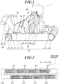
- FIG. 1 is a perspective view showing the entire configuration of the inkjet recording device 1 in the first embodiment.
- This inkjet recording device 1 includes a conveyance unit 10, an image recording unit 20 (recording unit), a reading unit 30, a control unit 40, a medium detecting unit 50 (detecting unit), a peeling operation unit 60, and the like.
- the conveyance unit 10 has a drive roller 11, a conveyance belt 12, a following roller 13, a conveyance motor 14, an encoder 15, a pressing roller 16, an anti-vibration roller 19 (anti-vibration unit), and the like.
- the conveyance belt 12 is an endless member, and tensioned between the drive roller 11 and the following roller 13. In accordance with the rotation movement of the drive roller 11 by the drive of the conveyance motor 14, the conveyance belt 12 performs the rotary movement along the rotary path.
- the conveyance unit 10 By performing the relative movement in a predetermined conveyance direction with respect to the image recording unit 20 with the outer circumferential surface (one surface) of the conveyance belt 12 as the conveyance surface, the conveyance unit 10 performs the conveyance operation of moving the recording medium P placed on the conveyance surface in the conveyance direction at a predetermined conveyance speed.
- the conveyance belt 12 there is used a material which flexibly curves at the contacting surfaces contacting the drive roller 11 and the following roller 13 and surely supports the recording medium P.
- a conveyance belt 12 there is a belt made of resin such as rubber, for example.
- the following roller 13 rotates in accordance with the movement of the conveyance belt 12.
- This conveyance belt 12 is formed and processed so as to prevent the rising of the placed recording medium P.
- an adhesive to attach the recording medium P is applied onto the surface (conveyance surface) of the conveyance belt 12.
- the conveyance unit 10 conveys the recording medium P by making the recording medium P adhere to the conveyance surface upstream, in the conveyance direction, of the image recording position (recording operation range) at which the image recording operation is performed by the image recording unit 20.
- the conveyance unit 10 pulls the recording medium P away from the conveyance surface by causing the peeling roller 61 to pull the recording medium P with a predetermined strength or more in a direction (upward in the drawing) separating from the conveyance belt 12, and thereby peels the recording medium P.
- the device structure itself of the reading unit 30 is large (broad) in the conveyance direction compared to the reading range, there is a possibility that the recording medium P contacts the reading unit 30 when the recording medium P is peeled immediately after the passage through the reading range.
- the peeling position is determined to be located after the passage of range (reading operation range) in the conveyance direction of the entire range (space) for the reading operation including the arrangement range of the reading unit 30 and the optical path of the light incident on the reading unit 30 from the reading range in addition to the reading range.
- the reading operation range also includes the space where the illumination light passes before reaching the reading range.
- the adhesive may be applied by the user, manager or the like regularly or irregularly according to the adhesion state.
- a medium which is continuous in the conveyance direction is used as the recording medium P.
- the recording medium P is fabric.
- a plurality of images recorded at appropriate intervals on the recording medium P are dried (ink is fixed) with a post-processing device not shown in the drawings, and the recording medium P is rolled up or shaken down, and/or each of the images is cut.
- the conveyance motor 14 rotates the drive roller 11 at a rotation speed according to the control signal from the control unit 40.
- the conveyance motor 14 can also rotate the drive roller 11 in the opposite direction to the normal conveyance direction.
- the conveyance belt 12 conveys the recording medium P at a conveyance speed according to the rotation speed of the drive roller 11.
- the encoder 15 detects the conveyance speed of the recording medium P.
- the encoder 15 is a rotary encoder which detects the rotation speed of the conveyance motor 14, however, the encoder 15 is not limited to this.
- the pressing roller 16 removes the risings from the placement surface such as wrinkles by pressing, against the placement surface, the recording medium P supplied to the placement surface of the conveyance belt 12.
- the anti-vibration roller 19 is provided to contact the internal circumferential surface side of the conveyance belt 12 (surface on the opposite side to one surface) so as to be rotatable at a position downstream of the reading operation range where the reading operation by the reading unit 30 is performed in the conveyance direction.
- the anti-vibration roller 19 suppresses the vibration of the conveyance belt 12 which is generated according to the rotary operation, by supporting the conveyance belt 12 from inside while performing the rotation operation in accordance with the rotary movement of the conveyance belt 12.
- the anti-vibration roller 19 is provided in the conveyance direction between a front light receiving unit 52 and a rear light receiving unit 53, which is the peeling range where the recording medium P is normally peeled.
- the anti-vibration roller 19 may be provided further upstream.
- the image recording unit 20 performs the recording operation of recording the image by ejecting ink from the nozzles and making the ink land on (applied to) the upper surface (surface on the opposite side to the side contacting the conveyance surface) of the recording medium P.
- the image recording unit 20 has a plurality of head units 21. These head units 21 eject ink of respective different colors supplied from ink containers not shown in the drawings.
- the number of the provided head units 21 that is, the number of colors of the ejected ink
- the type of the ink color are not especially limited.
- each of the head units 21 is a line head which has the nozzles one dimensionally or two dimensionally arranged in a plane parallel to the conveyance surface and which has the range in the width direction of the arrangement range of the nozzles determined according to the recordable width of the recording medium P which can be conveyed by the conveyance belt 12.
- FIG. 2 is a view schematically showing the surface (nozzle surface) facing the conveyance surface of the head unit 21K.
- head units 21C, 21M and 21Y also have the same configuration, the explanation thereof is omitted.
- the head unit 21K is provided with a plurality of (16 in the embodiment) ejection heads 211 in which nozzle openings are arranged on the bottom surface at predetermined intervals (nozzle intervals), for example, intervals of approximately 70.6 ⁇ m so as to correspond to 360 dpi (dot per inch) in the embodiment.
- nozzle intervals predetermined intervals
- Two ejection heads 211 form a pair and the nozzle openings of the ejection heads 211 are alternately arranged in the width direction. Thereby, image recording can be performed with the recording resolution of a total of 720 dpi (the nozzle interval is approximately 35.3 ⁇ m).
- the inkjet recording device 1 records an image by one pass method by fixing each of the head units 21 during the image recording operation, and sequentially ejecting ink at predetermined intervals (conveyance direction intervals) at different positions in the conveyance direction according to the conveyance of the recording medium P.
- the conveyance direction interval that is, the recording resolution in the conveyance direction is determined by the ejection frequency from the nozzles, the conveyance speed and the like, but may be equal to or different from the above-mentioned 720 dpi.
- the reading unit 30 reads the surface of the recording medium P placed on the conveyance belt 12.
- the reading unit 30 includes an image capturing sensor 31 (in-line sensor), and is provided downstream of the image recording position by the image recording unit 20 in the conveyance direction by the conveyance belt 12.
- the reading unit 30 can read the image which was recorded on the recording medium P by the image recording unit 20.
- the image capturing sensor 31 of the reading unit 30 is not especially limited, the image capturing sensor 31 in the embodiment is a line sensor which can read at once over the recordable width of the recording medium P in the width direction orthogonal to the conveyance direction.
- the reading data by the reading unit 30 is used for tests of the image quality and the image recording position of the recorded image on the recording medium P by the control unit 40, operation tests (such as defective ejection test of nozzles) of the image recording unit 20 based on the reading result of the test image which was recorded on the recording medium P, or for detection of abnormality of the recording medium P.
- the abnormality test of the recording medium P can include the test of abnormality based on the abnormality of the conveyance surface.
- the control unit 40 integrally controls the operations of the components in the inkjet recording device 1.
- the medium detecting unit 50 detects the peeling state from the conveyance belt 12 of the recording medium P.
- the medium detecting unit 50 includes a first light emitting unit 51 (light emitting unit), a front light receiving unit 52 (upstream light receiving unit), a rear light receiving unit 53 (downstream light receiving unit), a second light emitting unit 56, an upstream abnormality detection light receiving unit 57, and the like.
- the first light emitting unit 51, and the front light receiving unit 52 and the rear light receiving unit 53 are respectively provided near both lateral surfaces of the conveyance belt 12 at an interval larger than the maximum width of the recording medium P which can be the conveyance target by the conveyance belt 12 in the width direction.
- the front light receiving unit 52 is provided at a position located upstream of the first light emitting unit 51 (emitting position of emitted light) and downstream of the above-mentioned reading operation range by the reading unit 30 in the conveyance direction.
- the rear light receiving unit 53 is provided at a position downstream, in the conveyance direction, of the first light emitting unit 51 (emitting position of emitted light).
- the first light emitting unit 51 emits two rays of light (or light radiating out in a predetermined angle range) with a directivity to cross above the conveyance belt 12 with an inclination of a predetermined angle (that is, oblique direction) with respect to each of the conveyance direction and the width direction.
- the peeling state of the recording medium P on the path of emitted light is detected by whether or not the emitted light (emitted light) is detected by each of the front light receiving unit 52 and the rear light receiving unit 53.
- the second light emitting unit 56 and the upstream abnormality detection light receiving unit 57 are arranged upstream, in the conveyance direction, of the first light emitting unit 51, the front light receiving unit 52 and the rear light receiving unit 53 and between the first light emitting unit 51, the front light receiving unit 52 and the rear light receiving unit 53 and the reading unit 30 (image capturing sensor 31).
- the second light emitting unit 56 and the upstream abnormality detection light receiving unit 57 form a first peeling abnormality detecting unit which detects the state of peeling abnormality (here, the state in which the peeling is performed too early) when the peeling position of the recording medium P moves to an abnormal peeling position upstream of the normal peeling range (reference peeling range NA shown in FIG. 4A ).
- the first light emitting unit 51 and the second light emitting unit 56 emit light of appropriate wavelengths
- the front light receiving unit 52, the rear light receiving unit 53 and the upstream abnormality detection light receiving unit 57 detect light of at least a part of the wavelengths of the light which was emitted by the first light emitting unit 51 and the second light emitting unit 56.
- the peeling operation unit 60 pulls (peels) the recording medium P away from the conveyance belt 12 at an appropriate position, the recording medium P adhering to the conveyance surface of the conveyance belt 12 of the conveyance unit 10 and being conveyed, and the peeling operation unit 60 sends the recording medium P to the post-processing device not shown in the drawings.
- the peeling operation unit 60 includes the peeling roller 61, the peeling motor 62, and the like.
- the peeling roller 61 pulls the recording medium P away from the conveyance surface to send it to the post-processing device by pulling upward the recording medium P, which has been conveyed in a state of adhering to the conveyance belt 12, from the outer circumferential surface of the conveyance belt 12 with a predetermined pressure according to the rotation operation by the peeling motor 62. It is preferable that the surface of the peeling roller 61 has a large friction against the recording medium P, which can apply an effective peeling force to the recording medium P.
- the peeling roller 61 contacts only the surface on the opposite side to the image recording surface so that the image does not deteriorate due to the contact of the roller or the like with the ink landing surface (image recording surface) of the recording medium P until the ink which landed on the recording medium P is fixed and dried by the post-processing device.
- the peeling motor 62 rotates the peeling roller 61 at a rotation speed according to the control signal from the control unit 40. Normally, the peeling motor 62 rotates the peeling roller 61 to pull up the recording medium P at a speed which is synchronized with the conveyance speed of the recording medium P.
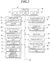
- FIG. 3 is a block diagram showing the functional configuration of the inkjet recording device 1 in the embodiment.
- the inkjet recording device 1 includes a control unit 40, a storage unit 45, a conveyance motor 14 and an encoder 15 of the conveyance unit 10, a head driving unit 22 of the image recording unit 20, the image capturing sensor 31 of the reading unit 30, the first light emitting unit 51, the front light receiving unit 52, the rear light receiving unit 53, the second light emitting unit 56 and the upstream abnormality detection light emitting unit 57 of the medium detecting unit 50, the peeling motor 62 of the peeling operation unit 60, the communication unit 70, the operation display unit 80, the bus 90, and the like.
- the control unit 40 performs the control operation of integrally controlling the entire operation of the inkjet recording device 1.
- the control unit 40 includes a CPU 41 (Central Processing Unit), a ROM 42 (Read Only Memory), a RAM 43 (Random Access Memory), and the like.
- the CPU 41 performs various types of arithmetic processing and executes the processing for various types of controls.
- the control programs for the various types of controls are stored and saved in the ROM 42.
- As the ROM 42 a mask ROM or a readable and writable nonvolatile memory is used.
- the RAM 43 provides a working memory space to the CPU 41, and stores temporary data and various types of settings.
- various types of volatile memories such as a SRAM and a DRAM are used.
- the storage unit 45 stores recording target image data (recording target data) obtained via the communication unit 70, its processing data, and the like.
- the storage unit 45 may store other various types of execution programs for image recording and adjustment test.
- the CPU 41 executes the execution programs, the CPU 41 uses the programs by reading out the programs and loads them in the RAM 43.
- As the storage unit 45 for example, an HDD (Hard Disk Drive) or a flash memory is used.
- a RAM or the like may be used together.
- the conveyance motor 14 causes the conveyance belt 12 to perform the rotary movement by rotating the drive roller 11 in accordance with the control signal from the control unit 40.
- the rotation speed of the conveyance motor 14 may be changeable according to the image quality or the like required in the recorded image.
- the head driving unit 22 outputs a drive signal for operating the ink ejection mechanism in the ejection head 211 of each of the head units 21, and causes ink to be ejected from the nozzle opening of the operation target at an appropriate timing.
- These drive signals are output to each of the head units 21 (ejection heads 211) in a parallel manner.
- the drive signal is output in synchronization with the encoder (not shown in the drawings) which measures the conveyance speed (position) of the recording medium P by the conveyance unit 10.
- the ink ejection mechanism for example, a piezo type, a thermal type and the like are used.
- the piezo type deforms the piezoelectric elements by applying a voltage to the piezoelectric elements provided along the ink flow path communicated with the nozzles and applies a pressure with a predetermined pressure pattern to the ink in the ink flow path, to cause the ink to be ejected.
- the thermal type generates heat by making electric current through the electrically heating wire, generates the change in volume by heating the ink in the ink flow path and vaporizing part of ink, and applies a pressure to the ink to eject the ink.
- the image capturing sensor 31 is a line sensor as mentioned above, and outputs a one-dimensional image by capturing the image of the upper surface of the recording medium P (recording surface by the image recording unit 20).
- the image capturing sensor 31 can output a two-dimensional image of the upper surface of the recording medium P by capturing the one-dimensional image and outputting the image at predetermined intervals according to the conveyance speed of the recording medium P by the conveyance unit 10.
- the first light emitting unit 51 and the second light emitting unit 56 emit predetermined light when the recording medium P is conveyed.
- This light is preferably a light having a strong directivity, and for example, a laser light, though not especially limited.
- the wavelength of light is also not especially limited, it is preferable not to be greatly influenced by external light.
- the infrared light or the like is used, for example. Visible light, for example, red color light may be emitted together with the infrared light so as to indicate to the user or the manager that the light emitting operation of the first light emitting unit 51 and the second light emitting unit 56 is performed appropriately.
- the front light receiving unit 52, the rear light receiving unit 53 and the upstream abnormality detection light receiving unit 57 detect incident light, and output a signal (electric charge amount, voltage value, electric current value or the like) according to the incident light amount.
- Each of the light receiving surfaces of the front light receiving unit 52, the rear light receiving unit 53 and the upstream abnormality detection light receiving unit 57 is provided to be nearly perpendicular to the optical axis (or width direction) of the emitted light from the first light emitting unit 51 and the second light emitting unit 56, and detects at least a part of the wavelengths of the emitted light.
- the front light receiving unit 52, the rear light receiving unit 53 and the upstream abnormality detection light receiving unit 57 detect only the infrared light, and thereby it is possible to reduce the influence by the external light.
- the front light receiving unit 52 and the rear light receiving unit 53 may make the signal corresponding to the incident light amount binary with a predetermined reference value, and output only the information regarding presence/absence of the light emission from the first light emitting unit 51 and the second light emitting unit 56.
- the peeling motor 62 rotates and moves the peeling roller 61. According to the control signal from the control unit 40, the peeling motor 62 pulls the recording medium P, which moves in accordance with the rotary movement of the conveyance belt 12, away from the conveyance belt 12, and adjusts the peeling position of the recording medium P by changing the rotation speed.
- the communication unit 70 obtains the recording target image data and the print job from the external computer terminal, the print server, and the like, and outputs a status signal regarding the image recording.
- the operation display unit 80 has a display unit 81 which displays an input operation receiving screen for a user and status information, and an operation receiving unit 82 which receives user's input operation and outputs the operation signal to the control unit 40.
- the operation display unit 80 has a liquid crystal screen provided with a touch sensor and its driver, for example.
- the display unit 81 there may be used a display screen of other display methods such as an organic EL display, or an LED lamp for displaying status or the like may be used together.
- the operation receiving unit 82 push button switches, a rotation switch or the like may be used instead of or in addition to the touch panel.
- the bus 90 is a transmission path for transmission and reception of signals between the control unit 40 and the other components.
- the recording medium P adhering to the conveyance belt 12 is peeled. Since the peeling position by the peeling roller 61 in this case is determined by the relationship of strength between the pulling force for the peeling and the adhesion force, the peeling position is not necessarily fixed at a constant position. Accordingly, in the inkjet recording device 1, the medium detecting unit 50 detects whether or not the peeling is performed in a positional range not providing a bad influence on the reading operation, especially, downstream of the reading operation range by the reading unit 30.
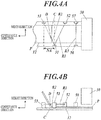
- FIGS. 4A, 4B , 5A, 5B and 5C are views for explaining the detection of the peeling state.
- FIGS. 4A and 4B are views for explaining the detection state of the recording medium P in a case where the peeling is performed normally.
- FIG. 4A is a plan view seen from the side (upper side) facing the image recording surface of the recording medium P.
- FIG. 4B is a front view seen from the width direction.
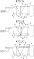
- FIGS. 5A to 5C are front views for explaining the detection state of the recording medium P in a case where the peeling position is out of the normal range.
- the path of the emitted light R2 from the first light emitting unit 51 to the rear light receiving unit 53 is determined to cross the reference peeling range NA (predetermined peeling range) which is the normal peeling range of the recording medium P.
- the reference peeling range NA predetermined peeling range
- the emitted light R2 from the first light emitting unit 51 to the rear light receiving unit 53 is interrupted at the position D on the recording medium P which was peeled from the conveyance belt 12 and rose. Accordingly, the rear light receiving unit 53 does not detect the emitted light R2 from the first light emitting unit 51.
- the emitted light R1 from the first light emitting unit 51 is detected by the front light receiving unit 52.
- the recording medium P does not interfere with the emitted light R2 from the first light emitting unit 51 to the rear light receiving unit 53.
- the detection state changes into a state in which the emitted lights R1 and R2 are respectively detected by the front light receiving unit 52 and the rear light receiving unit 53.
- the recording medium P rising from the conveyance surface interferes with the emitted light R1 from the first light emitting unit 51 to the front light receiving unit 52 at the position D on the recording medium P. Accordingly, the front light receiving unit 52 does not detect the emitted light R1 from the first light emitting unit 51.
- the emitted light R2 from the first light emitting unit 51 is detected by the rear light receiving unit 53.
- the tension applied to the recording medium P is raised by temporarily raising the rotation speed of the peeling roller 61 by the peeling motor 62, and the peeling position CB is moved upstream.
- the control operation of appropriately returning the rotation speed of the peeling roller 61 is performed.
- the abnormality is detected by the interference of the emitted light R3 from the second light emitting unit 56 to the upstream abnormality detection light receiving unit 57 at the position D.
- the conveyance operation by the conveyance unit 10 and the image recording operation by the image recoding unit 20 are promptly stopped.
- FIG. 6 is a flowchart showing a control procedure by the control unit 40 of the peeling control processing executed by the inkjet recording device 1 in the embodiment.
- This peeling control processing is invoked and started in accordance with start of the conveyance operation (rotation operation of the conveyance motor 14) of the conveyance unit 10, and continued while the conveyance operation (rotation operation) is continued.
- control unit 40 (CPU 41) causes the first light emitting unit 51 and the second light emitting unit 56 to start the light emitting operation (step S101).
- the control unit 40 obtains detection information of the incident light from each of the front light receiving unit 52, the rear light receiving unit 53, and the upstream abnormality detection light receiving unit 57 (step S102).
- the control unit 40 determines whether or not the upstream abnormality detection light receiving unit 57 did not detect the light amount which is a reference or more (step S103). If the control unit 40 determines that the upstream abnormality detection light receiving unit 57 did not detect the light amount (step S103; YES), the control unit 40 determines that the peeling abnormality was detected and causes the display 81 to perform a predetermined notification operation indicating the peeling abnormality, and stops the conveyance operation by the conveyance unit 10, the peeling operation by the peeling operation unit 60 and the image recording operation by the image recording unit 20 (step S113). Then, the control unit 40 ends the peeling control processing.
- step S103 determines whether or not the light amount which is the reference or more was detected by the front light receiving unit 52 and was not detected by the rear light receiving unit 53 (step S104). If the control unit 40 determines that the light amount which is the reference or more was detected by the front light receiving unit 52 and was not detected by the rear light receiving unit 53 (step S104; YES), the control unit 40 rotates the peeling motor 62 at a normal speed (step S114). If the peeling motor 62 is already rotating at the normal speed, the control unit 40 may continue the control operation without change. The processing of the control unit 40 then returns to step S102.
- step S104 determines whether or not the light amount which is the reference or more was not detected by the front light receiving unit 52 or was detected by the rear light receiving unit 53 (step S105). If the control unit 40 determines that the light amount which is the reference or more was not detected by the front light receiving unit 52 and was detected by the rear light receiving unit 53 (step S105; YES), the control unit 40 rotates the peeling motor 62 at a predetermined low speed which is lower than the normal speed (step S115). If the peeling motor 62 is already rotating at the low speed, the control unit 40 may continue the control operation without change. The processing of the control unit 40 then returns to step S102.
- step S105 determines whether or not the light amount which is the reference or more was detected by the front light receiving unit 52 and was detected by the rear light receiving unit 53 (step S106). If the control unit 40 determines that the light amount which is the reference or more was detected by the front light receiving unit 52 and was detected by the rear light receiving unit 53 (step S106; YES), the control unit 40 rotates the peeling motor 62 at a predetermined high speed which is higher than the normal speed (step S116). If the peeling motor 62 is already rotating at the high speed, the control unit 40 may continue the control operation without change. The processing of the control unit 40 then returns to step S102.
- control unit 40 determines that the light amount which is the reference or more was not detected by the front light receiving unit 52 or was not detected by rear light receiving unit 53 (that is, if the light amount which is the reference or more was not detected from either light receiving unit) (step S106; NO), the detection abnormality is occurring.
- the control unit 40 causes the display unit 81 to perform the predetermined notification operation indicating the detection abnormality, and stops all the operations for the image recording (step S107). The control unit 40 then ends the peeling control processing.
- an inkjet recording device 1 in the embodiment includes: a conveyance unit 10 which conveys a recording medium P by making the recording medium P adhere to the conveyance surface; an image recording unit 20 which records an image on the recording medium P adhering to the conveyance surface; a reading unit 30 which reads the surface of the recording medium P in the downstream of the recording operation range in a conveyance direction of the recording medium P by the conveyance unit 10, the recording operation range being a recording operation range of the image by the image recording unit 20 in the conveyance path of the recording medium P by the conveyance unit 10; a peeling operation unit 60 which peels the recording medium P adhering to the conveyance surface by pulling the recording medium P away from the conveyance surface; and a medium detecting unit 50 which detects the peeling state from the conveyance surface of the recording medium P in the downstream, in the conveyance direction, of the reading operation range by the reading unit 30.
- the inkjet recording device 1 having the conveyance unit 10 which makes the recording medium P adhere to the conveyance surface, it is not necessary to determine a large peeling possible range in the downstream of the reading unit 30 in consideration of variance of the peeling position, and it is possible to read the image with the reading unit 30 and thereafter peel the recording medium P appropriately without increasing the size. Accordingly, it is possible to exclude the defective image, perform the maintenance of the inkjet head, and the like appropriately. It is possible to prevent the peeling position of the recording medium P from providing the bad influence on the reading operation, by appropriately detecting the peeling state of the recording medium P in the downstream of the reading operation range by the medium detecting unit 50.
- the medium detecting unit 50 has a first light emitting unit 51, and a front light receiving unit 52 and a rear light receiving unit 53 which detect the emitted light from the first light emitting unit 51, and the medium detecting unit 50 detects the peeling state by the change in the incidence state of the emitted light from the first light emitting unit 51 to the front light receiving unit 52 and the rear light receiving unit 53 according to the presence/absence of the rising of the recording medium P from the conveyance surface, the rising following the peeling of the recording medium P.
- the peeling position can be maintained not to largely get out of the reading operation range so that the reading operation of the recording medium can be performed easily and surely, by detecting the presence/absence of the peeling of the recording medium with a transmission type optical sensor.
- the path of the emitted light from the first light emitting unit 51 is determined in an oblique direction with respect to each of the conveyance direction and the width direction (in the embodiment, further determined to be within a plane parallel to the conveyance surface).
- the peeling position along the conveyance direction can be detected not at one point but in a predetermined width.
- the detection errors and detection leak do not easily occur, and it is possible to classify whether or not the peeling position is located in the appropriate range more easily and surely.
- the medium detecting unit 50 has two light receiving units which are the front light receiving unit 52 and the rear light receiving unit 53, and the two light receiving units are arranged so as to be able to determine which of inside, upstream and downstream of the reference peeling range NA in the conveyance direction the peeling position of the recording medium P is located, according to the combination of the detection results of the emitted light from the first light emitting unit 51 by the two light receiving units.
- the reading operation is easy to perform more stably by easy control.
- the first light emitting unit 51 emits the emitted light to each of the two light receiving units which are the front light receiving unit 52 that detects the emitted light upstream of the emitting position of the emitted light in the conveyance direction, and the rear light receiving unit 53 that detects the emitted light downstream of the emitting position in the conveyance direction.
- the front light receiving unit 52 that detects the emitted light upstream of the emitting position of the emitted light in the conveyance direction
- the rear light receiving unit 53 that detects the emitted light downstream of the emitting position in the conveyance direction.
- the inkjet recording device 1 further includes a control unit 40 which controls the operation of the peeling operation unit 60 so that the peeling position is located in the reference peeling range NA on the basis of the detection result of the medium detecting unit 50.
- a control unit 40 which controls the operation of the peeling operation unit 60 so that the peeling position is located in the reference peeling range NA on the basis of the detection result of the medium detecting unit 50.
- the peeling operation unit 60 pulls up the recording medium P in a direction separating from the conveyance surface at a speed which is synchronized with the conveyance speed of the recording medium P by the conveyance unit 10, and the control unit 40 changes the speed of the pulling up on the basis of the positional relationship between the peeling position and the reference peeling range NA.
- the peeling operation unit 60 can maintain the peeling position without largely shifting the peeling position easily and generally stably, and the minor correction can be gradually performed to the peeling position even if the peeling position is shifted a little. Thus, it is possible to continue the image recording operation in a continuous manner without providing the bad influence on the image recording operation and the reading operation.
- the inkjet recording device 1 further includes a second light emitting unit 56 and an upstream abnormality detection light receiving unit 57 which detect the peeling abnormality of the recording medium P on a side that is upstream of the reference peeling range NA and downstream of the reading operation range in the conveyance direction.
- a second light emitting unit 56 and an upstream abnormality detection light receiving unit 57 which detect the peeling abnormality of the recording medium P on a side that is upstream of the reference peeling range NA and downstream of the reading operation range in the conveyance direction.
- the conveyance surface of the recording medium P is one surface (outer circumferential surface) of the conveyance belt 12 which is an endless member that performs a rotary movement along a predetermined rotary path, and an anti-vibration roller 19 which suppresses vibration of the conveyance belt 12 is provided between the position located most downstream in the reading operation range and the position located most downstream in the reference peeling range NA in the conveyance direction.
- the inkjet recording device 1 it is possible to prevent or reduce the bad influence on the reading operation by the reading unit 30 and the image recording operation by the image recording unit 20 by reducing the transmission along the conveyance belt 12 of the minute vibration which easily occurs according to the peeling operation of the recording medium P that is performed resisting the adhesive force.
- the anti-vibration roller 19 is provided to contact the surface on the opposite side to the outer circumferential surface (conveyance surface) of the conveyance belt 12, and rotates in accordance with the rotary movement of the conveyance belt 12. Accordingly, in the inkjet recording device 1, it is possible to reduce the vibration of the conveyance belt 12 effectively without interfering the rotary operation of the conveyance belt 12 with an easy configuration.
- FIG. 7 is a perspective view showing the entire configuration of an inkjet recording device 1a in the embodiment.
- the inkjet recording device 1a includes two independent light emitting units 511 and 512 respectively corresponding to the front light receiving unit 52 and the rear light receiving unit 53 in the medium detecting unit 50.
- a third light emitting unit 58 and a downstream abnormality detection light receiving unit 59 are provided in the further downstream, in the conveyance direction, of the rear light receiving unit 53.
- the anti-vibration roller 19 supports the inner surface side of the conveyance belt 12 on the opposite side to the reading range by the reading unit 30.
- one light emitting unit and one light receiving unit form a pair, and are provided at positions which are equal to each other in the conveyance direction.
- the recording medium P interferes with the incidence of the emitted light to the light receiving unit from the light emitting unit only at the timing when the peeling position moves forward or backward and crosses between the light emitting unit and the light receiving unit.
- the third light emitting unit 58 and the downstream abnormality detection light receiving unit 59 are arranged downstream, in the conveyance direction, of the first light emitting unit 51, the front light receiving unit 52 and the rear light receiving unit 53, and form a second peeling abnormality detecting unit which detects the state of peeling abnormality (in the embodiment, the state in which the peeling is performed too late) in a case where the peeling position of the recording medium P moves to an abnormal peeling position located downstream of the normal peeling range (reference peeling range NA).
- FIG. 8 is a flowchart showing a control procedure by the control unit 40 of the peeling control processing executed in the inkjet recording device 1a in the embodiment.
- control unit 40 starts the light emitting operations of the light emitting units 511 and 512, the second light emitting unit 56, and the third light emitting unit 58 (step S121).
- the control unit 40 obtains light detection information from the front light receiving unit 52, the rear light receiving unit 53, the upstream abnormality detection light receiving unit 57, and the downstream abnormality detection light receiving unit 59 (step S122).
- the control unit 40 determines whether or not the reduction in light amount of a reference or more was detected in the upstream abnormality detection light receiving unit 57 or the downstream abnormality detection light receiving unit 59 (step S123). If it is determined that the reduction was detected (step S123; YES), the control unit 40 causes the display unit 81 to notify that the peeling abnormality was detected, and stops the conveyance operation of the conveyance unit 10, the peeling operation of the peeling operation unit 60, and the image recording operation by the image recording unit 20 (step S133). The control unit 40 then ends the peeling control processing.
- step S123 the control unit 40 determines whether or not the front light receiving unit 52 detected the reduction in light amount of the reference or more (step S124). If it is determined the reduction was detected (step S124; YES), the control unit 40 determines whether or not the peeling motor 62 is currently operating at the low speed (step S134). If it is determined that the peeling motor 62 is not operating at the low speed (step S134; NO), the control unit 40 changes the operation of the peeling motor 62 to the above-mentioned low speed operation (step S144). The processing of the control unit 40 then returns to step S102.
- step S134 If it is determined that the peeling motor 62 is operating at the low speed (step S134; YES), the control unit 40 changes the operation of the peeling motor 62 to the normal speed operation (step S136). The processing of the control unit 40 then returns to step S102.
- step S124 if it is determined that the reduction in light amount of the reference or more was not detected by the front light receiving unit 52 (step S124; NO), the control unit 40 determines whether or not the reduction in light amount of the reference or more was detected by the rear light receiving unit 53 (step S125). If it is determined that the reduction in light amount was detected (step S125; YES), the control unit 40 determines whether or not the peeling motor 62 is currently operating at the high speed (step S135). If it is determined that the peeling motor 62 was not operating at the high speed (step S135; NO), the control unit 40 changes the operation of the peeling motor 62 to the high speed operation (step S145). The processing of the control unit 40 then returns to step S102.
- step S135 If it is determined that the peeling motor 62 is operating at the high speed (step S135; YES), the processing of the control unit 40 proceeds to step S136, and the control unit 40 changes the operation of the peeling motor 62 to the normal speed operation (step S136).
- step S125 if it is determined that the reduction in light amount of the reference or more was not detected by the rear light receiving unit 53 (step S125; NO), the processing of the control unit 40 returns to step S102.
- the inkjet recording device 1a in the second embodiment includes the third light emitting unit 58 and the downstream abnormality detection light receiving unit 59 which detect the peeling abnormality of the recording medium P downstream of the reference peeling rage NA in the conveyance direction.
- the third light emitting unit 58 and the downstream abnormality detection light receiving unit 59 which detect the peeling abnormality of the recording medium P downstream of the reference peeling rage NA in the conveyance direction.
- the present invention is not limited to the above embodiments, and various changes can be made.
- the first embodiment has been described for a case of having a configuration for detecting the abnormality upstream of the reference peeling range NA in the conveyance direction in addition to the normal peeling detection
- the second embodiment has been described for a case of having a configuration for detecting the abnormality downstream in addition to the upstream.
- the configuration for detecting the abnormality may be provided only downstream, or may not be provided on either side.
- the emitted light is emitted to the front light receiving unit 52 and the rear light receiving unit 53 from the same emitting position of the first light emitting unit 51.
- the emitting position to the front light receiving unit 52 may be located downstream of the emitting position to the rear light receiving unit 53.
- the appropriate peeling position can be determined to be in such a range that the emitted light is not detected in the front light receiving unit 52 or the rear light receiving unit 53.
- the detection result is classified into four patterns which are a case of not detecting emitted light in the front light receiving unit 52 or the rear light receiving unit 53, cases of detecting emitted light in only one of them, and a case of detecting emitted light in both of them.
- the range of detecting the emitted light in both of them may be determined to be the range of abnormal peeling state so as not to provide another configuration for detecting the abnormality.
- both of the emitted light from the light emitting unit 511 to the front light receiving unit 52 and the emitted light from the light emitting unit 512 to the rear light receiving unit 53 are in the direction perpendicular to the conveyance direction.
- at least one of them may be in an oblique direction to the conveyance direction in the range of not overlapping the conveyance direction.
- both of the emitted lights are in the oblique directions to the conveyance direction, they may be parallel or not parallel to each other.
- the reference peeling range NA is determined between the light emitting position of the first light emitting unit 51 and the light receiving position of the rear light receiving unit 53 in the conveyance direction.
- the reference peeling range NA may be between the light emitting position of the first light emitting unit 51 and the light receiving position of the front light receiving unit 52.
- Which to select from among the setting of the embodiments and this setting may be determined according to a distance which is necessary between the reference peeling range NA and the reading operation range, for example, the attenuation degree or the like until transmission to the reading operation range of the vibration of the conveyance belt 12 which is generated when the recording medium P is peeled at the peeling position.
- the inclination angle to the conveyance direction of the emitted light to the front light receiving unit 52 may be different from the inclination angle to the conveyance direction of the emitted light to the rear light receiving unit 53.
- the present invention is not limited to this.
- the configuration may be able to detect the peeling position only at the upstream-side end of the reference peeling range NA, or detect only whether or not the peeling position is located inside the reference peeling range NA.
- a plurality of detecting units may be provided so as to be able to quantitatively evaluate the peeling position so that the control unit 40 controls the operation of the peeling motor 62 in a more detailed manner.
- the peeling motor 62 is described as a motor which rotates at three steps of speed in the above embodiments, the speed may be changed continuously or step by step at the time of switching the speed.
- control unit 40 directly performs control according to the presence/absence of detection of the emitted light by the front light receiving unit 52 and the rear light receiving unit 53 in the above embodiments, a signal may be output to the peeling motor 62 via the PLC (Programmable Logic Controller) or the like.
- PLC Programmable Logic Controller
- the anti-vibration roller 19 is provided in the above embodiments, the anti-vibration roller 19 may not be provided.
- the conveyance belt 12 may be supported by a plate-like member such as platen instead of the anti-vibration roller 19, or a plurality of rollers may be arranged at appropriate intervals.
- the image recording device of the present invention also includes a device which performs processing of coating, applying gloss, and the like with a colorless ink.
- the present invention can also be applied to other image recording devices, such as a case of providing an image capturing sensor used for test of LED elements in an LED printer, for example.
- the present invention can be used for an image recording device.
Landscapes
- Engineering & Computer Science (AREA)
- Textile Engineering (AREA)
- Ink Jet (AREA)
- Handling Of Sheets (AREA)
- Controlling Sheets Or Webs (AREA)
- Separation, Sorting, Adjustment, Or Bending Of Sheets To Be Conveyed (AREA)
Applications Claiming Priority (2)
| Application Number | Priority Date | Filing Date | Title |
|---|---|---|---|
| JP2016244441 | 2016-12-16 | ||
| PCT/JP2017/044842 WO2018110630A1 (ja) | 2016-12-16 | 2017-12-14 | 画像記録装置 |
Publications (3)
| Publication Number | Publication Date |
|---|---|
| EP3556696A1 true EP3556696A1 (de) | 2019-10-23 |
| EP3556696A4 EP3556696A4 (de) | 2019-12-25 |
| EP3556696B1 EP3556696B1 (de) | 2022-02-16 |
Family
ID=62558929
Family Applications (1)
| Application Number | Title | Priority Date | Filing Date |
|---|---|---|---|
| EP17882048.6A Active EP3556696B1 (de) | 2016-12-16 | 2017-12-14 | Bildaufzeichnungsvorrichtung |
Country Status (3)
| Country | Link |
|---|---|
| EP (1) | EP3556696B1 (de) |
| JP (1) | JP7070430B2 (de) |
| WO (1) | WO2018110630A1 (de) |
Families Citing this family (3)
| Publication number | Priority date | Publication date | Assignee | Title |
|---|---|---|---|---|
| US11732409B2 (en) * | 2020-10-01 | 2023-08-22 | Xerox Corporation | Textiles custom printed with antimicrobial nanoparticles |
| EP4613495A1 (de) * | 2023-03-29 | 2025-09-10 | Kyocera Corporation | Druckvorrichtung, drucksystem und druckverfahren |
| CN120759086B (zh) * | 2025-09-08 | 2025-12-05 | 江苏千瑞纺织科技有限公司 | 一种提花纺织面料生产用宽幅检测装置 |
Family Cites Families (7)
| Publication number | Priority date | Publication date | Assignee | Title |
|---|---|---|---|---|
| JPH0753120A (ja) * | 1993-08-06 | 1995-02-28 | Canon Aptecs Kk | 紙搬送装置 |
| JP2002372500A (ja) * | 2001-06-14 | 2002-12-26 | Canon Inc | 欠陥検出装置および欠陥検出方法 |
| JP4617999B2 (ja) * | 2005-05-18 | 2011-01-26 | コニカミノルタホールディングス株式会社 | プリンタ |
| JP5410875B2 (ja) * | 2009-07-30 | 2014-02-05 | セーレン株式会社 | インクジェット記録装置およびインクジェット記録方法 |
| WO2013161622A1 (ja) | 2012-04-24 | 2013-10-31 | セーレン株式会社 | インクジェット記録装置 |
| JP6213723B2 (ja) * | 2013-09-17 | 2017-10-18 | セイコーエプソン株式会社 | 記録装置及び記録方法 |
| US9227434B2 (en) * | 2014-05-19 | 2016-01-05 | Eastman Kodak Company | Precision registration in a digital printing system |
-
2017
- 2017-12-14 JP JP2018556734A patent/JP7070430B2/ja active Active
- 2017-12-14 WO PCT/JP2017/044842 patent/WO2018110630A1/ja not_active Ceased
- 2017-12-14 EP EP17882048.6A patent/EP3556696B1/de active Active
Also Published As
| Publication number | Publication date |
|---|---|
| JPWO2018110630A1 (ja) | 2019-11-07 |
| WO2018110630A1 (ja) | 2018-06-21 |
| EP3556696A4 (de) | 2019-12-25 |
| JP7070430B2 (ja) | 2022-05-18 |
| EP3556696B1 (de) | 2022-02-16 |
Similar Documents
| Publication | Publication Date | Title |
|---|---|---|
| JP4895978B2 (ja) | 画像形成ドラムにインクを射出するインクジェットを正規化する方法およびインクジェット画像形成装置 | |
| US20120194588A1 (en) | Printing apparatus and printing method | |
| JP6335591B2 (ja) | 画像処理方法及び画像処理装置 | |
| US10086616B2 (en) | Image forming apparatus and quality determination method | |
| EP3556696B1 (de) | Bildaufzeichnungsvorrichtung | |
| US20180170699A1 (en) | Inkjet recording apparatus | |
| JP2011177944A (ja) | プリント装置 | |
| JP5899222B2 (ja) | インクジェット印刷方法およびインクジェットプリンタ | |
| US6412902B2 (en) | Printing head inspecting device and method for printer | |
| WO2017217173A1 (ja) | 情報処理装置、インクジェット記録装置及び情報処理方法 | |
| JP6082170B2 (ja) | 画像読取装置及び印刷装置 | |
| JP2005199606A (ja) | 画像形成装置及び記録ヘッド制御方法 | |
| JP2019104214A (ja) | 液体吐出装置、液体吐出システム、及び液体吐出装置のリフレッシュ方法 | |
| JP7062991B2 (ja) | 検出装置、インクジェット記録装置及び検出方法 | |
| US8172351B2 (en) | Printing apparatus and printing method | |
| CN108883633B (zh) | 喷墨记录装置以及喷墨记录装置的记录控制方法 | |
| JP2011131425A (ja) | 印刷装置におけるドット抜け検査方法、および印刷装置 | |
| JP7463762B2 (ja) | 画像記録装置、異常検出制御方法及びプログラム | |
| JP2011020305A (ja) | 画像形成装置及びプログラム | |
| US20050276649A1 (en) | Method of printing on thermal media | |
| JP7468129B2 (ja) | テスト画像データ生成装置、インクジェット記録装置及びテスト画像データ生成方法 | |
| KR100601691B1 (ko) | 열반응 용지의 화상정렬 인쇄방법 | |
| JP6050838B2 (ja) | ドット検出方法およびカラー画像再生装置 | |
| JP2014014978A (ja) | 吐出調整パターン形成方法、インクジェットヘッドの吐出調整方法、及び、インクジェットプリンタ | |
| WO2018016159A1 (ja) | インクジェット記録装置及びインクジェット記録装置の制御方法 |
Legal Events
| Date | Code | Title | Description |
|---|---|---|---|
| STAA | Information on the status of an ep patent application or granted ep patent |
Free format text: STATUS: THE INTERNATIONAL PUBLICATION HAS BEEN MADE |
|
| PUAI | Public reference made under article 153(3) epc to a published international application that has entered the european phase |
Free format text: ORIGINAL CODE: 0009012 |
|
| STAA | Information on the status of an ep patent application or granted ep patent |
Free format text: STATUS: REQUEST FOR EXAMINATION WAS MADE |
|
| 17P | Request for examination filed |
Effective date: 20190605 |
|
| AK | Designated contracting states |
Kind code of ref document: A1 Designated state(s): AL AT BE BG CH CY CZ DE DK EE ES FI FR GB GR HR HU IE IS IT LI LT LU LV MC MK MT NL NO PL PT RO RS SE SI SK SM TR |
|
| AX | Request for extension of the european patent |
Extension state: BA ME |
|
| A4 | Supplementary search report drawn up and despatched |
Effective date: 20191122 |
|
| RIC1 | Information provided on ipc code assigned before grant |
Ipc: B41J 2/01 20060101ALI20191118BHEP Ipc: B41J 15/04 20060101ALI20191118BHEP Ipc: D06B 11/00 20060101ALI20191118BHEP Ipc: B65H 43/08 20060101AFI20191118BHEP Ipc: B41J 11/42 20060101ALI20191118BHEP Ipc: B41J 3/407 20060101ALI20191118BHEP Ipc: B65H 41/00 20060101ALI20191118BHEP |
|
| DAV | Request for validation of the european patent (deleted) | ||
| DAX | Request for extension of the european patent (deleted) | ||
| GRAP | Despatch of communication of intention to grant a patent |
Free format text: ORIGINAL CODE: EPIDOSNIGR1 |
|
| STAA | Information on the status of an ep patent application or granted ep patent |
Free format text: STATUS: GRANT OF PATENT IS INTENDED |
|
| INTG | Intention to grant announced |
Effective date: 20211122 |
|
| GRAS | Grant fee paid |
Free format text: ORIGINAL CODE: EPIDOSNIGR3 |
|
| GRAA | (expected) grant |
Free format text: ORIGINAL CODE: 0009210 |
|
| STAA | Information on the status of an ep patent application or granted ep patent |
Free format text: STATUS: THE PATENT HAS BEEN GRANTED |
|
| AK | Designated contracting states |
Kind code of ref document: B1 Designated state(s): AL AT BE BG CH CY CZ DE DK EE ES FI FR GB GR HR HU IE IS IT LI LT LU LV MC MK MT NL NO PL PT RO RS SE SI SK SM TR |
|
| REG | Reference to a national code |
Ref country code: GB Ref legal event code: FG4D |
|
| REG | Reference to a national code |
Ref country code: CH Ref legal event code: EP |
|
| REG | Reference to a national code |
Ref country code: DE Ref legal event code: R096 Ref document number: 602017053564 Country of ref document: DE |
|
| REG | Reference to a national code |
Ref country code: AT Ref legal event code: REF Ref document number: 1468761 Country of ref document: AT Kind code of ref document: T Effective date: 20220315 |
|
| REG | Reference to a national code |
Ref country code: IE Ref legal event code: FG4D |
|
| REG | Reference to a national code |
Ref country code: LT Ref legal event code: MG9D |
|
| REG | Reference to a national code |
Ref country code: NL Ref legal event code: MP Effective date: 20220216 |
|
| REG | Reference to a national code |
Ref country code: AT Ref legal event code: MK05 Ref document number: 1468761 Country of ref document: AT Kind code of ref document: T Effective date: 20220216 |
|
| PG25 | Lapsed in a contracting state [announced via postgrant information from national office to epo] |
Ref country code: SE Free format text: LAPSE BECAUSE OF FAILURE TO SUBMIT A TRANSLATION OF THE DESCRIPTION OR TO PAY THE FEE WITHIN THE PRESCRIBED TIME-LIMIT Effective date: 20220216 Ref country code: RS Free format text: LAPSE BECAUSE OF FAILURE TO SUBMIT A TRANSLATION OF THE DESCRIPTION OR TO PAY THE FEE WITHIN THE PRESCRIBED TIME-LIMIT Effective date: 20220216 Ref country code: PT Free format text: LAPSE BECAUSE OF FAILURE TO SUBMIT A TRANSLATION OF THE DESCRIPTION OR TO PAY THE FEE WITHIN THE PRESCRIBED TIME-LIMIT Effective date: 20220616 Ref country code: NO Free format text: LAPSE BECAUSE OF FAILURE TO SUBMIT A TRANSLATION OF THE DESCRIPTION OR TO PAY THE FEE WITHIN THE PRESCRIBED TIME-LIMIT Effective date: 20220516 Ref country code: NL Free format text: LAPSE BECAUSE OF FAILURE TO SUBMIT A TRANSLATION OF THE DESCRIPTION OR TO PAY THE FEE WITHIN THE PRESCRIBED TIME-LIMIT Effective date: 20220216 Ref country code: LT Free format text: LAPSE BECAUSE OF FAILURE TO SUBMIT A TRANSLATION OF THE DESCRIPTION OR TO PAY THE FEE WITHIN THE PRESCRIBED TIME-LIMIT Effective date: 20220216 Ref country code: HR Free format text: LAPSE BECAUSE OF FAILURE TO SUBMIT A TRANSLATION OF THE DESCRIPTION OR TO PAY THE FEE WITHIN THE PRESCRIBED TIME-LIMIT Effective date: 20220216 Ref country code: ES Free format text: LAPSE BECAUSE OF FAILURE TO SUBMIT A TRANSLATION OF THE DESCRIPTION OR TO PAY THE FEE WITHIN THE PRESCRIBED TIME-LIMIT Effective date: 20220216 Ref country code: BG Free format text: LAPSE BECAUSE OF FAILURE TO SUBMIT A TRANSLATION OF THE DESCRIPTION OR TO PAY THE FEE WITHIN THE PRESCRIBED TIME-LIMIT Effective date: 20220516 |
|
| PG25 | Lapsed in a contracting state [announced via postgrant information from national office to epo] |
Ref country code: PL Free format text: LAPSE BECAUSE OF FAILURE TO SUBMIT A TRANSLATION OF THE DESCRIPTION OR TO PAY THE FEE WITHIN THE PRESCRIBED TIME-LIMIT Effective date: 20220216 Ref country code: LV Free format text: LAPSE BECAUSE OF FAILURE TO SUBMIT A TRANSLATION OF THE DESCRIPTION OR TO PAY THE FEE WITHIN THE PRESCRIBED TIME-LIMIT Effective date: 20220216 Ref country code: GR Free format text: LAPSE BECAUSE OF FAILURE TO SUBMIT A TRANSLATION OF THE DESCRIPTION OR TO PAY THE FEE WITHIN THE PRESCRIBED TIME-LIMIT Effective date: 20220517 Ref country code: FI Free format text: LAPSE BECAUSE OF FAILURE TO SUBMIT A TRANSLATION OF THE DESCRIPTION OR TO PAY THE FEE WITHIN THE PRESCRIBED TIME-LIMIT Effective date: 20220216 Ref country code: AT Free format text: LAPSE BECAUSE OF FAILURE TO SUBMIT A TRANSLATION OF THE DESCRIPTION OR TO PAY THE FEE WITHIN THE PRESCRIBED TIME-LIMIT Effective date: 20220216 |
|
| PG25 | Lapsed in a contracting state [announced via postgrant information from national office to epo] |
Ref country code: IS Free format text: LAPSE BECAUSE OF FAILURE TO SUBMIT A TRANSLATION OF THE DESCRIPTION OR TO PAY THE FEE WITHIN THE PRESCRIBED TIME-LIMIT Effective date: 20220617 |
|
| PG25 | Lapsed in a contracting state [announced via postgrant information from national office to epo] |
Ref country code: SM Free format text: LAPSE BECAUSE OF FAILURE TO SUBMIT A TRANSLATION OF THE DESCRIPTION OR TO PAY THE FEE WITHIN THE PRESCRIBED TIME-LIMIT Effective date: 20220216 Ref country code: SK Free format text: LAPSE BECAUSE OF FAILURE TO SUBMIT A TRANSLATION OF THE DESCRIPTION OR TO PAY THE FEE WITHIN THE PRESCRIBED TIME-LIMIT Effective date: 20220216 Ref country code: RO Free format text: LAPSE BECAUSE OF FAILURE TO SUBMIT A TRANSLATION OF THE DESCRIPTION OR TO PAY THE FEE WITHIN THE PRESCRIBED TIME-LIMIT Effective date: 20220216 Ref country code: EE Free format text: LAPSE BECAUSE OF FAILURE TO SUBMIT A TRANSLATION OF THE DESCRIPTION OR TO PAY THE FEE WITHIN THE PRESCRIBED TIME-LIMIT Effective date: 20220216 Ref country code: DK Free format text: LAPSE BECAUSE OF FAILURE TO SUBMIT A TRANSLATION OF THE DESCRIPTION OR TO PAY THE FEE WITHIN THE PRESCRIBED TIME-LIMIT Effective date: 20220216 Ref country code: CZ Free format text: LAPSE BECAUSE OF FAILURE TO SUBMIT A TRANSLATION OF THE DESCRIPTION OR TO PAY THE FEE WITHIN THE PRESCRIBED TIME-LIMIT Effective date: 20220216 |
|
| REG | Reference to a national code |
Ref country code: DE Ref legal event code: R097 Ref document number: 602017053564 Country of ref document: DE |
|
| PG25 | Lapsed in a contracting state [announced via postgrant information from national office to epo] |
Ref country code: AL Free format text: LAPSE BECAUSE OF FAILURE TO SUBMIT A TRANSLATION OF THE DESCRIPTION OR TO PAY THE FEE WITHIN THE PRESCRIBED TIME-LIMIT Effective date: 20220216 |
|
| PLBE | No opposition filed within time limit |
Free format text: ORIGINAL CODE: 0009261 |
|
| STAA | Information on the status of an ep patent application or granted ep patent |
Free format text: STATUS: NO OPPOSITION FILED WITHIN TIME LIMIT |
|
| 26N | No opposition filed |
Effective date: 20221117 |
|
| PG25 | Lapsed in a contracting state [announced via postgrant information from national office to epo] |
Ref country code: SI Free format text: LAPSE BECAUSE OF FAILURE TO SUBMIT A TRANSLATION OF THE DESCRIPTION OR TO PAY THE FEE WITHIN THE PRESCRIBED TIME-LIMIT Effective date: 20220216 |
|
| P01 | Opt-out of the competence of the unified patent court (upc) registered |
Effective date: 20230510 |
|
| REG | Reference to a national code |
Ref country code: DE Ref legal event code: R119 Ref document number: 602017053564 Country of ref document: DE |
|
| REG | Reference to a national code |
Ref country code: CH Ref legal event code: PL |
|
| GBPC | Gb: european patent ceased through non-payment of renewal fee |
Effective date: 20221214 |
|
| REG | Reference to a national code |
Ref country code: BE Ref legal event code: MM Effective date: 20221231 |
|
| PG25 | Lapsed in a contracting state [announced via postgrant information from national office to epo] |
Ref country code: LU Free format text: LAPSE BECAUSE OF NON-PAYMENT OF DUE FEES Effective date: 20221214 |
|
| PG25 | Lapsed in a contracting state [announced via postgrant information from national office to epo] |
Ref country code: LI Free format text: LAPSE BECAUSE OF NON-PAYMENT OF DUE FEES Effective date: 20221231 Ref country code: IE Free format text: LAPSE BECAUSE OF NON-PAYMENT OF DUE FEES Effective date: 20221214 Ref country code: GB Free format text: LAPSE BECAUSE OF NON-PAYMENT OF DUE FEES Effective date: 20221214 Ref country code: DE Free format text: LAPSE BECAUSE OF NON-PAYMENT OF DUE FEES Effective date: 20230701 Ref country code: CH Free format text: LAPSE BECAUSE OF NON-PAYMENT OF DUE FEES Effective date: 20221231 |
|
| PG25 | Lapsed in a contracting state [announced via postgrant information from national office to epo] |
Ref country code: BE Free format text: LAPSE BECAUSE OF NON-PAYMENT OF DUE FEES Effective date: 20221231 |
|
| PG25 | Lapsed in a contracting state [announced via postgrant information from national office to epo] |
Ref country code: HU Free format text: LAPSE BECAUSE OF FAILURE TO SUBMIT A TRANSLATION OF THE DESCRIPTION OR TO PAY THE FEE WITHIN THE PRESCRIBED TIME-LIMIT; INVALID AB INITIO Effective date: 20171214 |
|
| PG25 | Lapsed in a contracting state [announced via postgrant information from national office to epo] |
Ref country code: CY Free format text: LAPSE BECAUSE OF FAILURE TO SUBMIT A TRANSLATION OF THE DESCRIPTION OR TO PAY THE FEE WITHIN THE PRESCRIBED TIME-LIMIT Effective date: 20220216 |
|
| PG25 | Lapsed in a contracting state [announced via postgrant information from national office to epo] |
Ref country code: MK Free format text: LAPSE BECAUSE OF FAILURE TO SUBMIT A TRANSLATION OF THE DESCRIPTION OR TO PAY THE FEE WITHIN THE PRESCRIBED TIME-LIMIT Effective date: 20220216 |
|
| PG25 | Lapsed in a contracting state [announced via postgrant information from national office to epo] |
Ref country code: MC Free format text: LAPSE BECAUSE OF FAILURE TO SUBMIT A TRANSLATION OF THE DESCRIPTION OR TO PAY THE FEE WITHIN THE PRESCRIBED TIME-LIMIT Effective date: 20220216 |
|
| PG25 | Lapsed in a contracting state [announced via postgrant information from national office to epo] |
Ref country code: MC Free format text: LAPSE BECAUSE OF FAILURE TO SUBMIT A TRANSLATION OF THE DESCRIPTION OR TO PAY THE FEE WITHIN THE PRESCRIBED TIME-LIMIT Effective date: 20220216 |
|
| PG25 | Lapsed in a contracting state [announced via postgrant information from national office to epo] |
Ref country code: MT Free format text: LAPSE BECAUSE OF FAILURE TO SUBMIT A TRANSLATION OF THE DESCRIPTION OR TO PAY THE FEE WITHIN THE PRESCRIBED TIME-LIMIT Effective date: 20220216 |
|
| PGFP | Annual fee paid to national office [announced via postgrant information from national office to epo] |
Ref country code: FR Payment date: 20241001 Year of fee payment: 8 |
|
| PGFP | Annual fee paid to national office [announced via postgrant information from national office to epo] |
Ref country code: IT Payment date: 20241112 Year of fee payment: 8 |
|
| PGFP | Annual fee paid to national office [announced via postgrant information from national office to epo] |
Ref country code: TR Payment date: 20241202 Year of fee payment: 8 |