EP3556673A1 - Versiegelte packung für ein giessbares lebensmittelprodukt und folienverpackungsmaterial zur herstellung einer versiegelten packung für ein giessbares lebensmittelprodukt - Google Patents
Versiegelte packung für ein giessbares lebensmittelprodukt und folienverpackungsmaterial zur herstellung einer versiegelten packung für ein giessbares lebensmittelprodukt Download PDFInfo
- Publication number
- EP3556673A1 EP3556673A1 EP19169271.4A EP19169271A EP3556673A1 EP 3556673 A1 EP3556673 A1 EP 3556673A1 EP 19169271 A EP19169271 A EP 19169271A EP 3556673 A1 EP3556673 A1 EP 3556673A1
- Authority
- EP
- European Patent Office
- Prior art keywords
- package
- transversal
- length
- crease line
- packaging material
- Prior art date
- Legal status (The legal status is an assumption and is not a legal conclusion. Google has not performed a legal analysis and makes no representation as to the accuracy of the status listed.)
- Granted
Links
Images


Classifications
-
- B—PERFORMING OPERATIONS; TRANSPORTING
- B65—CONVEYING; PACKING; STORING; HANDLING THIN OR FILAMENTARY MATERIAL
- B65D—CONTAINERS FOR STORAGE OR TRANSPORT OF ARTICLES OR MATERIALS, e.g. BAGS, BARRELS, BOTTLES, BOXES, CANS, CARTONS, CRATES, DRUMS, JARS, TANKS, HOPPERS, FORWARDING CONTAINERS; ACCESSORIES, CLOSURES, OR FITTINGS THEREFOR; PACKAGING ELEMENTS; PACKAGES
- B65D5/00—Rigid or semi-rigid containers of polygonal cross-section, e.g. boxes, cartons or trays, formed by folding or erecting one or more blanks made of paper
- B65D5/42—Details of containers or of foldable or erectable container blanks
- B65D5/72—Contents-dispensing means
- B65D5/74—Spouts
- B65D5/746—Spouts formed separately from the container
-
- B—PERFORMING OPERATIONS; TRANSPORTING
- B65—CONVEYING; PACKING; STORING; HANDLING THIN OR FILAMENTARY MATERIAL
- B65D—CONTAINERS FOR STORAGE OR TRANSPORT OF ARTICLES OR MATERIALS, e.g. BAGS, BARRELS, BOTTLES, BOXES, CANS, CARTONS, CRATES, DRUMS, JARS, TANKS, HOPPERS, FORWARDING CONTAINERS; ACCESSORIES, CLOSURES, OR FITTINGS THEREFOR; PACKAGING ELEMENTS; PACKAGES
- B65D5/00—Rigid or semi-rigid containers of polygonal cross-section, e.g. boxes, cartons or trays, formed by folding or erecting one or more blanks made of paper
- B65D5/02—Rigid or semi-rigid containers of polygonal cross-section, e.g. boxes, cartons or trays, formed by folding or erecting one or more blanks made of paper by folding or erecting a single blank to form a tubular body with or without subsequent folding operations, or the addition of separate elements, to close the ends of the body
- B65D5/0209—Rigid or semi-rigid containers of polygonal cross-section, e.g. boxes, cartons or trays, formed by folding or erecting one or more blanks made of paper by folding or erecting a single blank to form a tubular body with or without subsequent folding operations, or the addition of separate elements, to close the ends of the body the tubular body having a curved or partially curved cross-section
-
- B—PERFORMING OPERATIONS; TRANSPORTING
- B65—CONVEYING; PACKING; STORING; HANDLING THIN OR FILAMENTARY MATERIAL
- B65D—CONTAINERS FOR STORAGE OR TRANSPORT OF ARTICLES OR MATERIALS, e.g. BAGS, BARRELS, BOTTLES, BOXES, CANS, CARTONS, CRATES, DRUMS, JARS, TANKS, HOPPERS, FORWARDING CONTAINERS; ACCESSORIES, CLOSURES, OR FITTINGS THEREFOR; PACKAGING ELEMENTS; PACKAGES
- B65D5/00—Rigid or semi-rigid containers of polygonal cross-section, e.g. boxes, cartons or trays, formed by folding or erecting one or more blanks made of paper
- B65D5/02—Rigid or semi-rigid containers of polygonal cross-section, e.g. boxes, cartons or trays, formed by folding or erecting one or more blanks made of paper by folding or erecting a single blank to form a tubular body with or without subsequent folding operations, or the addition of separate elements, to close the ends of the body
- B65D5/029—Rigid or semi-rigid containers of polygonal cross-section, e.g. boxes, cartons or trays, formed by folding or erecting one or more blanks made of paper by folding or erecting a single blank to form a tubular body with or without subsequent folding operations, or the addition of separate elements, to close the ends of the body the tubular body presenting a special shape
-
- B—PERFORMING OPERATIONS; TRANSPORTING
- B65—CONVEYING; PACKING; STORING; HANDLING THIN OR FILAMENTARY MATERIAL
- B65D—CONTAINERS FOR STORAGE OR TRANSPORT OF ARTICLES OR MATERIALS, e.g. BAGS, BARRELS, BOTTLES, BOXES, CANS, CARTONS, CRATES, DRUMS, JARS, TANKS, HOPPERS, FORWARDING CONTAINERS; ACCESSORIES, CLOSURES, OR FITTINGS THEREFOR; PACKAGING ELEMENTS; PACKAGES
- B65D5/00—Rigid or semi-rigid containers of polygonal cross-section, e.g. boxes, cartons or trays, formed by folding or erecting one or more blanks made of paper
- B65D5/02—Rigid or semi-rigid containers of polygonal cross-section, e.g. boxes, cartons or trays, formed by folding or erecting one or more blanks made of paper by folding or erecting a single blank to form a tubular body with or without subsequent folding operations, or the addition of separate elements, to close the ends of the body
- B65D5/06—Rigid or semi-rigid containers of polygonal cross-section, e.g. boxes, cartons or trays, formed by folding or erecting one or more blanks made of paper by folding or erecting a single blank to form a tubular body with or without subsequent folding operations, or the addition of separate elements, to close the ends of the body with end-closing or contents-supporting elements formed by folding inwardly a wall extending from, and continuously around, an end of the tubular body
- B65D5/064—Rectangular containers having a body with gusset-flaps folded outwardly or adhered to the side or the top of the container
-
- B—PERFORMING OPERATIONS; TRANSPORTING
- B65—CONVEYING; PACKING; STORING; HANDLING THIN OR FILAMENTARY MATERIAL
- B65D—CONTAINERS FOR STORAGE OR TRANSPORT OF ARTICLES OR MATERIALS, e.g. BAGS, BARRELS, BOTTLES, BOXES, CANS, CARTONS, CRATES, DRUMS, JARS, TANKS, HOPPERS, FORWARDING CONTAINERS; ACCESSORIES, CLOSURES, OR FITTINGS THEREFOR; PACKAGING ELEMENTS; PACKAGES
- B65D5/00—Rigid or semi-rigid containers of polygonal cross-section, e.g. boxes, cartons or trays, formed by folding or erecting one or more blanks made of paper
- B65D5/42—Details of containers or of foldable or erectable container blanks
- B65D5/4266—Folding lines, score lines, crease lines
Definitions
- the present invention relates to a sealed package containing a pourable food product.
- the present invention also relates to a sheet packaging material for producing a sealed package containing a pourable food product.
- pourable food products such as fruit juice, UHT (ultra-high-temperature treated) milk, wine, tomato sauce, etc.
- UHT ultra-high-temperature treated milk
- wine tomato sauce
- etc. are sold in packages made of sterilized packaging material.
- a typical example is the parallelepiped-shaped package for liquid or pourable food products known as Tetra Brik Aseptic (registered trademark), which is made by folding, sealing and cutting a web of laminated packaging material.
- the packaging material has a multilayer structure comprising a base layer, e.g. of paper, covered on both sides with layers of heat-seal plastic material, e.g. polyethylene.
- the packaging material also comprises a layer of oxygen-barrier material, e.g. an aluminium foil, which is superimposed on a layer of heat-seal plastic material, and is in turn covered with another layer of heat-seal plastic material forming the inner face of the package eventually contacting the food product.
- Packages of this sort are normally produced on fully automatic packaging machines, on which a continuous tube is formed from the web-fed packaging material; the web of packaging material is sterilized on the packaging machine, e.g. by applying a chemical sterilizing agent, such as a hydrogen peroxide solution, which, once sterilization is completed, is removed from the surfaces of the packaging material, e.g. evaporated by heating; the web so sterilized is then maintained in a closed, sterile environment, and is folded and sealed longitudinally to form a tube, which is fed vertically.
- a chemical sterilizing agent such as a hydrogen peroxide solution
- the tube is filled with the sterilized or sterile-processed food product, and is sealed and subsequently cut along equally spaced cross sections; pillow packs are so obtained, which are then folded mechanically to form respective finished packages at a final folder.
- crease lines i.e. weakening lines
- the crease lines define folding lines along which the pillow packs are folded to take the desired final configuration.
- the packaging material may be cut into blanks, which are formed into packages on forming spindles, and the resulting packages are then filled with the food product and sealed.
- a type of package is the so-called "gable-top” package known by the trade name Tetra Rex (registered trademark).
- the removable portion is formed on the packaging material prior to folding and sealing the packaging material to form the finished package.
- the removable portion normally comprises a so-called “prelaminated” hole, i.e. a circular hole formed through the base layer only of the packaging material and covered, when the material is laminated, with the layers of heat-seal plastic material and barrier material, which adhere to one another at the hole.
- prelaminated hole i.e. a circular hole formed through the base layer only of the packaging material and covered, when the material is laminated, with the layers of heat-seal plastic material and barrier material, which adhere to one another at the hole.
- Each package of the above type is obtained from a basic unit of packaging material having given crease lines.
- the above-mentioned basic unit represents the exact length of the packaging material used to produce one single package.
- the original web includes a plurality of basic units joined to each other; in the case of packages made on forming spindles, the basic unit is defined by the blank cut from the web prior to starting the forming and sealing operations.
- the basic unit typically has a rectangular or square configuration with two boundary edges parallel to a longitudinal direction and two other boundary edges parallel to a transversal direction orthogonal to the longitudinal direction.
- the longitudinal direction becomes the direction along which the total height of the package itself is defined; the longitudinal direction also represents the main direction of extension of the web from which the basic unit is obtained.
- the basic unit usually includes at least two transversal crease lines extending transversally to the longitudinal direction and dividing the basic unit itself into:
- the transversal crease lines are also configured to define a bottom peripheral outline and a top peripheral outline of the finished package having endless configurations and respectively dividing the bottom portion and the top portion from the main portion.
- the bottom portion of the finished package normally includes a flat and horizontal bottom panel defining the resting surface of the package itself.
- the top portion of the finished package may include a flat and horizontal top panel, parallel to the bottom panel; alternatively, slanted top panels are very conveniently used in combination with opening devices because they are wider than corresponding flat top panels of parallelepiped or prismatic packages and therefore allow the application of larger opening devices, e.g. provided with screw caps or the like.
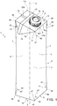
- Number 1 in Figures 1 to 5 indicates as a whole a sealed package according to the present invention, which contains a pourable food product and is obtained from a sheet packaging material 2 as shown in Figure 6 .
- Package 1 comprises a bottom portion 3, a top portion 4 and a main portion 5 interposed between bottom portion 3 and top portion 4 and including a plurality of side wall portions 6, each one delimited by two opposite lateral edge zones 7.
- Main portion 5 is divided from bottom portion 3 by a bottom peripheral outline 8 having an endless configuration defined by a broken line.
- main portion 5 is divided from top portion 4 by a top peripheral outline 9, also having an endless configuration defined by a broken line.
- Bottom portion 3 includes a flat and horizontal bottom panel 10 having a quadrilateral, i.e. rectangular or square (in the example shown rectangular), profile and defining the resting surface of the package itself.
- Bottom panel 10 is delimited by bottom peripheral outline 8 in turn formed by four segments or contour edges, i.e. a bottom front edge 8a, a bottom rear edge 8b parallel to bottom front edge 8a and two bottom side edges 8c, orthogonal to bottom front edge 8a and bottom rear edge 8b.
- bottom front edge 8a and bottom rear edge 8b have the same length; the same applies to bottom side edges 8c, which also have the same length.
- Package 1 extends vertically along a longitudinal direction A, which is orthogonal to bottom panel 10 and along which the total height of the package 1 itself is defined. Longitudinal direction A is also orthogonal to bottom front edge 8a, bottom rear edge 8b and bottom side edges 8c of bottom peripheral outline 8.
- total height means either the height of the package when the latter has a constant height or the maximum height of the package when the latter has a variable height.
- Bottom portion 3 further includes two bottom lateral flaps 11 having substantially triangular configurations and folded in a known manner onto bottom panel 10 ( Figure 4 ).
- Top portion 4 includes a flat and slanted top panel 14 having a quadrilateral, i.e. a square or a rectangular, profile and having a sloping configuration forwards with respect to longitudinal direction A.
- top panel 14 is a rectangle approximating a square.
- Top panel 14 is delimited by top peripheral outline 9 in turn formed by four segments or contour edges, i.e. a top front edge 9a parallel to bottom front edge 8a and bottom rear edge 8b, a top rear edge 9b, parallel to top front edge 9a and arranged higher than the top front edge 9a itself, and two top side edges 9c, orthogonal to top front edge 9a and top rear edge 9b and inclined with respect to longitudinal direction A.
- top peripheral outline 9 in turn formed by four segments or contour edges, i.e. a top front edge 9a parallel to bottom front edge 8a and bottom rear edge 8b, a top rear edge 9b, parallel to top front edge 9a and arranged higher than the top front edge 9a itself, and two top side edges 9c, orthogonal to top front edge 9a and top rear edge 9b and inclined with respect to longitudinal direction A.
- top peripheral outline 9 extends transversally with respect to longitudinal direction A.
- top front edge 9a and top rear edge 9b have the same length; the same applies to top side edges 9c, which also have the same length.
- Top portion 4 further includes two top lateral flaps 15 having substantially triangular configurations and folded in a known manner onto two opposite side wall portions 6 of main portion 5.
- top portion 4 is also provided with an opening device 16 of plastic material placed over and around a removable portion 17 ( Figure 6 ) of the packaging material 2. Opening device 16 is applied onto top panel 14 by conventional fastening systems, such as adhesives, or by micro-flame, electric-current-induction, ultrasound, laser, injection moulding or other heat-sealing techniques.
- main portion 5 of package 1 includes four side wall portions 6 with different profiles and sizes; advantageously, lateral edge zones 7 delimiting side wall portions 6 have rounded configurations.
- a first side wall portion 6, designed to define a front face of package 1 has a substantially rectangular configuration delimited, at bottom and top, by straight bottom front edge 8a and top front edge 9a, and at opposite sides, by respective rounded and convex lateral edge zones 7.
- Each of the other two side wall portions 6 has a profile substantially resembling a rectangular trapezium delimited:
- the two side wall portions 6 having the trapezoidal profiles receive the respective top lateral flaps 15 on their outer surfaces.
- the area of bottom panel 10 is different from the area of a top quadrilateral Q ( Figure 5 ) obtained by projecting, along longitudinal direction A, top panel 14 on a reference plane P ( Figure 3 ) parallel to the bottom panel 10, crossing package 1 and containing top front edge 9a of top peripheral outline 9.
- bottom panel 10 is smaller than the area of top quadrilateral Q.
- the area of bottom panel 10 may be bigger than the area of top quadrilateral Q.
- top quadrilateral Q is a square or a rectangle, in the examples shown a rectangle approximating a square.
- top quadrilateral Q includes a top front segment Q1, corresponding to bottom front edge 8a, a top rear segment Q2, corresponding to bottom rear edge 8b, and two top side segments Q3, respectively corresponding to bottom side edges 8c.
- top side segments Q3 have the same length, which is in turn different from the length of bottom side edges 9c. More specifically, in the example shown, the length of bottom side edges 9c is smaller than the length of top side segments Q3.
- top front segment Q1 and top rear segment Q2 have the same length, which is in turn different from the length of bottom front edge 8a and bottom rear edge 8b.
- the length of bottom front edge 8a and bottom rear edge 8b is greater than the length of top front segment Q1 and top rear segment Q2.
- the packaging material 2 from which package 1 is made is shown in Figure 6 and has a known multilayer structure (not shown) comprising a base layer, e.g. of paper, for stiffness, and a number of lamination layers covering both sides of the base layer.
- a base layer e.g. of paper
- lamination layers covering both sides of the base layer.
- the lamination layers comprise one layer of oxygen-barrier material, e.g. an aluminum foil, and a number of layers of heat-seal plastic material covering both sides of the base layer and both sides of the layer of oxygen-barrier material.
- packaging material 2 comprises one layer of heat-seal plastic material, one layer of oxygen-barrier material, another layer of heat-seal plastic material, the base layer, and one or more additional layers of heat-seal plastic material.
- the letter M in Figure 6 indicates a basic unit of packaging material 2, by which to produce package 1, and which may be a precut blank, or a portion of a web of packaging material comprising a succession of basic units M.
- basic unit M is folded on a known forming spindle (not shown), is filled with the food product, and is sealed at the top to form the final package.
- the web of packaging material 2 comprising a succession of basic units M, is:
- package 1 After completion of these operations, package 1 has:
- bottom panel 10 is crossed by bottom transverse sealing band 18 and by an end portion 20a of longitudinal sealing band 20 extending perpendicularly from the bottom transverse sealing band 18.
- top panel 14 is crossed by top transverse sealing band 19 and by an end portion 20b of longitudinal sealing band 20 extending perpendicularly from the top transverse sealing band 19 and opposite to end portion 20a; in greater detail, top transverse sealing band 19 divides top panel 14 into two zones 14a, 14b and end portion 20b of longitudinal sealing band 20 extends on one (14b) of such zones 14a, 14b from an intermediate portion of the top transverse sealing band 19.
- top transverse sealing band 19 is folded on zone 14b and end portion 20b of longitudinal sealing band 20; in this way, zone 14a has a bigger area than zone 14b and is therefore more suitable for receiving removable portion 17 and opening device 16.
- removable portion 17 has a circular profile and is designed to be at least partly detached in use from the rest of the packaging material by opening device 16 to free a pour opening through which to pour out the product.
- Removable portion 17 is formed on packaging material 2 prior to folding and sealing the packaging material 2 itself to form the finished package.
- removable portion 17 comprises a so-called “prelaminated” hole, i.e. a circular hole formed through the base layer only of packaging material 2 and covered, when the packaging material 2 itself is laminated, with the layers of heat-seal plastic material and oxygen-barrier material, which adhere to one another at the hole.
- prelaminated hole i.e. a circular hole formed through the base layer only of packaging material 2 and covered, when the packaging material 2 itself is laminated, with the layers of heat-seal plastic material and oxygen-barrier material, which adhere to one another at the hole.
- basic unit M of packaging material 2 has a rectangular configuration and is delimited by:
- Basic unit M of packaging material 2 comprises a number of crease lines defining respective fold lines, along which the packaging material 2 itself is folded to form the finished package 1.
- basic unit M comprises two transversal crease lines 25, 26 extending transversally with respect to longitudinal direction A and dividing the basic unit M itself into:
- Transversal crease line 25 extends parallel to bottom boundary edge 23 and top boundary edge 24 and is arranged closer to bottom boundary edge 23 than transversal crease line 26. Transversal crease line 25 is configured to define bottom peripheral outline 8 of package 1.
- transversal crease line 25 includes:
- Transversal crease line 26 is arranged closer to top boundary edge 24 than transversal crease line 25 and is configured to define top peripheral outline 9 of package 1.
- transversal crease line 26 has a broken-line shape with:
- top side portions 26c converge towards top central portion 26a.
- Basic unit M includes two further transversal crease lines 32, 33 extending parallel to direction B and placed near bottom boundary edge 23 and top boundary edge 24, respectively; transversal crease lines 32, 33 delimit with bottom boundary edge 23 and top boundary edge 24 respective bottom transversal sealing area 34 and top transversal sealing area 35 configured to define bottom transversal sealing band 18 and top transversal sealing band 19 of package 1.
- Bottom crease pattern 28 is designed to produce bottom panel 10 and bottom lateral flaps 11 of package 1.
- bottom crease pattern 28 includes, in a known manner, four longitudinal crease lines 36a, 36b parallel to longitudinal direction A and extending between transversal crease lines 25 and 32.
- Longitudinal crease lines 36b are the most internal ones, whilst longitudinal crease lines 36a are located near opposite side boundary edges 22; the area between longitudinal crease lines 36b as well as the areas delimited by longitudinal crease lines 36a with the respective side boundary edges 22 are configured to define bottom panel 10 of package 1.
- bottom crease pattern 28 further includes two additional crease lines 37, 38 inclined with respect to both longitudinal direction A and transversal direction B.
- each pair of additional crease lines 37, 38 of each pair have one end in common located on transversal crease line 32 and opposite ends located at the intersection points between transversal crease line 25 and longitudinal crease lines 36a and 36b, respectively.
- each pair of additional crease lines 37, 38 delimits a triangle 39 with the segment of transversal crease line 25 comprised between the additional crease lines 37, 38 themselves.
- Each area between longitudinal crease lines 36a and 36b is configured to define one respective bottom lateral flap 11 of package 1.
- Top crease pattern 30 is designed to produce top panel 14 and top lateral flaps 15 of package 1.
- top crease pattern 30 includes four longitudinal crease lines 40a, 40b parallel to longitudinal direction A and extending between transversal crease lines 26 and 33.
- Longitudinal crease lines 40b are the most internal ones, whilst longitudinal crease lines 40a are located near opposite side boundary edges 22; the area between longitudinal crease lines 40b as well as the areas delimited by longitudinal crease lines 40a with the respective side boundary edges 22 are configured to define top panel 14 of package 1.
- Removable portion 17 is formed in the area of top region 29 comprised between longitudinal crease lines 40b.
- top crease pattern 30 further includes two additional crease lines 41, 42 inclined with respect to both longitudinal direction A and transversal direction B.
- the additional crease lines 41, 42 of each pair have one end in common located on transversal crease line 33 and opposite ends located at, or adjacent to, the opposite ends of the respective inclined top side portion 26c of transversal crease line 26.
- each pair of additional crease lines 41, 42 delimits a triangle 43 with the respective top side portion 26c of transversal creased line 26.
- Each area between longitudinal crease lines 40a and 40b is configured to define one respective top lateral flap 15 of package 1.
- the length of top central portion 26a of transversal crease line 26 is different from the length of bottom central portion 25a of transversal crease line 25; in addition, the length of each of bottom side portions 25c of transversal crease line 25 is also different from the length of the projection R, parallel to longitudinal direction A, of each of top side portions 26c of transversal crease line 26 on a reference line S parallel to transversal crease line 25 and containing top central portion 26a.
- top central portion 26a is smaller than the length of bottom central portion 25a; in a different manner, the length of each projection R is greater than the length of the corresponding bottom side portion 25c.
- the length of bottom central portion 25a corresponds to the length of the segment of transversal crease line 32 comprised between longitudinal crease lines 36b; in a completely analogous manner, the length of top central portion 26a corresponds to the length of the segment of transversal crease line 33 comprised between longitudinal crease lines 40b.
- bottom side portions 25c whose lengths correspond to the lengths of the respective segments of transversal crease line 32 comprised between each pair of longitudinal crease lines 36a and 36b.
- the lengths of projections R correspond to the lengths of the respective segments of transversal crease line 33 comprised between each pair of longitudinal crease lines 40a and 40b.
- top front segment Q1 and top rear segment Q2 of top quadrilateral Q corresponds to the length of top central portion 26a; in an analogous manner, the length of top side segments Q3 of top quadrilateral Q corresponds to the length of projections R.
- intermediate region 31 includes a central transversal band 44 having a uniform structure, i.e. lacking any creasing or weakening, and crossing the areas of the intermediate region 31 itself designed to form the respective lateral edge zones 7 of side wall portions 6 of package 1.
- intermediate region 31 of basic unit M further comprises a plurality of V-shaped crease lines 45 having respective vertices 46 located on or adjacent to the transversal crease lines 25, 26 and at given points thereof designed to define the opposite ends of respective lateral edge zones 7 delimiting the side wall portions 6 of package 1; each V-shaped crease line 45 extends from and in proximity of the respective transversal crease line 25, 26 up to central transversal band 44 and comprises two legs 47 diverging from the respective vertex 46.
- each V-shaped crease line 45 extends from the respective transversal crease line 25, 26 towards the other transversal crease line 26, 25 and has a size, parallel to longitudinal direction A, greater than zero and smaller than one fourth, preferably smaller than one tenth, of the total height of intermediate region 31 measured parallel to the longitudinal direction A itself.
- total height of intermediate region 31 corresponds to the total height of the package.
- each V-shaped crease line 45 extending from transversal crease line 25 and the corresponding V-shaped crease line 45 extending from transversal crease line 26 are spaced apart parallel to longitudinal direction A.
- each V-shaped crease line 45 has a size, parallel to longitudinal direction A, smaller than the maximum height of bottom region 27 or top region 29 measured parallel to the longitudinal direction A itself.
- each leg of the V-shaped crease lines 45 has a length smaller than the maximum length of the heights of triangles 39, 43 with reference to their bases on respective transversal crease lines 25, 26.
- each V-shaped crease line 45 has a size, parallel to longitudinal direction A, substantially equal to one fourteenth of the total height of intermediate region 31 measured parallel to the longitudinal direction A itself.
- V-shaped crease lines 45 are the only crease lines present in intermediate region 31 at the areas designed to define lateral edge zones 7 between side wall portions 6 of package 1.
- V-shaped crease lines 45 perform the function of easing folding of the packaging material 2 at the corners between lateral edge zones 7 of side wall portions 6 and bottom peripheral outline 8 and top peripheral outline 9 without affecting the round configuration of lateral edge zones 7.
- legs 47 of each V-shaped crease line 45 are rectilinear or straight; as a possible alternative not shown, legs 47 of each V-shaped crease line 45 may also be curved, preferably with their concavities facing one another.
- legs 47 of each V-shaped crease line 45 delimit an angle comprised between 45° and 90°.
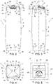
- Number 1' in Figure 7 indicates as a whole a different embodiment of a sealed package according to the present invention and obtained by a basic unit M' ( Figure 8 ) of sheet packaging material 2.
- Package 1' being similar to package 1, the following description is limited to the differences between them, and using the same references, where possible, for identical or corresponding parts; the same applies for basic units M' and M.
- package 1' differs from package 1 only in that lateral edge zones 7 between side wall portions 6 are defined by respective longitudinal crease lines 50 extending between transversal crease lines 25 and 26.
- Longitudinal crease lines 50 are slightly slanted with respect to longitudinal direction A due to the different lengths between bottom central portion 25a and top central portions 26a of transversal crease lines 25, 26 as well as between bottom side portions 25c of transversal crease line 25 and respective projections R on reference line S.
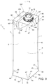
- Number 1 in Figure 9 indicates as a whole a different embodiment of a sealed package according to the present invention and obtained by a basic unit M" ( Figure 10 ) of sheet packaging material 2.
- Package 1 being similar to package 1, the following description is limited to the differences between them, and using the same references, where possible, for identical or corresponding parts; the same applies for basic units M" and M.
- package 1" differs from package 1 only by having a top panel 14'' that extends horizontally and parallel to bottom panel 10.
- top panel 14'' is delimited by a top peripheral outline 9'' (formed by edges 9a'', 9b'', 9c'') parallel to bottom peripheral outline 8 and deriving by a transversal crease line 26'' also parallel to transversal crease line 25 and to transversal direction B.
- top panel 14'' extends entirely on reference plane P and therefore the projection of top panel 14'' on this latter plane, i.e. top quadrilateral Q, coincides with the top panel 14" itself.
- Number 1''' in Figure 11 indicates as a whole a different embodiment of a sealed package according to the present invention and obtained by a basic unit M''' ( Figure 12 ) of sheet packaging material 2.
- Package 1''' being similar to package 1", the following description is limited to the differences between them, and using the same references, where possible, for identical or corresponding parts; the same applies for basic units M''' and M".
- package 1''' differs from package 1'' only in that lateral edge zones 7 between side wall portions 6 are defined by respective longitudinal crease lines 50 extending between transversal crease lines 25 and 26. Even in this case, longitudinal crease lines 50 are slightly slanted with respect to longitudinal direction A due to the different lengths between bottom central portion 25a and top central portion 26a'' of transversal crease lines 25, 26'' as well as between bottom side portions 25c and top side portion 26c'' of the same transversal crease lines 25, 26".
Landscapes
- Engineering & Computer Science (AREA)
- Mechanical Engineering (AREA)
- Cartons (AREA)
- Packages (AREA)
- Packging For Living Organisms, Food Or Medicinal Products That Are Sensitive To Environmental Conditiond (AREA)
Priority Applications (1)
| Application Number | Priority Date | Filing Date | Title |
|---|---|---|---|
| EP23194824.1A EP4279408B1 (de) | 2018-04-20 | 2019-04-15 | Versiegelte verpackung mit einem giessbaren lebensmittelprodukt und folienverpackungsmaterial zur herstellung einer versiegelten verpackung mit einem giessbaren lebensmittelprodukt |
Applications Claiming Priority (1)
| Application Number | Priority Date | Filing Date | Title |
|---|---|---|---|
| EP18168373 | 2018-04-20 |
Related Child Applications (2)
| Application Number | Title | Priority Date | Filing Date |
|---|---|---|---|
| EP23194824.1A Division EP4279408B1 (de) | 2018-04-20 | 2019-04-15 | Versiegelte verpackung mit einem giessbaren lebensmittelprodukt und folienverpackungsmaterial zur herstellung einer versiegelten verpackung mit einem giessbaren lebensmittelprodukt |
| EP23194824.1A Division-Into EP4279408B1 (de) | 2018-04-20 | 2019-04-15 | Versiegelte verpackung mit einem giessbaren lebensmittelprodukt und folienverpackungsmaterial zur herstellung einer versiegelten verpackung mit einem giessbaren lebensmittelprodukt |
Publications (3)
| Publication Number | Publication Date |
|---|---|
| EP3556673A1 true EP3556673A1 (de) | 2019-10-23 |
| EP3556673B1 EP3556673B1 (de) | 2023-10-11 |
| EP3556673C0 EP3556673C0 (de) | 2023-10-11 |
Family
ID=62044521
Family Applications (2)
| Application Number | Title | Priority Date | Filing Date |
|---|---|---|---|
| EP19169271.4A Active EP3556673B1 (de) | 2018-04-20 | 2019-04-15 | Versiegelte packung für ein giessbares lebensmittelprodukt und folienverpackungsmaterial zur herstellung einer versiegelten packung für ein giessbares lebensmittelprodukt |
| EP23194824.1A Active EP4279408B1 (de) | 2018-04-20 | 2019-04-15 | Versiegelte verpackung mit einem giessbaren lebensmittelprodukt und folienverpackungsmaterial zur herstellung einer versiegelten verpackung mit einem giessbaren lebensmittelprodukt |
Family Applications After (1)
| Application Number | Title | Priority Date | Filing Date |
|---|---|---|---|
| EP23194824.1A Active EP4279408B1 (de) | 2018-04-20 | 2019-04-15 | Versiegelte verpackung mit einem giessbaren lebensmittelprodukt und folienverpackungsmaterial zur herstellung einer versiegelten verpackung mit einem giessbaren lebensmittelprodukt |
Country Status (7)
| Country | Link |
|---|---|
| US (1) | US20210237925A1 (de) |
| EP (2) | EP3556673B1 (de) |
| JP (2) | JP7436384B2 (de) |
| CN (2) | CN110386317A (de) |
| ES (2) | ES3037948T3 (de) |
| MX (2) | MX2020010758A (de) |
| WO (1) | WO2019201860A1 (de) |
Families Citing this family (5)
| Publication number | Priority date | Publication date | Assignee | Title |
|---|---|---|---|---|
| EP3556673B1 (de) * | 2018-04-20 | 2023-10-11 | Tetra Laval Holdings & Finance S.A. | Versiegelte packung für ein giessbares lebensmittelprodukt und folienverpackungsmaterial zur herstellung einer versiegelten packung für ein giessbares lebensmittelprodukt |
| WO2020000092A1 (en) | 2018-06-27 | 2020-01-02 | Algernon Pharmaceuticals Inc. | The use of actarit in the prophylaxis or treatment of renal fibrosis or kidney disease |
| JP7439045B2 (ja) * | 2018-07-16 | 2024-02-27 | テトラ ラバル ホールディングス アンド ファイナンス エス エイ | 注入可能な食品用のシールされた包装容器を製造するためのシート状包装材料、注入可能な食品用のシールされた包装容器、及び注入可能な食品用のシールされた包装容器を製造する方法 |
| WO2022171856A1 (en) | 2021-02-15 | 2022-08-18 | Tetra Laval Holdings & Finance S.A. | A method for assessing quality of a transversal sealing of a food package |
| US20260021930A1 (en) * | 2022-08-02 | 2026-01-22 | Tetra Laval Holdings & Finance S.A. | Packaging blank for forming a package and package formed from a packaging blank |
Citations (4)
| Publication number | Priority date | Publication date | Assignee | Title |
|---|---|---|---|---|
| EP2392517A1 (de) * | 2010-06-07 | 2011-12-07 | Tetra Laval Holdings & Finance S.A. | Versiegelte Packung für gießbare Lebensmittelprodukte und Verpackungsmaterial zur Herstellung von versiegelten Packungen für gießbare Lebensmittelprodukte |
| EP2650222A1 (de) * | 2010-12-07 | 2013-10-16 | Tetra Laval Holdings & Finance SA | Herstellungsverfahren für einen verpackungsbehälter und verpackungsbehälter |
| WO2017001162A1 (de) * | 2015-06-30 | 2017-01-05 | Sig Technology Ag | Ausgiesselement für eine verpackung sowie verbundverpackung mit einem solchen ausgiesselement |
| WO2017025922A2 (en) * | 2015-08-12 | 2017-02-16 | Ipi S.R.L. | Container for pourable products |
Family Cites Families (20)
| Publication number | Priority date | Publication date | Assignee | Title |
|---|---|---|---|---|
| US1342770A (en) * | 1917-10-02 | 1920-06-08 | Paper Bottle And Can Company I | Paper bottle |
| US2643815A (en) * | 1951-01-26 | 1953-06-30 | Komeo Oscar | Sanitary milk carton |
| US3369727A (en) * | 1966-06-17 | 1968-02-20 | Timmy E. Wright | Container |
| US3731872A (en) * | 1971-05-14 | 1973-05-08 | Union Camp Corp | Four-sided taper box |
| US4498585A (en) * | 1983-12-23 | 1985-02-12 | International Paper Company | Denesting paperboard container |
| US4730766A (en) * | 1985-12-20 | 1988-03-15 | Continental Bondware, Inc. | Sealing of void area at the top of cup bead of hot melt |
| US5358175A (en) * | 1993-03-17 | 1994-10-25 | Dopaco, Inc. | Cup container with intergral closure |
| FR2734541B1 (fr) * | 1995-05-24 | 1997-08-14 | Michel Claude | Corps tubulaire pliable, et enveloppes, notamment boite ou vase de fleurs jetable, munies d'un tel corps |
| DE29700608U1 (de) * | 1997-01-15 | 1997-02-27 | E. Gundlach Verpackung + Display GmbH, 33813 Oerlinghausen | Behälter |
| US6182887B1 (en) * | 1999-04-16 | 2001-02-06 | Tetra Laval Holdings & Finance, Sa | Package with extended top panel and a blank therefor |
| US7017796B2 (en) * | 2000-07-31 | 2006-03-28 | Tetra Laval Holdings & Finance S.A. | Method of manufacturing paper packaging container and paper packaging container |
| KR20020097097A (ko) * | 2002-11-12 | 2002-12-31 | 이정민 | 다단 적층이 가능한 형태의 용기 제작 방법 및 그 구조 |
| JP2005035583A (ja) * | 2003-07-18 | 2005-02-10 | Dainippon Printing Co Ltd | 変形液体用紙容器 |
| JP2005035580A (ja) * | 2003-07-18 | 2005-02-10 | Dainippon Printing Co Ltd | 液体用紙容器 |
| RU90415U1 (ru) * | 2009-06-01 | 2010-01-10 | Максим Анатольевич Савин | Заготовка контейнера для жидких продуктов |
| CN103228542B (zh) * | 2010-12-06 | 2016-08-10 | 利乐拉瓦尔集团及财务有限公司 | 包装容器的制造方法及包装容器 |
| ITRM20130052A1 (it) * | 2013-01-29 | 2014-07-30 | Ipi Srl | Contenitore confezionato e relativo foglio matrice di confezionamento. |
| EP3228553A1 (de) * | 2016-04-04 | 2017-10-11 | SIG Technology AG | Verbundpackung, packungslaminat und packungsmantelrohling für eine verbundpackung |
| JP6618085B2 (ja) * | 2017-03-31 | 2019-12-11 | 日本製紙株式会社 | 紙容器 |
| EP3556673B1 (de) * | 2018-04-20 | 2023-10-11 | Tetra Laval Holdings & Finance S.A. | Versiegelte packung für ein giessbares lebensmittelprodukt und folienverpackungsmaterial zur herstellung einer versiegelten packung für ein giessbares lebensmittelprodukt |
-
2019
- 2019-04-15 EP EP19169271.4A patent/EP3556673B1/de active Active
- 2019-04-15 WO PCT/EP2019/059680 patent/WO2019201860A1/en not_active Ceased
- 2019-04-15 JP JP2020557909A patent/JP7436384B2/ja active Active
- 2019-04-15 ES ES23194824T patent/ES3037948T3/es active Active
- 2019-04-15 ES ES19169271T patent/ES2963263T3/es active Active
- 2019-04-15 MX MX2020010758A patent/MX2020010758A/es unknown
- 2019-04-15 EP EP23194824.1A patent/EP4279408B1/de active Active
- 2019-04-15 US US17/048,958 patent/US20210237925A1/en active Pending
- 2019-04-17 CN CN201910315669.2A patent/CN110386317A/zh active Pending
- 2019-04-17 CN CN201920518124.7U patent/CN210761729U/zh active Active
-
2020
- 2020-10-12 MX MX2024009642A patent/MX2024009642A/es unknown
-
2024
- 2024-02-08 JP JP2024017659A patent/JP2024045472A/ja active Pending
Patent Citations (4)
| Publication number | Priority date | Publication date | Assignee | Title |
|---|---|---|---|---|
| EP2392517A1 (de) * | 2010-06-07 | 2011-12-07 | Tetra Laval Holdings & Finance S.A. | Versiegelte Packung für gießbare Lebensmittelprodukte und Verpackungsmaterial zur Herstellung von versiegelten Packungen für gießbare Lebensmittelprodukte |
| EP2650222A1 (de) * | 2010-12-07 | 2013-10-16 | Tetra Laval Holdings & Finance SA | Herstellungsverfahren für einen verpackungsbehälter und verpackungsbehälter |
| WO2017001162A1 (de) * | 2015-06-30 | 2017-01-05 | Sig Technology Ag | Ausgiesselement für eine verpackung sowie verbundverpackung mit einem solchen ausgiesselement |
| WO2017025922A2 (en) * | 2015-08-12 | 2017-02-16 | Ipi S.R.L. | Container for pourable products |
Also Published As
| Publication number | Publication date |
|---|---|
| EP4279408A2 (de) | 2023-11-22 |
| EP4279408B1 (de) | 2025-07-02 |
| MX2024009642A (es) | 2024-08-19 |
| EP3556673B1 (de) | 2023-10-11 |
| BR112020018388A2 (pt) | 2020-12-22 |
| ES3037948T3 (en) | 2025-10-08 |
| MX2020010758A (es) | 2020-11-09 |
| US20210237925A1 (en) | 2021-08-05 |
| JP2021522114A (ja) | 2021-08-30 |
| JP7436384B2 (ja) | 2024-02-21 |
| EP4279408A3 (de) | 2024-03-20 |
| JP2024045472A (ja) | 2024-04-02 |
| EP4279408C0 (de) | 2025-07-02 |
| EP3556673C0 (de) | 2023-10-11 |
| WO2019201860A1 (en) | 2019-10-24 |
| CN110386317A (zh) | 2019-10-29 |
| CN210761729U (zh) | 2020-06-16 |
| ES2963263T3 (es) | 2024-03-26 |
Similar Documents
| Publication | Publication Date | Title |
|---|---|---|
| US12037167B2 (en) | Sheet packaging material for producing a sealed package containing a pourable food product and a sealed package obtained from a sheet packaging material | |
| US11667428B2 (en) | Sheet packaging matertial for producing a sealed package containing a pourable product and a package obtained therefrom | |
| US7325719B2 (en) | Gable-top package for pourable food products | |
| EP3556673B1 (de) | Versiegelte packung für ein giessbares lebensmittelprodukt und folienverpackungsmaterial zur herstellung einer versiegelten packung für ein giessbares lebensmittelprodukt | |
| EP3219633A1 (de) | Verpackungsfolienmaterial | |
| US20160325872A1 (en) | Sealed package for pourable food products and a basic unit of sheet packaging material for producing sealed packages for pourable food products | |
| US11932461B2 (en) | Sheet packaging material for producing sealed packages for liquid food products | |
| RU2785517C2 (ru) | Листовой упаковочный материал для изготовления герметичной упаковки, содержащей наливной пищевой продукт, и герметичная упаковка, полученная из листового упаковочного материала | |
| EP4458708B1 (de) | Verpackungszuschnitt zur herstellung einer verpackung und aus einem verpackungszuschnitt hergestellte verpackung | |
| RU2785516C2 (ru) | Герметичная упаковка, содержащая наливной пищевой продукт, и листовой упаковочный материал для изготовления герметичной упаковки, содержащей наливной пищевой продукт | |
| US20260021930A1 (en) | Packaging blank for forming a package and package formed from a packaging blank | |
| EP4317002A1 (de) | Verpackungszuschnitt zum formen einer verpackung und verpackung aus einem verpackungszuschnitt |
Legal Events
| Date | Code | Title | Description |
|---|---|---|---|
| PUAI | Public reference made under article 153(3) epc to a published international application that has entered the european phase |
Free format text: ORIGINAL CODE: 0009012 |
|
| STAA | Information on the status of an ep patent application or granted ep patent |
Free format text: STATUS: THE APPLICATION HAS BEEN PUBLISHED |
|
| AK | Designated contracting states |
Kind code of ref document: A1 Designated state(s): AL AT BE BG CH CY CZ DE DK EE ES FI FR GB GR HR HU IE IS IT LI LT LU LV MC MK MT NL NO PL PT RO RS SE SI SK SM TR |
|
| AX | Request for extension of the european patent |
Extension state: BA ME |
|
| STAA | Information on the status of an ep patent application or granted ep patent |
Free format text: STATUS: REQUEST FOR EXAMINATION WAS MADE |
|
| 17P | Request for examination filed |
Effective date: 20200423 |
|
| RBV | Designated contracting states (corrected) |
Designated state(s): AL AT BE BG CH CY CZ DE DK EE ES FI FR GB GR HR HU IE IS IT LI LT LU LV MC MK MT NL NO PL PT RO RS SE SI SK SM TR |
|
| STAA | Information on the status of an ep patent application or granted ep patent |
Free format text: STATUS: EXAMINATION IS IN PROGRESS |
|
| 17Q | First examination report despatched |
Effective date: 20220517 |
|
| GRAP | Despatch of communication of intention to grant a patent |
Free format text: ORIGINAL CODE: EPIDOSNIGR1 |
|
| STAA | Information on the status of an ep patent application or granted ep patent |
Free format text: STATUS: GRANT OF PATENT IS INTENDED |
|
| INTG | Intention to grant announced |
Effective date: 20230616 |
|
| GRAS | Grant fee paid |
Free format text: ORIGINAL CODE: EPIDOSNIGR3 |
|
| GRAA | (expected) grant |
Free format text: ORIGINAL CODE: 0009210 |
|
| STAA | Information on the status of an ep patent application or granted ep patent |
Free format text: STATUS: THE PATENT HAS BEEN GRANTED |
|
| AK | Designated contracting states |
Kind code of ref document: B1 Designated state(s): AL AT BE BG CH CY CZ DE DK EE ES FI FR GB GR HR HU IE IS IT LI LT LU LV MC MK MT NL NO PL PT RO RS SE SI SK SM TR |
|
| REG | Reference to a national code |
Ref country code: GB Ref legal event code: FG4D |
|
| REG | Reference to a national code |
Ref country code: CH Ref legal event code: EP |
|
| REG | Reference to a national code |
Ref country code: DE Ref legal event code: R096 Ref document number: 602019038992 Country of ref document: DE |
|
| REG | Reference to a national code |
Ref country code: IE Ref legal event code: FG4D |
|
| U01 | Request for unitary effect filed |
Effective date: 20231031 |
|
| U07 | Unitary effect registered |
Designated state(s): AT BE BG DE DK EE FI FR IT LT LU LV MT NL PT SE SI Effective date: 20231106 |
|
| REG | Reference to a national code |
Ref country code: ES Ref legal event code: FG2A Ref document number: 2963263 Country of ref document: ES Kind code of ref document: T3 Effective date: 20240326 |
|
| PG25 | Lapsed in a contracting state [announced via postgrant information from national office to epo] |
Ref country code: GR Free format text: LAPSE BECAUSE OF FAILURE TO SUBMIT A TRANSLATION OF THE DESCRIPTION OR TO PAY THE FEE WITHIN THE PRESCRIBED TIME-LIMIT Effective date: 20240112 |
|
| PG25 | Lapsed in a contracting state [announced via postgrant information from national office to epo] |
Ref country code: IS Free format text: LAPSE BECAUSE OF FAILURE TO SUBMIT A TRANSLATION OF THE DESCRIPTION OR TO PAY THE FEE WITHIN THE PRESCRIBED TIME-LIMIT Effective date: 20240211 |
|
| PG25 | Lapsed in a contracting state [announced via postgrant information from national office to epo] |
Ref country code: IS Free format text: LAPSE BECAUSE OF FAILURE TO SUBMIT A TRANSLATION OF THE DESCRIPTION OR TO PAY THE FEE WITHIN THE PRESCRIBED TIME-LIMIT Effective date: 20240211 Ref country code: GR Free format text: LAPSE BECAUSE OF FAILURE TO SUBMIT A TRANSLATION OF THE DESCRIPTION OR TO PAY THE FEE WITHIN THE PRESCRIBED TIME-LIMIT Effective date: 20240112 |
|
| PG25 | Lapsed in a contracting state [announced via postgrant information from national office to epo] |
Ref country code: RS Free format text: LAPSE BECAUSE OF FAILURE TO SUBMIT A TRANSLATION OF THE DESCRIPTION OR TO PAY THE FEE WITHIN THE PRESCRIBED TIME-LIMIT Effective date: 20231011 Ref country code: PL Free format text: LAPSE BECAUSE OF FAILURE TO SUBMIT A TRANSLATION OF THE DESCRIPTION OR TO PAY THE FEE WITHIN THE PRESCRIBED TIME-LIMIT Effective date: 20231011 Ref country code: NO Free format text: LAPSE BECAUSE OF FAILURE TO SUBMIT A TRANSLATION OF THE DESCRIPTION OR TO PAY THE FEE WITHIN THE PRESCRIBED TIME-LIMIT Effective date: 20240111 Ref country code: HR Free format text: LAPSE BECAUSE OF FAILURE TO SUBMIT A TRANSLATION OF THE DESCRIPTION OR TO PAY THE FEE WITHIN THE PRESCRIBED TIME-LIMIT Effective date: 20231011 |
|
| U20 | Renewal fee for the european patent with unitary effect paid |
Year of fee payment: 6 Effective date: 20240429 |
|
| REG | Reference to a national code |
Ref country code: DE Ref legal event code: R097 Ref document number: 602019038992 Country of ref document: DE |
|
| PG25 | Lapsed in a contracting state [announced via postgrant information from national office to epo] |
Ref country code: CZ Free format text: LAPSE BECAUSE OF FAILURE TO SUBMIT A TRANSLATION OF THE DESCRIPTION OR TO PAY THE FEE WITHIN THE PRESCRIBED TIME-LIMIT Effective date: 20231011 |
|
| PG25 | Lapsed in a contracting state [announced via postgrant information from national office to epo] |
Ref country code: SK Free format text: LAPSE BECAUSE OF FAILURE TO SUBMIT A TRANSLATION OF THE DESCRIPTION OR TO PAY THE FEE WITHIN THE PRESCRIBED TIME-LIMIT Effective date: 20231011 |
|
| PG25 | Lapsed in a contracting state [announced via postgrant information from national office to epo] |
Ref country code: SM Free format text: LAPSE BECAUSE OF FAILURE TO SUBMIT A TRANSLATION OF THE DESCRIPTION OR TO PAY THE FEE WITHIN THE PRESCRIBED TIME-LIMIT Effective date: 20231011 Ref country code: SK Free format text: LAPSE BECAUSE OF FAILURE TO SUBMIT A TRANSLATION OF THE DESCRIPTION OR TO PAY THE FEE WITHIN THE PRESCRIBED TIME-LIMIT Effective date: 20231011 Ref country code: RO Free format text: LAPSE BECAUSE OF FAILURE TO SUBMIT A TRANSLATION OF THE DESCRIPTION OR TO PAY THE FEE WITHIN THE PRESCRIBED TIME-LIMIT Effective date: 20231011 Ref country code: CZ Free format text: LAPSE BECAUSE OF FAILURE TO SUBMIT A TRANSLATION OF THE DESCRIPTION OR TO PAY THE FEE WITHIN THE PRESCRIBED TIME-LIMIT Effective date: 20231011 |
|
| PLBE | No opposition filed within time limit |
Free format text: ORIGINAL CODE: 0009261 |
|
| STAA | Information on the status of an ep patent application or granted ep patent |
Free format text: STATUS: NO OPPOSITION FILED WITHIN TIME LIMIT |
|
| 26N | No opposition filed |
Effective date: 20240712 |
|
| PG25 | Lapsed in a contracting state [announced via postgrant information from national office to epo] |
Ref country code: MC Free format text: LAPSE BECAUSE OF FAILURE TO SUBMIT A TRANSLATION OF THE DESCRIPTION OR TO PAY THE FEE WITHIN THE PRESCRIBED TIME-LIMIT Effective date: 20231011 |
|
| PG25 | Lapsed in a contracting state [announced via postgrant information from national office to epo] |
Ref country code: MC Free format text: LAPSE BECAUSE OF FAILURE TO SUBMIT A TRANSLATION OF THE DESCRIPTION OR TO PAY THE FEE WITHIN THE PRESCRIBED TIME-LIMIT Effective date: 20231011 |
|
| REG | Reference to a national code |
Ref country code: CH Ref legal event code: PL |
|
| GBPC | Gb: european patent ceased through non-payment of renewal fee |
Effective date: 20240415 |
|
| PG25 | Lapsed in a contracting state [announced via postgrant information from national office to epo] |
Ref country code: GB Free format text: LAPSE BECAUSE OF NON-PAYMENT OF DUE FEES Effective date: 20240415 |
|
| PG25 | Lapsed in a contracting state [announced via postgrant information from national office to epo] |
Ref country code: GB Free format text: LAPSE BECAUSE OF NON-PAYMENT OF DUE FEES Effective date: 20240415 Ref country code: CH Free format text: LAPSE BECAUSE OF NON-PAYMENT OF DUE FEES Effective date: 20240430 |
|
| PG25 | Lapsed in a contracting state [announced via postgrant information from national office to epo] |
Ref country code: IE Free format text: LAPSE BECAUSE OF NON-PAYMENT OF DUE FEES Effective date: 20240415 |
|
| U20 | Renewal fee for the european patent with unitary effect paid |
Year of fee payment: 7 Effective date: 20250424 |
|
| PGFP | Annual fee paid to national office [announced via postgrant information from national office to epo] |
Ref country code: ES Payment date: 20250513 Year of fee payment: 7 |
|
| PG25 | Lapsed in a contracting state [announced via postgrant information from national office to epo] |
Ref country code: CY Free format text: LAPSE BECAUSE OF FAILURE TO SUBMIT A TRANSLATION OF THE DESCRIPTION OR TO PAY THE FEE WITHIN THE PRESCRIBED TIME-LIMIT; INVALID AB INITIO Effective date: 20190415 |
|
| PG25 | Lapsed in a contracting state [announced via postgrant information from national office to epo] |
Ref country code: HU Free format text: LAPSE BECAUSE OF FAILURE TO SUBMIT A TRANSLATION OF THE DESCRIPTION OR TO PAY THE FEE WITHIN THE PRESCRIBED TIME-LIMIT; INVALID AB INITIO Effective date: 20190415 |