EP3556535B1 - Spritzgusseinheit mit durchlassöffnung eines dezentrierten stutzens - Google Patents
Spritzgusseinheit mit durchlassöffnung eines dezentrierten stutzens Download PDFInfo
- Publication number
- EP3556535B1 EP3556535B1 EP19168247.5A EP19168247A EP3556535B1 EP 3556535 B1 EP3556535 B1 EP 3556535B1 EP 19168247 A EP19168247 A EP 19168247A EP 3556535 B1 EP3556535 B1 EP 3556535B1
- Authority
- EP
- European Patent Office
- Prior art keywords
- face
- mould
- mold
- moulding
- axis
- Prior art date
- Legal status (The legal status is an assumption and is not a legal conclusion. Google has not performed a legal analysis and makes no representation as to the accuracy of the status listed.)
- Active
Links
Images


Classifications
-
- B—PERFORMING OPERATIONS; TRANSPORTING
- B29—WORKING OF PLASTICS; WORKING OF SUBSTANCES IN A PLASTIC STATE IN GENERAL
- B29C—SHAPING OR JOINING OF PLASTICS; SHAPING OF MATERIAL IN A PLASTIC STATE, NOT OTHERWISE PROVIDED FOR; AFTER-TREATMENT OF THE SHAPED PRODUCTS, e.g. REPAIRING
- B29C49/00—Blow-moulding, i.e. blowing a preform or parison to a desired shape within a mould; Apparatus therefor
- B29C49/42—Component parts, details or accessories; Auxiliary operations
- B29C49/48—Moulds
-
- B—PERFORMING OPERATIONS; TRANSPORTING
- B29—WORKING OF PLASTICS; WORKING OF SUBSTANCES IN A PLASTIC STATE IN GENERAL
- B29C—SHAPING OR JOINING OF PLASTICS; SHAPING OF MATERIAL IN A PLASTIC STATE, NOT OTHERWISE PROVIDED FOR; AFTER-TREATMENT OF THE SHAPED PRODUCTS, e.g. REPAIRING
- B29C49/00—Blow-moulding, i.e. blowing a preform or parison to a desired shape within a mould; Apparatus therefor
- B29C49/28—Blow-moulding apparatus
- B29C49/30—Blow-moulding apparatus having movable moulds or mould parts
- B29C49/36—Blow-moulding apparatus having movable moulds or mould parts rotatable about one axis
-
- B—PERFORMING OPERATIONS; TRANSPORTING
- B29—WORKING OF PLASTICS; WORKING OF SUBSTANCES IN A PLASTIC STATE IN GENERAL
- B29C—SHAPING OR JOINING OF PLASTICS; SHAPING OF MATERIAL IN A PLASTIC STATE, NOT OTHERWISE PROVIDED FOR; AFTER-TREATMENT OF THE SHAPED PRODUCTS, e.g. REPAIRING
- B29C49/00—Blow-moulding, i.e. blowing a preform or parison to a desired shape within a mould; Apparatus therefor
- B29C49/42—Component parts, details or accessories; Auxiliary operations
- B29C49/4205—Handling means, e.g. transfer, loading or discharging means
-
- B—PERFORMING OPERATIONS; TRANSPORTING
- B29—WORKING OF PLASTICS; WORKING OF SUBSTANCES IN A PLASTIC STATE IN GENERAL
- B29C—SHAPING OR JOINING OF PLASTICS; SHAPING OF MATERIAL IN A PLASTIC STATE, NOT OTHERWISE PROVIDED FOR; AFTER-TREATMENT OF THE SHAPED PRODUCTS, e.g. REPAIRING
- B29C49/00—Blow-moulding, i.e. blowing a preform or parison to a desired shape within a mould; Apparatus therefor
- B29C49/42—Component parts, details or accessories; Auxiliary operations
- B29C49/56—Opening, closing or clamping means
-
- B—PERFORMING OPERATIONS; TRANSPORTING
- B29—WORKING OF PLASTICS; WORKING OF SUBSTANCES IN A PLASTIC STATE IN GENERAL
- B29C—SHAPING OR JOINING OF PLASTICS; SHAPING OF MATERIAL IN A PLASTIC STATE, NOT OTHERWISE PROVIDED FOR; AFTER-TREATMENT OF THE SHAPED PRODUCTS, e.g. REPAIRING
- B29C49/00—Blow-moulding, i.e. blowing a preform or parison to a desired shape within a mould; Apparatus therefor
- B29C49/42—Component parts, details or accessories; Auxiliary operations
- B29C49/48—Moulds
- B29C49/4802—Moulds with means for locally compressing part(s) of the parison in the main blowing cavity
- B29C2049/4807—Moulds with means for locally compressing part(s) of the parison in the main blowing cavity by movable mould parts in the mould halves
-
- B—PERFORMING OPERATIONS; TRANSPORTING
- B29—WORKING OF PLASTICS; WORKING OF SUBSTANCES IN A PLASTIC STATE IN GENERAL
- B29C—SHAPING OR JOINING OF PLASTICS; SHAPING OF MATERIAL IN A PLASTIC STATE, NOT OTHERWISE PROVIDED FOR; AFTER-TREATMENT OF THE SHAPED PRODUCTS, e.g. REPAIRING
- B29C49/00—Blow-moulding, i.e. blowing a preform or parison to a desired shape within a mould; Apparatus therefor
- B29C49/42—Component parts, details or accessories; Auxiliary operations
- B29C49/48—Moulds
- B29C2049/4879—Moulds characterised by mould configurations
- B29C2049/4882—Mould cavity geometry
-
- B—PERFORMING OPERATIONS; TRANSPORTING
- B29—WORKING OF PLASTICS; WORKING OF SUBSTANCES IN A PLASTIC STATE IN GENERAL
- B29C—SHAPING OR JOINING OF PLASTICS; SHAPING OF MATERIAL IN A PLASTIC STATE, NOT OTHERWISE PROVIDED FOR; AFTER-TREATMENT OF THE SHAPED PRODUCTS, e.g. REPAIRING
- B29C2949/00—Indexing scheme relating to blow-moulding
- B29C2949/07—Preforms or parisons characterised by their configuration
- B29C2949/0715—Preforms or parisons characterised by their configuration the preform having one end closed
-
- B—PERFORMING OPERATIONS; TRANSPORTING
- B29—WORKING OF PLASTICS; WORKING OF SUBSTANCES IN A PLASTIC STATE IN GENERAL
- B29C—SHAPING OR JOINING OF PLASTICS; SHAPING OF MATERIAL IN A PLASTIC STATE, NOT OTHERWISE PROVIDED FOR; AFTER-TREATMENT OF THE SHAPED PRODUCTS, e.g. REPAIRING
- B29C49/00—Blow-moulding, i.e. blowing a preform or parison to a desired shape within a mould; Apparatus therefor
- B29C49/02—Combined blow-moulding and manufacture of the preform or the parison
- B29C49/06—Injection blow-moulding
-
- B—PERFORMING OPERATIONS; TRANSPORTING
- B29—WORKING OF PLASTICS; WORKING OF SUBSTANCES IN A PLASTIC STATE IN GENERAL
- B29C—SHAPING OR JOINING OF PLASTICS; SHAPING OF MATERIAL IN A PLASTIC STATE, NOT OTHERWISE PROVIDED FOR; AFTER-TREATMENT OF THE SHAPED PRODUCTS, e.g. REPAIRING
- B29C49/00—Blow-moulding, i.e. blowing a preform or parison to a desired shape within a mould; Apparatus therefor
- B29C49/42—Component parts, details or accessories; Auxiliary operations
- B29C49/48—Moulds
- B29C49/487105—Moulds characterised by the manufacturing process
-
- B—PERFORMING OPERATIONS; TRANSPORTING
- B29—WORKING OF PLASTICS; WORKING OF SUBSTANCES IN A PLASTIC STATE IN GENERAL
- B29K—INDEXING SCHEME ASSOCIATED WITH SUBCLASSES B29B, B29C OR B29D, RELATING TO MOULDING MATERIALS OR TO MATERIALS FOR MOULDS, REINFORCEMENTS, FILLERS OR PREFORMED PARTS, e.g. INSERTS
- B29K2067/00—Use of polyesters or derivatives thereof, as moulding material
- B29K2067/003—PET, i.e. poylethylene terephthalate
-
- B—PERFORMING OPERATIONS; TRANSPORTING
- B29—WORKING OF PLASTICS; WORKING OF SUBSTANCES IN A PLASTIC STATE IN GENERAL
- B29K—INDEXING SCHEME ASSOCIATED WITH SUBCLASSES B29B, B29C OR B29D, RELATING TO MOULDING MATERIALS OR TO MATERIALS FOR MOULDS, REINFORCEMENTS, FILLERS OR PREFORMED PARTS, e.g. INSERTS
- B29K2623/00—Use of polyalkenes or derivatives thereof for preformed parts, e.g. for inserts
- B29K2623/10—Polymers of propylene
- B29K2623/12—PP, i.e. polypropylene
-
- B—PERFORMING OPERATIONS; TRANSPORTING
- B29—WORKING OF PLASTICS; WORKING OF SUBSTANCES IN A PLASTIC STATE IN GENERAL
- B29K—INDEXING SCHEME ASSOCIATED WITH SUBCLASSES B29B, B29C OR B29D, RELATING TO MOULDING MATERIALS OR TO MATERIALS FOR MOULDS, REINFORCEMENTS, FILLERS OR PREFORMED PARTS, e.g. INSERTS
- B29K2667/00—Use of polyesters or derivatives thereof for preformed parts, e.g. for inserts
- B29K2667/003—PET, i.e. poylethylene terephthalate
-
- B—PERFORMING OPERATIONS; TRANSPORTING
- B29—WORKING OF PLASTICS; WORKING OF SUBSTANCES IN A PLASTIC STATE IN GENERAL
- B29L—INDEXING SCHEME ASSOCIATED WITH SUBCLASS B29C, RELATING TO PARTICULAR ARTICLES
- B29L2031/00—Other particular articles
- B29L2031/712—Containers; Packaging elements or accessories, Packages
- B29L2031/7158—Bottles
Definitions
- the preforms are brought to a molding unit of the forming installation with which is associated a forming device by applying at least one pressurized forming fluid, gaseous and / or liquid, in the preform.
- the forming of the preform is for example obtained by blow molding or stretch blow molding by means of a pressurized gas, such as air.
- each molding unit comprises at least one mold equipped with a mold cavity.
- the mold is made of at least two half-molds each bearing an imprint of half of the mold cavity.
- the half-molds are carried by two associated mold supports.
- the mold supports are movable between an open position, in which the two half-molds are separated to allow the extraction of a molded container and the introduction of a preform, and a closed position in which the two half-molds occupy a joint position to reconstitute the mold cavity during the forming operation.
- the two mold supports are mounted to pivot with respect to each other, articulated by a vertical hinge.
- a molding unit is also known under the name "wallet mold”.
- the mold supports are mounted to slide relative to one another.
- the containers obtained by such a process are in particular bottles.
- a bottle comprises a body delimiting a volume intended to receive a product, for example a liquid or a powder.
- the body usually has a flat bottom that allows the bottle to be placed upright.
- the bottle is usually opened at the top by a neck which is likely to be corked.
- the neck allows the user to pour the product contained in the bottle.
- the main axis of the container is defined as being the vertical axis passing through the center of the neck.
- Container manufacturers are often required to change the model of the containers produced. This is particularly the case for manufacturers who produce containers or bottles intended to contain cleaning or hygiene products, known as "home personal care”. To allow this model change, it is known to design molding units making it possible to easily and quickly replace the mold elements comprising the cavity.
- receptacles 10 in the field of “home personal care” it is common for receptacles 10 in the field of “home personal care” to have a horizontal section of oblong shape.
- certain large containers have a very large capacity, for example of the order of several liters. This is for example the case of certain bottles intended to contain detergent.
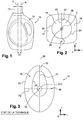
- a neck 12 of the container in the "home personal care” field, it is very common for a neck 12 of the container to be eccentric with respect to the center of the horizontal section of the container 10. Subsequently, such a container will be called “eccentric neck container”.
- eccentric neck container We represented at the figure 1 the main “C” axis of the container which passes through the center of the neck 12.
- A axis passing generally through the center of each section horizontal of the container.
- the eccentricity of the neck 12 results in a transverse offset "D1" of the main axis "C” of the container with respect to the axis "A", in the direction of the length of the oblong section of the container.
- the molding units are therefore designed to allow the production of large oblong containers.
- the molding units are made on the model of the molding units used to produce containers with a centered neck, as is for example shown in Fig. figure 2 .
- the molding unit has two mold supports 16 which are mounted articulated with respect to each other along a vertical hinge axis "B".
- a half-mold 18 is received in each support 16.
- the half-molds 18 each comprise a half-cavity which is reconstituted when the two half-molds 18 are joined, in the closed position of the mold supports 16.
- the cavity opens upwards through a passage orifice 20 which is intended to allow the neck 12 of the container to pass.
- the two half-molds 18 being identical by symmetry with respect to a parting line, only the half-mold 18 on the left will be described, the description being applicable to the half-mold 18 on the right by symmetry.
- the half-mold 18 is delimited longitudinally towards the front by a face 22 of the vertical transverse planar front seal which is provided with a mold cavity half (not shown).
- the two half-molds 18 are intended to be joined by pressing their respective joint faces 22 longitudinally against each other to reconstitute the mold cavity, as shown in figure 2 .
- the half-mold 18 is also delimited longitudinally towards the rear by an opposite vertical assembly face 24.
- the assembly face 24 has, in horizontal section, a convexly curved shape.
- the assembly face 24 is intended to be housed in a complementary receiving face of an associated mold support 16.
- the assembly face 24 generally has a semi-cylindrical shape. Thus, when the two half-molds 18 occupy their joined position, their assembly faces 24 have, in horizontal section, a circular shape.
- the orifice 20 for the passage is always arranged astride the parting line between the two half-molds 18. It is common practice for the orifice 20 for the passage of the neck to be centered relative to the circular section of the faces 24. assembly of the half-molds.
- the mold has two one-piece half-molds 18 which are each carried by an associated mold support (not shown).
- the two half-molds 18 being identical by symmetry with respect to a joint plane 26, we will only describe the half-mold 18 of left, the description being applicable to the right half-mold 18 by symmetry.
- the half-mold 18 is delimited longitudinally towards the front by a face 22 of the vertical transverse planar front seal which is provided with one half of the molding cavity 28.
- the seal face 22 extends in the seal plane 26.
- the two half-molds 18 are intended to be joined by pressing their respective joint faces 22 longitudinally against one another in order to reconstitute the mold cavity 28.
- the half-mold 18 is also delimited longitudinally towards the rear by an opposite vertical assembly face 24.
- the assembly face 24 has, in horizontal section, a convexly curved shape.
- the assembly face 24 is intended to be housed in a complementary receiving face of an associated mold support (not shown).
- the assembly face 24 generally has a cylindrical shape formed by the translation of a vertical generating line on the directing curve, formed by the curved shape of the assembly face 24 in horizontal section shown in figure 3 .
- the assembly face 24 has, in horizontal section, the shape of a half-oval. In the joined position, the assembly faces 24 of the two half-molds 18 therefore form a complete oval.
- the assembly face 24 of the mold in the joint position has a first plane "P1" which extends in the joint plane 26.
- the first plane "P1" forms a plane of symmetry for the assembly faces 24.
- the assembly face 24 of the mold in the joined position also has a second vertical plane "P2" of symmetry which extends orthogonally to the first plane “P1” of symmetry.
- the axis "C" of the passage orifice 20 here coincides with the central axis "O" of the mold 18.
- the cavity 28 extends more on one side of the mold 18 than on the other, here transversely towards the top of the figure 3 .
- Such a mold produced according to the state of the art advantageously makes it possible to produce large oblong containers while reducing the longitudinal bulk of the molds compared to molds having, in section, a circular outline, as illustrated in figure 2 .
- a longitudinal transverse plane will be designated as being a "horizontal" plane.
- thermoplastic material in particular of polyethylene terephthalate (PET) or of polypropylene (PP), with an axis of vertical orientation by blowing a preform (not shown).
- PET polyethylene terephthalate
- PP polypropylene
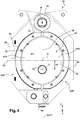
- the molding unit 30 has two mold supports 32A, 32B which are movably mounted between a closed position, shown in figure 4 , and an open position, shown in figure 5 .
- the two mold supports 32A, 32B are mounted to pivot with respect to each other about a vertical axis "B" of hinge 34 arranged along an end edge transverse of the mold supports 32A, 32B.
- Such an arrangement is generally called a "wallet mold”.
- the invention is particularly advantageous with a wallet mold, it is also applicable to mold supports movable in translation with respect to one another.
- Each mold support 32A, 32B is delimited longitudinally by a vertical front receiving face 36 and by a vertical rear face 38.
- the receiving face 36 of each mold support 32A, 32B is turned towards the other mold support 32A, 32B when they occupy their closed position.
- the molding unit 30 also comprises a mold 40 which has a molding cavity 48 having the shape of the container to be obtained by blow molding.
- the cavity 48 opens vertically upwards into a flat upper horizontal face 41 of the mold 40 through a passage orifice 42 intended to allow the neck 12 of the container to be obtained to pass.
- the passage orifice 42 has a central vertical "C" axis.
- the mold 40 comprises at least one pair of complementary half-molds 44A, 44B. As is particularly visible at the figure 6 , each half-mold 44A, 44B has a transverse vertical front seal face 46 in which one half of the mold cavity 48 is formed. When the two half-molds 44A, 44B occupy a joint position, as shown in figure 4 , the two half-molds 44A, 44B are pressed against each other by their respective seal face 46 so that their cavity halves reconstitute the mold cavity 48. The seal faces 46 then extend in a plane 50 of transverse vertical seal.
- the passage orifice 42 is arranged astride the joint plane 50, more particularly so that the central axis "C" of the passage orifice 42 is included in the joint plane 50.
- the mold 40 further comprises a base 44C separate from the half-molds 44A, 44B.
- each half-mold 44A, 44B is suitable for forming the body of the container, while the bottom 44C is suitable for forming the bottom of the container.
- the mold comprises only two half-molds.
- the imprint of each half-mold is then suitable for forming the body and the bottom of the container.
- each half-mold 44A, 44B also has a vertical rear assembly face 52 opposite to the seal face 46.
- the assembly face 52 here has the shape of a cylinder sector less than 180 ° so that the assembly faces 52 of the two joint half-molds 44A, 44B has, in horizontal section, an oblong shape, here in almond shape, elongated in a transverse direction.
- the assembly face 52 of each half-mold has the shape of an arc of a circle centered on a vertical reference axis (not shown) offset longitudinally towards the other half-mold 44B, 44A.
- the assembly faces of the two half-molds have, in horizontal section, an elliptical shape or an oval shape, elongated in a transverse direction.
- Each half-mold 44A, 44B is mounted in an associated mold support 32A, 32B by positioning its assembly face 52 against the associated receiving face 36 of the mold support 32A, 32B as shown in FIG. figure 4 .
- the receiving face 36 has a shape complementary to that of the assembly face 52 of the associated half-mold 44A, 44B.
- Each half-mold 44A, 44B is assembled with its associated mold support 32A, 32B by any assembly means already known in the field of molding units with interchangeable mold cavity 48.
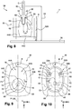
- the two half-molds 44A, 44B are able to occupy their position joined by their joint face 46 when the supports 32A, 32B occupy their closed position, as shown in figure 4 , and a disjointed position in which the faces 46 of the joint are moved apart when the supports 32A, 32B occupy their open position, as shown in figure 5 .
- the assembly faces 52 of the two half-molds 44A, 44B have a first plane "P1" which extends along the faces 46 of the joints.
- the first plane “P1” thus corresponds to the joint plane 50.
- the first plane “P1” passes through the center “C” of the passage orifice 42.
- the first plane “P1” also passes here through the hinge axis "B".
- the first plane “P1" of symmetry corresponds here to a transverse vertical plane of symmetry.
- the assembly faces 52 of the two half-molds 44A, 44B have a second plane "P2" of vertical symmetry orthogonal to the first plane “P1” of symmetry.
- the two planes "P1" and “P2" of symmetry intersect at a central vertical axis "O" of the mold 40.
- central "O" axis of the mold 40 does not necessarily coincide with the central "A" axis of the container to be formed.
- FIG. 7 We represented at the figure 7 an installation 54 for forming a thermoplastic container by forming, and in particular by blow molding or stretch blow molding, comprising a horizontal main wheel 56 mounted to rotate about a vertical central rotation axis "Y".
- the main wheel 56 comprises, at its periphery, a plurality of molding units 30, here ten in number, each made as has been described above.
- Each molding unit 30 is arranged so that the joint plane 50 of its half-molds 44A, 44B, in the closed position of the mold supports 32A, 32B, passes through the axis "Y" of rotation of the wheel. 56 main.
- the hinge 34 is turned towards the "Y" axis of rotation of so that the molds 44A, 44B open radially outwards from the main wheel 56.
- each molding unit 30 is carried by the main wheel 56 so that its hinge axis "B" is fixed relative to said main wheel 56.
- each molding unit 30 is associated with a blowing device 58 which is carried by the main wheel 56.
- the blowing device 58 comprises a blowing pipe 60 which is connected to a controlled source of pressurized forming fluid (not shown) and which opens into a connection end with the passage orifice 42 which is centered on the axis. "C" of the passage orifice 42.
- the connection end piece is here a lower bell 62 which is centered on the axis "C" of the orifice 42 for passage of the mold 40 of the associated molding unit 30 when the mold 40 occupies its joined position.
- the bell 62 is mounted to slide vertically along the axis "C" on a support 64 mounted on the main wheel 56 between an active lower position in which the lower edges of the bell 62 are pressed against the upper face 41 of the mold 40 in a joined position to surround the passage orifice 42, and an upper retracted position in which the bell 62 is spaced from the upper face 41 to allow the opening and closing of the mold supports 32A, 32B.
- the active position of the bell 62 is for example shown in figure 8 .
- the sliding axis "C" of the bell 62 is fixed relative to the main wheel 56.
- the bell 62 In its active position, the bell 62 is capable of filling a hot preform 63 with pressurized forming fluid through its neck 12 in order to press the walls thereof against the cavity 48 to form the body of the container.
- the central "C" axis of the passage orifice 42 is transversely offset by a distance “D2" with respect to the central "O" axis of the mold 40.
- the passage orifice 42 is offset by a distance “D” in a direction opposite to that of the hinge axis "B” so that the central axis "O” of the mold is interposed between the axis Central “C” of the orifice 42 of passage and the axis "B” of hinge.
- the offset of the axis "C" of the passage orifice 42 in the direction of the peripheral edge of the main wheel 56 advantageously allows better use of the volume between the mold supports 32A, 32B during the manufacture of sectional containers. oblong. This makes it possible in particular to reduce the bulk, in particular transverse, of the mold supports 32A, 32B relative to a molding unit of the state of the art in which the passage orifice is centered relative to the mold.
- the mold 40 is advantageously equipped with two boxing pistons 66 which are each mounted to slide in a working chamber 67 produced in a half-mold 44A, 44B associated between a position retracted relative to the mold cavity 48 and an extended position in the mold cavity 48.
- the boxing pistons 66 are for example actuated by means of the controlled source of pressurized forming fluid.
- the boxing pistons 66 are arranged in the thickness of each half-mold 44A, 44B near the axis "B" of the hinge.
- the boxing pistons 66 are more particularly visible in the example shown in figure 10 in which the molding cavity 48 has been shown in broken lines.
- the boxing pistons 66 are more particularly mounted generally facing each other, in a substantially longitudinal sliding direction.
- the boxing pistons 66 are then controlled from their retracted position to their position extended to depress the wall of the container against the pressure of the forming fluid to form the handle 14.
- the boxing pistons 66 are held extended until the wall of the container body has acquired its final shape.
- the offset of the orifice 42 for the passage of the neck 12 towards the peripheral edge of the main wheel 56 advantageously makes it possible to offset a part of the cavity 48 transversely towards the peripheral edge of the main wheel 56 relative to a mold with a passage hole. center.
- This very advantageously makes it possible to free up the space necessary for arranging boxing pistons 66 making it possible to obtain a thrust force sufficient to greatly exceed the pressure of the forming fluid contained in the container during its forming.
- the arrangement of such boxing pistons 66 in a molding unit 30 produced according to the teachings of the invention makes it possible in particular to obtain a mold 40 provided with boxing pistons 66 while keeping a small footprint, in particular transverse, reduced.
- Such a configuration thus allows this molding unit to be installed on a standard carousel as a replacement for a mold with a centered passage orifice.
- a mold comprising boxing pistons should be installed on a carousel of larger diameter than a standard carousel.
- Each half-mold 44A, 44B is here made in one piece.
- each half-mold 44A, 44B is made in two distinct parts formed by a shell 68 and by a shell holder 70.
- the internal shell 68 is delimited longitudinally by a front transverse vertical face forming the seal face 46 of the half-mold 44A and by a rear face, opposite to the face 46 of seal, forming a mounting face 72.
- the mounting face 72 has a convex shape.
- the outer shell holder 70 is delimited longitudinally by a front receiving face 74 of a shape complementary to that of the mounting face 72.
- the shell 68 is intended to be housed in the shell holder 70, its mounting face 72 being pressed against the receiving face 74 of the shell holder 70.
- the shell holder 70 is also delimited towards the rear by a rear face opposite which forms the assembly face 52 of the half-mold 44A.
- the shell 68 carries the mold cavity half 48.
- the shell holder 70 is equipped with means (not shown) for cooling the shell 68.
- the mounting face 72 has, in horizontal section, the shape of a semicircle which is centered on the central axis "C" of the passage orifice 42. This is for example the case of a mold 40 used to produce containers having a centered neck 12.
- the shell 68 is arranged transversely eccentric with respect to the assembly face 52 in the shell holder 70 as shown on figure 9 .
- the receiving face 74 of the shell holder 70 is offset transversely away from the hinge axis "B” with respect to the second plane "P2" of symmetry of the assembly face 52 of the mold 40.
- the mounting face 72 is arranged concentrically with the assembly face 52 of the mold 40.
- the molding unit 30 produced according to any one of the embodiments described above allows advantageously to produce the containers with an eccentric neck while offering a reduced size compared to the molding units of the state of the art.
- the molding units produced according to the teachings of the invention also make it possible easily to produce molds equipped with boxing pistons without it being necessary to increase the size of the molding unit.
- the molding units produced according to the teachings of the invention also make it possible to easily produce containers with a centered neck by replacing the molds or simply the shell when each half-mold is made in two parts.
Landscapes
- Engineering & Computer Science (AREA)
- Manufacturing & Machinery (AREA)
- Mechanical Engineering (AREA)
- Moulds For Moulding Plastics Or The Like (AREA)
- Blow-Moulding Or Thermoforming Of Plastics Or The Like (AREA)
Claims (11)
- Formeinheit (30) zum Formen von Behältern aus thermoplastischem Material aus Vorformlingen (63), insbesondere durch Blasen oder Streckblasen, wobei die Formeinheit (30) Folgendes aufweist:- zwei Formträger (32A, 32B), die zwischen einer offenen Position und einer geschlossenen Position beweglich sind;- wobei eine Form (40) mindestens zwei Halbformen (44A, 44B) aufweist, die jeweils dazu bestimmt sind, auf einem der zugehörigen Formträger (32A, 32B) angebracht zu sein, wobei jede Halbform (44A, 44B) von einer vorderen Fügefläche (46) und einer hinteren Verbindungsfläche (52) begrenzt ist, wobei die zwei Halbformen (44A, 44B) über ihre Fügefläche (46) eine zusammengefügte Position einnehmen können, wenn die Formträger (32A, 32B) ihre geschlossene Position einnehmen;- eine Formungshöhlung (48), die in zwei Abschnitten in jeder Fügefläche (46) ausgebildet ist und die wiederhergestellt wird, wenn die Form (40) ihre zusammengefügte Position einnimmt, wobei die Höhlung (48) vertikal nach oben in eine Durchlassöffnung (42) mündet, die dazu bestimmt ist, einen Hals (12) des Vorformlings (63) hindurchzulassen;wobei die Verbindungsflächen (52) der Form (40) in der zusammengefügten Position Folgendes aufweisen:- eine erste vertikale Querebene (P1), die sich entlang der Fügeflächen (46) erstreckt und durch den Mittelpunkt (C) der Durchlassöffnung (42) verläuft, und- eine zweite vertikale Symmetrieebene (P2), die orthogonal zur ersten Symmetrieebene (P1) verläuft, wobei sich die zwei Symmetrieebenen (P1, P2) an einer vertikalen Mittelachse (O) der Form (40) kreuzen; dadurch gekennzeichnet, dass die Mittelachse (C) der Durchlassöffnung (42) in Querrichtung bezogen auf die Mittelachse (O) der Form (40) versetzt ist.
- Formeinheit (30) nach dem vorhergehenden Anspruch, dadurch gekennzeichnet, dass die erste Ebene (P1) durch eine Scharnierachse (B) zwischen den zwei Formträgern verläuft, wobei die Durchlassöffnung (42) in einer Richtung versetzt ist, die jener der Scharnierachse (B) entgegengesetzt ist, so dass die Mittelachse (O) der Form (40) zwischen der Mittelachse (C) der Durchlassöffnung (42) und der Scharnierachse (B) liegt.
- Formeinheit (30) nach einem der vorhergehenden Ansprüche, dadurch gekennzeichnet, dass die Verbindungsflächen (52) in der zusammengefügten Position der Form (40) einen elliptischen horizontalen Querschnitt aufweisen.
- Formeinheit (30) nach einem der Ansprüche 1 oder 2, dadurch gekennzeichnet, dass die Verbindungsfläche (52) jeder Halbform (44A, 44B) in der zusammengefügten Position der Form einen kreisbogenförmigen horizontalen Querschnitt aufweist, der sich über einen Abschnitt kleiner als 180° erstreckt.
- Formeinheit (30) nach einem der vorhergehenden Ansprüche, dadurch gekennzeichnet, dass jede Halbform (44A, 44B) einstückig ausgebildet ist.
- Formeinheit (30) nach einem der Ansprüche 1 bis 4, dadurch gekennzeichnet, dass jede Halbform (44A, 44B) aus zwei Abschnitten gebildet ist:- einer Innenschale (68), die in Längsrichtung von einer vorderen Fläche, die die Fügefläche (46) der Halbform (44A, 44B) bildet, und von einer hinteren Fläche, die der Fügefläche (46) gegenüberliegt und eine konvex geformte Montagefläche (72) bildet, begrenzt wird;- einem äußeren Schalenträger (70), der in Längsrichtung von einer vorderen Aufnahmefläche (74) mit einer Form, die zu jener der Montagefläche (72) der Schale (68) komplementär ist, und in der die Montagefläche (72) der Schale (68) aufgenommen ist, und von einer gegenüberliegenden hinteren Fläche, die die Verbindungsfläche (52) der Halbform (44A, 44B) bildet, begrenzt ist.
- Formeinheit (30) nach dem vorhergehenden Anspruch, dadurch gekennzeichnet, dass die Montagefläche (72) der Schale im horizontalen Schnitt eine Kreisbogenform aufweist.
- Formeinheit (30) nach dem vorhergehenden Anspruch, dadurch gekennzeichnet, dass jede Montagefläche (72) im horizontalen Schnitt eine Halbkreisform aufweist, die auf der Mittelachse (C) der Durchlassöffnung (42) zentriert ist.
- Formeinheit (30) nach Anspruch 6 oder 7, dadurch gekennzeichnet, dass die Montagefläche (72) zur Verbindungsfläche (52) der zugehörigen Halbform (44A, 44B) konzentrisch ist.
- Formeinheit (30) nach einem der vorhergehenden Ansprüche, dadurch gekennzeichnet, dass sie zwei Boxing-Kolben (66) aufweist, die jeweils in einer zugehörigen Halbform (44A, 44B) zwischen einer eingefahrenen Position bezogen auf die Formungshöhlung (48) und einer ausgefahrenen Position in der Formungshöhlung (48) gleitend gelagert sind, wobei die Boxing-Kolben (66) in der Dicke jeder Halbform (44A, 44B) in der Nähe der Scharnierachse (B) angeordnet sind.
- Formungsanlage (54), dadurch gekennzeichnet, dass sie Folgendes aufweist:- ein Hauptdrehrad (56);- eine Mehrzahl von Formungseinheiten (30) nach einem der vorhergehenden Ansprüche, wobei die Formungseinheiten (30) regelmäßig am Rand des Hauptrads (56) verteilt sind;- Formungsvorrichtungen (58) aufweisend ein Ansatzstück zur Verbindung mit der Durchlassöffnung (42), das auf der Achse (C) der Durchlassöffnung (42) zentriert ist.
Applications Claiming Priority (1)
| Application Number | Priority Date | Filing Date | Title |
|---|---|---|---|
| FR1853297A FR3080055A1 (fr) | 2018-04-16 | 2018-04-16 | Unite de moulage avec orifice de passage de col decentre |
Publications (2)
| Publication Number | Publication Date |
|---|---|
| EP3556535A1 EP3556535A1 (de) | 2019-10-23 |
| EP3556535B1 true EP3556535B1 (de) | 2021-02-17 |
Family
ID=63490542
Family Applications (1)
| Application Number | Title | Priority Date | Filing Date |
|---|---|---|---|
| EP19168247.5A Active EP3556535B1 (de) | 2018-04-16 | 2019-04-09 | Spritzgusseinheit mit durchlassöffnung eines dezentrierten stutzens |
Country Status (5)
| Country | Link |
|---|---|
| US (1) | US10987849B2 (de) |
| EP (1) | EP3556535B1 (de) |
| CN (1) | CN110385847A (de) |
| FR (1) | FR3080055A1 (de) |
| MX (1) | MX2019003986A (de) |
Families Citing this family (1)
| Publication number | Priority date | Publication date | Assignee | Title |
|---|---|---|---|---|
| CN114769595A (zh) * | 2022-04-14 | 2022-07-22 | 漳州市合琦靶材科技有限公司 | 一种铝铬合金靶材的制备工艺及其应用 |
Family Cites Families (18)
| Publication number | Priority date | Publication date | Assignee | Title |
|---|---|---|---|---|
| US3408692A (en) * | 1965-05-21 | 1968-11-05 | Owens Illinois Inc | Apparatus for producing offset finish on containers |
| US3781395A (en) * | 1971-01-28 | 1973-12-25 | Owens Illinois Inc | Method for blow molding plastic articles |
| US3944642A (en) * | 1971-05-17 | 1976-03-16 | Owens-Illinois, Inc. | Method for blow molding plastic articles |
| US4195053A (en) * | 1978-10-26 | 1980-03-25 | Hoover Universal, Inc. | Method and apparatus for blow molding containers |
| JPS5759725A (en) * | 1980-09-29 | 1982-04-10 | Toyo Seikan Kaisha Ltd | Polyester container with handle and preparation thereof |
| US5178817A (en) * | 1988-09-06 | 1993-01-12 | Dai Nippon Insatsu K. K. | Stretch blow molding method for manufacturing an expanded bottle |
| EP1278626B1 (de) * | 1999-08-02 | 2005-08-24 | Tjandra Limanjaya | Verfahren und vorrichtung zur herstellung einer pet flasche mit aussermittigem flaschenhals |
| ITPN20010009A1 (it) * | 2001-02-07 | 2002-08-07 | Sipa Spa | Procedimento per la produzione di contenitori in pet con bocca fuoricentro |
| US7150371B1 (en) * | 2003-10-02 | 2006-12-19 | Plastipak Packaging, Inc. | Extrusion blow molded container, apparatus and method |
| KR100650155B1 (ko) * | 2003-12-19 | 2006-11-27 | 조자연 | 사출 중공성형법에 의한 손잡이부가 형성된 pet 병의제조방법 및 이에 의해 제조된 pet 병 |
| FR2883794B1 (fr) * | 2005-04-04 | 2007-06-15 | Sidel Sas | Dispositif de moulage ajustable en hauteur pour le moulage de recipients thermoplastiques de hauteurs diverses |
| US20070023385A1 (en) * | 2005-08-01 | 2007-02-01 | Janeczek James D | Container and blow mold assembly |
| FR2889820B1 (fr) * | 2005-08-18 | 2009-10-30 | Sidel Sas | Moule de soufflage pour recipients thermoplastiques munis d'une poignee integrale, installation equipee de tels moules, et recipient fabrique avec un tel moule |
| FR2930189B1 (fr) * | 2008-04-21 | 2013-02-01 | Sidel Participations | Dispositif de moulage de recipients comprenant des moyens de reglage des dimensions volumiques de la cavite de moulage |
| FR2949704B1 (fr) * | 2009-09-07 | 2011-11-25 | Sidel Participations | Procede de changement des empreintes de moulage d'une station de soufflage de recipients en plastique |
| FR2972385B1 (fr) * | 2011-03-08 | 2013-04-26 | Sidel Participations | Systeme automatise pour le changement de moule d'une unite de moulage equipant une machine de fabrication de recipients |
| US9505163B2 (en) * | 2014-01-21 | 2016-11-29 | Dt Inventions, Llc | Manufacturing method and device for a container with an integral handle |
| FR3066136B1 (fr) * | 2017-12-22 | 2019-08-09 | Sidel Participations | Demi moule presentant une face d'assemblage cylindrique et procede de realisation |
-
2018
- 2018-04-16 FR FR1853297A patent/FR3080055A1/fr not_active Ceased
-
2019
- 2019-04-05 MX MX2019003986A patent/MX2019003986A/es unknown
- 2019-04-09 EP EP19168247.5A patent/EP3556535B1/de active Active
- 2019-04-16 CN CN201910301497.3A patent/CN110385847A/zh active Pending
- 2019-04-16 US US16/385,199 patent/US10987849B2/en active Active
Non-Patent Citations (1)
| Title |
|---|
| None * |
Also Published As
| Publication number | Publication date |
|---|---|
| EP3556535A1 (de) | 2019-10-23 |
| CN110385847A (zh) | 2019-10-29 |
| US20190315041A1 (en) | 2019-10-17 |
| FR3080055A1 (fr) | 2019-10-18 |
| US10987849B2 (en) | 2021-04-27 |
| MX2019003986A (es) | 2019-11-28 |
Similar Documents
| Publication | Publication Date | Title |
|---|---|---|
| EP1216136B1 (de) | Blasformmaschine mit einem schliess- und verriegelungsmechanismus | |
| FR2659265A1 (fr) | Procede de dispositif pour fabriquer des recipients en matieres thermoplastiques par soufflage ou etirage-soufflage. | |
| WO2012104499A2 (fr) | Récipient modulaire composé d'une pluralité de conteneurs emboîtables axialement, et procédé d'obtention de tels conteneurs par soufflage d'une préforme. | |
| FR2490188A1 (fr) | Recipient en matiere plastique muni d'une jupe pour fixer une etiquette | |
| FR1450764A (fr) | Perfectionnements aux bouteilles en matière plastique | |
| FR2639578A1 (fr) | Bidon a trois poignees en matiere plastique soufflee ainsi que dispositif et procede de fabrication de ce bidon | |
| EP3556535B1 (de) | Spritzgusseinheit mit durchlassöffnung eines dezentrierten stutzens | |
| EP2125331B1 (de) | Formvorrichtung zur herstellung von gefässen aus einem thermoplastischen material | |
| EP1901908B1 (de) | Formeinheiten und formmaschine mit veränderlichem abstand | |
| EP2111967B1 (de) | Vorrichtung zum Formgießen von Behältern einschließlich Mittel zum Regulieren der Volumenmaße des zu formenden Hohlraums | |
| EP3131734B1 (de) | Giesseinheit mit formbodenbetätigungseinrichtung auf einer fixen halterung | |
| EP3727795B1 (de) | Halbform mit zylindrischer montagefläche und herstellungsverfahren | |
| FR3047234A1 (fr) | Flacon pressurise en matiere plastique | |
| EP2626190B1 (de) | Vorrichtungen zur herstellung von behältern | |
| EP2978584A1 (de) | Behälter mit verstärktem boden und verfahren zur herstellung solch eines behälters | |
| EP1405710A1 (de) | Weithalsvorformling mit Schutz gegen mechanische Schäden des Innenabdichtungsbereichs | |
| FR3006683A1 (fr) | Procede de fabrication d'un recipient en verre. | |
| FR2964060A1 (fr) | Moule rotatif multi-etage pour injection-soufflage et multi-injection | |
| FR3059306B1 (fr) | Pots a contre-depouille, moules ouvrants, machines de formages et lignes de fabrication de pots a contre-depouille | |
| FR3152425A1 (fr) | Préforme injectée adaptée pour être transférée dans un moule de soufflage, procédé de fabrication d’un flacon par soufflage de préforme et ensemble comprenant un flacon soufflé et un organe d’obturation | |
| FR2821583A1 (fr) | Procede de fabrication par la technique du soufflage d'un recipient en matiere plastique et plus particulierement d'un flacon destine notamment au domaine de la cosmetique | |
| EP2011627A1 (de) | Form für die Herstellung von Behältern mit Griff | |
| FR2766119A1 (fr) | Procede de fabrication d'un tube en matiere plastique et tube obtenu par ce procede | |
| EP1391388B1 (de) | Behälter mit verstärkter Wand | |
| FR2922145A3 (fr) | Procede de fabrication d'une poche tubulaire et poche ainsi obtenue. |
Legal Events
| Date | Code | Title | Description |
|---|---|---|---|
| PUAI | Public reference made under article 153(3) epc to a published international application that has entered the european phase |
Free format text: ORIGINAL CODE: 0009012 |
|
| STAA | Information on the status of an ep patent application or granted ep patent |
Free format text: STATUS: THE APPLICATION HAS BEEN PUBLISHED |
|
| AK | Designated contracting states |
Kind code of ref document: A1 Designated state(s): AL AT BE BG CH CY CZ DE DK EE ES FI FR GB GR HR HU IE IS IT LI LT LU LV MC MK MT NL NO PL PT RO RS SE SI SK SM TR |
|
| AX | Request for extension of the european patent |
Extension state: BA ME |
|
| STAA | Information on the status of an ep patent application or granted ep patent |
Free format text: STATUS: REQUEST FOR EXAMINATION WAS MADE |
|
| 17P | Request for examination filed |
Effective date: 20200422 |
|
| RBV | Designated contracting states (corrected) |
Designated state(s): AL AT BE BG CH CY CZ DE DK EE ES FI FR GB GR HR HU IE IS IT LI LT LU LV MC MK MT NL NO PL PT RO RS SE SI SK SM TR |
|
| GRAP | Despatch of communication of intention to grant a patent |
Free format text: ORIGINAL CODE: EPIDOSNIGR1 |
|
| STAA | Information on the status of an ep patent application or granted ep patent |
Free format text: STATUS: GRANT OF PATENT IS INTENDED |
|
| RIC1 | Information provided on ipc code assigned before grant |
Ipc: B29C 49/48 20060101AFI20200812BHEP Ipc: B29L 31/00 20060101ALN20200812BHEP Ipc: B29K 67/00 20060101ALN20200812BHEP Ipc: B29C 49/06 20060101ALN20200812BHEP Ipc: B29C 49/36 20060101ALN20200812BHEP |
|
| INTG | Intention to grant announced |
Effective date: 20200901 |
|
| GRAS | Grant fee paid |
Free format text: ORIGINAL CODE: EPIDOSNIGR3 |
|
| GRAA | (expected) grant |
Free format text: ORIGINAL CODE: 0009210 |
|
| STAA | Information on the status of an ep patent application or granted ep patent |
Free format text: STATUS: THE PATENT HAS BEEN GRANTED |
|
| AK | Designated contracting states |
Kind code of ref document: B1 Designated state(s): AL AT BE BG CH CY CZ DE DK EE ES FI FR GB GR HR HU IE IS IT LI LT LU LV MC MK MT NL NO PL PT RO RS SE SI SK SM TR |
|
| REG | Reference to a national code |
Ref country code: GB Ref legal event code: FG4D Free format text: NOT ENGLISH |
|
| REG | Reference to a national code |
Ref country code: CH Ref legal event code: EP |
|
| REG | Reference to a national code |
Ref country code: DE Ref legal event code: R096 Ref document number: 602019002487 Country of ref document: DE |
|
| REG | Reference to a national code |
Ref country code: AT Ref legal event code: REF Ref document number: 1360912 Country of ref document: AT Kind code of ref document: T Effective date: 20210315 |
|
| REG | Reference to a national code |
Ref country code: IE Ref legal event code: FG4D Free format text: LANGUAGE OF EP DOCUMENT: FRENCH |
|
| REG | Reference to a national code |
Ref country code: LT Ref legal event code: MG9D |
|
| REG | Reference to a national code |
Ref country code: NL Ref legal event code: MP Effective date: 20210217 |
|
| PG25 | Lapsed in a contracting state [announced via postgrant information from national office to epo] |
Ref country code: PT Free format text: LAPSE BECAUSE OF FAILURE TO SUBMIT A TRANSLATION OF THE DESCRIPTION OR TO PAY THE FEE WITHIN THE PRESCRIBED TIME-LIMIT Effective date: 20210617 Ref country code: NO Free format text: LAPSE BECAUSE OF FAILURE TO SUBMIT A TRANSLATION OF THE DESCRIPTION OR TO PAY THE FEE WITHIN THE PRESCRIBED TIME-LIMIT Effective date: 20210517 Ref country code: LT Free format text: LAPSE BECAUSE OF FAILURE TO SUBMIT A TRANSLATION OF THE DESCRIPTION OR TO PAY THE FEE WITHIN THE PRESCRIBED TIME-LIMIT Effective date: 20210217 Ref country code: FI Free format text: LAPSE BECAUSE OF FAILURE TO SUBMIT A TRANSLATION OF THE DESCRIPTION OR TO PAY THE FEE WITHIN THE PRESCRIBED TIME-LIMIT Effective date: 20210217 Ref country code: GR Free format text: LAPSE BECAUSE OF FAILURE TO SUBMIT A TRANSLATION OF THE DESCRIPTION OR TO PAY THE FEE WITHIN THE PRESCRIBED TIME-LIMIT Effective date: 20210518 Ref country code: HR Free format text: LAPSE BECAUSE OF FAILURE TO SUBMIT A TRANSLATION OF THE DESCRIPTION OR TO PAY THE FEE WITHIN THE PRESCRIBED TIME-LIMIT Effective date: 20210217 Ref country code: BG Free format text: LAPSE BECAUSE OF FAILURE TO SUBMIT A TRANSLATION OF THE DESCRIPTION OR TO PAY THE FEE WITHIN THE PRESCRIBED TIME-LIMIT Effective date: 20210517 |
|
| REG | Reference to a national code |
Ref country code: AT Ref legal event code: MK05 Ref document number: 1360912 Country of ref document: AT Kind code of ref document: T Effective date: 20210217 |
|
| PG25 | Lapsed in a contracting state [announced via postgrant information from national office to epo] |
Ref country code: LV Free format text: LAPSE BECAUSE OF FAILURE TO SUBMIT A TRANSLATION OF THE DESCRIPTION OR TO PAY THE FEE WITHIN THE PRESCRIBED TIME-LIMIT Effective date: 20210217 Ref country code: PL Free format text: LAPSE BECAUSE OF FAILURE TO SUBMIT A TRANSLATION OF THE DESCRIPTION OR TO PAY THE FEE WITHIN THE PRESCRIBED TIME-LIMIT Effective date: 20210217 Ref country code: NL Free format text: LAPSE BECAUSE OF FAILURE TO SUBMIT A TRANSLATION OF THE DESCRIPTION OR TO PAY THE FEE WITHIN THE PRESCRIBED TIME-LIMIT Effective date: 20210217 Ref country code: RS Free format text: LAPSE BECAUSE OF FAILURE TO SUBMIT A TRANSLATION OF THE DESCRIPTION OR TO PAY THE FEE WITHIN THE PRESCRIBED TIME-LIMIT Effective date: 20210217 Ref country code: SE Free format text: LAPSE BECAUSE OF FAILURE TO SUBMIT A TRANSLATION OF THE DESCRIPTION OR TO PAY THE FEE WITHIN THE PRESCRIBED TIME-LIMIT Effective date: 20210217 |
|
| PG25 | Lapsed in a contracting state [announced via postgrant information from national office to epo] |
Ref country code: IS Free format text: LAPSE BECAUSE OF FAILURE TO SUBMIT A TRANSLATION OF THE DESCRIPTION OR TO PAY THE FEE WITHIN THE PRESCRIBED TIME-LIMIT Effective date: 20210617 |
|
| PG25 | Lapsed in a contracting state [announced via postgrant information from national office to epo] |
Ref country code: AT Free format text: LAPSE BECAUSE OF FAILURE TO SUBMIT A TRANSLATION OF THE DESCRIPTION OR TO PAY THE FEE WITHIN THE PRESCRIBED TIME-LIMIT Effective date: 20210217 Ref country code: SM Free format text: LAPSE BECAUSE OF FAILURE TO SUBMIT A TRANSLATION OF THE DESCRIPTION OR TO PAY THE FEE WITHIN THE PRESCRIBED TIME-LIMIT Effective date: 20210217 Ref country code: CZ Free format text: LAPSE BECAUSE OF FAILURE TO SUBMIT A TRANSLATION OF THE DESCRIPTION OR TO PAY THE FEE WITHIN THE PRESCRIBED TIME-LIMIT Effective date: 20210217 Ref country code: EE Free format text: LAPSE BECAUSE OF FAILURE TO SUBMIT A TRANSLATION OF THE DESCRIPTION OR TO PAY THE FEE WITHIN THE PRESCRIBED TIME-LIMIT Effective date: 20210217 |
|
| REG | Reference to a national code |
Ref country code: DE Ref legal event code: R097 Ref document number: 602019002487 Country of ref document: DE |
|
| PG25 | Lapsed in a contracting state [announced via postgrant information from national office to epo] |
Ref country code: MC Free format text: LAPSE BECAUSE OF FAILURE TO SUBMIT A TRANSLATION OF THE DESCRIPTION OR TO PAY THE FEE WITHIN THE PRESCRIBED TIME-LIMIT Effective date: 20210217 Ref country code: DK Free format text: LAPSE BECAUSE OF FAILURE TO SUBMIT A TRANSLATION OF THE DESCRIPTION OR TO PAY THE FEE WITHIN THE PRESCRIBED TIME-LIMIT Effective date: 20210217 Ref country code: RO Free format text: LAPSE BECAUSE OF FAILURE TO SUBMIT A TRANSLATION OF THE DESCRIPTION OR TO PAY THE FEE WITHIN THE PRESCRIBED TIME-LIMIT Effective date: 20210217 Ref country code: SK Free format text: LAPSE BECAUSE OF FAILURE TO SUBMIT A TRANSLATION OF THE DESCRIPTION OR TO PAY THE FEE WITHIN THE PRESCRIBED TIME-LIMIT Effective date: 20210217 |
|
| PLBE | No opposition filed within time limit |
Free format text: ORIGINAL CODE: 0009261 |
|
| STAA | Information on the status of an ep patent application or granted ep patent |
Free format text: STATUS: NO OPPOSITION FILED WITHIN TIME LIMIT |
|
| PG25 | Lapsed in a contracting state [announced via postgrant information from national office to epo] |
Ref country code: LU Free format text: LAPSE BECAUSE OF NON-PAYMENT OF DUE FEES Effective date: 20210409 |
|
| REG | Reference to a national code |
Ref country code: BE Ref legal event code: MM Effective date: 20210430 |
|
| 26N | No opposition filed |
Effective date: 20211118 |
|
| PG25 | Lapsed in a contracting state [announced via postgrant information from national office to epo] |
Ref country code: AL Free format text: LAPSE BECAUSE OF FAILURE TO SUBMIT A TRANSLATION OF THE DESCRIPTION OR TO PAY THE FEE WITHIN THE PRESCRIBED TIME-LIMIT Effective date: 20210217 Ref country code: ES Free format text: LAPSE BECAUSE OF FAILURE TO SUBMIT A TRANSLATION OF THE DESCRIPTION OR TO PAY THE FEE WITHIN THE PRESCRIBED TIME-LIMIT Effective date: 20210217 |
|
| PG25 | Lapsed in a contracting state [announced via postgrant information from national office to epo] |
Ref country code: SI Free format text: LAPSE BECAUSE OF FAILURE TO SUBMIT A TRANSLATION OF THE DESCRIPTION OR TO PAY THE FEE WITHIN THE PRESCRIBED TIME-LIMIT Effective date: 20210217 |
|
| PG25 | Lapsed in a contracting state [announced via postgrant information from national office to epo] |
Ref country code: IE Free format text: LAPSE BECAUSE OF NON-PAYMENT OF DUE FEES Effective date: 20210409 |
|
| PG25 | Lapsed in a contracting state [announced via postgrant information from national office to epo] |
Ref country code: IS Free format text: LAPSE BECAUSE OF FAILURE TO SUBMIT A TRANSLATION OF THE DESCRIPTION OR TO PAY THE FEE WITHIN THE PRESCRIBED TIME-LIMIT Effective date: 20210617 |
|
| PG25 | Lapsed in a contracting state [announced via postgrant information from national office to epo] |
Ref country code: BE Free format text: LAPSE BECAUSE OF NON-PAYMENT OF DUE FEES Effective date: 20210430 |
|
| REG | Reference to a national code |
Ref country code: CH Ref legal event code: PL |
|
| PG25 | Lapsed in a contracting state [announced via postgrant information from national office to epo] |
Ref country code: LI Free format text: LAPSE BECAUSE OF NON-PAYMENT OF DUE FEES Effective date: 20220430 Ref country code: CH Free format text: LAPSE BECAUSE OF NON-PAYMENT OF DUE FEES Effective date: 20220430 |
|
| P01 | Opt-out of the competence of the unified patent court (upc) registered |
Effective date: 20230403 |
|
| PG25 | Lapsed in a contracting state [announced via postgrant information from national office to epo] |
Ref country code: CY Free format text: LAPSE BECAUSE OF FAILURE TO SUBMIT A TRANSLATION OF THE DESCRIPTION OR TO PAY THE FEE WITHIN THE PRESCRIBED TIME-LIMIT Effective date: 20210217 |
|
| PG25 | Lapsed in a contracting state [announced via postgrant information from national office to epo] |
Ref country code: HU Free format text: LAPSE BECAUSE OF FAILURE TO SUBMIT A TRANSLATION OF THE DESCRIPTION OR TO PAY THE FEE WITHIN THE PRESCRIBED TIME-LIMIT; INVALID AB INITIO Effective date: 20190409 |
|
| GBPC | Gb: european patent ceased through non-payment of renewal fee |
Effective date: 20230409 |
|
| PG25 | Lapsed in a contracting state [announced via postgrant information from national office to epo] |
Ref country code: GB Free format text: LAPSE BECAUSE OF NON-PAYMENT OF DUE FEES Effective date: 20230409 |
|
| PG25 | Lapsed in a contracting state [announced via postgrant information from national office to epo] |
Ref country code: GB Free format text: LAPSE BECAUSE OF NON-PAYMENT OF DUE FEES Effective date: 20230409 |
|
| PG25 | Lapsed in a contracting state [announced via postgrant information from national office to epo] |
Ref country code: MK Free format text: LAPSE BECAUSE OF FAILURE TO SUBMIT A TRANSLATION OF THE DESCRIPTION OR TO PAY THE FEE WITHIN THE PRESCRIBED TIME-LIMIT Effective date: 20210217 |
|
| PG25 | Lapsed in a contracting state [announced via postgrant information from national office to epo] |
Ref country code: TR Free format text: LAPSE BECAUSE OF FAILURE TO SUBMIT A TRANSLATION OF THE DESCRIPTION OR TO PAY THE FEE WITHIN THE PRESCRIBED TIME-LIMIT Effective date: 20210217 |
|
| PG25 | Lapsed in a contracting state [announced via postgrant information from national office to epo] |
Ref country code: MT Free format text: LAPSE BECAUSE OF FAILURE TO SUBMIT A TRANSLATION OF THE DESCRIPTION OR TO PAY THE FEE WITHIN THE PRESCRIBED TIME-LIMIT Effective date: 20210217 |
|
| PGFP | Annual fee paid to national office [announced via postgrant information from national office to epo] |
Ref country code: DE Payment date: 20250319 Year of fee payment: 7 |
|
| PGFP | Annual fee paid to national office [announced via postgrant information from national office to epo] |
Ref country code: IT Payment date: 20260319 Year of fee payment: 8 |
|
| PGFP | Annual fee paid to national office [announced via postgrant information from national office to epo] |
Ref country code: FR Payment date: 20260319 Year of fee payment: 8 |