EP2125331B1 - Formvorrichtung zur herstellung von gefässen aus einem thermoplastischen material - Google Patents
Formvorrichtung zur herstellung von gefässen aus einem thermoplastischen material Download PDFInfo
- Publication number
- EP2125331B1 EP2125331B1 EP08762122.3A EP08762122A EP2125331B1 EP 2125331 B1 EP2125331 B1 EP 2125331B1 EP 08762122 A EP08762122 A EP 08762122A EP 2125331 B1 EP2125331 B1 EP 2125331B1
- Authority
- EP
- European Patent Office
- Prior art keywords
- moulds
- moulding device
- molds
- mobile assembly
- closed position
- Prior art date
- Legal status (The legal status is an assumption and is not a legal conclusion. Google has not performed a legal analysis and makes no representation as to the accuracy of the status listed.)
- Not-in-force
Links
- 238000000465 moulding Methods 0.000 title claims description 87
- 239000012815 thermoplastic material Substances 0.000 title description 5
- 238000000071 blow moulding Methods 0.000 claims description 11
- 230000000295 complement effect Effects 0.000 claims description 4
- 230000015572 biosynthetic process Effects 0.000 claims description 3
- 229920001169 thermoplastic Polymers 0.000 claims 1
- 239000004416 thermosoftening plastic Substances 0.000 claims 1
- 238000007664 blowing Methods 0.000 description 11
- 238000004519 manufacturing process Methods 0.000 description 4
- 238000006073 displacement reaction Methods 0.000 description 2
- 230000000712 assembly Effects 0.000 description 1
- 238000000429 assembly Methods 0.000 description 1
- 239000000470 constituent Substances 0.000 description 1
- 230000003292 diminished effect Effects 0.000 description 1
- 239000012530 fluid Substances 0.000 description 1
- 238000012423 maintenance Methods 0.000 description 1
- 239000000463 material Substances 0.000 description 1
- 238000007789 sealing Methods 0.000 description 1
- 230000001360 synchronised effect Effects 0.000 description 1
Images


Classifications
-
- B—PERFORMING OPERATIONS; TRANSPORTING
- B29—WORKING OF PLASTICS; WORKING OF SUBSTANCES IN A PLASTIC STATE IN GENERAL
- B29C—SHAPING OR JOINING OF PLASTICS; SHAPING OF MATERIAL IN A PLASTIC STATE, NOT OTHERWISE PROVIDED FOR; AFTER-TREATMENT OF THE SHAPED PRODUCTS, e.g. REPAIRING
- B29C49/00—Blow-moulding, i.e. blowing a preform or parison to a desired shape within a mould; Apparatus therefor
- B29C49/42—Component parts, details or accessories; Auxiliary operations
- B29C49/56—Opening, closing or clamping means
- B29C49/5601—Mechanically operated, i.e. closing or opening of the mould parts is done by mechanic means
- B29C49/5602—Mechanically operated, i.e. closing or opening of the mould parts is done by mechanic means using cams
-
- B—PERFORMING OPERATIONS; TRANSPORTING
- B29—WORKING OF PLASTICS; WORKING OF SUBSTANCES IN A PLASTIC STATE IN GENERAL
- B29C—SHAPING OR JOINING OF PLASTICS; SHAPING OF MATERIAL IN A PLASTIC STATE, NOT OTHERWISE PROVIDED FOR; AFTER-TREATMENT OF THE SHAPED PRODUCTS, e.g. REPAIRING
- B29C49/00—Blow-moulding, i.e. blowing a preform or parison to a desired shape within a mould; Apparatus therefor
- B29C49/42—Component parts, details or accessories; Auxiliary operations
- B29C49/48—Moulds
- B29C2049/4879—Moulds characterised by mould configurations
- B29C2049/4892—Mould halves consisting of an independent main and bottom part
-
- B—PERFORMING OPERATIONS; TRANSPORTING
- B29—WORKING OF PLASTICS; WORKING OF SUBSTANCES IN A PLASTIC STATE IN GENERAL
- B29C—SHAPING OR JOINING OF PLASTICS; SHAPING OF MATERIAL IN A PLASTIC STATE, NOT OTHERWISE PROVIDED FOR; AFTER-TREATMENT OF THE SHAPED PRODUCTS, e.g. REPAIRING
- B29C49/00—Blow-moulding, i.e. blowing a preform or parison to a desired shape within a mould; Apparatus therefor
- B29C49/42—Component parts, details or accessories; Auxiliary operations
- B29C49/56—Opening, closing or clamping means
- B29C2049/5636—Opening, closing or clamping means using closing means as clamping means
-
- B—PERFORMING OPERATIONS; TRANSPORTING
- B29—WORKING OF PLASTICS; WORKING OF SUBSTANCES IN A PLASTIC STATE IN GENERAL
- B29C—SHAPING OR JOINING OF PLASTICS; SHAPING OF MATERIAL IN A PLASTIC STATE, NOT OTHERWISE PROVIDED FOR; AFTER-TREATMENT OF THE SHAPED PRODUCTS, e.g. REPAIRING
- B29C2949/00—Indexing scheme relating to blow-moulding
- B29C2949/07—Preforms or parisons characterised by their configuration
- B29C2949/0715—Preforms or parisons characterised by their configuration the preform having one end closed
-
- B—PERFORMING OPERATIONS; TRANSPORTING
- B29—WORKING OF PLASTICS; WORKING OF SUBSTANCES IN A PLASTIC STATE IN GENERAL
- B29C—SHAPING OR JOINING OF PLASTICS; SHAPING OF MATERIAL IN A PLASTIC STATE, NOT OTHERWISE PROVIDED FOR; AFTER-TREATMENT OF THE SHAPED PRODUCTS, e.g. REPAIRING
- B29C33/00—Moulds or cores; Details thereof or accessories therefor
- B29C33/20—Opening, closing or clamping
- B29C33/26—Opening, closing or clamping by pivotal movement
-
- B—PERFORMING OPERATIONS; TRANSPORTING
- B29—WORKING OF PLASTICS; WORKING OF SUBSTANCES IN A PLASTIC STATE IN GENERAL
- B29C—SHAPING OR JOINING OF PLASTICS; SHAPING OF MATERIAL IN A PLASTIC STATE, NOT OTHERWISE PROVIDED FOR; AFTER-TREATMENT OF THE SHAPED PRODUCTS, e.g. REPAIRING
- B29C49/00—Blow-moulding, i.e. blowing a preform or parison to a desired shape within a mould; Apparatus therefor
- B29C49/02—Combined blow-moulding and manufacture of the preform or the parison
- B29C49/06—Injection blow-moulding
-
- B—PERFORMING OPERATIONS; TRANSPORTING
- B29—WORKING OF PLASTICS; WORKING OF SUBSTANCES IN A PLASTIC STATE IN GENERAL
- B29C—SHAPING OR JOINING OF PLASTICS; SHAPING OF MATERIAL IN A PLASTIC STATE, NOT OTHERWISE PROVIDED FOR; AFTER-TREATMENT OF THE SHAPED PRODUCTS, e.g. REPAIRING
- B29C49/00—Blow-moulding, i.e. blowing a preform or parison to a desired shape within a mould; Apparatus therefor
- B29C49/28—Blow-moulding apparatus
- B29C49/30—Blow-moulding apparatus having movable moulds or mould parts
- B29C49/36—Blow-moulding apparatus having movable moulds or mould parts rotatable about one axis
-
- B—PERFORMING OPERATIONS; TRANSPORTING
- B29—WORKING OF PLASTICS; WORKING OF SUBSTANCES IN A PLASTIC STATE IN GENERAL
- B29C—SHAPING OR JOINING OF PLASTICS; SHAPING OF MATERIAL IN A PLASTIC STATE, NOT OTHERWISE PROVIDED FOR; AFTER-TREATMENT OF THE SHAPED PRODUCTS, e.g. REPAIRING
- B29C49/00—Blow-moulding, i.e. blowing a preform or parison to a desired shape within a mould; Apparatus therefor
- B29C49/42—Component parts, details or accessories; Auxiliary operations
- B29C49/56—Opening, closing or clamping means
- B29C49/561—Characterised by speed, e.g. variable opening closing speed
-
- Y—GENERAL TAGGING OF NEW TECHNOLOGICAL DEVELOPMENTS; GENERAL TAGGING OF CROSS-SECTIONAL TECHNOLOGIES SPANNING OVER SEVERAL SECTIONS OF THE IPC; TECHNICAL SUBJECTS COVERED BY FORMER USPC CROSS-REFERENCE ART COLLECTIONS [XRACs] AND DIGESTS
- Y10—TECHNICAL SUBJECTS COVERED BY FORMER USPC
- Y10S—TECHNICAL SUBJECTS COVERED BY FORMER USPC CROSS-REFERENCE ART COLLECTIONS [XRACs] AND DIGESTS
- Y10S425/00—Plastic article or earthenware shaping or treating: apparatus
- Y10S425/005—Cammed
Definitions
- the present invention generally relates to the field of molding devices for the blow-molding or stretch-blow molding of containers from preforms of heated thermoplastic material.
- the invention relates to molding devices comprising at least one mold comprising at least two half-molds movable mutually between an open position in which they are spaced from one another and a closed position in which they are closely joined against each other by respective bearing faces defining a joint plane.
- a first molding device relates to molding devices with a crocodile-type opening, that is to say with one half of the molding device which is fixed on a rotary rotating carousel, another half removable pivotally in a downward movement directed radially outwardly and an axially removable mold bottom.
- this molding device because of its opening of the movable half radially outward, causes a very penalizing centrifugal force and requires relatively accurate settings for synchronism with the movement of the mold bottom.
- a second type of molding device relates to opening type molding devices in the portfolio, particularly as described in document FR 2 863 930 , in which the molding device comprises two half-molds with at least two respective edges with their respective bearing faces which are arranged in the form of two overlapping edges with respective faces cooperating vis-à-vis radial in the closed position of the mold, locking means being operatively associated with said overlapped edges so as to prevent the opening of the mold during the blowing operation of the container.
- the two half-molds are articulated mutually in rotation on a shaft substantially parallel to one side of the joint plane and the locking means are provided on the side of the mold opposite said shaft of the two half-molds.
- each half-mold comprises a mold-holder to which is fixed internally a shell provided with a half-cavity molding, the joint plane being defined by the two shells contiguous in the closed position of the mold and the means of locking are supported by the two mold holders.
- wall-type molding devices comprising a mold in three parts, namely two half-molds for the body of the container and a bottom of the mold for the bottom of the container, the lower parts of the two halves. molds and the upper part of the mold bottom having mutually engageable means in the closed position of the mold to ensure the axial rigidity of the mold in the presence of the blowing pressure.
- the document FR-1238421 discloses a molding device according to the preamble of claim 1.
- Molding devices known in the prior art although satisfactory from the point of view of the quality of the molded container, have certain drawbacks leading to a major brake in increasing the rate of production of the containers molded per hour from these molding devices.
- the kinematic chain of the transfer of the container to the molding device to the final receiver of the molded container is relatively long and involves the presence of many parts in series.
- the control of the opening and closing means as well as the control of the locking and unlocking means of the molding devices are carried out with the aid of a first double cam and roller assembly for control of the opening and closing and a second respective cam and roller assembly for controlling the locking and unlocking, the two assemblies being controlled independently of one another mechanically, this which is likely to quadruple adjustment problems and cause a loss of time during this adjustment. It would therefore be particularly advantageous to make a molding device whose opening and closing operations as well as the locking and unlocking operations of the molding device are performed by a single command.
- the locking / unlocking means of the molding devices generally provided along a respective edge of the half-molds, occupy a volume of space likely to affect the transfer of the container once it is molded.
- locking / unlocking means currently used are often associated with locking fingers which should be changed regularly because of their wear.
- the document FR 2 813 231 has a molding device comprising, between two entities constituted by a mold element and its support, a compensation chamber in which a fluid under pressure is injected to move the mold element from its support, the chamber being arranged between at least one of the mold members and the associated holder for pushing the mold member transversely from a retracted position to an advanced position towards the other member.
- the clearing house does not compensate for bottles larger than 1.5 liters.
- the compensation chamber is only present on a half-mold, it is possible to have a shift of the joint planes due to the inhomogeneity of the rigidities between the two half-molds.
- this clearing house is relatively complex to form and achieve. It would therefore be particularly advantageous to provide a molding device that does not require the presence of a compensation chamber between the mold support and the mold block of a half-mold.
- the thermal efficiency of the molding devices according to the prior art is reduced because of the presence of numerous exchanges of heat flows between the at least two half-molds and the mold bottom, this yield being all the more diminished.
- HR heat resistant blow molding configuration since in this case the mold bottom is cooled and the at least two half-molds are heated.
- Molding devices such as currently achieved can achieve a maximum rate of 1800 bottles per hour and per molding device, due to the presence of numerous dynamic errors, including vibration problems and deformation of the control systems. cam and roller, as well as problems of load and wear of the molding devices.
- the tolerance of the settings is also very low, that is to say of the order of a tenth of a millimeter. It would therefore be particularly advantageous to make a molding device with greater adjustment tolerances.
- the total height of the clearing room is also limited, as are the delicate settings.
- the present invention relates to a molding device for the blow-molding or stretch-blow molding of containers from preforms made of heated thermoplastic material, said device comprising at least one mold comprising at least two semi-molds.
- each half-mold having an outer surface area adapted to abut against an inner surface area of locking means of the two half-molds in the closed position, the outer surface area of each half-mold being complementary in shape to the inner surface area of the locking means, so that when the two surface areas are brought into contact with each other, this results in the formation of two counter-radially inward-facing forces on the two half-molds and the said locking means being in the form of a
- the surface areas are substantially frustoconical.
- the axis of articulation is located below the two half-molds at a distance from them.
- the drive means comprise follower and cooperating cam follower means provided on the lateral faces of the two half-molds in the vicinity of their respective bearing faces and on the moving equipment.
- two follower rollers are mounted on two lateral faces respectively belonging to the two half-molds in the vicinity of their respective bearing faces and two cams are respectively provided on the moving element. .
- two follower rollers are mounted on the moving element and two cams are provided on two lateral faces respectively belonging to the two half-molds in the vicinity of their respective bearing faces.
- the surface zones are substantially frustoconical.
- a roller adapted to cooperate with a cam is fixed on the moving element.
- the mobile assembly is able to slide on at least one guide rail provided fixed relative to the hinge axis.
- the guide rail is provided on a support member of the hinge axis of the two half-molds.
- the moving element is secured to at least one carriage slidable on the guide rail.
- the molding device comprises biasing means, preferably piston means, between the movable element and a support element of the articulation axis.
- each half-mold comprises a lower part fixed to the hinge axis and an upper part comprising at least one shell holder and a shell in which is formed less partially the impression of the container to be molded.
- the locking means of the two half-molds in the closed position are able to bear on the upper parts of the two half-molds.
- a stop strip is fixed on the outer surface of the shell holder, the outer surface area of the strip being adapted to abut against the inner surface area of the locking means of the two half-molds .
- the molding device comprises an axially movable mold bottom and coupled by means of securing means to one of the two half-molds.
- the securing means comprise at least one roller, secured to the mold base, adapted to cooperate with at least one cam fixed on one of the two half-molds, so that the mold bottom is in a high position when the two half-molds are in their closed position and the mold bottom is in a low position when the two half-molds are in their open position.
- the stop strip is in tangential contact with the locking means in the high position of the moving element outside the blowing of the blank.
- the stop strip is adapted to be pressed against the inner surface of the locking means during the blowing of the blank.
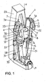
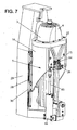
- He is represented on the figure 1 a perspective view of a molding device 1 for the blow-molding or stretch-blow molding of containers from preforms made of heated thermoplastic material.
- the molding device 1 comprises at least one mold 2 comprising at least two half-molds 3, 4 and drive means 5 (not shown in FIG. figure 1 for the sake of clarity but represented on the figures 2 , 3 and 7 ) adapted to move the half-molds 3, 4 between an open position, shown on the figures 1 and 2 , in which they are spaced from each other and a closed position, shown on the figure 3 , in which they are closely joined against each other by respective bearing faces 6, 7 defining a joint plane P and in which they define a molding cavity.
- the two half-molds 3, 4 define in their closed position a molding cavity corresponding to the imprint of the body of the blown blank.
- the two half-molds 3, 4 are articulated to each other in rotation about an axis of articulation XX contained in the joint plane P and perpendicular to the axis of the molding cavity YY, XX axis of articulation being under the two half-molds 3, 4.
- the hinge axis X-X is located below the two half-molds 3, 4 away from them. In other words, the hinge axis XX is located closer to the ground level than are the two half-molds 3, 4. Alternatively, the hinge axis XX can be directly provided through the two half -molds 3, 4.
- the molding device 1 further comprises a base 8 of fixed mold and complementary shape to the two half-molds 3, 4, so that the two half-molds 3, 4 fit into the bottom 8 of the mold in position closure for forming a sealed molding cavity.
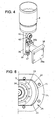
- the bottom 8 of the mold is provided fixed on a fixed upright 9 and provided substantially perpendicular to the hinge axis XX. Nevertheless, it is also possible to provide an axially movable mold base 8 adapted to fit into the two half-molds 3, 4 when they are in the closed position (see FIG. figures 5 and 6 ).
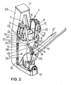
- the drive means comprises a movable member movable in a direction substantially parallel to the axis YY of the molding cavity and cooperating with the two half-molds 3, 4 so that when the moving equipment is in operation lower position, the two half-molds 3, 4 are in the open position and that when the moving equipment 10 is in the high position, the two half-molds 3, 4 are in the closed position.
- the drive means 5 comprises means 11 with follower rollers and cooperating cams provided on the lateral faces 12, 13 of the two half-molds 3, 4 in the vicinity of their respective support faces 6, 7 and on the crew 10. mobile.
- two rollers 14, 15 followers are mounted on two lateral faces 12, 13 respectively belonging to the two half-molds 3, 4 in the vicinity of their faces 6, 7 of FIG. respective support and two cams 19, 20 are provided respectively on the mobile 10.
- two follower rollers are mounted on the moving equipment and two cams are provided formed in the two faces 12, 13 side respectively belonging to the two half-molds 3, 4 in the vicinity of their respective faces 6, 7 of support.
- the molding device 1 has means 21 for locking the two half-molds 3, 4 in their closed position, each half-mold 3, 4 having an outer surface area 22 capable of abutting against an inner surface area 23 of the means 21 for locking the two half-molds 3, 4 in the closed position, the outer surface area 22 of each half-mold 3, 4 being of complementary shape to the inner surface area 23 of the locking means 21, so that, when the two surface areas 22, 23 are brought into contact one against the other, this results in the formation of two forces directed in the opposite direction radially inwards on the two half-molds 3, 4, and preferably towards the YY axis of the molding cavity, so as to implement the bracing principle, as will be described more precisely later.
- the surface areas 22, 23 are substantially frustoconical.
- the locking means 21 are incorporated in the drive means 5, namely that the locking means 21 belong to the moving equipment, which is present in the form of a sleeve 24 adapted to at least partially surround the two half-molds 3, 4.
- the locking means 21 are in any form to maintain contiguous against each other the two half-molds 3, 4, for example using piston-type means.
- the locking means 21 are in the form of a flange 25 belonging to the means 5 for driving the two half-molds 3, 4, that is to say to the mobile equipment 10, and suitable for girding the half-molds 3, 4 in the closed position.
- a roller 26 adapted to cooperate with a cam 27 is fixed on the movable member 10 so as to control the displacement of the movable member 10 in a direction substantially parallel to the Y-Y axis of the molding cavity.
- the mobile unit 10 is able to slide on at least one guide rail 28 provided fixed relative to the axis YY of the molding cavity formed in a support element or console 29 adapted to be secured to a rotating carousel thus allowing the placing a plurality of molding device 1 around the perimeter of the carousel.
- the mobile unit 10 is secured to at least one carriage 30 (preferably two carriages 30) slidable on the guide rail 28.
- Each half-mold 3, 4 comprises a low part 31 fixed to the hinge axis XX and a high part 32 comprising at least one shell holder 33 and a shell 34 in which is formed at least partially the cavity of the container to mold, the locking means 5, preferably the flange 25, of the two half-molds 3, 4 in the closed position are able to bear on the two high parts 32 of the two half-molds 3, 4.
- a stop strip 35 is fixed on the outer surface of the shell holder 33, the outer surface area of the strip 35 being able to abut against the inner surface area 23 of the locking means of the two half -molds 3, 4.
- the molding device 1 comprises biasing means, preferably piston means 44 and as described more specifically later in connection with the invention. figure 7 between the movable member 10 and the element or console 29 supporting the hinge axis XX, whereby the upward movement of the moving member 10 is facilitated from the open position to the position of closing the two half-molds 3, 4.
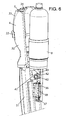
- the figure 4 represents a partial perspective view of a bottom of the mold provided axially movable and secured by securing means, as illustrated in FIG. figure 6 , to a half-mold 4 of the molding device 1 according to the invention.
- a rod 36 from the bottom 8 of the mold preferably substantially coaxial with the axis of the mold cavity, and on which is fixed, by any means known per se, a guide rail 37.
- a holding element 38 in the form of an element H with a first plate 38a fixed on the console 29 and a second plate 38b on which is fixed a carriage 39 adapted to slide on the guide rail 37 of the rod 36 of the mold base 8.
- At least one roller 40 adapted to cooperate with a cam 41 is provided fixed on the rod 36.
- At least one fixed cam 41, 43 is provided, preferably embedded in the half-mold 3, 4, in particular in the lower part 31 of the half-mold 3, 4, with a part of the cam 41, 43 projecting so as to cooperate with the rollers 40, 42.
- the projecting parts of the cams 41, 43 are shaped such that in the closed position of the half-molds 3, 4, the bottom 8 of the mold is in the up position (see FIG. figure 5 ) and that the opening movement of the half-molds 3, 4 causes an axial downward movement of the mold base 8 (see FIG. figure 6 ).
- the figure 7 is a perspective view of the molding device 1 according to the invention in which there is provided a jack 44, the rod 45 of the piston is connected to the mobile 10 and whose body is fixed on the console 29.
- the jack 44 operates between two limit pressures with a high pressure in the low position of the moving equipment, the two half-molds 3, 4 then being in their open position, and a low pressure in the high position of the machine. mobile crew 10, the two half-molds 3, 4 then being in their closed position.
- the lower chamber of the jack 44 is put under a pressure such that the moving equipment tends to undergo a thrust movement on the part of the jack 44 via its rod 45.
- He is represented on the figure 8 an upper view of a half-mold in the closed position and locked by the locking means 21.
- the abutment strip 35 is in tangential contact with the locking means 21 in the high position of the moving equipment 10, that is to say in the closed position of the two half-molds, but only outside the air-blast. the blank, the stop strip 35 being adapted to be pressed against the inner surface 23 of the locking means 21 during the blowing of the blank.
Landscapes
- Engineering & Computer Science (AREA)
- Manufacturing & Machinery (AREA)
- Mechanical Engineering (AREA)
- Moulds For Moulding Plastics Or The Like (AREA)
- Blow-Moulding Or Thermoforming Of Plastics Or The Like (AREA)
- Casting Or Compression Moulding Of Plastics Or The Like (AREA)
Claims (18)
- Formvorrichtung (1) zur Herstellung von Gefäßen durch Blasen oder Ziehen-Blasen aus Vorformen aus einem erhitzten thermoplastischen Material, wobei die Vorrichtung (1) mindestens eine Form (2), die mindestens zwei Halbformen (3, 4) umfasst, und Antriebsmittel (5), die geeignet sind, die Halbformen (3, 4) zwischen einer Öffnungsposition, in der sie voneinander entfernt sind, und einer Verschlussposition, in der sie mit jeweiligen Stützflächen (6, 7), die eine Verbindungsebene (P) definieren, eng aneinander liegen, und in der sie einen Formungshohlraum definieren, umfasst, wobei die beiden Halbformen (3, 4) aneinander in Drehung um eine Gelenkachse (X-X), die in der Verbindungsebene (P) enthalten ist und auf die Achse (Y-Y) des Formungshohlraums senkrecht steht, angelenkt sind, wobei die Gelenkachse (X-X) unter den beiden Halbformen (3, 4) angeordnet ist, wobei Verriegelungsmittel (21) der beiden Halbformen (3, 4) in ihrer Verschlussposition ebenfalls vorgesehen sind, wobei jede Halbform (3, 4) eine äußere Oberflächenzone (22) aufweist, die geeignet ist, an einer inneren Oberflächenzone (23) der Verriegelungsmittel (21) der beiden Halbformen (3, 4) in Verschlussposition zur Anlage zu gelangen, wobei die äußere Oberflächenzone (22) jeder Halbform (3, 4) eine zu der inneren Oberflächenzone (23) der Verriegelungsmittel (21) komplementäre Form hat, so dass, wenn die beiden Oberflächenzonen (22, 23) miteinander in Kontakt gebracht werden, es zur Bildung von zwei Kräften kommt, die in entgegengesetzte Richtungen radial nach innen auf die beiden Halbformen (3, 4) gerichtet sind, wobei die Verriegelungsmittel (21) in Form eines Flansches (25) vorhanden sind, der geeignet ist, die beiden Halbformen (3, 4) in Verschlussposition zu umgeben,
dadurch gekennzeichnet, dass die Antriebsmittel (5) eine bewegliche Ausrüstung (10) umfassen, die in Form einer Manschette (24) vorhanden ist, die geeignet ist, zumindest teilweise die beiden Halbformen (3, 4) zu umgeben, und die in eine Richtung im Wesentlichen parallel zur Achse (Y-Y) des Formungshohlraums beweglich ist und mit den beiden Halbformen (3, 4) zusammenwirkt, so dass, wenn sich die bewegliche Ausrüstung (10) in der unteren Position befindet, die beiden Halbformen (3, 4) in Öffnungsposition sind, und wenn die bewegliche Ausrüstung (10) in der oberen Position ist, die beiden Halbformen (3, 4) in Verschlussposition sind, und dass der Flansch (25) den Antriebsmitteln (5) der beiden Halbformen (3, 4) angehört. - Formvorrichtung nach dem vorhergehenden Anspruch 1, dadurch gekennzeichnet, dass die Oberflächenzonen (22, 23) im Wesentlichen kegelstumpfartig sind.
- Formvorrichtung nach Anspruch 1 oder 2, dadurch gekennzeichnet, dass die Gelenkachse (X-X) unter den beiden Halbformen (3, 4) in einem Abstand zu diesen angeordnet ist.
- Formvorrichtung nach einem der Ansprüche 1 bis 3, dadurch gekennzeichnet, dass die Antriebsmittel (5) Mittel (11) mit Führungsrollen und Nocken umfassen, die auf den Seitenflächen (12, 13) der beiden Halbformen (3, 4) in der Nähe ihrer jeweiligen Stützflächen (6, 7) und auf der beweglichen Ausrüstung (10) vorgesehen sind.
- Formvorrichtung nach Anspruch 4, dadurch gekennzeichnet, dass die Antriebsmittel (5) zwei Führungsrollen (14, 15), die auf zwei Seitenflächen (12, 13), die jeweils den beiden Halbformen (3, 4) angehören, in der Nähe ihrer jeweiligen Stützflächen (6, 7) montiert sind, und zwei Nocken (19, 20) umfassen, die jeweils auf der beweglichen Ausrüstung (10) vorgesehen sind.
- Formvorrichtung nach Anspruch 4, dadurch gekennzeichnet, dass die Antriebsmittel (5) zwei Führungsrollen, die auf der beweglichen Ausrüstung (10) montiert sind, und zwei Nocken umfassen, die auf zwei Seitenflächen (12, 13), die jeweils den beiden Halbformen (3, 4) angehören, in der Nähe ihrer jeweiligen Stützflächen (6, 7) vorgesehen sind.
- Formvorrichtung nach einem der Ansprüche 1 bis 6, dadurch gekennzeichnet, dass die Antriebsmittel (5) eine Rolle (26) umfassen, die geeignet ist, mit einer Nocke (27) zusammenzuwirken, und die auf der beweglichen Ausrüstung (10) derart befestigt ist, dass sie die Bewegung der beweglichen Ausrüstung (10) entlang einer Richtung im Wesentlichen parallel zur Achse (Y-Y) des Formungshohlraums steuert.
- Formvorrichtung nach einem der Ansprüche 1 bis 7, dadurch gekennzeichnet, dass die Antriebsmittel (5) mindestens eine Führungsschiene (28) umfassen, die fest in Bezug zur Gelenkachse (X-X) vorgesehen ist, und auf der die bewegliche Ausrüstung (10) gleiten kann.
- Formvorrichtung nach Anspruch 8, dadurch gekennzeichnet, dass die Führungsschiene (28) auf einem Tragelement (29) der Gelenkachse (X-X) der beiden Halbformen (3, 4) vorgesehen ist.
- Formvorrichtung nach Anspruch 9, dadurch gekennzeichnet, dass die Antriebsmittel (5) mindestens einen Schlitten (30) umfassen, der auf der Führungsschiene (28) gleiten kann und mit dem die bewegliche Ausrüstung (10) verbunden ist.
- Formvorrichtung nach einem der Ansprüche 1 bis 10, dadurch gekennzeichnet, dass sie Rückstellmittel, vorzugsweise Kolbenmittel (44), zwischen der beweglichen Ausrüstung (10) und einem Tragelement (29) der Gelenkachse (X-X) umfasst, weshalb die Bewegung der beweglichen Ausrüstung (10) von der Öffnungsposition in die Verschlussposition der beiden Halbformen (3, 4) erleichtert wird.
- Formvorrichtung nach einem der Ansprüche 1 bis 11, dadurch gekennzeichnet, dass jede Halbform (3, 4) einen unteren Teil (31), der an der Gelenkachse (X-X) befestigt ist, und einen oberen Teil (32) umfasst, der mindestens einen Schalenträger (33) und eine Schale (34) umfasst, in der der Abdruck des zu formenden Gefäßes zumindest teilweise geformt wird.
- Formvorrichtung nach Anspruch 12, dadurch gekennzeichnet, dass die Verriegelungsmittel (21) der beiden Halbformen (3, 4) in Verschlussposition geeignet sind auf den oberen Teilen (32) der beiden Halbformen (3, 4) zur Anlage zu gelangen.
- Formvorrichtung nach einem der Ansprüche 12 bis 13, dadurch gekennzeichnet, dass ein Anschlagband (35) auf der Außenseite des Schalenträgers (33) befestigt ist, wobei die äußere Oberflächenzone des Bandes (35) geeignet ist, an der inneren Oberflächenzone (23) der Verriegelungsmittel (21) der beiden Halbformen (3, 4) zur Anlage zu gelangen.
- Formvorrichtung nach einem der Ansprüche 1 bis 14, ferner umfassend einen Formboden (8), dadurch gekennzeichnet, dass der Formboden (8) axial beweglich und mit Hilfe von Verbindungsmitteln an eine der beiden Halbformen (3, 4) gekoppelt ist.
- Formvorrichtung nach Anspruch 15, dadurch gekennzeichnet, dass die Verbindungsmittel mindestens eine Rolle (40, 42) umfassen, die mit dem Formboden (8) verbunden und geeignet ist, mit mindestens einer Nocke (41, 43) zusammenzuwirken, die auf einer der beiden Halbformen (3, 4) befestigt ist, so dass der Formboden (8) in einer oberen Position ist, wenn die beiden Halbformen in ihrer Verschlussposition sind, und der Formboden (8) in einer unteren Position ist, wenn die beiden Halbformen in ihrer Öffnungsposition sind.
- Formvorrichtung nach einem der Ansprüche 15 bis 16, dadurch gekennzeichnet, dass das Anschlagband (35) mit den Verriegelungsmitteln (21) der beweglichen Ausrüstung (10) in der oberen Position, wenn kein Blasen des Rohlings stattfindet, in Tangentialkontakt ist.
- Formvorrichtung nach einem der Ansprüche 15 bis 17, dadurch gekennzeichnet, dass das Anschlagband (35) geeignet ist, an die Innenfläche (23) der Verriegelungsmittel (21) beim Blasen des Rohlings angelegt zu werden.
Applications Claiming Priority (2)
| Application Number | Priority Date | Filing Date | Title |
|---|---|---|---|
| FR0701396A FR2912952B1 (fr) | 2007-02-27 | 2007-02-27 | Dispositif de moulage pour la fabrication de recipients en materiau thermoplastique |
| PCT/FR2008/050274 WO2008113932A2 (fr) | 2007-02-27 | 2008-02-19 | Dispositif de moulage pour la fabrication de recipients en materiau thermoplastique |
Publications (2)
| Publication Number | Publication Date |
|---|---|
| EP2125331A2 EP2125331A2 (de) | 2009-12-02 |
| EP2125331B1 true EP2125331B1 (de) | 2015-07-22 |
Family
ID=38567045
Family Applications (1)
| Application Number | Title | Priority Date | Filing Date |
|---|---|---|---|
| EP08762122.3A Not-in-force EP2125331B1 (de) | 2007-02-27 | 2008-02-19 | Formvorrichtung zur herstellung von gefässen aus einem thermoplastischen material |
Country Status (7)
| Country | Link |
|---|---|
| US (1) | US8215948B2 (de) |
| EP (1) | EP2125331B1 (de) |
| JP (1) | JP5028498B2 (de) |
| CN (1) | CN101663151B (de) |
| FR (1) | FR2912952B1 (de) |
| MX (1) | MX2009009102A (de) |
| WO (1) | WO2008113932A2 (de) |
Families Citing this family (7)
| Publication number | Priority date | Publication date | Assignee | Title |
|---|---|---|---|---|
| FR2926035B1 (fr) | 2008-01-09 | 2017-02-03 | Sidel Participations | Fond de moule pour moule de fabrication de recipients thermoplastiques, et dispositif de moulage equipe d'au moins un moule pourvu d'un tel fond |
| FR2945979A1 (fr) | 2009-05-29 | 2010-12-03 | Sidel Participations | Dispositif de moulage avec circuit(s) de fluide |
| DE102010039802A1 (de) | 2010-08-26 | 2012-03-01 | Krones Aktiengesellschaft | Blasform |
| DE102010040004A1 (de) | 2010-08-31 | 2012-03-01 | Krones Aktiengesellschaft | Blasform |
| FR2972386B1 (fr) | 2011-03-08 | 2014-10-10 | Sidel Participations | Systeme d'assistance au changement de moule d'unite de moulage d'une machine de fabrication de recipients |
| DE102011104316A1 (de) * | 2011-06-03 | 2012-12-06 | Krones Aktiengesellschaft | Vorrichtung und Anlage zum Steckblasen von Kunststoffvorformlingen sowie Verwendung eines Keramikbauteils |
| DE202013009941U1 (de) | 2012-11-12 | 2013-11-20 | Khs Corpoplast Gmbh | Vorrichtung zur Blasformung von Behältern mit einer Antriebseinrichtung und mit gekoppelten Bewegungsabläufen |
Family Cites Families (16)
| Publication number | Priority date | Publication date | Assignee | Title |
|---|---|---|---|---|
| GB763583A (en) * | 1951-12-17 | 1956-12-12 | Francis Trigg Parfrey | A new and improved method of and means for forming hollow articles from thermoplastic material by blowing |
| BE642610A (de) * | 1959-07-02 | |||
| US3344475A (en) * | 1965-11-08 | 1967-10-03 | Salvatore M Gioe | Apparatus for shaping materials and substances into a round ball |
| DE1943874A1 (de) * | 1969-08-29 | 1971-03-11 | Fischer Rainer | Vorrichtung zum Herstellen von Hohlkoerpern aus thermoplastischem Kunststoff |
| US3881855A (en) * | 1973-01-16 | 1975-05-06 | Francis Farkas | Injection blow molding apparatus |
| CA987463A (en) * | 1973-11-05 | 1976-04-20 | Walter C. Diener | Molding machine |
| US4764328A (en) * | 1987-03-23 | 1988-08-16 | Ford Motor Company | Method of fusion bonding low density thermoplastic bodies |
| JPH0957838A (ja) * | 1995-08-29 | 1997-03-04 | Kyoraku Co Ltd | 中空体の製造方法およびその装置 |
| EP1056585A1 (de) * | 1997-12-23 | 2000-12-06 | Coraltech Limited | Tiefziehen oder blasformen von einspritz-vorformlingen |
| IT1305267B1 (it) * | 1998-06-03 | 2001-04-19 | Sipa Spa | Impianto perfezionato per la produzione di contenitori in resinatermoplastica. |
| IT1311703B1 (it) * | 1999-07-23 | 2002-03-19 | Sipa Spa | Impianto ad alta efficienza di soffiaggio di preforme |
| US7101168B1 (en) | 1999-09-08 | 2006-09-05 | Weasy Pack International Ltd. | Releasing undercut moulded containers after a thermoforming process |
| FR2813231B1 (fr) | 2000-08-31 | 2003-05-09 | Sidel Sa | Unite de moulage comportant une chambre de compensation delimitee par une membrane, membrane pour une telle unite et machine munie d'une telle unite |
| FR2833512B1 (fr) * | 2001-12-13 | 2004-02-27 | Sidel Sa | Installation de soufflage de recipients en polymere termoplastique |
| FR2841495B1 (fr) | 2002-06-27 | 2004-11-12 | Sidel Sa | Dispositif de moulage, par soufflage ou etirage-soufflage, de recipients en matiere thermoplastique |
| FR2863930B1 (fr) | 2003-12-19 | 2006-03-03 | Sidel Sa | Dispositif de moulage pour la fabrication de recipients en materiau thermoplastique |
-
2007
- 2007-02-27 FR FR0701396A patent/FR2912952B1/fr not_active Expired - Fee Related
-
2008
- 2008-02-19 MX MX2009009102A patent/MX2009009102A/es active IP Right Grant
- 2008-02-19 EP EP08762122.3A patent/EP2125331B1/de not_active Not-in-force
- 2008-02-19 WO PCT/FR2008/050274 patent/WO2008113932A2/fr not_active Ceased
- 2008-02-19 CN CN200880009675.5A patent/CN101663151B/zh not_active Expired - Fee Related
- 2008-02-19 US US12/528,716 patent/US8215948B2/en not_active Expired - Fee Related
- 2008-02-19 JP JP2009551242A patent/JP5028498B2/ja not_active Expired - Fee Related
Also Published As
| Publication number | Publication date |
|---|---|
| US20100047375A1 (en) | 2010-02-25 |
| FR2912952A1 (fr) | 2008-08-29 |
| CN101663151B (zh) | 2012-10-03 |
| WO2008113932A2 (fr) | 2008-09-25 |
| JP2010519092A (ja) | 2010-06-03 |
| WO2008113932A3 (fr) | 2009-03-26 |
| JP5028498B2 (ja) | 2012-09-19 |
| MX2009009102A (es) | 2009-09-04 |
| CN101663151A (zh) | 2010-03-03 |
| US8215948B2 (en) | 2012-07-10 |
| EP2125331A2 (de) | 2009-12-02 |
| FR2912952B1 (fr) | 2013-08-16 |
Similar Documents
| Publication | Publication Date | Title |
|---|---|---|
| EP2125331B1 (de) | Formvorrichtung zur herstellung von gefässen aus einem thermoplastischen material | |
| EP1216136B1 (de) | Blasformmaschine mit einem schliess- und verriegelungsmechanismus | |
| EP1636006B1 (de) | Formvorrichtung zur herstellung von behältern aus thermoplastischem material | |
| EP1246718B1 (de) | Rotationsstreckblasmaschine mit einem magnetisch angetriebenen streckhelfer | |
| FR2841495A1 (fr) | Dispositif de moulage, par soufflage ou etirage-soufflage, de recipients en matiere thermoplastique | |
| FR2949703A1 (fr) | Dispositif de moulage equipe de moyens de fixation d'un demi-moule par attaction contre le fond d'un logement associe d'un porte-moule | |
| EP3057767A1 (de) | Formeinheit zur herstellung von behältern mit einem kompensationsgreifer | |
| EP1924421B1 (de) | Lineare formeinheit für eine behälterfabrikationsanlage | |
| FR2889820A1 (fr) | Moule de soufflage pour recipients thermoplastiques munis d'une poignee integrale, installation equipee de tels moules, et recipient fabrique avec un tel moule | |
| EP1200243B1 (de) | Blasformmaschine mit zwei formkavitäten | |
| EP1523404B1 (de) | Verfahren und vorrichtung zum warmumformen von einem gegenstand der eine hinterschneidung aufweist | |
| EP1919689A1 (de) | Blasformstation für eine behälterstreck-/blasanlage und anlage mit einer derartigen anordnung | |
| EP2111967B1 (de) | Vorrichtung zum Formgießen von Behältern einschließlich Mittel zum Regulieren der Volumenmaße des zu formenden Hohlraums | |
| EP3131734A1 (de) | Giesseinheit mit formbodenbetätigungseinrichtung auf einer fixen halterung | |
| WO2012016951A1 (fr) | Machine de formage équipée d'une unité de moulage comportant des moyens de compensation commandés par au moins une vanne à actionnement automatique | |
| EP2244872B1 (de) | Formwerkzeug für eine rotationsformmaschine und rotationsformmaschine mit einem solchen formwerkzeug | |
| EP3173212B1 (de) | Verfahren zur steuerung einer spritzguss-einheit | |
| EP2475510B1 (de) | Formgerät mit vorrichtung zur befestigung einer halbform an einem formhalter mittels verriegelung | |
| WO2006064103A1 (fr) | Unite de moulage de type lineaire pour une installation de fabrication de recipients | |
| EP1384563B1 (de) | Verfahren zur Herstellung eines hohlen dekorierten Behälters mit Nachverformung in einem Formwerkzeug | |
| EP4121271B1 (de) | Vorrichtung und verfahren zur herstellung eines behälters durch blasformen oder streckblasformen | |
| EP3727795B1 (de) | Halbform mit zylindrischer montagefläche und herstellungsverfahren | |
| EP3019326B1 (de) | Einheit zum formen von behältern aus einem thermoplastischen kunststoff mit kompensationsvorrichtung | |
| FR2798880A1 (fr) | Machine rotative d'extrusion-soufflage a moules basculants | |
| EP4457072A1 (de) | Verbesserung an einer formeinheit mit beweglichem überziehkolbeneinsatz |
Legal Events
| Date | Code | Title | Description |
|---|---|---|---|
| PUAI | Public reference made under article 153(3) epc to a published international application that has entered the european phase |
Free format text: ORIGINAL CODE: 0009012 |
|
| 17P | Request for examination filed |
Effective date: 20090817 |
|
| AK | Designated contracting states |
Kind code of ref document: A2 Designated state(s): AT BE BG CH CY CZ DE DK EE ES FI FR GB GR HR HU IE IS IT LI LT LU LV MC MT NL NO PL PT RO SE SI SK TR |
|
| 17Q | First examination report despatched |
Effective date: 20100323 |
|
| DAX | Request for extension of the european patent (deleted) | ||
| GRAP | Despatch of communication of intention to grant a patent |
Free format text: ORIGINAL CODE: EPIDOSNIGR1 |
|
| INTG | Intention to grant announced |
Effective date: 20150414 |
|
| GRAS | Grant fee paid |
Free format text: ORIGINAL CODE: EPIDOSNIGR3 |
|
| GRAA | (expected) grant |
Free format text: ORIGINAL CODE: 0009210 |
|
| AK | Designated contracting states |
Kind code of ref document: B1 Designated state(s): AT BE BG CH CY CZ DE DK EE ES FI FR GB GR HR HU IE IS IT LI LT LU LV MC MT NL NO PL PT RO SE SI SK TR |
|
| REG | Reference to a national code |
Ref country code: GB Ref legal event code: FG4D Free format text: NOT ENGLISH |
|
| REG | Reference to a national code |
Ref country code: CH Ref legal event code: EP |
|
| REG | Reference to a national code |
Ref country code: IE Ref legal event code: FG4D Free format text: LANGUAGE OF EP DOCUMENT: FRENCH |
|
| REG | Reference to a national code |
Ref country code: AT Ref legal event code: REF Ref document number: 737626 Country of ref document: AT Kind code of ref document: T Effective date: 20150815 |
|
| REG | Reference to a national code |
Ref country code: DE Ref legal event code: R096 Ref document number: 602008039136 Country of ref document: DE |
|
| REG | Reference to a national code |
Ref country code: AT Ref legal event code: MK05 Ref document number: 737626 Country of ref document: AT Kind code of ref document: T Effective date: 20150722 |
|
| REG | Reference to a national code |
Ref country code: LT Ref legal event code: MG4D |
|
| REG | Reference to a national code |
Ref country code: NL Ref legal event code: MP Effective date: 20150722 |
|
| PG25 | Lapsed in a contracting state [announced via postgrant information from national office to epo] |
Ref country code: GR Free format text: LAPSE BECAUSE OF FAILURE TO SUBMIT A TRANSLATION OF THE DESCRIPTION OR TO PAY THE FEE WITHIN THE PRESCRIBED TIME-LIMIT Effective date: 20151023 Ref country code: FI Free format text: LAPSE BECAUSE OF FAILURE TO SUBMIT A TRANSLATION OF THE DESCRIPTION OR TO PAY THE FEE WITHIN THE PRESCRIBED TIME-LIMIT Effective date: 20150722 Ref country code: LV Free format text: LAPSE BECAUSE OF FAILURE TO SUBMIT A TRANSLATION OF THE DESCRIPTION OR TO PAY THE FEE WITHIN THE PRESCRIBED TIME-LIMIT Effective date: 20150722 Ref country code: LT Free format text: LAPSE BECAUSE OF FAILURE TO SUBMIT A TRANSLATION OF THE DESCRIPTION OR TO PAY THE FEE WITHIN THE PRESCRIBED TIME-LIMIT Effective date: 20150722 Ref country code: NO Free format text: LAPSE BECAUSE OF FAILURE TO SUBMIT A TRANSLATION OF THE DESCRIPTION OR TO PAY THE FEE WITHIN THE PRESCRIBED TIME-LIMIT Effective date: 20151022 |
|
| PG25 | Lapsed in a contracting state [announced via postgrant information from national office to epo] |
Ref country code: PT Free format text: LAPSE BECAUSE OF FAILURE TO SUBMIT A TRANSLATION OF THE DESCRIPTION OR TO PAY THE FEE WITHIN THE PRESCRIBED TIME-LIMIT Effective date: 20151123 Ref country code: IS Free format text: LAPSE BECAUSE OF FAILURE TO SUBMIT A TRANSLATION OF THE DESCRIPTION OR TO PAY THE FEE WITHIN THE PRESCRIBED TIME-LIMIT Effective date: 20151122 Ref country code: AT Free format text: LAPSE BECAUSE OF FAILURE TO SUBMIT A TRANSLATION OF THE DESCRIPTION OR TO PAY THE FEE WITHIN THE PRESCRIBED TIME-LIMIT Effective date: 20150722 Ref country code: HR Free format text: LAPSE BECAUSE OF FAILURE TO SUBMIT A TRANSLATION OF THE DESCRIPTION OR TO PAY THE FEE WITHIN THE PRESCRIBED TIME-LIMIT Effective date: 20150722 Ref country code: PL Free format text: LAPSE BECAUSE OF FAILURE TO SUBMIT A TRANSLATION OF THE DESCRIPTION OR TO PAY THE FEE WITHIN THE PRESCRIBED TIME-LIMIT Effective date: 20150722 Ref country code: SE Free format text: LAPSE BECAUSE OF FAILURE TO SUBMIT A TRANSLATION OF THE DESCRIPTION OR TO PAY THE FEE WITHIN THE PRESCRIBED TIME-LIMIT Effective date: 20150722 Ref country code: ES Free format text: LAPSE BECAUSE OF FAILURE TO SUBMIT A TRANSLATION OF THE DESCRIPTION OR TO PAY THE FEE WITHIN THE PRESCRIBED TIME-LIMIT Effective date: 20150722 |
|
| REG | Reference to a national code |
Ref country code: DE Ref legal event code: R097 Ref document number: 602008039136 Country of ref document: DE |
|
| PG25 | Lapsed in a contracting state [announced via postgrant information from national office to epo] |
Ref country code: SK Free format text: LAPSE BECAUSE OF FAILURE TO SUBMIT A TRANSLATION OF THE DESCRIPTION OR TO PAY THE FEE WITHIN THE PRESCRIBED TIME-LIMIT Effective date: 20150722 Ref country code: IT Free format text: LAPSE BECAUSE OF FAILURE TO SUBMIT A TRANSLATION OF THE DESCRIPTION OR TO PAY THE FEE WITHIN THE PRESCRIBED TIME-LIMIT Effective date: 20150722 Ref country code: CZ Free format text: LAPSE BECAUSE OF FAILURE TO SUBMIT A TRANSLATION OF THE DESCRIPTION OR TO PAY THE FEE WITHIN THE PRESCRIBED TIME-LIMIT Effective date: 20150722 Ref country code: DK Free format text: LAPSE BECAUSE OF FAILURE TO SUBMIT A TRANSLATION OF THE DESCRIPTION OR TO PAY THE FEE WITHIN THE PRESCRIBED TIME-LIMIT Effective date: 20150722 Ref country code: EE Free format text: LAPSE BECAUSE OF FAILURE TO SUBMIT A TRANSLATION OF THE DESCRIPTION OR TO PAY THE FEE WITHIN THE PRESCRIBED TIME-LIMIT Effective date: 20150722 |
|
| PLBE | No opposition filed within time limit |
Free format text: ORIGINAL CODE: 0009261 |
|
| STAA | Information on the status of an ep patent application or granted ep patent |
Free format text: STATUS: NO OPPOSITION FILED WITHIN TIME LIMIT |
|
| PG25 | Lapsed in a contracting state [announced via postgrant information from national office to epo] |
Ref country code: RO Free format text: LAPSE BECAUSE OF FAILURE TO SUBMIT A TRANSLATION OF THE DESCRIPTION OR TO PAY THE FEE WITHIN THE PRESCRIBED TIME-LIMIT Effective date: 20150722 Ref country code: BE Free format text: LAPSE BECAUSE OF NON-PAYMENT OF DUE FEES Effective date: 20160229 |
|
| 26N | No opposition filed |
Effective date: 20160425 |
|
| PG25 | Lapsed in a contracting state [announced via postgrant information from national office to epo] |
Ref country code: SI Free format text: LAPSE BECAUSE OF FAILURE TO SUBMIT A TRANSLATION OF THE DESCRIPTION OR TO PAY THE FEE WITHIN THE PRESCRIBED TIME-LIMIT Effective date: 20150722 |
|
| REG | Reference to a national code |
Ref country code: DE Ref legal event code: R119 Ref document number: 602008039136 Country of ref document: DE |
|
| PG25 | Lapsed in a contracting state [announced via postgrant information from national office to epo] |
Ref country code: LU Free format text: LAPSE BECAUSE OF FAILURE TO SUBMIT A TRANSLATION OF THE DESCRIPTION OR TO PAY THE FEE WITHIN THE PRESCRIBED TIME-LIMIT Effective date: 20160219 Ref country code: MC Free format text: LAPSE BECAUSE OF FAILURE TO SUBMIT A TRANSLATION OF THE DESCRIPTION OR TO PAY THE FEE WITHIN THE PRESCRIBED TIME-LIMIT Effective date: 20150722 |
|
| REG | Reference to a national code |
Ref country code: CH Ref legal event code: PL |
|
| GBPC | Gb: european patent ceased through non-payment of renewal fee |
Effective date: 20160219 |
|
| PG25 | Lapsed in a contracting state [announced via postgrant information from national office to epo] |
Ref country code: CH Free format text: LAPSE BECAUSE OF NON-PAYMENT OF DUE FEES Effective date: 20160229 Ref country code: LI Free format text: LAPSE BECAUSE OF NON-PAYMENT OF DUE FEES Effective date: 20160229 |
|
| REG | Reference to a national code |
Ref country code: FR Ref legal event code: ST Effective date: 20161028 |
|
| REG | Reference to a national code |
Ref country code: IE Ref legal event code: MM4A |
|
| PG25 | Lapsed in a contracting state [announced via postgrant information from national office to epo] |
Ref country code: FR Free format text: LAPSE BECAUSE OF NON-PAYMENT OF DUE FEES Effective date: 20160229 Ref country code: IE Free format text: LAPSE BECAUSE OF NON-PAYMENT OF DUE FEES Effective date: 20160219 Ref country code: DE Free format text: LAPSE BECAUSE OF NON-PAYMENT OF DUE FEES Effective date: 20160901 Ref country code: GB Free format text: LAPSE BECAUSE OF NON-PAYMENT OF DUE FEES Effective date: 20160219 |
|
| PG25 | Lapsed in a contracting state [announced via postgrant information from national office to epo] |
Ref country code: NL Free format text: LAPSE BECAUSE OF FAILURE TO SUBMIT A TRANSLATION OF THE DESCRIPTION OR TO PAY THE FEE WITHIN THE PRESCRIBED TIME-LIMIT Effective date: 20150722 |
|
| PG25 | Lapsed in a contracting state [announced via postgrant information from national office to epo] |
Ref country code: MT Free format text: LAPSE BECAUSE OF FAILURE TO SUBMIT A TRANSLATION OF THE DESCRIPTION OR TO PAY THE FEE WITHIN THE PRESCRIBED TIME-LIMIT Effective date: 20150722 |
|
| PG25 | Lapsed in a contracting state [announced via postgrant information from national office to epo] |
Ref country code: HU Free format text: LAPSE BECAUSE OF FAILURE TO SUBMIT A TRANSLATION OF THE DESCRIPTION OR TO PAY THE FEE WITHIN THE PRESCRIBED TIME-LIMIT; INVALID AB INITIO Effective date: 20080219 Ref country code: CY Free format text: LAPSE BECAUSE OF FAILURE TO SUBMIT A TRANSLATION OF THE DESCRIPTION OR TO PAY THE FEE WITHIN THE PRESCRIBED TIME-LIMIT Effective date: 20150722 |
|
| PG25 | Lapsed in a contracting state [announced via postgrant information from national office to epo] |
Ref country code: TR Free format text: LAPSE BECAUSE OF FAILURE TO SUBMIT A TRANSLATION OF THE DESCRIPTION OR TO PAY THE FEE WITHIN THE PRESCRIBED TIME-LIMIT Effective date: 20150722 |
|
| PG25 | Lapsed in a contracting state [announced via postgrant information from national office to epo] |
Ref country code: BG Free format text: LAPSE BECAUSE OF FAILURE TO SUBMIT A TRANSLATION OF THE DESCRIPTION OR TO PAY THE FEE WITHIN THE PRESCRIBED TIME-LIMIT Effective date: 20150722 |