EP2125331B1 - Moulding device for making vessels of a thermoplastic material - Google Patents
Moulding device for making vessels of a thermoplastic material Download PDFInfo
- Publication number
- EP2125331B1 EP2125331B1 EP08762122.3A EP08762122A EP2125331B1 EP 2125331 B1 EP2125331 B1 EP 2125331B1 EP 08762122 A EP08762122 A EP 08762122A EP 2125331 B1 EP2125331 B1 EP 2125331B1
- Authority
- EP
- European Patent Office
- Prior art keywords
- moulds
- moulding device
- molds
- mobile assembly
- closed position
- Prior art date
- Legal status (The legal status is an assumption and is not a legal conclusion. Google has not performed a legal analysis and makes no representation as to the accuracy of the status listed.)
- Not-in-force
Links
Images


Classifications
-
- B—PERFORMING OPERATIONS; TRANSPORTING
- B29—WORKING OF PLASTICS; WORKING OF SUBSTANCES IN A PLASTIC STATE IN GENERAL
- B29C—SHAPING OR JOINING OF PLASTICS; SHAPING OF MATERIAL IN A PLASTIC STATE, NOT OTHERWISE PROVIDED FOR; AFTER-TREATMENT OF THE SHAPED PRODUCTS, e.g. REPAIRING
- B29C49/00—Blow-moulding, i.e. blowing a preform or parison to a desired shape within a mould; Apparatus therefor
- B29C49/42—Component parts, details or accessories; Auxiliary operations
- B29C49/56—Opening, closing or clamping means
-
- B—PERFORMING OPERATIONS; TRANSPORTING
- B29—WORKING OF PLASTICS; WORKING OF SUBSTANCES IN A PLASTIC STATE IN GENERAL
- B29C—SHAPING OR JOINING OF PLASTICS; SHAPING OF MATERIAL IN A PLASTIC STATE, NOT OTHERWISE PROVIDED FOR; AFTER-TREATMENT OF THE SHAPED PRODUCTS, e.g. REPAIRING
- B29C49/00—Blow-moulding, i.e. blowing a preform or parison to a desired shape within a mould; Apparatus therefor
- B29C49/42—Component parts, details or accessories; Auxiliary operations
- B29C49/48—Moulds
- B29C2049/4879—Moulds characterised by mould configurations
- B29C2049/4892—Mould halves consisting of an independent main and bottom part
-
- B—PERFORMING OPERATIONS; TRANSPORTING
- B29—WORKING OF PLASTICS; WORKING OF SUBSTANCES IN A PLASTIC STATE IN GENERAL
- B29C—SHAPING OR JOINING OF PLASTICS; SHAPING OF MATERIAL IN A PLASTIC STATE, NOT OTHERWISE PROVIDED FOR; AFTER-TREATMENT OF THE SHAPED PRODUCTS, e.g. REPAIRING
- B29C49/00—Blow-moulding, i.e. blowing a preform or parison to a desired shape within a mould; Apparatus therefor
- B29C49/42—Component parts, details or accessories; Auxiliary operations
- B29C49/56—Opening, closing or clamping means
- B29C2049/5636—Opening, closing or clamping means using closing means as clamping means
-
- B—PERFORMING OPERATIONS; TRANSPORTING
- B29—WORKING OF PLASTICS; WORKING OF SUBSTANCES IN A PLASTIC STATE IN GENERAL
- B29C—SHAPING OR JOINING OF PLASTICS; SHAPING OF MATERIAL IN A PLASTIC STATE, NOT OTHERWISE PROVIDED FOR; AFTER-TREATMENT OF THE SHAPED PRODUCTS, e.g. REPAIRING
- B29C2949/00—Indexing scheme relating to blow-moulding
- B29C2949/07—Preforms or parisons characterised by their configuration
- B29C2949/0715—Preforms or parisons characterised by their configuration the preform having one end closed
-
- B—PERFORMING OPERATIONS; TRANSPORTING
- B29—WORKING OF PLASTICS; WORKING OF SUBSTANCES IN A PLASTIC STATE IN GENERAL
- B29C—SHAPING OR JOINING OF PLASTICS; SHAPING OF MATERIAL IN A PLASTIC STATE, NOT OTHERWISE PROVIDED FOR; AFTER-TREATMENT OF THE SHAPED PRODUCTS, e.g. REPAIRING
- B29C33/00—Moulds or cores; Details thereof or accessories therefor
- B29C33/20—Opening, closing or clamping
- B29C33/26—Opening, closing or clamping by pivotal movement
-
- B—PERFORMING OPERATIONS; TRANSPORTING
- B29—WORKING OF PLASTICS; WORKING OF SUBSTANCES IN A PLASTIC STATE IN GENERAL
- B29C—SHAPING OR JOINING OF PLASTICS; SHAPING OF MATERIAL IN A PLASTIC STATE, NOT OTHERWISE PROVIDED FOR; AFTER-TREATMENT OF THE SHAPED PRODUCTS, e.g. REPAIRING
- B29C49/00—Blow-moulding, i.e. blowing a preform or parison to a desired shape within a mould; Apparatus therefor
- B29C49/02—Combined blow-moulding and manufacture of the preform or the parison
- B29C49/06—Injection blow-moulding
-
- B—PERFORMING OPERATIONS; TRANSPORTING
- B29—WORKING OF PLASTICS; WORKING OF SUBSTANCES IN A PLASTIC STATE IN GENERAL
- B29C—SHAPING OR JOINING OF PLASTICS; SHAPING OF MATERIAL IN A PLASTIC STATE, NOT OTHERWISE PROVIDED FOR; AFTER-TREATMENT OF THE SHAPED PRODUCTS, e.g. REPAIRING
- B29C49/00—Blow-moulding, i.e. blowing a preform or parison to a desired shape within a mould; Apparatus therefor
- B29C49/28—Blow-moulding apparatus
- B29C49/30—Blow-moulding apparatus having movable moulds or mould parts
- B29C49/36—Blow-moulding apparatus having movable moulds or mould parts rotatable about one axis
-
- B—PERFORMING OPERATIONS; TRANSPORTING
- B29—WORKING OF PLASTICS; WORKING OF SUBSTANCES IN A PLASTIC STATE IN GENERAL
- B29C—SHAPING OR JOINING OF PLASTICS; SHAPING OF MATERIAL IN A PLASTIC STATE, NOT OTHERWISE PROVIDED FOR; AFTER-TREATMENT OF THE SHAPED PRODUCTS, e.g. REPAIRING
- B29C49/00—Blow-moulding, i.e. blowing a preform or parison to a desired shape within a mould; Apparatus therefor
- B29C49/42—Component parts, details or accessories; Auxiliary operations
- B29C49/56—Opening, closing or clamping means
- B29C49/5601—Mechanically operated, i.e. closing or opening of the mould parts is done by mechanic means
- B29C49/5602—Mechanically operated, i.e. closing or opening of the mould parts is done by mechanic means using cams
-
- B—PERFORMING OPERATIONS; TRANSPORTING
- B29—WORKING OF PLASTICS; WORKING OF SUBSTANCES IN A PLASTIC STATE IN GENERAL
- B29C—SHAPING OR JOINING OF PLASTICS; SHAPING OF MATERIAL IN A PLASTIC STATE, NOT OTHERWISE PROVIDED FOR; AFTER-TREATMENT OF THE SHAPED PRODUCTS, e.g. REPAIRING
- B29C49/00—Blow-moulding, i.e. blowing a preform or parison to a desired shape within a mould; Apparatus therefor
- B29C49/42—Component parts, details or accessories; Auxiliary operations
- B29C49/56—Opening, closing or clamping means
- B29C49/561—Characterised by speed, e.g. variable opening closing speed
-
- Y—GENERAL TAGGING OF NEW TECHNOLOGICAL DEVELOPMENTS; GENERAL TAGGING OF CROSS-SECTIONAL TECHNOLOGIES SPANNING OVER SEVERAL SECTIONS OF THE IPC; TECHNICAL SUBJECTS COVERED BY FORMER USPC CROSS-REFERENCE ART COLLECTIONS [XRACs] AND DIGESTS
- Y10—TECHNICAL SUBJECTS COVERED BY FORMER USPC
- Y10S—TECHNICAL SUBJECTS COVERED BY FORMER USPC CROSS-REFERENCE ART COLLECTIONS [XRACs] AND DIGESTS
- Y10S425/00—Plastic article or earthenware shaping or treating: apparatus
- Y10S425/005—Cammed
Definitions
- the present invention generally relates to the field of molding devices for the blow-molding or stretch-blow molding of containers from preforms of heated thermoplastic material.
- the invention relates to molding devices comprising at least one mold comprising at least two half-molds movable mutually between an open position in which they are spaced from one another and a closed position in which they are closely joined against each other by respective bearing faces defining a joint plane.
- a first molding device relates to molding devices with a crocodile-type opening, that is to say with one half of the molding device which is fixed on a rotary rotating carousel, another half removable pivotally in a downward movement directed radially outwardly and an axially removable mold bottom.
- this molding device because of its opening of the movable half radially outward, causes a very penalizing centrifugal force and requires relatively accurate settings for synchronism with the movement of the mold bottom.
- a second type of molding device relates to opening type molding devices in the portfolio, particularly as described in document FR 2 863 930 , in which the molding device comprises two half-molds with at least two respective edges with their respective bearing faces which are arranged in the form of two overlapping edges with respective faces cooperating vis-à-vis radial in the closed position of the mold, locking means being operatively associated with said overlapped edges so as to prevent the opening of the mold during the blowing operation of the container.
- the two half-molds are articulated mutually in rotation on a shaft substantially parallel to one side of the joint plane and the locking means are provided on the side of the mold opposite said shaft of the two half-molds.
- each half-mold comprises a mold-holder to which is fixed internally a shell provided with a half-cavity molding, the joint plane being defined by the two shells contiguous in the closed position of the mold and the means of locking are supported by the two mold holders.
- wall-type molding devices comprising a mold in three parts, namely two half-molds for the body of the container and a bottom of the mold for the bottom of the container, the lower parts of the two halves. molds and the upper part of the mold bottom having mutually engageable means in the closed position of the mold to ensure the axial rigidity of the mold in the presence of the blowing pressure.
- the document FR-1238421 discloses a molding device according to the preamble of claim 1.
- Molding devices known in the prior art although satisfactory from the point of view of the quality of the molded container, have certain drawbacks leading to a major brake in increasing the rate of production of the containers molded per hour from these molding devices.
- the kinematic chain of the transfer of the container to the molding device to the final receiver of the molded container is relatively long and involves the presence of many parts in series.
- the control of the opening and closing means as well as the control of the locking and unlocking means of the molding devices are carried out with the aid of a first double cam and roller assembly for control of the opening and closing and a second respective cam and roller assembly for controlling the locking and unlocking, the two assemblies being controlled independently of one another mechanically, this which is likely to quadruple adjustment problems and cause a loss of time during this adjustment. It would therefore be particularly advantageous to make a molding device whose opening and closing operations as well as the locking and unlocking operations of the molding device are performed by a single command.
- the locking / unlocking means of the molding devices generally provided along a respective edge of the half-molds, occupy a volume of space likely to affect the transfer of the container once it is molded.
- locking / unlocking means currently used are often associated with locking fingers which should be changed regularly because of their wear.
- the document FR 2 813 231 has a molding device comprising, between two entities constituted by a mold element and its support, a compensation chamber in which a fluid under pressure is injected to move the mold element from its support, the chamber being arranged between at least one of the mold members and the associated holder for pushing the mold member transversely from a retracted position to an advanced position towards the other member.
- the clearing house does not compensate for bottles larger than 1.5 liters.
- the compensation chamber is only present on a half-mold, it is possible to have a shift of the joint planes due to the inhomogeneity of the rigidities between the two half-molds.
- this clearing house is relatively complex to form and achieve. It would therefore be particularly advantageous to provide a molding device that does not require the presence of a compensation chamber between the mold support and the mold block of a half-mold.
- the thermal efficiency of the molding devices according to the prior art is reduced because of the presence of numerous exchanges of heat flows between the at least two half-molds and the mold bottom, this yield being all the more diminished.
- HR heat resistant blow molding configuration since in this case the mold bottom is cooled and the at least two half-molds are heated.
- Molding devices such as currently achieved can achieve a maximum rate of 1800 bottles per hour and per molding device, due to the presence of numerous dynamic errors, including vibration problems and deformation of the control systems. cam and roller, as well as problems of load and wear of the molding devices.
- the tolerance of the settings is also very low, that is to say of the order of a tenth of a millimeter. It would therefore be particularly advantageous to make a molding device with greater adjustment tolerances.
- the total height of the clearing room is also limited, as are the delicate settings.
- the present invention relates to a molding device for the blow-molding or stretch-blow molding of containers from preforms made of heated thermoplastic material, said device comprising at least one mold comprising at least two semi-molds.
- each half-mold having an outer surface area adapted to abut against an inner surface area of locking means of the two half-molds in the closed position, the outer surface area of each half-mold being complementary in shape to the inner surface area of the locking means, so that when the two surface areas are brought into contact with each other, this results in the formation of two counter-radially inward-facing forces on the two half-molds and the said locking means being in the form of a
- the surface areas are substantially frustoconical.
- the axis of articulation is located below the two half-molds at a distance from them.
- the drive means comprise follower and cooperating cam follower means provided on the lateral faces of the two half-molds in the vicinity of their respective bearing faces and on the moving equipment.
- two follower rollers are mounted on two lateral faces respectively belonging to the two half-molds in the vicinity of their respective bearing faces and two cams are respectively provided on the moving element. .
- two follower rollers are mounted on the moving element and two cams are provided on two lateral faces respectively belonging to the two half-molds in the vicinity of their respective bearing faces.
- the surface zones are substantially frustoconical.
- a roller adapted to cooperate with a cam is fixed on the moving element.
- the mobile assembly is able to slide on at least one guide rail provided fixed relative to the hinge axis.
- the guide rail is provided on a support member of the hinge axis of the two half-molds.
- the moving element is secured to at least one carriage slidable on the guide rail.
- the molding device comprises biasing means, preferably piston means, between the movable element and a support element of the articulation axis.
- each half-mold comprises a lower part fixed to the hinge axis and an upper part comprising at least one shell holder and a shell in which is formed less partially the impression of the container to be molded.
- the locking means of the two half-molds in the closed position are able to bear on the upper parts of the two half-molds.
- a stop strip is fixed on the outer surface of the shell holder, the outer surface area of the strip being adapted to abut against the inner surface area of the locking means of the two half-molds .
- the molding device comprises an axially movable mold bottom and coupled by means of securing means to one of the two half-molds.
- the securing means comprise at least one roller, secured to the mold base, adapted to cooperate with at least one cam fixed on one of the two half-molds, so that the mold bottom is in a high position when the two half-molds are in their closed position and the mold bottom is in a low position when the two half-molds are in their open position.
- the stop strip is in tangential contact with the locking means in the high position of the moving element outside the blowing of the blank.
- the stop strip is adapted to be pressed against the inner surface of the locking means during the blowing of the blank.
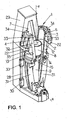
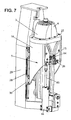
- He is represented on the figure 1 a perspective view of a molding device 1 for the blow-molding or stretch-blow molding of containers from preforms made of heated thermoplastic material.
- the molding device 1 comprises at least one mold 2 comprising at least two half-molds 3, 4 and drive means 5 (not shown in FIG. figure 1 for the sake of clarity but represented on the figures 2 , 3 and 7 ) adapted to move the half-molds 3, 4 between an open position, shown on the figures 1 and 2 , in which they are spaced from each other and a closed position, shown on the figure 3 , in which they are closely joined against each other by respective bearing faces 6, 7 defining a joint plane P and in which they define a molding cavity.
- the two half-molds 3, 4 define in their closed position a molding cavity corresponding to the imprint of the body of the blown blank.
- the two half-molds 3, 4 are articulated to each other in rotation about an axis of articulation XX contained in the joint plane P and perpendicular to the axis of the molding cavity YY, XX axis of articulation being under the two half-molds 3, 4.
- the hinge axis X-X is located below the two half-molds 3, 4 away from them. In other words, the hinge axis XX is located closer to the ground level than are the two half-molds 3, 4. Alternatively, the hinge axis XX can be directly provided through the two half -molds 3, 4.
- the molding device 1 further comprises a base 8 of fixed mold and complementary shape to the two half-molds 3, 4, so that the two half-molds 3, 4 fit into the bottom 8 of the mold in position closure for forming a sealed molding cavity.
- the bottom 8 of the mold is provided fixed on a fixed upright 9 and provided substantially perpendicular to the hinge axis XX. Nevertheless, it is also possible to provide an axially movable mold base 8 adapted to fit into the two half-molds 3, 4 when they are in the closed position (see FIG. figures 5 and 6 ).
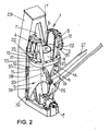
- the drive means comprises a movable member movable in a direction substantially parallel to the axis YY of the molding cavity and cooperating with the two half-molds 3, 4 so that when the moving equipment is in operation lower position, the two half-molds 3, 4 are in the open position and that when the moving equipment 10 is in the high position, the two half-molds 3, 4 are in the closed position.
- the drive means 5 comprises means 11 with follower rollers and cooperating cams provided on the lateral faces 12, 13 of the two half-molds 3, 4 in the vicinity of their respective support faces 6, 7 and on the crew 10. mobile.
- two rollers 14, 15 followers are mounted on two lateral faces 12, 13 respectively belonging to the two half-molds 3, 4 in the vicinity of their faces 6, 7 of FIG. respective support and two cams 19, 20 are provided respectively on the mobile 10.
- two follower rollers are mounted on the moving equipment and two cams are provided formed in the two faces 12, 13 side respectively belonging to the two half-molds 3, 4 in the vicinity of their respective faces 6, 7 of support.
- the molding device 1 has means 21 for locking the two half-molds 3, 4 in their closed position, each half-mold 3, 4 having an outer surface area 22 capable of abutting against an inner surface area 23 of the means 21 for locking the two half-molds 3, 4 in the closed position, the outer surface area 22 of each half-mold 3, 4 being of complementary shape to the inner surface area 23 of the locking means 21, so that, when the two surface areas 22, 23 are brought into contact one against the other, this results in the formation of two forces directed in the opposite direction radially inwards on the two half-molds 3, 4, and preferably towards the YY axis of the molding cavity, so as to implement the bracing principle, as will be described more precisely later.
- the surface areas 22, 23 are substantially frustoconical.
- the locking means 21 are incorporated in the drive means 5, namely that the locking means 21 belong to the moving equipment, which is present in the form of a sleeve 24 adapted to at least partially surround the two half-molds 3, 4.
- the locking means 21 are in any form to maintain contiguous against each other the two half-molds 3, 4, for example using piston-type means.
- the locking means 21 are in the form of a flange 25 belonging to the means 5 for driving the two half-molds 3, 4, that is to say to the mobile equipment 10, and suitable for girding the half-molds 3, 4 in the closed position.
- a roller 26 adapted to cooperate with a cam 27 is fixed on the movable member 10 so as to control the displacement of the movable member 10 in a direction substantially parallel to the Y-Y axis of the molding cavity.
- the mobile unit 10 is able to slide on at least one guide rail 28 provided fixed relative to the axis YY of the molding cavity formed in a support element or console 29 adapted to be secured to a rotating carousel thus allowing the placing a plurality of molding device 1 around the perimeter of the carousel.
- the mobile unit 10 is secured to at least one carriage 30 (preferably two carriages 30) slidable on the guide rail 28.
- Each half-mold 3, 4 comprises a low part 31 fixed to the hinge axis XX and a high part 32 comprising at least one shell holder 33 and a shell 34 in which is formed at least partially the cavity of the container to mold, the locking means 5, preferably the flange 25, of the two half-molds 3, 4 in the closed position are able to bear on the two high parts 32 of the two half-molds 3, 4.
- a stop strip 35 is fixed on the outer surface of the shell holder 33, the outer surface area of the strip 35 being able to abut against the inner surface area 23 of the locking means of the two half -molds 3, 4.
- the molding device 1 comprises biasing means, preferably piston means 44 and as described more specifically later in connection with the invention. figure 7 between the movable member 10 and the element or console 29 supporting the hinge axis XX, whereby the upward movement of the moving member 10 is facilitated from the open position to the position of closing the two half-molds 3, 4.
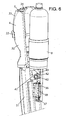
- the figure 4 represents a partial perspective view of a bottom of the mold provided axially movable and secured by securing means, as illustrated in FIG. figure 6 , to a half-mold 4 of the molding device 1 according to the invention.
- a rod 36 from the bottom 8 of the mold preferably substantially coaxial with the axis of the mold cavity, and on which is fixed, by any means known per se, a guide rail 37.
- a holding element 38 in the form of an element H with a first plate 38a fixed on the console 29 and a second plate 38b on which is fixed a carriage 39 adapted to slide on the guide rail 37 of the rod 36 of the mold base 8.
- At least one roller 40 adapted to cooperate with a cam 41 is provided fixed on the rod 36.
- At least one fixed cam 41, 43 is provided, preferably embedded in the half-mold 3, 4, in particular in the lower part 31 of the half-mold 3, 4, with a part of the cam 41, 43 projecting so as to cooperate with the rollers 40, 42.
- the projecting parts of the cams 41, 43 are shaped such that in the closed position of the half-molds 3, 4, the bottom 8 of the mold is in the up position (see FIG. figure 5 ) and that the opening movement of the half-molds 3, 4 causes an axial downward movement of the mold base 8 (see FIG. figure 6 ).
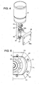
- the figure 7 is a perspective view of the molding device 1 according to the invention in which there is provided a jack 44, the rod 45 of the piston is connected to the mobile 10 and whose body is fixed on the console 29.
- the jack 44 operates between two limit pressures with a high pressure in the low position of the moving equipment, the two half-molds 3, 4 then being in their open position, and a low pressure in the high position of the machine. mobile crew 10, the two half-molds 3, 4 then being in their closed position.
- the lower chamber of the jack 44 is put under a pressure such that the moving equipment tends to undergo a thrust movement on the part of the jack 44 via its rod 45.
- He is represented on the figure 8 an upper view of a half-mold in the closed position and locked by the locking means 21.
- the abutment strip 35 is in tangential contact with the locking means 21 in the high position of the moving equipment 10, that is to say in the closed position of the two half-molds, but only outside the air-blast. the blank, the stop strip 35 being adapted to be pressed against the inner surface 23 of the locking means 21 during the blowing of the blank.
Description
La présente invention concerne d'une façon générale le domaine des dispositifs de moulage pour la fabrication par soufflage ou étirage-soufflage de récipients à partir de préformes en matériau thermoplastique chauffé.The present invention generally relates to the field of molding devices for the blow-molding or stretch-blow molding of containers from preforms of heated thermoplastic material.
De manière générale, l'invention concerne les dispositifs de moulage comportant au moins un moule comprenant au moins deux demi-moules déplaçables mutuellement entre une position d'ouverture dans laquelle ils sont écartés l'un de l'autre et une position de fermeture dans laquelle ils sont étroitement accolés l'un contre l'autre par des faces d'appui respectives définissant un plan de joint.In general, the invention relates to molding devices comprising at least one mold comprising at least two half-molds movable mutually between an open position in which they are spaced from one another and a closed position in which they are closely joined against each other by respective bearing faces defining a joint plane.
Il est principalement connu selon l'art antérieur deux types de dispositifs de moulage pour la fabrication de récipients.It is mainly known according to the prior art two types of molding devices for the manufacture of containers.
Un premier dispositif de moulage porte sur des dispositifs de moulage avec une ouverture du type crocodile, c'est-à-dire avec une moitié du dispositif de moulage qui est fixe sur un carrousel tournant rotatif, une autre moitié amovible pivotante selon un mouvement descendant dirigé radialement vers l'extérieur et un fond de moule axialement amovible. Toutefois, ce dispositif de moulage, du fait de son ouverture de la moitié mobile radialement vers l'extérieur, entraîne un effort centrifuge très pénalisant et nécessite des réglages relativement précis pour le synchronisme avec le mouvement du fond de moule.A first molding device relates to molding devices with a crocodile-type opening, that is to say with one half of the molding device which is fixed on a rotary rotating carousel, another half removable pivotally in a downward movement directed radially outwardly and an axially removable mold bottom. However, this molding device, because of its opening of the movable half radially outward, causes a very penalizing centrifugal force and requires relatively accurate settings for synchronism with the movement of the mold bottom.
Un deuxième type de dispositif de moulage porte sur des dispositifs de moulage du type ouverture en portefeuille, notamment tel que décrit dans le document
De manière pratique, chaque demi-moule comprend un porte-moule auquel est fixée intérieurement une coquille munie d'une demi-empreinte de moulage, le plan de joint étant défini par les deux coquilles accolées en position de fermeture du moule et les moyens de verrouillage sont supportés par les deux porte-moules.Conveniently, each half-mold comprises a mold-holder to which is fixed internally a shell provided with a half-cavity molding, the joint plane being defined by the two shells contiguous in the closed position of the mold and the means of locking are supported by the two mold holders.
De manière alternative et tel que décrit dans le document
Le document
Les dispositifs de moulage connus selon l'art antérieur, bien que satisfaisants du point de vue de la qualité du récipient moulé, présentent certains inconvénients entraînant un frein majeur dans l'augmentation de la cadence de production des récipients moulés par heure à partir de ces dispositifs de moulage.Molding devices known in the prior art, although satisfactory from the point of view of the quality of the molded container, have certain drawbacks leading to a major brake in increasing the rate of production of the containers molded per hour from these molding devices.
Tout d'abord, la chaîne cinématique du transfert du récipient au dispositif de moulage jusqu'au récepteur final du récipient moulé est relativement longue et implique la présence de nombreuses pièces en série.Firstly, the kinematic chain of the transfer of the container to the molding device to the final receiver of the molded container is relatively long and involves the presence of many parts in series.
De plus, la commande de l'ouverture et de la fermeture des moules ainsi que de l'actionnement des moyens de verrouillage du moule nécessitent le réglage de nombreuses pièces susceptibles de présenter des jeux importants.In addition, the control of the opening and closing of the molds and the actuation of the mold locking means require the adjustment of many parts may have significant play.
En effet, de manière courante, la commande des moyens d'ouverture et de fermeture ainsi que la commande des moyens de verrouillage et de déverrouillage des dispositifs de moulage sont réalisées à l'aide d'un premier double ensemble à came et à galet pour la commande de l'ouverture et de la fermeture et d'un second double ensemble à came et à galet respectif pour la commande du verrouillage et du déverrouillage, les deux ensembles étant pilotés indépendamment l'un de l'autre de manière mécanique, ce qui est susceptible de quadrupler les problèmes de réglage et d'entraîner une perte de temps lors de ce réglage. Il serait donc particulièrement intéressant de réaliser un dispositif de moulage dont les opérations d'ouverture et de fermeture ainsi que les opérations de verrouillage et de déverrouillage du dispositif de moulage sont réalisées par une seule commande.Indeed, in a current manner, the control of the opening and closing means as well as the control of the locking and unlocking means of the molding devices are carried out with the aid of a first double cam and roller assembly for control of the opening and closing and a second respective cam and roller assembly for controlling the locking and unlocking, the two assemblies being controlled independently of one another mechanically, this which is likely to quadruple adjustment problems and cause a loss of time during this adjustment. It would therefore be particularly advantageous to make a molding device whose opening and closing operations as well as the locking and unlocking operations of the molding device are performed by a single command.
Par ailleurs, les moyens de verrouillage/déverrouillage des dispositifs de moulage, en général prévus le long d'un bord respectif des demi-moules, occupent un volume d'encombrement susceptible de nuire au transfert du récipient une fois celui-ci moulé.Furthermore, the locking / unlocking means of the molding devices, generally provided along a respective edge of the half-molds, occupy a volume of space likely to affect the transfer of the container once it is molded.
Par ailleurs, les moyens de verrouillage/déverrouillage actuellement utilisés sont souvent associés à des doigts de verrouillage qu'il convient de changer régulièrement du fait de leur usure.Furthermore, the locking / unlocking means currently used are often associated with locking fingers which should be changed regularly because of their wear.
Il serait également particulièrement intéressant de réaliser un dispositif de moulage permettant de faciliter le verrouillage et de déverrouillage des deux demi-moules.It would also be particularly advantageous to provide a molding device for facilitating the locking and unlocking of the two half-molds.
Afin d'améliorer la qualité du récipient moulé, notamment en terme de lisibilité du plan de joint, il est nécessaire de prévoir une chambre de compensation à l'intérieur du moule dont le mode de fonctionnement est synchronisé avec les moyens de verrouillage et de déverrouillage, ce qui entraîne des difficultés de réglage supplémentaires.In order to improve the quality of the molded container, particularly in terms of legibility of the joint plane, it is necessary to provide a chamber of compensation inside the mold whose operating mode is synchronized with the locking and unlocking means, which causes additional adjustment difficulties.
En effet, dans les dispositifs de moulage du type à portefeuille, il est prévu, en coopération avec un demi-moule, une chambre de compensation de pression afin de garantir l'étanchéité à l'intérieur du moule. De manière plus précise, le document
Toutefois, la chambre de compensation ne permet pas de compenser des bouteilles supérieures à 1,5 litre. De plus, du fait que la chambre de compensation n'est présente que sur un demi-moule, il est possible d'avoir un décalage des plans de joints dû à l'inhomogénéité des rigidités entre les deux demi-moules.However, the clearing house does not compensate for bottles larger than 1.5 liters. In addition, because the compensation chamber is only present on a half-mold, it is possible to have a shift of the joint planes due to the inhomogeneity of the rigidities between the two half-molds.
De même, la présence de cette chambre de compensation est relativement complexe à mettre en forme et à réaliser. Il serait donc particulièrement intéressant de réaliser un dispositif de moulage ne nécessitant pas la présence d'une chambre de compensation entre le support de moule et le bloc de moule d'un demi-moule.Similarly, the presence of this clearing house is relatively complex to form and achieve. It would therefore be particularly advantageous to provide a molding device that does not require the presence of a compensation chamber between the mold support and the mold block of a half-mold.
Par ailleurs, le rendement thermique des dispositifs de moulage selon l'art antérieur est diminué du fait de la présence de nombreux échanges de flux thermiques entre les au moins deux demi-moules et le fond de moule, ce rendement étant d'autant plus diminué en configuration de soufflage HR (Heat resistant) puisque dans ce cas le fond de moule est refroidi et que les au moins deux demi-moules sont réchauffés.Moreover, the thermal efficiency of the molding devices according to the prior art is reduced because of the presence of numerous exchanges of heat flows between the at least two half-molds and the mold bottom, this yield being all the more diminished. in HR (heat resistant) blow molding configuration since in this case the mold bottom is cooled and the at least two half-molds are heated.
Les dispositifs de moulage tels qu'actuellement réalisés ne peuvent atteindre qu'une cadence maximum de 1800 bouteilles par heure et par dispositif de moulage, du fait de la présence de nombreuses erreurs dynamiques, notamment des problèmes vibratoires et de déformation des systèmes de commande à came et à galet, ainsi que des problèmes de charge et d'usure des dispositifs de moulage.Molding devices such as currently achieved can achieve a maximum rate of 1800 bottles per hour and per molding device, due to the presence of numerous dynamic errors, including vibration problems and deformation of the control systems. cam and roller, as well as problems of load and wear of the molding devices.
La tolérance des réglages est de plus également très faible, c'est-à-dire de l'ordre du dixième de millimètre. Il serait donc particulièrement intéressant de réaliser un dispositif de moulage avec des tolérances de réglage plus grandes.The tolerance of the settings is also very low, that is to say of the order of a tenth of a millimeter. It would therefore be particularly advantageous to make a molding device with greater adjustment tolerances.
La hauteur totale de la chambre de compensation est également limitée, ainsi que les réglages délicats.The total height of the clearing room is also limited, as are the delicate settings.
De plus, la connectique fluidique est parfois problématique du fait d'un encombrement relativement important du dispositif de moulage.In addition, the fluidic connection is sometimes problematic because of a relatively large size of the molding device.
Il est connu du document
Il serait donc particulièrement intéressant de réaliser un dispositif de moulage permettant notamment : d'améliorer la chaîne cinématique; d'améliorer la qualité du récipient moulé, c'est-à-dire d'obtenir un récipient dont les plans de joints ne sont pas ou à peine visibles ; d'améliorer le rendement thermique du dispositif de moulage, à savoir de diminuer les pertes de chaleur ; d'augmenter les cadences mécaniques, c'est-à-dire d'aller au-delà d'une cadence de production de 1800 bouteilles par heure et par dispositif de moulage ; d'améliorer les tolérances de réglage de ce dispositif ; de diminuer les connections fluidiques entre le dispositif de moulage ; de minimiser les coûts de production ; de pouvoir utiliser des matériaux plus légers et mieux adaptés pour tout poste de soufflage ; de garantir un verrouillage des demi-moules au moment du soufflage de la préforme, ainsi que de robotiser les changements des différentes pièces du moule, à savoir les changements de coquilles ou des éléments de moule dans lesquels sont formés les empreintes du récipient devant être soufflé.It would therefore be particularly advantageous to produce a molding device that makes it possible in particular: to improve the kinematic chain; to improve the quality of the molded container, that is to say to obtain a container whose joint planes are not or barely visible; to improve the thermal efficiency of the molding device, namely to reduce heat loss; to increase the mechanical rates, that is to say to go beyond a production rate of 1800 bottles per hour and per molding device; to improve the adjustment tolerances of this device; to reduce the fluidic connections between the molding device; to minimize production costs; to be able to use lighter and better suited materials for any blowing station; to guarantee a locking of the half-molds at the time of blowing of the preform, as well as to robotize the changes of the various parts of the mold, namely the changes of shells or mold elements in which are formed the imprints of the container to be blown .
Afin de répondre à ces différents éléments, la présente invention porte sur un dispositif de moulage pour la fabrication par soufflage ou étirage-soufflage de récipients à partir de préformes en matériau thermoplastique chauffé, ledit dispositif comportant au moins un moule comprenant au moins deux demi-moules et des moyens d'entraînement propres à déplacer les demi-moules entre une position d'ouverture dans laquelle ils sont écartés l'un de l'autre et une position de fermeture dans laquelle ils sont étroitement accolés l'un contre l'autre par des faces d'appui respectives définissant un plan de joint et dans laquelle ils définissent une cavité de moulage, les deux demi-moules étant articulés l'un à l'autre en rotation autour d'un axe d'articulation contenu dans le plan de joint et perpendiculaire à l'axe de la cavité de moulage, ledit axe d'articulation étant sous les deux demi-moules, des moyens de verrouillage des deux demi-moules dans leur position de fermeture étant également prévus, chaque demi-moule présentant une zone surfacique extérieure apte à venir en butée contre une zone surfacique intérieure de moyens de verrouillage des deux demi-moules en position de fermeture, la zone surfacique extérieure de chaque demi-moule étant de forme complémentaire à la zone surfacique intérieure des moyens de verrouillage, de manière que, quand les deux zones surfaciques sont mises en contact l'une contre l'autre, il en résulte la formation de deux efforts dirigés en sens inverse radialement vers l'intérieur sur les deux demi-moules et lesdits moyens de verrouillage se présentant sous la forme d'une bride propre à ceindre les deux demi-moules en position de fermeture, caractérisé en ce que les moyens d'entraînement comprennent un équipage mobile, se présentant sous la forme d'un manchon propre à entourer au moins partiellement les deux demi-moules, déplaçable selon une direction sensiblement parallèle à l'axe de la cavité de moulage et coopérant avec les deux demi-moules de manière que, lorsque l'équipage mobile est en position basse, les deux demi-moules sont en position d'ouverture et que, lorsque l'équipage mobile est en position haute, les deux demi-moules sont en position de fermeture, et en ce que ladite bride appartient auxdits moyens d'entraînement des deux demi-moules.In order to respond to these different elements, the present invention relates to a molding device for the blow-molding or stretch-blow molding of containers from preforms made of heated thermoplastic material, said device comprising at least one mold comprising at least two semi-molds. molds and drive means adapted to move the half-molds between an open position in which they are spaced from each other and a closed position in which they are closely coupled against each other by respective bearing faces defining a joint plane and in which they define a molding cavity, the two half-molds being articulated to one another in rotation about a hinge axis contained in the plane joint and perpendicular to the axis of the molding cavity, said hinge pin being under the two half-molds, locking means of the two half-molds in their position of fe rmeture being also provided, each half-mold having an outer surface area adapted to abut against an inner surface area of locking means of the two half-molds in the closed position, the outer surface area of each half-mold being complementary in shape to the inner surface area of the locking means, so that when the two surface areas are brought into contact with each other, this results in the formation of two counter-radially inward-facing forces on the two half-molds and the said locking means being in the form of a flange adapted to encase the two half-molds in the closed position, characterized in that the drive means comprise a moving element, in the form of a sleeve adapted to at least partially surround the two half-molds, displaceable in a direction substantially parallel to the axis of the molding cavity, and cooperating with the two half-molds so that, when the moving equipment is in the down position, the two half-molds are in the open position and when the mobile crew the is in the high position, the two half-molds are in the closed position, and in that said flange belongs to said drive means of the two half-molds.
Avantageusement, les zones surfaciques sont sensiblement tronconiques.Advantageously, the surface areas are substantially frustoconical.
Selon une forme de réalisation avantageuse, l'axe d'articulation est situé en dessous des deux demi-moules à distance de ceux-ci.According to an advantageous embodiment, the axis of articulation is located below the two half-molds at a distance from them.
De manière avantageuse, les moyens d'entraînement comprennent des moyens à galets suiveurs et cames coopérants prévus sur les faces latérales des deux demi-moules au voisinage de leurs faces d'appui respectives et sur l'équipage mobile.Advantageously, the drive means comprise follower and cooperating cam follower means provided on the lateral faces of the two half-molds in the vicinity of their respective bearing faces and on the moving equipment.
Selon une première forme de réalisation des moyens à galets suiveurs et cames, deux galets suiveurs sont montés sur deux faces latérales appartenant respectivement aux deux demi-moules au voisinage de leurs faces d'appui respectives et deux cames sont prévues respectivement sur l'équipage mobile.According to a first embodiment of the follower and cam follower means, two follower rollers are mounted on two lateral faces respectively belonging to the two half-molds in the vicinity of their respective bearing faces and two cams are respectively provided on the moving element. .
Selon une seconde forme de réalisation des moyens à galets suiveurs et cames, deux galets suiveurs sont montés sur l'équipage mobile et deux cames sont prévues sur deux faces latérales appartenant respectivement aux deux demi-moules au voisinage de leurs faces d'appui respectives.According to a second embodiment of the follower and cam follower means, two follower rollers are mounted on the moving element and two cams are provided on two lateral faces respectively belonging to the two half-molds in the vicinity of their respective bearing faces.
Afin de limiter l'usure entre les deux zones surfaciques, les zones surfaciques sont sensiblement tronconiques.In order to limit the wear between the two surface zones, the surface zones are substantially frustoconical.
Afin de commander le déplacement de l'équipage mobile selon une direction sensiblement parallèle à l'axe de la cavité de moulage, un galet propre à coopérer avec une came est fixé sur l'équipage mobile.In order to control the displacement of the moving element in a direction substantially parallel to the axis of the molding cavity, a roller adapted to cooperate with a cam is fixed on the moving element.
De manière avantageuse, l'équipage mobile est apte à coulisser sur au moins un rail de guidage prévu fixe par rapport à l'axe d'articulation.Advantageously, the mobile assembly is able to slide on at least one guide rail provided fixed relative to the hinge axis.
De manière préférentielle, le rail de guidage est prévu sur un élément support de l'axe d'articulation des deux demi-moules.Preferably, the guide rail is provided on a support member of the hinge axis of the two half-molds.
Selon une forme de réalisation, l'équipage mobile est solidarisé à au moins un chariot apte à coulisser sur le rail de guidage.According to one embodiment, the moving element is secured to at least one carriage slidable on the guide rail.
Afin de faciliter le déplacement de l'équipage mobile depuis la position d'ouverture vers la position de fermeture des deux demi-moules, le dispositif de moulage selon l'invention comprend des moyens de rappel, préférentiellement des moyens à piston, entre l'équipage mobile et un élément support de l'axe d'articulation.In order to facilitate the movement of the moving equipment from the open position to the closed position of the two half-molds, the molding device according to the invention comprises biasing means, preferably piston means, between the movable element and a support element of the articulation axis.
Afin de faciliter la maintenance des différentes pièces constitutives des deux demi-moules, chaque demi-moule comprend une partie basse fixée à l'axe d'articulation et une partie haute comprenant au moins un porte-coquille et une coquille dans laquelle est formée au moins partiellement l'empreinte du récipient à mouler.In order to facilitate the maintenance of the various constituent parts of the two half-molds, each half-mold comprises a lower part fixed to the hinge axis and an upper part comprising at least one shell holder and a shell in which is formed less partially the impression of the container to be molded.
Avantageusement, les moyens de verrouillage des deux demi-moules en position de fermeture sont aptes à prendre appui sur les parties hautes des deux demi-moules.Advantageously, the locking means of the two half-molds in the closed position are able to bear on the upper parts of the two half-molds.
Afin de remplacer facilement les moyens de verrouillage, un ruban de butée est fixé sur la surface extérieure du porte-coquille, la zone surfacique extérieure du ruban étant apte à venir en butée contre la zone surfacique intérieure des moyens de verrouillage des deux demi-moules.In order to easily replace the locking means, a stop strip is fixed on the outer surface of the shell holder, the outer surface area of the strip being adapted to abut against the inner surface area of the locking means of the two half-molds .
Afin de diminuer le temps de transfert d'une ébauche soufflée et d'éviter de devoir remonter l'ébauche une fois celle-ci soufflée, le dispositif de moulage comprend un fond de moule axialement mobile et couplé à l'aide de moyens de solidarisation à un des deux demi-moules.In order to reduce the transfer time of a blown blank and to avoid having to go up the blank once blown, the molding device comprises an axially movable mold bottom and coupled by means of securing means to one of the two half-molds.
De manière à synchroniser le mouvement de coulissement axial du fond de moule avec le mouvement d'ouverture/fermeture des demi-moules, les moyens de solidarisation comprennent au moins un galet, solidarisé au fond de moule, propre à coopérer avec au moins une came fixée sur un des deux demi-moules, de sorte que le fond de moule soit dans une position haute quand les deux demi-moules sont dans leur position de fermeture et que le fond de moule soit dans une position basse quand les deux demi-moules sont dans leur position d'ouverture.In order to synchronize the axial sliding movement of the mold base with the opening / closing movement of the half-molds, the securing means comprise at least one roller, secured to the mold base, adapted to cooperate with at least one cam fixed on one of the two half-molds, so that the mold bottom is in a high position when the two half-molds are in their closed position and the mold bottom is in a low position when the two half-molds are in their open position.
Afin de permettre une légère déformation et un meilleur blocage des demi-moules lors de l'opération de soufflage de l'ébauche, le ruban de butée est en contact tangentiel avec les moyens de verrouillage en position haute de l'équipage mobile en dehors du soufflage de l'ébauche.In order to allow a slight deformation and a better locking of the half-molds during the roughing operation of the blank, the stop strip is in tangential contact with the locking means in the high position of the moving element outside the blowing of the blank.
De manière avantageuse, le ruban de butée est propre à être plaqué contre la surface intérieure des moyens de verrouillage lors du soufflage de l'ébauche.Advantageously, the stop strip is adapted to be pressed against the inner surface of the locking means during the blowing of the blank.
La présente invention est maintenant décrite à l'aide d'un exemple uniquement illustratif et nullement limitatif de la portée de la présente invention, et à partir des figures suivantes dans lesquelles :
- La
figure 1 est une vue en perspective du dispositif de moulage selon l'invention dans la position d'ouverture des deux demi-moules, le moyen d'entraînement des deux demi-moules n'étant pas représenté par mesure de clarté ; - La
figure 2 est une vue en perspective du dispositif de moulage selon l'invention dans sa position d'ouverture ; - La
figure 3 est une vue en perspective du dispositif de moulage selon l'invention dans sa position de fermeture ; - La
figure 4 est une vue en perspective d'une forme de réalisation d'un fond de moule axialement mobile apte à être intégré au dispositif de moulage selon l'invention ; - La
figure 5 est une vue partielle en perspective des moyens de solidarisation entre le fond de moule illustré à lafigure 4 et un demi-moule du dispositif selon l'invention, en position de fermeture pour soufflage ; - La
figure 6 est une vue partielle en perspective des moyens de solidarisation entre le fond de moule illustré à lafigure 4 et un demi-moule du dispositif selon l'invention, en position d'ouverture pour transfert de l'ébauche soufflée ; - La
figure 7 est une vue en perspective d'une forme de réalisation particulière du dispositif de moulage selon l'invention ; - La
figure 8 est une vue supérieure d'un demi-moule en position de fermeture et verrouillé par des moyens de verrouillage.
- The
figure 1 is a perspective view of the molding device according to the invention in the open position of the two half-molds, the drive means of the two half-molds not being represented for the sake of clarity; - The
figure 2 is a perspective view of the molding device according to the invention in its open position; - The
figure 3 is a perspective view of the molding device according to the invention in its closed position; - The
figure 4 is a perspective view of an embodiment of an axially movable mold bottom adapted to be integrated in the molding device according to the invention; - The
figure 5 is a partial perspective view of the securing means between the mold bottom illustrated in FIG.figure 4 and a half-mold of the device according to the invention, in the closed position for blowing; - The
figure 6 is a partial perspective view of the securing means between the mold bottom illustrated in FIG.figure 4 and a half-mold of the device according to the invention, in the open position for transferring the blown blank; - The
figure 7 is a perspective view of a particular embodiment of the molding device according to the invention; - The
figure 8 is an upper view of a half-mold in the closed position and locked by locking means.
Il est représenté sur la
Dans la suite de la description, il sera utilisé les termes de vertical, horizontal, haut, bas, etc...en référence aux dessins qui illustrent une disposition largement répandue d'un dispositif de moulage. Cependant, ces termes ne sont utilisés que pour la clarté de la description et ne doivent pas être interprétés comme étant des limitations à l'invention.In the remainder of the description, the terms vertical, horizontal, high, low, etc. will be used with reference to the drawings which illustrate a widespread provision of a molding device. However, these terms are used only for clarity of description and should not be construed as limitations to the invention.
Le dispositif 1 de moulage comporte au moins un moule 2 comprenant au moins deux demi-moules 3, 4 et des moyens d'entraînement 5 (non représentés sur la
Plus précisément, les deux demi-moules 3, 4 définissent dans leur position de fermeture une cavité de moulage correspondant à l'empreinte du corps de l'ébauche soufflée.More specifically, the two half-
Les deux demi-moules 3, 4 sont articulés l'un à l'autre en rotation autour d'un axe d'articulation X-X contenu dans le plan de joint P et perpendiculaire à l'axe de la cavité de moulage Y-Y, l'axe d'articulation X-X étant sous les deux demi-moules 3, 4.The two half-
Il est entendu par « axe de la cavité de moulage » l'axe de soufflage de la tuyère de soufflage.It is understood by "axis of the molding cavity" the blowing axis of the blowing nozzle.
L'axe d'articulation X-X est situé en dessous des deux demi-moules 3, 4 à distance de ceux-ci. Autrement dit, l'axe d'articulation X-X est situé plus près du niveau du sol que ne le sont les deux demi-moules 3, 4. De manière alternative, l'axe d'articulation X-X peut être directement prévu traversant les deux demi-moules 3, 4.The hinge axis X-X is located below the two half-
Le dispositif 1 de moulage comporte en outre un fond 8 de moule fixe et de forme complémentaire aux deux demi-moules 3, 4, de manière que les deux demi-moules 3, 4 s'emboîtent dans le fond 8 de moule en position de fermeture permettant de former une cavité de moulage étanche.The molding device 1 further comprises a
Préférentiellement, le fond 8 de moule est prévu fixé sur un montant 9 fixe et prévu sensiblement perpendiculairement à l'axe d'articulation X-X. Néanmoins, il est également possible de prévoir un fond 8 de moule axialement mobile propre à s'emboîter dans les deux demi-moules 3, 4 quand ils sont en position de fermeture (voir
Les moyens 5 d'entraînement comprennent un équipage 10 mobile déplaçable selon une direction sensiblement parallèle à l'axe Y-Y de la cavité de moulage et coopérant avec les deux demi-moules 3, 4 de manière que, lorsque l'équipage 10 mobile est en position basse, les deux demi-moules 3, 4 sont en position d'ouverture et que, lorsque l'équipage 10 mobile est en position haute, les deux demi-moules 3, 4 sont en position de fermeture.The drive means comprises a movable member movable in a direction substantially parallel to the axis YY of the molding cavity and cooperating with the two half-
Les moyens 5 d'entraînement comprennent des moyens 11 à galets suiveurs et cames coopérants prévus sur les faces 12, 13 latérales des deux demi-moules 3, 4 au voisinage de leurs faces 6, 7 d'appui respectives et sur l'équipage 10 mobile.The drive means 5 comprises means 11 with follower rollers and cooperating cams provided on the lateral faces 12, 13 of the two half-
Selon une première forme de réalisation et telle qu'illustrée sur les figures, deux galets 14, 15 suiveurs sont montés sur deux faces 12, 13 latérales appartenant respectivement aux deux demi-moules 3, 4 au voisinage de leurs faces 6, 7 d'appui respectives et deux cames 19, 20 sont prévues respectivement sur l'équipage 10 mobile.According to a first embodiment and as illustrated in the figures, two
Selon une seconde forme de réalisation (non représentée sur les figures) et de manière inversée par rapport à la première forme de réalisation, deux galets suiveurs sont montés sur l'équipage 10 mobile et deux cames sont prévues formées dans les deux faces 12, 13 latérales appartenant respectivement aux deux demi-moules 3, 4 au voisinage de leurs faces 6, 7 d'appui respectives.According to a second embodiment (not shown in the figures) and inverted with respect to the first embodiment, two follower rollers are mounted on the moving equipment and two cams are provided formed in the two faces 12, 13 side respectively belonging to the two half-
Le dispositif 1 de moulage présente des moyens 21 de verrouillage des deux demi-moules 3, 4 dans leur position de fermeture, chaque demi-moule 3, 4 présentant une zone 22 surfacique extérieure apte à venir en butée contre une zone 23 surfacique intérieure des moyens 21 de verrouillage des deux demi-moules 3, 4 en position de fermeture, la zone 22 surfacique extérieure de chaque demi-moule 3, 4 étant de forme complémentaire à la zone 23 surfacique intérieure des moyens 21 de verrouillage, de manière que, quand les deux zones 22, 23 surfaciques sont mises en contact l'une contre l'autre, il en résulte la formation de deux efforts dirigés en sens inverse radialement vers l'intérieur sur les deux demi-moules 3, 4, et préférentiellement vers l'axe Y-Y de la cavité de moulage, de façon à mettre en oeuvre le principe d'arc-boutement, tel qu'il sera décrit de manière plus précise ultérieurement.The molding device 1 has means 21 for locking the two half-
Selon une forme de réalisation, les zones 22, 23 surfaciques sont sensiblement tronconiques.According to one embodiment, the
Selon le mode de réalisation illustré sur les figures, les moyens 21 de verrouillage sont incorporés dans les moyens 5 d'entraînement, à savoir que les moyens 21 de verrouillage appartiennent à l'équipage 10 mobile, qui se présente sous la forme d'un manchon 24 propre à entourer au moins partiellement les deux demi-moules 3, 4. Toutefois, de manière alternative, il est possible de prévoir que les moyens 21 de verrouillage se présentent sous toute forme permettant de maintenir accolés l'un contre l'autre les deux demi-moules 3, 4, par exemple à l'aide de moyens de type piston.According to the embodiment illustrated in the figures, the locking means 21 are incorporated in the drive means 5, namely that the locking means 21 belong to the moving equipment, which is present in the form of a
Les moyens 21 de verrouillage se présentent sous la forme d'une bride 25 appartenant aux moyens 5 d'entraînement des deux demi-moules 3, 4, c'est-à-dire à l'équipage 10 mobile, et propres à ceindre les demi-moules 3, 4 en position de fermeture.The locking means 21 are in the form of a
Un galet 26 propre à coopérer avec une came 27 est fixé sur l'équipage 10 mobile de manière à commander le déplacement de l'équipage 10 mobile selon une direction sensiblement parallèle à l'axe Y-Y de la cavité de moulage.A
Ainsi, il est représenté sur la
L'équipage 10 mobile est apte à coulisser sur au moins un rail 28 de guidage prévu fixe par rapport à l'axe Y-Y de la cavité de moulage formé dans un élément support ou console 29 apte à être solidarisé à un carrousel rotatif permettant ainsi le placement d'une pluralité de dispositif 1 de moulage sur le pourtour du carrousel.The
Préférentiellement, l'équipage 10 mobile est solidarisé à au moins un chariot 30 (préférentiellement deux chariots 30) apte à coulisser sur le rail 28 de guidage.Preferably, the
Chaque demi-moule 3, 4 comprend une partie 31 basse fixée à l'axe X-X d'articulation et une partie 32 haute comprenant au moins un porte-coquille 33 et une coquille 34 dans laquelle est formée au moins partiellement l'empreinte du récipient à mouler, les moyens 5 de verrouillage, préférentiellement la bride 25, des deux demi-moules 3, 4 en position de fermeture sont aptes à prendre appui sur les deux parties 32 hautes des deux demi-moules 3, 4.Each half-
Selon un mode de réalisation, un ruban 35 de butée est fixé sur la surface extérieure du porte-coquille 33, la zone surfacique extérieure du ruban 35 étant apte à venir en butée contre la zone surfacique 23 intérieure des moyens 5 de verrouillage des deux demi-moules 3, 4.According to one embodiment, a
Le dispositif 1 de moulage selon l'invention comprend des moyens de rappel, préférentiellement des moyens 44 à piston et tels que décrits plus précisément ultérieurement en rapport avec la
La
De manière plus précise, il est prévu une tige 36 partant du fond 8 de moule, préférentiellement sensiblement coaxiale à l'axe de la cavité de moulage, et sur laquelle est fixé, par tout moyen connu en soi, un rail 37 de guidage.More specifically, there is provided a
Sur la console 29 est fixé un élément 38 de maintien sous la forme d'un élément en H avec une première plaque 38a fixée sur la console 29 et une seconde plaque 38b sur laquelle est fixé un chariot 39 apte à coulisser sur le rail 37 de guidage de la tige 36 du fond de moule 8.On the
Au moins un galet 40 propre à coopérer avec une came 41 est prévu fixé sur la tige 36. Préférentiellement il est prévu deux galets 40, 42 coopérant chacun avec une came 41, 43.At least one
Dans un des deux demi-moules 3, 4, il est prévu au moins une came 41, 43 fixe, préférentiellement encastrée dans le demi-moule 3, 4, notamment dans la partie basse 31 du demi-moule 3, 4, avec une partie de la came 41, 43 en saillie de sorte à coopérer avec les galets 40, 42.In one of the two half-
Les parties en saillie des cames 41, 43 sont conformées de manière telle qu'en position de fermeture des demi-moules 3, 4, le fond 8 de moule est en position haute (voir
La
Préférentiellement, le vérin 44 travaille entre deux pressions limites avec une pression élevée en position basse de l'équipage 10 mobile, les deux demi-moules 3, 4 étant alors dans leur position d'ouverture, et une pression faible en position haute de l'équipage 10 mobile, les deux demi-moules 3, 4 étant alors dans leur position de fermeture.Preferably, the
Plus précisément, la chambre basse du vérin 44 est mise à une pression telle que l'équipage 10 mobile a tendance à subir un mouvement de poussée de la part du vérin 44 par l'intermédiaire de sa tige 45.More specifically, the lower chamber of the
De cette manière, le mouvement de remontée de l'équipage 10 mobile lors de son passage de la position basse à la position haute est facilitée, malgré la masse de l'équipage 10 mobile.In this way, the upward movement of the moving crew during its passage from the low position to the high position is facilitated, despite the mass of the moving crew.
Il est bien entendu qu'il est possible de prévoir plus d'un seul vérin entre l'équipage 10 mobile et la console 29, ou de prévoir des moyens ressort.It is understood that it is possible to provide more than one cylinder between the mobile and the
Il est représenté sur la
Comme cela peut être remarqué que la
Claims (18)
- Moulding device (1) for blow-moulding or stretch-blow-moulding containers from heated thermoplastic preforms, said device (1) having at least one mould (2) comprising at least two half-moulds (3, 4) and drive means (5) that are able to move said half-moulds (3, 4) between an open position in which they are parted from one another and a closed position in which they are firmly pressed against one another via respective bearing faces (6, 7) defining a parting plane (P) and in which they define a mould cavity, the two half-moulds (3, 4) being articulated together in rotation about an articulation axis (X-X) that is contained in the parting plane (P) and perpendicular to the axis (Y-Y) of the mould cavity, said articulation axis (X-X) being beneath the two half-moulds (3, 4), means (21) for locking the two half-moulds (3, 4) in their closed position also being provided, each half-mould (3, 4) having an external surface region (22) that is able to come into abutment against an internal surface region (23) of said means (21) for locking the two half-moulds (3, 4) in the closed position, the external surface region (22) of each half-mould (3, 4) having a shape complementary to the internal surface region (23) of the locking means (21), such that, when the two surface regions (22, 23) are brought into contact with one another, this results in the formation of two forces directed in opposite directions radially towards the inside on the two half-moulds (3, 4), and said locking means (21) being in the form of a flange (25) that is able to encircle the two half-moulds (3, 4) in the closed position,
characterized in that the drive means (5) comprise a mobile assembly (10), in the form of a sleeve (24) that is able to at least partially surround the two half-moulds (3, 4), said mobile assembly (10) being movable in a direction approximately parallel to the axis (Y-Y) of the mould cavity and cooperating with the two half-moulds (3, 4) such that when the mobile assembly (10) is in a bottom position, the two half-moulds (3, 4) are in the open position, and when the mobile assembly (10) is in a top position, the two half-moulds (3, 4) are in the closed position, and in that said flange (25) belongs to said drive means (5) for the two half-moulds (3, 4). - Moulding device according to the preceding Claim 1, characterized in that the surface regions (22, 23) are approximately frustoconical.
- Moulding device according to Claim 1 or 2, characterized in that the articulation axis (X-X) is located beneath the two half-moulds (3, 4) and at a distance therefrom.
- Moulding device according to any one of Claims 1 to 3, characterized in that the drive means (5) comprise cooperating cam and follower roller means (11) provided on the lateral faces (12, 13) of the two half-moulds (3, 4) in the vicinity of their respective bearing faces (6, 7) and on the mobile assembly (10).
- Moulding device according to Claim 4, characterized in that the drive means (5) comprise two follower rollers (14, 15) mounted on two lateral faces (12, 13) that belong respectively to the two half-moulds (3, 4) in the vicinity of their respective bearing faces (6, 7), and two cams (19, 20) provided respectively on the mobile assembly (10).
- Moulding device according to Claim 4, characterized in that the drive means (5) comprise two follower rollers mounted on the mobile assembly (10), and two cams provided on two lateral faces (12, 13) that belong respectively to the two half-moulds (3, 4) in the vicinity of their respective bearing faces (6, 7).
- Moulding device according to any one of Claims 1 to 6, characterized in that the drive means (5) comprise a roller (26) which is able to cooperate with a cam (27) and which is fixed to the mobile assembly (10) so as to control said movement of the mobile assembly (10) in a direction approximately parallel to the axis (Y-Y) of the mould cavity.
- Moulding device according to any one of Claims 1 to 7, characterized in that the drive means (5) comprise at least one guide rail (28) which is provided in a fixed manner with respect to the articulation axis (X-X) and on which the mobile assembly (10) is able to slide.
- Moulding device according to Claim 8, characterized in that the guide rail (28) is provided on a support element (29) of the articulation axis (X-X) of the two half-moulds (3, 4).
- Moulding device according to Claim 9, characterized in that the drive means (5) comprise at least one carriage (30) which is able to slide on the guide rail (28) and to which the mobile assembly (10) is secured.
- Moulding device according to any one of Claims 1 to 10, characterized in that it comprises return means, preferably piston means (44), between the mobile assembly (10) and a support element (29) of the articulation axis (X-X), thereby making it easier to move the mobile assembly (10) from the open position to the closed position of the two half-moulds (3, 4).
- Moulding device according to any one of Claims 1 to 11, characterized in that each half-mould (3, 4) comprises a bottom part (31) fixed at the articulation axis (X-X) and a top part (32) comprising at least one shell holder (33) and a shell (34) in which the impression of the container to be moulded is at least partially formed.
- Moulding device according to Claim 12, characterized in that the means (21) for locking the two half-moulds (3, 4) in the closed position are able to bear against the top parts (32) of the two half-moulds (3, 4).
- Moulding device according to either one of Claims 12 and 13, characterized in that a stop strip (35) is fixed to the external surface of the shell holder (33), the external surface region of the strip (35) being able to bear against the internal surface region (23) of the means (21) for locking the two half-moulds (3, 4).
- Moulding device according to any one of Claims 1 to 14, also comprising a mould bottom (8), characterized in that the mould bottom (8) is axially mobile and is coupled to one of the two half-moulds (3, 4) with the aid of securing means.
- Moulding device according to Claim 15, characterized in that the securing means comprise at least one roller (40, 42) which is secured to the mould bottom (8) and which is able to cooperate with at least one cam (41, 43) fixed to one of the two half-moulds (3, 4), such that the mould bottom (8) is in a top position when the two half-moulds are in their closed position and the mould bottom (8) is in a bottom position when the two half-moulds are in their open position.
- Moulding device according to either one of Claims 15 and 16, characterized in that the stop strip (35) is intangential contact with the locking means (21) in the top position of the mobile assembly (10) when the blank is not being blow-moulded.
- Moulding device according to any one of Claims 15 to 17, characterized in that the stop strip (35) is able to be pressed against the internal surface (23) of the locking means (21) when the blank is being blow-moulded.
Applications Claiming Priority (2)
| Application Number | Priority Date | Filing Date | Title |
|---|---|---|---|
| FR0701396A FR2912952B1 (en) | 2007-02-27 | 2007-02-27 | MOLDING DEVICE FOR MANUFACTURING CONTAINERS OF THERMOPLASTIC MATERIAL |
| PCT/FR2008/050274 WO2008113932A2 (en) | 2007-02-27 | 2008-02-19 | Moulding device for making vessels of a thermoplastic material |
Publications (2)
| Publication Number | Publication Date |
|---|---|
| EP2125331A2 EP2125331A2 (en) | 2009-12-02 |
| EP2125331B1 true EP2125331B1 (en) | 2015-07-22 |
Family
ID=38567045
Family Applications (1)
| Application Number | Title | Priority Date | Filing Date |
|---|---|---|---|
| EP08762122.3A Not-in-force EP2125331B1 (en) | 2007-02-27 | 2008-02-19 | Moulding device for making vessels of a thermoplastic material |
Country Status (7)
| Country | Link |
|---|---|
| US (1) | US8215948B2 (en) |
| EP (1) | EP2125331B1 (en) |
| JP (1) | JP5028498B2 (en) |
| CN (1) | CN101663151B (en) |
| FR (1) | FR2912952B1 (en) |
| MX (1) | MX2009009102A (en) |
| WO (1) | WO2008113932A2 (en) |
Families Citing this family (7)
| Publication number | Priority date | Publication date | Assignee | Title |
|---|---|---|---|---|
| FR2926035B1 (en) | 2008-01-09 | 2017-02-03 | Sidel Participations | MOLD BOTTOM FOR MOLD FOR MANUFACTURING THERMOPLASTIC CONTAINERS, AND MOLDING DEVICE EQUIPPED WITH AT LEAST ONE MOLD PROVIDED WITH SUCH A BOTTOM |
| FR2945979A1 (en) | 2009-05-29 | 2010-12-03 | Sidel Participations | MOLDING DEVICE WITH FLUID CIRCUIT (S) |
| DE102010039802A1 (en) | 2010-08-26 | 2012-03-01 | Krones Aktiengesellschaft | blow |
| DE102010040004A1 (en) | 2010-08-31 | 2012-03-01 | Krones Aktiengesellschaft | blow |
| FR2972386B1 (en) | 2011-03-08 | 2014-10-10 | Sidel Participations | ASSEMBLY ASSEMBLY SYSTEM FOR MOLDING UNIT MOLDING MACHINE FOR CONTAINER MANUFACTURING MACHINE |
| DE102011104316A1 (en) * | 2011-06-03 | 2012-12-06 | Krones Aktiengesellschaft | Device and system for insert blowing plastic preforms and use of a ceramic component |
| DE202013009941U1 (en) | 2012-11-12 | 2013-11-20 | Khs Corpoplast Gmbh | Apparatus for blow-molding containers with a drive device and coupled motion sequences |
Family Cites Families (16)
| Publication number | Priority date | Publication date | Assignee | Title |
|---|---|---|---|---|
| GB763583A (en) * | 1951-12-17 | 1956-12-12 | Francis Trigg Parfrey | A new and improved method of and means for forming hollow articles from thermoplastic material by blowing |
| BE642610A (en) * | 1959-07-02 | |||
| US3344475A (en) * | 1965-11-08 | 1967-10-03 | Salvatore M Gioe | Apparatus for shaping materials and substances into a round ball |
| DE1943874A1 (en) * | 1969-08-29 | 1971-03-11 | Fischer Rainer | Device for producing hollow bodies from thermoplastic material |
| US3881855A (en) * | 1973-01-16 | 1975-05-06 | Francis Farkas | Injection blow molding apparatus |
| CA987463A (en) * | 1973-11-05 | 1976-04-20 | Walter C. Diener | Molding machine |
| US4764328A (en) * | 1987-03-23 | 1988-08-16 | Ford Motor Company | Method of fusion bonding low density thermoplastic bodies |
| JPH0957838A (en) * | 1995-08-29 | 1997-03-04 | Kyoraku Co Ltd | Manufacture of hollow body and device thereof |
| US6726873B1 (en) * | 1997-12-23 | 2004-04-27 | Coraltech Limited | Thermoforming or blow moulding of injection moulded preforms |
| IT1305267B1 (en) * | 1998-06-03 | 2001-04-19 | Sipa Spa | IMPROVED SYSTEM FOR THE PRODUCTION OF RESINATERMOPLASTIC CONTAINERS. |
| IT1311703B1 (en) * | 1999-07-23 | 2002-03-19 | Sipa Spa | HIGH EFFICIENCY BLOWING SYSTEM OF PREFORMS |
| DE60020983T2 (en) * | 1999-09-08 | 2006-05-24 | Weasy Pack International Ltd., Jalan Bahasa | DEVICE FOR PRODUCING THIN-WALLED OBJECTS THROUGH A THERMOFORM PROCESS |
| FR2813231B1 (en) | 2000-08-31 | 2003-05-09 | Sidel Sa | MOLDING UNIT CONTAINING A COMPENSATION CHAMBER DELIMITED BY A MEMBRANE, MEMBRANE FOR SUCH A UNIT AND MACHINE EQUIPPED WITH SUCH A UNIT |
| FR2833512B1 (en) * | 2001-12-13 | 2004-02-27 | Sidel Sa | INSTALLATION FOR BLowing TERMOPLASTIC POLYMER CONTAINERS |
| FR2841495B1 (en) | 2002-06-27 | 2004-11-12 | Sidel Sa | DEVICE FOR MOLDING, BY BLOWING OR STRETCH-BLOWING, CONTAINERS OF THERMOPLASTIC MATERIAL |
| FR2863930B1 (en) | 2003-12-19 | 2006-03-03 | Sidel Sa | MOLDING DEVICE FOR MANUFACTURING CONTAINERS OF THERMOPLASTIC MATERIAL |
-
2007
- 2007-02-27 FR FR0701396A patent/FR2912952B1/en not_active Expired - Fee Related
-
2008
- 2008-02-19 MX MX2009009102A patent/MX2009009102A/en active IP Right Grant
- 2008-02-19 US US12/528,716 patent/US8215948B2/en not_active Expired - Fee Related
- 2008-02-19 WO PCT/FR2008/050274 patent/WO2008113932A2/en active Application Filing
- 2008-02-19 EP EP08762122.3A patent/EP2125331B1/en not_active Not-in-force
- 2008-02-19 CN CN200880009675.5A patent/CN101663151B/en not_active Expired - Fee Related
- 2008-02-19 JP JP2009551242A patent/JP5028498B2/en not_active Expired - Fee Related
Also Published As
| Publication number | Publication date |
|---|---|
| FR2912952B1 (en) | 2013-08-16 |
| JP5028498B2 (en) | 2012-09-19 |
| US8215948B2 (en) | 2012-07-10 |
| MX2009009102A (en) | 2009-09-04 |
| JP2010519092A (en) | 2010-06-03 |
| CN101663151B (en) | 2012-10-03 |
| EP2125331A2 (en) | 2009-12-02 |
| CN101663151A (en) | 2010-03-03 |
| US20100047375A1 (en) | 2010-02-25 |
| WO2008113932A2 (en) | 2008-09-25 |
| FR2912952A1 (en) | 2008-08-29 |
| WO2008113932A3 (en) | 2009-03-26 |
Similar Documents
| Publication | Publication Date | Title |
|---|---|---|
| EP2125331B1 (en) | Moulding device for making vessels of a thermoplastic material | |
| EP1216136B1 (en) | Blow-molding machine comprising a closing and locking mechanism | |
| EP1636006B1 (en) | Moulding device for the production of containers made of thermoplastic material | |
| EP1768831B1 (en) | Blow moulding machine for the moulding of containers, comprising a mould base which is biased upwards | |
| EP1924421B1 (en) | Linear type molding unit for a container manufacturing installation | |
| EP2475509B1 (en) | Blow-molding device provided with means for attaching, by suction, a half-mold to a back wall of a corresponding recess of a mold carrier | |
| EP1246718B1 (en) | Rotary stretch blow moulding machine comprising a magnetically controlled stretch rod | |
| FR2841495A1 (en) | DEVICE FOR MOLDING, BY BLOWING OR STRETCH-BLOWING, CONTAINERS OF THERMOPLASTIC MATERIAL | |
| EP2475514A1 (en) | Method for changing a mould | |
| FR2889820A1 (en) | BLOWING MOLD FOR THERMOPLASTIC CONTAINERS WITH INTEGRAL HANDLE, INSTALLATION EQUIPPED WITH SUCH MOLDS, AND CONTAINER MADE WITH SUCH A MOLD | |
| EP3057767A1 (en) | Moulding unit for the manufacture of containers comprising a compensation gripper | |
| EP1919689A1 (en) | Blow-moulding station for a container stretching/blowing plant and plant comprising one such assembly | |
| WO2006064103A1 (en) | Linear type moulding unit for a container manufacturing installation | |
| EP3319780B1 (en) | Moulding device for a machine for producing containers from thermoplastic material | |
| EP2111967B1 (en) | Device for moulding containers comprising means for adjusting the volume dimensions of the moulding cavity | |
| FR2963580A1 (en) | FORMING MACHINE EQUIPPED WITH A MOLDING UNIT COMPRISING COMPENSATION MEANS CONTROLLED BY AUTOMATICALLY ACTUATED VALVES | |
| EP2475510B1 (en) | Molding device provided with means for attaching a half-mold onto a mold holder by locking | |
| FR3043932A1 (en) | METHOD FOR CONTROLLING A MOLDING UNIT | |
| EP3556535B1 (en) | Moulding unit with opening for movement of off-centre neck | |
| EP1384563B1 (en) | Method for manufacturing a hollow container with post forming in mould | |
| EP3019326B1 (en) | Unit for molding vessels made of a thermoplastic material comprising compensation means | |
| WO2021185647A1 (en) | Device and method for manufacturing a container by means of blow moulding or stretch blow moulding | |
| FR3131243A1 (en) | Device for molding, by blow molding or stretch-blow molding, containers of thermoplastic material | |
| FR2798880A1 (en) | ROTATING EXTRUSION-BLOWING MACHINE WITH TILTING MOLDS |
Legal Events
| Date | Code | Title | Description |
|---|---|---|---|
| PUAI | Public reference made under article 153(3) epc to a published international application that has entered the european phase |
Free format text: ORIGINAL CODE: 0009012 |
|
| 17P | Request for examination filed |
Effective date: 20090817 |
|
| AK | Designated contracting states |
Kind code of ref document: A2 Designated state(s): AT BE BG CH CY CZ DE DK EE ES FI FR GB GR HR HU IE IS IT LI LT LU LV MC MT NL NO PL PT RO SE SI SK TR |
|
| 17Q | First examination report despatched |
Effective date: 20100323 |
|
| DAX | Request for extension of the european patent (deleted) | ||
| GRAP | Despatch of communication of intention to grant a patent |
Free format text: ORIGINAL CODE: EPIDOSNIGR1 |
|
| INTG | Intention to grant announced |
Effective date: 20150414 |
|
| GRAS | Grant fee paid |
Free format text: ORIGINAL CODE: EPIDOSNIGR3 |
|
| GRAA | (expected) grant |
Free format text: ORIGINAL CODE: 0009210 |
|
| AK | Designated contracting states |
Kind code of ref document: B1 Designated state(s): AT BE BG CH CY CZ DE DK EE ES FI FR GB GR HR HU IE IS IT LI LT LU LV MC MT NL NO PL PT RO SE SI SK TR |
|
| REG | Reference to a national code |
Ref country code: GB Ref legal event code: FG4D Free format text: NOT ENGLISH |
|
| REG | Reference to a national code |
Ref country code: CH Ref legal event code: EP |
|
| REG | Reference to a national code |
Ref country code: IE Ref legal event code: FG4D Free format text: LANGUAGE OF EP DOCUMENT: FRENCH |
|
| REG | Reference to a national code |
Ref country code: AT Ref legal event code: REF Ref document number: 737626 Country of ref document: AT Kind code of ref document: T Effective date: 20150815 |
|
| REG | Reference to a national code |
Ref country code: DE Ref legal event code: R096 Ref document number: 602008039136 Country of ref document: DE |
|
| REG | Reference to a national code |
Ref country code: AT Ref legal event code: MK05 Ref document number: 737626 Country of ref document: AT Kind code of ref document: T Effective date: 20150722 |
|
| REG | Reference to a national code |
Ref country code: LT Ref legal event code: MG4D |
|
| REG | Reference to a national code |
Ref country code: NL Ref legal event code: MP Effective date: 20150722 |
|
| PG25 | Lapsed in a contracting state [announced via postgrant information from national office to epo] |
Ref country code: GR Free format text: LAPSE BECAUSE OF FAILURE TO SUBMIT A TRANSLATION OF THE DESCRIPTION OR TO PAY THE FEE WITHIN THE PRESCRIBED TIME-LIMIT Effective date: 20151023 Ref country code: FI Free format text: LAPSE BECAUSE OF FAILURE TO SUBMIT A TRANSLATION OF THE DESCRIPTION OR TO PAY THE FEE WITHIN THE PRESCRIBED TIME-LIMIT Effective date: 20150722 Ref country code: LV Free format text: LAPSE BECAUSE OF FAILURE TO SUBMIT A TRANSLATION OF THE DESCRIPTION OR TO PAY THE FEE WITHIN THE PRESCRIBED TIME-LIMIT Effective date: 20150722 Ref country code: LT Free format text: LAPSE BECAUSE OF FAILURE TO SUBMIT A TRANSLATION OF THE DESCRIPTION OR TO PAY THE FEE WITHIN THE PRESCRIBED TIME-LIMIT Effective date: 20150722 Ref country code: NO Free format text: LAPSE BECAUSE OF FAILURE TO SUBMIT A TRANSLATION OF THE DESCRIPTION OR TO PAY THE FEE WITHIN THE PRESCRIBED TIME-LIMIT Effective date: 20151022 |
|
| PG25 | Lapsed in a contracting state [announced via postgrant information from national office to epo] |
Ref country code: PT Free format text: LAPSE BECAUSE OF FAILURE TO SUBMIT A TRANSLATION OF THE DESCRIPTION OR TO PAY THE FEE WITHIN THE PRESCRIBED TIME-LIMIT Effective date: 20151123 Ref country code: IS Free format text: LAPSE BECAUSE OF FAILURE TO SUBMIT A TRANSLATION OF THE DESCRIPTION OR TO PAY THE FEE WITHIN THE PRESCRIBED TIME-LIMIT Effective date: 20151122 Ref country code: AT Free format text: LAPSE BECAUSE OF FAILURE TO SUBMIT A TRANSLATION OF THE DESCRIPTION OR TO PAY THE FEE WITHIN THE PRESCRIBED TIME-LIMIT Effective date: 20150722 Ref country code: HR Free format text: LAPSE BECAUSE OF FAILURE TO SUBMIT A TRANSLATION OF THE DESCRIPTION OR TO PAY THE FEE WITHIN THE PRESCRIBED TIME-LIMIT Effective date: 20150722 Ref country code: PL Free format text: LAPSE BECAUSE OF FAILURE TO SUBMIT A TRANSLATION OF THE DESCRIPTION OR TO PAY THE FEE WITHIN THE PRESCRIBED TIME-LIMIT Effective date: 20150722 Ref country code: SE Free format text: LAPSE BECAUSE OF FAILURE TO SUBMIT A TRANSLATION OF THE DESCRIPTION OR TO PAY THE FEE WITHIN THE PRESCRIBED TIME-LIMIT Effective date: 20150722 Ref country code: ES Free format text: LAPSE BECAUSE OF FAILURE TO SUBMIT A TRANSLATION OF THE DESCRIPTION OR TO PAY THE FEE WITHIN THE PRESCRIBED TIME-LIMIT Effective date: 20150722 |
|
| REG | Reference to a national code |
Ref country code: DE Ref legal event code: R097 Ref document number: 602008039136 Country of ref document: DE |
|
| PG25 | Lapsed in a contracting state [announced via postgrant information from national office to epo] |
Ref country code: SK Free format text: LAPSE BECAUSE OF FAILURE TO SUBMIT A TRANSLATION OF THE DESCRIPTION OR TO PAY THE FEE WITHIN THE PRESCRIBED TIME-LIMIT Effective date: 20150722 Ref country code: IT Free format text: LAPSE BECAUSE OF FAILURE TO SUBMIT A TRANSLATION OF THE DESCRIPTION OR TO PAY THE FEE WITHIN THE PRESCRIBED TIME-LIMIT Effective date: 20150722 Ref country code: CZ Free format text: LAPSE BECAUSE OF FAILURE TO SUBMIT A TRANSLATION OF THE DESCRIPTION OR TO PAY THE FEE WITHIN THE PRESCRIBED TIME-LIMIT Effective date: 20150722 Ref country code: DK Free format text: LAPSE BECAUSE OF FAILURE TO SUBMIT A TRANSLATION OF THE DESCRIPTION OR TO PAY THE FEE WITHIN THE PRESCRIBED TIME-LIMIT Effective date: 20150722 Ref country code: EE Free format text: LAPSE BECAUSE OF FAILURE TO SUBMIT A TRANSLATION OF THE DESCRIPTION OR TO PAY THE FEE WITHIN THE PRESCRIBED TIME-LIMIT Effective date: 20150722 |
|
| PLBE | No opposition filed within time limit |
Free format text: ORIGINAL CODE: 0009261 |
|
| STAA | Information on the status of an ep patent application or granted ep patent |
Free format text: STATUS: NO OPPOSITION FILED WITHIN TIME LIMIT |
|
| PG25 | Lapsed in a contracting state [announced via postgrant information from national office to epo] |
Ref country code: RO Free format text: LAPSE BECAUSE OF FAILURE TO SUBMIT A TRANSLATION OF THE DESCRIPTION OR TO PAY THE FEE WITHIN THE PRESCRIBED TIME-LIMIT Effective date: 20150722 Ref country code: BE Free format text: LAPSE BECAUSE OF NON-PAYMENT OF DUE FEES Effective date: 20160229 |
|
| 26N | No opposition filed |
Effective date: 20160425 |
|
| PG25 | Lapsed in a contracting state [announced via postgrant information from national office to epo] |
Ref country code: SI Free format text: LAPSE BECAUSE OF FAILURE TO SUBMIT A TRANSLATION OF THE DESCRIPTION OR TO PAY THE FEE WITHIN THE PRESCRIBED TIME-LIMIT Effective date: 20150722 |
|
| REG | Reference to a national code |
Ref country code: DE Ref legal event code: R119 Ref document number: 602008039136 Country of ref document: DE |
|
| PG25 | Lapsed in a contracting state [announced via postgrant information from national office to epo] |
Ref country code: LU Free format text: LAPSE BECAUSE OF FAILURE TO SUBMIT A TRANSLATION OF THE DESCRIPTION OR TO PAY THE FEE WITHIN THE PRESCRIBED TIME-LIMIT Effective date: 20160219 Ref country code: MC Free format text: LAPSE BECAUSE OF FAILURE TO SUBMIT A TRANSLATION OF THE DESCRIPTION OR TO PAY THE FEE WITHIN THE PRESCRIBED TIME-LIMIT Effective date: 20150722 |
|
| REG | Reference to a national code |
Ref country code: CH Ref legal event code: PL |
|
| GBPC | Gb: european patent ceased through non-payment of renewal fee |
Effective date: 20160219 |
|
| PG25 | Lapsed in a contracting state [announced via postgrant information from national office to epo] |
Ref country code: CH Free format text: LAPSE BECAUSE OF NON-PAYMENT OF DUE FEES Effective date: 20160229 Ref country code: LI Free format text: LAPSE BECAUSE OF NON-PAYMENT OF DUE FEES Effective date: 20160229 |
|
| REG | Reference to a national code |
Ref country code: FR Ref legal event code: ST Effective date: 20161028 |
|
| REG | Reference to a national code |
Ref country code: IE Ref legal event code: MM4A |
|
| PG25 | Lapsed in a contracting state [announced via postgrant information from national office to epo] |
Ref country code: FR Free format text: LAPSE BECAUSE OF NON-PAYMENT OF DUE FEES Effective date: 20160229 Ref country code: IE Free format text: LAPSE BECAUSE OF NON-PAYMENT OF DUE FEES Effective date: 20160219 Ref country code: DE Free format text: LAPSE BECAUSE OF NON-PAYMENT OF DUE FEES Effective date: 20160901 Ref country code: GB Free format text: LAPSE BECAUSE OF NON-PAYMENT OF DUE FEES Effective date: 20160219 |
|
| PG25 | Lapsed in a contracting state [announced via postgrant information from national office to epo] |
Ref country code: NL Free format text: LAPSE BECAUSE OF FAILURE TO SUBMIT A TRANSLATION OF THE DESCRIPTION OR TO PAY THE FEE WITHIN THE PRESCRIBED TIME-LIMIT Effective date: 20150722 |
|
| PG25 | Lapsed in a contracting state [announced via postgrant information from national office to epo] |
Ref country code: MT Free format text: LAPSE BECAUSE OF FAILURE TO SUBMIT A TRANSLATION OF THE DESCRIPTION OR TO PAY THE FEE WITHIN THE PRESCRIBED TIME-LIMIT Effective date: 20150722 |
|
| PG25 | Lapsed in a contracting state [announced via postgrant information from national office to epo] |
Ref country code: HU Free format text: LAPSE BECAUSE OF FAILURE TO SUBMIT A TRANSLATION OF THE DESCRIPTION OR TO PAY THE FEE WITHIN THE PRESCRIBED TIME-LIMIT; INVALID AB INITIO Effective date: 20080219 Ref country code: CY Free format text: LAPSE BECAUSE OF FAILURE TO SUBMIT A TRANSLATION OF THE DESCRIPTION OR TO PAY THE FEE WITHIN THE PRESCRIBED TIME-LIMIT Effective date: 20150722 |
|
| PG25 | Lapsed in a contracting state [announced via postgrant information from national office to epo] |
Ref country code: TR Free format text: LAPSE BECAUSE OF FAILURE TO SUBMIT A TRANSLATION OF THE DESCRIPTION OR TO PAY THE FEE WITHIN THE PRESCRIBED TIME-LIMIT Effective date: 20150722 |
|
| PG25 | Lapsed in a contracting state [announced via postgrant information from national office to epo] |
Ref country code: BG Free format text: LAPSE BECAUSE OF FAILURE TO SUBMIT A TRANSLATION OF THE DESCRIPTION OR TO PAY THE FEE WITHIN THE PRESCRIBED TIME-LIMIT Effective date: 20150722 |