EP3556535B1 - Moulding unit with opening for movement of off-centre neck - Google Patents
Moulding unit with opening for movement of off-centre neck Download PDFInfo
- Publication number
- EP3556535B1 EP3556535B1 EP19168247.5A EP19168247A EP3556535B1 EP 3556535 B1 EP3556535 B1 EP 3556535B1 EP 19168247 A EP19168247 A EP 19168247A EP 3556535 B1 EP3556535 B1 EP 3556535B1
- Authority
- EP
- European Patent Office
- Prior art keywords
- face
- mould
- mold
- moulding
- axis
- Prior art date
- Legal status (The legal status is an assumption and is not a legal conclusion. Google has not performed a legal analysis and makes no representation as to the accuracy of the status listed.)
- Active
Links
Images


Classifications
-
- B—PERFORMING OPERATIONS; TRANSPORTING
- B29—WORKING OF PLASTICS; WORKING OF SUBSTANCES IN A PLASTIC STATE IN GENERAL
- B29C—SHAPING OR JOINING OF PLASTICS; SHAPING OF MATERIAL IN A PLASTIC STATE, NOT OTHERWISE PROVIDED FOR; AFTER-TREATMENT OF THE SHAPED PRODUCTS, e.g. REPAIRING
- B29C49/00—Blow-moulding, i.e. blowing a preform or parison to a desired shape within a mould; Apparatus therefor
- B29C49/42—Component parts, details or accessories; Auxiliary operations
- B29C49/48—Moulds
-
- B—PERFORMING OPERATIONS; TRANSPORTING
- B29—WORKING OF PLASTICS; WORKING OF SUBSTANCES IN A PLASTIC STATE IN GENERAL
- B29C—SHAPING OR JOINING OF PLASTICS; SHAPING OF MATERIAL IN A PLASTIC STATE, NOT OTHERWISE PROVIDED FOR; AFTER-TREATMENT OF THE SHAPED PRODUCTS, e.g. REPAIRING
- B29C49/00—Blow-moulding, i.e. blowing a preform or parison to a desired shape within a mould; Apparatus therefor
- B29C49/28—Blow-moulding apparatus
- B29C49/30—Blow-moulding apparatus having movable moulds or mould parts
- B29C49/36—Blow-moulding apparatus having movable moulds or mould parts rotatable about one axis
-
- B—PERFORMING OPERATIONS; TRANSPORTING
- B29—WORKING OF PLASTICS; WORKING OF SUBSTANCES IN A PLASTIC STATE IN GENERAL
- B29C—SHAPING OR JOINING OF PLASTICS; SHAPING OF MATERIAL IN A PLASTIC STATE, NOT OTHERWISE PROVIDED FOR; AFTER-TREATMENT OF THE SHAPED PRODUCTS, e.g. REPAIRING
- B29C49/00—Blow-moulding, i.e. blowing a preform or parison to a desired shape within a mould; Apparatus therefor
- B29C49/42—Component parts, details or accessories; Auxiliary operations
- B29C49/4205—Handling means, e.g. transfer, loading or discharging means
-
- B—PERFORMING OPERATIONS; TRANSPORTING
- B29—WORKING OF PLASTICS; WORKING OF SUBSTANCES IN A PLASTIC STATE IN GENERAL
- B29C—SHAPING OR JOINING OF PLASTICS; SHAPING OF MATERIAL IN A PLASTIC STATE, NOT OTHERWISE PROVIDED FOR; AFTER-TREATMENT OF THE SHAPED PRODUCTS, e.g. REPAIRING
- B29C49/00—Blow-moulding, i.e. blowing a preform or parison to a desired shape within a mould; Apparatus therefor
- B29C49/42—Component parts, details or accessories; Auxiliary operations
- B29C49/56—Opening, closing or clamping means
-
- B—PERFORMING OPERATIONS; TRANSPORTING
- B29—WORKING OF PLASTICS; WORKING OF SUBSTANCES IN A PLASTIC STATE IN GENERAL
- B29C—SHAPING OR JOINING OF PLASTICS; SHAPING OF MATERIAL IN A PLASTIC STATE, NOT OTHERWISE PROVIDED FOR; AFTER-TREATMENT OF THE SHAPED PRODUCTS, e.g. REPAIRING
- B29C49/00—Blow-moulding, i.e. blowing a preform or parison to a desired shape within a mould; Apparatus therefor
- B29C49/42—Component parts, details or accessories; Auxiliary operations
- B29C49/48—Moulds
- B29C49/4802—Moulds with means for locally compressing part(s) of the parison in the main blowing cavity
- B29C2049/4807—Moulds with means for locally compressing part(s) of the parison in the main blowing cavity by movable mould parts in the mould halves
-
- B—PERFORMING OPERATIONS; TRANSPORTING
- B29—WORKING OF PLASTICS; WORKING OF SUBSTANCES IN A PLASTIC STATE IN GENERAL
- B29C—SHAPING OR JOINING OF PLASTICS; SHAPING OF MATERIAL IN A PLASTIC STATE, NOT OTHERWISE PROVIDED FOR; AFTER-TREATMENT OF THE SHAPED PRODUCTS, e.g. REPAIRING
- B29C49/00—Blow-moulding, i.e. blowing a preform or parison to a desired shape within a mould; Apparatus therefor
- B29C49/42—Component parts, details or accessories; Auxiliary operations
- B29C49/48—Moulds
- B29C2049/4879—Moulds characterised by mould configurations
- B29C2049/4882—Mould cavity geometry
-
- B—PERFORMING OPERATIONS; TRANSPORTING
- B29—WORKING OF PLASTICS; WORKING OF SUBSTANCES IN A PLASTIC STATE IN GENERAL
- B29C—SHAPING OR JOINING OF PLASTICS; SHAPING OF MATERIAL IN A PLASTIC STATE, NOT OTHERWISE PROVIDED FOR; AFTER-TREATMENT OF THE SHAPED PRODUCTS, e.g. REPAIRING
- B29C2949/00—Indexing scheme relating to blow-moulding
- B29C2949/07—Preforms or parisons characterised by their configuration
- B29C2949/0715—Preforms or parisons characterised by their configuration the preform having one end closed
-
- B—PERFORMING OPERATIONS; TRANSPORTING
- B29—WORKING OF PLASTICS; WORKING OF SUBSTANCES IN A PLASTIC STATE IN GENERAL
- B29C—SHAPING OR JOINING OF PLASTICS; SHAPING OF MATERIAL IN A PLASTIC STATE, NOT OTHERWISE PROVIDED FOR; AFTER-TREATMENT OF THE SHAPED PRODUCTS, e.g. REPAIRING
- B29C49/00—Blow-moulding, i.e. blowing a preform or parison to a desired shape within a mould; Apparatus therefor
- B29C49/02—Combined blow-moulding and manufacture of the preform or the parison
- B29C49/06—Injection blow-moulding
-
- B—PERFORMING OPERATIONS; TRANSPORTING
- B29—WORKING OF PLASTICS; WORKING OF SUBSTANCES IN A PLASTIC STATE IN GENERAL
- B29C—SHAPING OR JOINING OF PLASTICS; SHAPING OF MATERIAL IN A PLASTIC STATE, NOT OTHERWISE PROVIDED FOR; AFTER-TREATMENT OF THE SHAPED PRODUCTS, e.g. REPAIRING
- B29C49/00—Blow-moulding, i.e. blowing a preform or parison to a desired shape within a mould; Apparatus therefor
- B29C49/42—Component parts, details or accessories; Auxiliary operations
- B29C49/48—Moulds
- B29C49/487105—Moulds characterised by the manufacturing process
-
- B—PERFORMING OPERATIONS; TRANSPORTING
- B29—WORKING OF PLASTICS; WORKING OF SUBSTANCES IN A PLASTIC STATE IN GENERAL
- B29K—INDEXING SCHEME ASSOCIATED WITH SUBCLASSES B29B, B29C OR B29D, RELATING TO MOULDING MATERIALS OR TO MATERIALS FOR MOULDS, REINFORCEMENTS, FILLERS OR PREFORMED PARTS, e.g. INSERTS
- B29K2067/00—Use of polyesters or derivatives thereof, as moulding material
- B29K2067/003—PET, i.e. poylethylene terephthalate
-
- B—PERFORMING OPERATIONS; TRANSPORTING
- B29—WORKING OF PLASTICS; WORKING OF SUBSTANCES IN A PLASTIC STATE IN GENERAL
- B29K—INDEXING SCHEME ASSOCIATED WITH SUBCLASSES B29B, B29C OR B29D, RELATING TO MOULDING MATERIALS OR TO MATERIALS FOR MOULDS, REINFORCEMENTS, FILLERS OR PREFORMED PARTS, e.g. INSERTS
- B29K2623/00—Use of polyalkenes or derivatives thereof for preformed parts, e.g. for inserts
- B29K2623/10—Polymers of propylene
- B29K2623/12—PP, i.e. polypropylene
-
- B—PERFORMING OPERATIONS; TRANSPORTING
- B29—WORKING OF PLASTICS; WORKING OF SUBSTANCES IN A PLASTIC STATE IN GENERAL
- B29K—INDEXING SCHEME ASSOCIATED WITH SUBCLASSES B29B, B29C OR B29D, RELATING TO MOULDING MATERIALS OR TO MATERIALS FOR MOULDS, REINFORCEMENTS, FILLERS OR PREFORMED PARTS, e.g. INSERTS
- B29K2667/00—Use of polyesters or derivatives thereof for preformed parts, e.g. for inserts
- B29K2667/003—PET, i.e. poylethylene terephthalate
-
- B—PERFORMING OPERATIONS; TRANSPORTING
- B29—WORKING OF PLASTICS; WORKING OF SUBSTANCES IN A PLASTIC STATE IN GENERAL
- B29L—INDEXING SCHEME ASSOCIATED WITH SUBCLASS B29C, RELATING TO PARTICULAR ARTICLES
- B29L2031/00—Other particular articles
- B29L2031/712—Containers; Packaging elements or accessories, Packages
- B29L2031/7158—Bottles
Definitions
- the preforms are brought to a molding unit of the forming installation with which is associated a forming device by applying at least one pressurized forming fluid, gaseous and / or liquid, in the preform.
- the forming of the preform is for example obtained by blow molding or stretch blow molding by means of a pressurized gas, such as air.
- each molding unit comprises at least one mold equipped with a mold cavity.
- the mold is made of at least two half-molds each bearing an imprint of half of the mold cavity.
- the half-molds are carried by two associated mold supports.
- the mold supports are movable between an open position, in which the two half-molds are separated to allow the extraction of a molded container and the introduction of a preform, and a closed position in which the two half-molds occupy a joint position to reconstitute the mold cavity during the forming operation.
- the two mold supports are mounted to pivot with respect to each other, articulated by a vertical hinge.
- a molding unit is also known under the name "wallet mold”.
- the mold supports are mounted to slide relative to one another.
- the containers obtained by such a process are in particular bottles.
- a bottle comprises a body delimiting a volume intended to receive a product, for example a liquid or a powder.
- the body usually has a flat bottom that allows the bottle to be placed upright.
- the bottle is usually opened at the top by a neck which is likely to be corked.
- the neck allows the user to pour the product contained in the bottle.
- the main axis of the container is defined as being the vertical axis passing through the center of the neck.
- Container manufacturers are often required to change the model of the containers produced. This is particularly the case for manufacturers who produce containers or bottles intended to contain cleaning or hygiene products, known as "home personal care”. To allow this model change, it is known to design molding units making it possible to easily and quickly replace the mold elements comprising the cavity.
- receptacles 10 in the field of “home personal care” it is common for receptacles 10 in the field of “home personal care” to have a horizontal section of oblong shape.
- certain large containers have a very large capacity, for example of the order of several liters. This is for example the case of certain bottles intended to contain detergent.
- a neck 12 of the container in the "home personal care” field, it is very common for a neck 12 of the container to be eccentric with respect to the center of the horizontal section of the container 10. Subsequently, such a container will be called “eccentric neck container”.
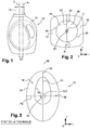
- eccentric neck container We represented at the figure 1 the main “C” axis of the container which passes through the center of the neck 12.
- A axis passing generally through the center of each section horizontal of the container.
- the eccentricity of the neck 12 results in a transverse offset "D1" of the main axis "C” of the container with respect to the axis "A", in the direction of the length of the oblong section of the container.
- the molding units are therefore designed to allow the production of large oblong containers.
- the molding units are made on the model of the molding units used to produce containers with a centered neck, as is for example shown in Fig. figure 2 .
- the molding unit has two mold supports 16 which are mounted articulated with respect to each other along a vertical hinge axis "B".
- a half-mold 18 is received in each support 16.
- the half-molds 18 each comprise a half-cavity which is reconstituted when the two half-molds 18 are joined, in the closed position of the mold supports 16.
- the cavity opens upwards through a passage orifice 20 which is intended to allow the neck 12 of the container to pass.
- the two half-molds 18 being identical by symmetry with respect to a parting line, only the half-mold 18 on the left will be described, the description being applicable to the half-mold 18 on the right by symmetry.
- the half-mold 18 is delimited longitudinally towards the front by a face 22 of the vertical transverse planar front seal which is provided with a mold cavity half (not shown).
- the two half-molds 18 are intended to be joined by pressing their respective joint faces 22 longitudinally against each other to reconstitute the mold cavity, as shown in figure 2 .
- the half-mold 18 is also delimited longitudinally towards the rear by an opposite vertical assembly face 24.
- the assembly face 24 has, in horizontal section, a convexly curved shape.
- the assembly face 24 is intended to be housed in a complementary receiving face of an associated mold support 16.
- the assembly face 24 generally has a semi-cylindrical shape. Thus, when the two half-molds 18 occupy their joined position, their assembly faces 24 have, in horizontal section, a circular shape.
- the orifice 20 for the passage is always arranged astride the parting line between the two half-molds 18. It is common practice for the orifice 20 for the passage of the neck to be centered relative to the circular section of the faces 24. assembly of the half-molds.
- the mold has two one-piece half-molds 18 which are each carried by an associated mold support (not shown).
- the two half-molds 18 being identical by symmetry with respect to a joint plane 26, we will only describe the half-mold 18 of left, the description being applicable to the right half-mold 18 by symmetry.
- the half-mold 18 is delimited longitudinally towards the front by a face 22 of the vertical transverse planar front seal which is provided with one half of the molding cavity 28.
- the seal face 22 extends in the seal plane 26.
- the two half-molds 18 are intended to be joined by pressing their respective joint faces 22 longitudinally against one another in order to reconstitute the mold cavity 28.
- the half-mold 18 is also delimited longitudinally towards the rear by an opposite vertical assembly face 24.
- the assembly face 24 has, in horizontal section, a convexly curved shape.
- the assembly face 24 is intended to be housed in a complementary receiving face of an associated mold support (not shown).
- the assembly face 24 generally has a cylindrical shape formed by the translation of a vertical generating line on the directing curve, formed by the curved shape of the assembly face 24 in horizontal section shown in figure 3 .
- the assembly face 24 has, in horizontal section, the shape of a half-oval. In the joined position, the assembly faces 24 of the two half-molds 18 therefore form a complete oval.
- the assembly face 24 of the mold in the joint position has a first plane "P1" which extends in the joint plane 26.
- the first plane "P1" forms a plane of symmetry for the assembly faces 24.
- the assembly face 24 of the mold in the joined position also has a second vertical plane "P2" of symmetry which extends orthogonally to the first plane “P1” of symmetry.
- the axis "C" of the passage orifice 20 here coincides with the central axis "O" of the mold 18.
- the cavity 28 extends more on one side of the mold 18 than on the other, here transversely towards the top of the figure 3 .
- Such a mold produced according to the state of the art advantageously makes it possible to produce large oblong containers while reducing the longitudinal bulk of the molds compared to molds having, in section, a circular outline, as illustrated in figure 2 .
- a longitudinal transverse plane will be designated as being a "horizontal" plane.
- thermoplastic material in particular of polyethylene terephthalate (PET) or of polypropylene (PP), with an axis of vertical orientation by blowing a preform (not shown).
- PET polyethylene terephthalate
- PP polypropylene
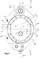
- the molding unit 30 has two mold supports 32A, 32B which are movably mounted between a closed position, shown in figure 4 , and an open position, shown in figure 5 .
- the two mold supports 32A, 32B are mounted to pivot with respect to each other about a vertical axis "B" of hinge 34 arranged along an end edge transverse of the mold supports 32A, 32B.
- Such an arrangement is generally called a "wallet mold”.
- the invention is particularly advantageous with a wallet mold, it is also applicable to mold supports movable in translation with respect to one another.
- Each mold support 32A, 32B is delimited longitudinally by a vertical front receiving face 36 and by a vertical rear face 38.
- the receiving face 36 of each mold support 32A, 32B is turned towards the other mold support 32A, 32B when they occupy their closed position.
- the molding unit 30 also comprises a mold 40 which has a molding cavity 48 having the shape of the container to be obtained by blow molding.
- the cavity 48 opens vertically upwards into a flat upper horizontal face 41 of the mold 40 through a passage orifice 42 intended to allow the neck 12 of the container to be obtained to pass.
- the passage orifice 42 has a central vertical "C" axis.
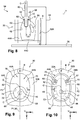
- the mold 40 comprises at least one pair of complementary half-molds 44A, 44B. As is particularly visible at the figure 6 , each half-mold 44A, 44B has a transverse vertical front seal face 46 in which one half of the mold cavity 48 is formed. When the two half-molds 44A, 44B occupy a joint position, as shown in figure 4 , the two half-molds 44A, 44B are pressed against each other by their respective seal face 46 so that their cavity halves reconstitute the mold cavity 48. The seal faces 46 then extend in a plane 50 of transverse vertical seal.
- the passage orifice 42 is arranged astride the joint plane 50, more particularly so that the central axis "C" of the passage orifice 42 is included in the joint plane 50.
- the mold 40 further comprises a base 44C separate from the half-molds 44A, 44B.
- each half-mold 44A, 44B is suitable for forming the body of the container, while the bottom 44C is suitable for forming the bottom of the container.
- the mold comprises only two half-molds.
- the imprint of each half-mold is then suitable for forming the body and the bottom of the container.
- each half-mold 44A, 44B also has a vertical rear assembly face 52 opposite to the seal face 46.
- the assembly face 52 here has the shape of a cylinder sector less than 180 ° so that the assembly faces 52 of the two joint half-molds 44A, 44B has, in horizontal section, an oblong shape, here in almond shape, elongated in a transverse direction.
- the assembly face 52 of each half-mold has the shape of an arc of a circle centered on a vertical reference axis (not shown) offset longitudinally towards the other half-mold 44B, 44A.
- the assembly faces of the two half-molds have, in horizontal section, an elliptical shape or an oval shape, elongated in a transverse direction.
- Each half-mold 44A, 44B is mounted in an associated mold support 32A, 32B by positioning its assembly face 52 against the associated receiving face 36 of the mold support 32A, 32B as shown in FIG. figure 4 .
- the receiving face 36 has a shape complementary to that of the assembly face 52 of the associated half-mold 44A, 44B.
- Each half-mold 44A, 44B is assembled with its associated mold support 32A, 32B by any assembly means already known in the field of molding units with interchangeable mold cavity 48.
- the two half-molds 44A, 44B are able to occupy their position joined by their joint face 46 when the supports 32A, 32B occupy their closed position, as shown in figure 4 , and a disjointed position in which the faces 46 of the joint are moved apart when the supports 32A, 32B occupy their open position, as shown in figure 5 .
- the assembly faces 52 of the two half-molds 44A, 44B have a first plane "P1" which extends along the faces 46 of the joints.
- the first plane “P1” thus corresponds to the joint plane 50.
- the first plane “P1” passes through the center “C” of the passage orifice 42.
- the first plane “P1” also passes here through the hinge axis "B".
- the first plane “P1" of symmetry corresponds here to a transverse vertical plane of symmetry.
- the assembly faces 52 of the two half-molds 44A, 44B have a second plane "P2" of vertical symmetry orthogonal to the first plane “P1” of symmetry.
- the two planes "P1" and “P2" of symmetry intersect at a central vertical axis "O" of the mold 40.
- central "O" axis of the mold 40 does not necessarily coincide with the central "A" axis of the container to be formed.
- FIG. 7 We represented at the figure 7 an installation 54 for forming a thermoplastic container by forming, and in particular by blow molding or stretch blow molding, comprising a horizontal main wheel 56 mounted to rotate about a vertical central rotation axis "Y".
- the main wheel 56 comprises, at its periphery, a plurality of molding units 30, here ten in number, each made as has been described above.
- Each molding unit 30 is arranged so that the joint plane 50 of its half-molds 44A, 44B, in the closed position of the mold supports 32A, 32B, passes through the axis "Y" of rotation of the wheel. 56 main.
- the hinge 34 is turned towards the "Y" axis of rotation of so that the molds 44A, 44B open radially outwards from the main wheel 56.
- each molding unit 30 is carried by the main wheel 56 so that its hinge axis "B" is fixed relative to said main wheel 56.
- each molding unit 30 is associated with a blowing device 58 which is carried by the main wheel 56.
- the blowing device 58 comprises a blowing pipe 60 which is connected to a controlled source of pressurized forming fluid (not shown) and which opens into a connection end with the passage orifice 42 which is centered on the axis. "C" of the passage orifice 42.
- the connection end piece is here a lower bell 62 which is centered on the axis "C" of the orifice 42 for passage of the mold 40 of the associated molding unit 30 when the mold 40 occupies its joined position.
- the bell 62 is mounted to slide vertically along the axis "C" on a support 64 mounted on the main wheel 56 between an active lower position in which the lower edges of the bell 62 are pressed against the upper face 41 of the mold 40 in a joined position to surround the passage orifice 42, and an upper retracted position in which the bell 62 is spaced from the upper face 41 to allow the opening and closing of the mold supports 32A, 32B.
- the active position of the bell 62 is for example shown in figure 8 .
- the sliding axis "C" of the bell 62 is fixed relative to the main wheel 56.
- the bell 62 In its active position, the bell 62 is capable of filling a hot preform 63 with pressurized forming fluid through its neck 12 in order to press the walls thereof against the cavity 48 to form the body of the container.
- the central "C" axis of the passage orifice 42 is transversely offset by a distance “D2" with respect to the central "O" axis of the mold 40.
- the passage orifice 42 is offset by a distance “D” in a direction opposite to that of the hinge axis "B” so that the central axis "O” of the mold is interposed between the axis Central “C” of the orifice 42 of passage and the axis "B” of hinge.
- the offset of the axis "C" of the passage orifice 42 in the direction of the peripheral edge of the main wheel 56 advantageously allows better use of the volume between the mold supports 32A, 32B during the manufacture of sectional containers. oblong. This makes it possible in particular to reduce the bulk, in particular transverse, of the mold supports 32A, 32B relative to a molding unit of the state of the art in which the passage orifice is centered relative to the mold.
- the mold 40 is advantageously equipped with two boxing pistons 66 which are each mounted to slide in a working chamber 67 produced in a half-mold 44A, 44B associated between a position retracted relative to the mold cavity 48 and an extended position in the mold cavity 48.
- the boxing pistons 66 are for example actuated by means of the controlled source of pressurized forming fluid.
- the boxing pistons 66 are arranged in the thickness of each half-mold 44A, 44B near the axis "B" of the hinge.
- the boxing pistons 66 are more particularly visible in the example shown in figure 10 in which the molding cavity 48 has been shown in broken lines.
- the boxing pistons 66 are more particularly mounted generally facing each other, in a substantially longitudinal sliding direction.
- the boxing pistons 66 are then controlled from their retracted position to their position extended to depress the wall of the container against the pressure of the forming fluid to form the handle 14.
- the boxing pistons 66 are held extended until the wall of the container body has acquired its final shape.
- the offset of the orifice 42 for the passage of the neck 12 towards the peripheral edge of the main wheel 56 advantageously makes it possible to offset a part of the cavity 48 transversely towards the peripheral edge of the main wheel 56 relative to a mold with a passage hole. center.
- This very advantageously makes it possible to free up the space necessary for arranging boxing pistons 66 making it possible to obtain a thrust force sufficient to greatly exceed the pressure of the forming fluid contained in the container during its forming.
- the arrangement of such boxing pistons 66 in a molding unit 30 produced according to the teachings of the invention makes it possible in particular to obtain a mold 40 provided with boxing pistons 66 while keeping a small footprint, in particular transverse, reduced.
- Such a configuration thus allows this molding unit to be installed on a standard carousel as a replacement for a mold with a centered passage orifice.
- a mold comprising boxing pistons should be installed on a carousel of larger diameter than a standard carousel.
- Each half-mold 44A, 44B is here made in one piece.
- each half-mold 44A, 44B is made in two distinct parts formed by a shell 68 and by a shell holder 70.
- the internal shell 68 is delimited longitudinally by a front transverse vertical face forming the seal face 46 of the half-mold 44A and by a rear face, opposite to the face 46 of seal, forming a mounting face 72.
- the mounting face 72 has a convex shape.
- the outer shell holder 70 is delimited longitudinally by a front receiving face 74 of a shape complementary to that of the mounting face 72.
- the shell 68 is intended to be housed in the shell holder 70, its mounting face 72 being pressed against the receiving face 74 of the shell holder 70.
- the shell holder 70 is also delimited towards the rear by a rear face opposite which forms the assembly face 52 of the half-mold 44A.
- the shell 68 carries the mold cavity half 48.
- the shell holder 70 is equipped with means (not shown) for cooling the shell 68.
- the mounting face 72 has, in horizontal section, the shape of a semicircle which is centered on the central axis "C" of the passage orifice 42. This is for example the case of a mold 40 used to produce containers having a centered neck 12.
- the shell 68 is arranged transversely eccentric with respect to the assembly face 52 in the shell holder 70 as shown on figure 9 .
- the receiving face 74 of the shell holder 70 is offset transversely away from the hinge axis "B” with respect to the second plane "P2" of symmetry of the assembly face 52 of the mold 40.
- the mounting face 72 is arranged concentrically with the assembly face 52 of the mold 40.
- the molding unit 30 produced according to any one of the embodiments described above allows advantageously to produce the containers with an eccentric neck while offering a reduced size compared to the molding units of the state of the art.
- the molding units produced according to the teachings of the invention also make it possible easily to produce molds equipped with boxing pistons without it being necessary to increase the size of the molding unit.
- the molding units produced according to the teachings of the invention also make it possible to easily produce containers with a centered neck by replacing the molds or simply the shell when each half-mold is made in two parts.
Landscapes
- Engineering & Computer Science (AREA)
- Manufacturing & Machinery (AREA)
- Mechanical Engineering (AREA)
- Moulds For Moulding Plastics Or The Like (AREA)
- Blow-Moulding Or Thermoforming Of Plastics Or The Like (AREA)
Description
L'invention concerne une unité de moulage pour le formage de récipients en matériau thermoplastique à partir de préformes, notamment par soufflage ou étirage-soufflage, l'unité de moulage comportant :
- deux supports de moule articulés autour d'un axe vertical de charnière entre une position ouverte et une position fermée ;
- un moule comportant au moins deux demi-moules dont chacun destiné à être monté sur l'un des supports de moule associé, chaque demi-moule étant délimité par une face de joint avant et par une face d'assemblage arrière, les deux demi-moules étant susceptibles d'occuper une position jointe par leur face de joint lorsque les supports de moule occupent leur position fermée ;
- une cavité de moulage qui est réalisée en deux partie dans chaque face de joint et qui est reconstituée lorsque le moule occupe sa position jointe, la cavité débouchant verticalement vers le haut par un orifice de passage destiné à laisser passer un col de la préforme.
- two mold supports articulated about a vertical hinge axis between an open position and a closed position;
- a mold comprising at least two half-molds each of which is intended to be mounted on one of the associated mold supports, each half-mold being delimited by a front seal face and by a rear assembly face, the two half-molds molds being capable of occupying a joint position by their joint face when the mold supports occupy their closed position;
- a molding cavity which is produced in two parts in each seal face and which is reconstituted when the mold occupies its joint position, the cavity opening vertically upwards through a passage opening intended to allow a neck of the preform to pass.
Il est connu de fabriquer en grandes séries des récipients, notamment des bouteilles, en matières thermoplastiques par soufflage ou étirage-soufflage de préformes. A cet effet, les préformes chaudes sont insérées dans des unités de moulage présentant une cavité de moulage de la forme du récipient à obtenir. Les documents
Pour permettre de réaliser les récipients en grandes séries, plusieurs unités de moulage sont agencées sur une roue principale formant un carrousel rotatif d'une installation de formage. Ceci permet de former successivement plusieurs récipients pendant leur déplacement entre un point d'entrée et un point de sortie.To enable the containers to be produced in large series, several molding units are arranged on a main wheel forming a rotating carousel of a forming installation. This makes it possible to successively form several containers during their movement between an entry point and an exit point.
En phase de fabrication, les préformes sont amenées à une unité de moulage de l'installation de formage à laquelle est associé un dispositif de formage par application d'au moins un fluide de formage sous pression, gazeux et/ou liquide, dans la préforme. Le formage de la préforme est par exemple obtenu par soufflage ou étirage-soufflage au moyen d'un gaz sous pressions, tel que de l'air.During the manufacturing phase, the preforms are brought to a molding unit of the forming installation with which is associated a forming device by applying at least one pressurized forming fluid, gaseous and / or liquid, in the preform. . The forming of the preform is for example obtained by blow molding or stretch blow molding by means of a pressurized gas, such as air.
Dans une installation de formage à carrousel rotatif, chaque unité de moulage comporte au moins un moule équipé d'une cavité de moulage. Le moule est réalisé en au moins deux demi-moules portant chacun une empreinte de la moitié de la cavité de moulage. Les demi-moules sont portés par deux supports de moule associés. Les supports de moule sont mobiles entre une position ouverte, dans laquelle les deux demi-moules sont écartés pour permettre l'extraction d'un récipient moulé et l'introduction d'une préforme, et une position fermée dans laquelle les deux demi-moules occupent une position jointe pour reconstituer la cavité de moulage pendant l'opération de formage.In a rotary carousel forming installation, each molding unit comprises at least one mold equipped with a mold cavity. The mold is made of at least two half-molds each bearing an imprint of half of the mold cavity. The half-molds are carried by two associated mold supports. The mold supports are movable between an open position, in which the two half-molds are separated to allow the extraction of a molded container and the introduction of a preform, and a closed position in which the two half-molds occupy a joint position to reconstitute the mold cavity during the forming operation.
Les deux supports de moule sont montés pivotants l'un par rapport à l'autre, articulés par une charnière verticale. Une telle unité de moulage est aussi connue sous l'appellation "moule portefeuille".The two mold supports are mounted to pivot with respect to each other, articulated by a vertical hinge. Such a molding unit is also known under the name "wallet mold".
En variante, les supports de moule sont montés coulissant l'un par rapport à l'autre.As a variant, the mold supports are mounted to slide relative to one another.
Les récipients obtenus par un tel procédé sont notamment des bouteilles. Une telle bouteille comporte un corps délimitant un volume destiné à recevoir un produit, par exemple un liquide ou une poudre. Le corps comporte généralement un fond plat qui permet de poser la bouteille debout. La bouteille est généralement ouverte vers le haut par un col qui est susceptible d'être bouché. Le col permet à l'utilisateur de verser le produit contenu dans la bouteille. Pour la suite de la description, on définit l'axe principal du récipient comme étant l'axe vertical passant par le centre du col.The containers obtained by such a process are in particular bottles. Such a bottle comprises a body delimiting a volume intended to receive a product, for example a liquid or a powder. The body usually has a flat bottom that allows the bottle to be placed upright. The bottle is usually opened at the top by a neck which is likely to be corked. The neck allows the user to pour the product contained in the bottle. For the remainder of the description, the main axis of the container is defined as being the vertical axis passing through the center of the neck.
Dans de nombreux domaine, il est connu de réaliser une bouteille avec le col centré par rapport à la section horizontale du corps de la bouteille. Par la suite, un tel récipient sera appelé "récipient à col centré". C'est notamment le cas des bouteilles d'eau. Dans ce cas, l'axe principal du récipient passe par le centre des sections horizontales du récipient.In many fields, it is known to produce a bottle with the neck centered with respect to the horizontal section of the body of the bottle. Hereinafter, such a container will be called a "center neck container". This is particularly the case with water bottles. In this case, the main axis of the container passes through the center of the horizontal sections of the container.
Les fabricants de récipients sont souvent amenés à changer le modèle de récipients produits. C'est notamment le cas des fabricants qui produisent des récipients ou bouteilles destinés à contenir des produits d'entretien ou d'hygiène, dits "home personal care". Pour permettre ce changement de modèle, il est connu de concevoir des unités de moulage permettant de remplacer facilement et rapidement les éléments de moule comportant la cavité.Container manufacturers are often required to change the model of the containers produced. This is particularly the case for manufacturers who produce containers or bottles intended to contain cleaning or hygiene products, known as "home personal care". To allow this model change, it is known to design molding units making it possible to easily and quickly replace the mold elements comprising the cavity.
Comme cela est représenté à la
En outre, certains récipients de grande dimension présentent une contenance très grande, par exemple de l'ordre de plusieurs litres. C'est par exemple le cas de certaines bouteilles destinées à contenir de la lessive.In addition, certain large containers have a very large capacity, for example of the order of several liters. This is for example the case of certain bottles intended to contain detergent.
Par ailleurs, dans ce type de récipient du domaine "home personal care", il est très fréquent qu'un col 12 du récipient soit excentré par rapport au centre de la section horizontale du récipient 10. Par la suite, un tel récipient sera appelé "récipient à col excentré". On a représenté à la
Ceci permet notamment de réserver une place dans la paroi du récipient pour réaliser une poignée 14 du côté opposé à celui du col 12. En outre, l'excentration du col 12 par rapport à la poignée 14 permet de faciliter l'utilisation du récipient pour l'utilisateur final en déplaçant le centre de gravité du récipient vers le col 12 lorsque le récipient est incliné pour permettre de verser son contenu.This makes it possible in particular to reserve a place in the wall of the container to produce a
Les unités de moulage sont donc prévues pour permettre la production de récipients oblongs de grande dimension.The molding units are therefore designed to allow the production of large oblong containers.
De manière traditionnelle, les unités de moulage sont réalisées sur le modèle des unités de moulage utilisées pour produire des récipients à col centré, comme cela est par exemple représenté à la
Les deux demi-moules 18 étant identiques par symétrie par rapport à un plan de joint, on ne décrira que le demi-moule 18 de gauche, la description étant applicable au demi-moule 18 de droite par symétrie.The two half-
Ainsi, le demi-moule 18 est délimité longitudinalement vers l'avant par une face 22 de joint avant plane transversale verticale qui est munie d'une moitié de cavité de moulage (non représentée). Dans une position jointe, les deux demi-moules 18 sont destinés à être joints en plaquant leurs faces 22 de joint respectives longitudinalement l'une contre l'autre pour reconstituer la cavité de moulage, comme représenté à la
Le demi-moule 18 est aussi délimité longitudinalement vers l'arrière par une face 24 d'assemblage verticale opposée. La face 24 d'assemblage présente, en coupe horizontale, une forme courbée de manière convexe. La face 24 d'assemblage est destinée à être logée dans une face de réception complémentaire d'un support 16 de moule associé. La face 24 d'assemblage présente généralement une forme hémicylindrique. Ainsi, lorsque les deux demi-moules 18 occupent leur position jointe, leurs faces 24 d'assemblage présentent, en coupe horizontale, une forme circulaire.The half-
L'orifice 20 de passage est toujours agencé à cheval sur le plan de joint entre les deux demi-moules 18. Il est d'usage courant que l'orifice 20 de passage du col soit centré par rapport à la section circulaire des faces 24 d'assemblage des demi-moules.The
Cependant, un tel mode de réalisation, dans lequel le moule présente une face d'assemblage cylindrique de révolution, peut devenir très encombrant lorsqu'il s'agit de réaliser des récipients du domaine "home personal care" présentant une section oblongue, un volume important et un col excentré.However, such an embodiment, in which the mold has a cylindrical assembly face of revolution, can become very bulky when it comes to making containers from the "home personal care" field having an oblong section, a volume. important and an eccentric collar.
Pour que le carrousel puisse porter un nombre assez élevé d'unités de moulage, par exemple une dizaine, tout en demeurant assez compact, il est connu de réaliser des unités de moulage comportant des moules dits "elliptiques". Ces moules elliptiques présentent, en coupe horizontale, un contour de forme oblongue.In order for the carousel to be able to carry a fairly large number of molding units, for example ten, while remaining fairly compact, it is known practice to produce molding units comprising so-called “elliptical” molds. These elliptical molds have, in horizontal section, an oblong contour.
On a représenté à la
Le moule présente deux demi-moules 18 monoblocs qui sont chacun porté par un support de moule associé (non représenté). Les deux demi-moules 18 étant identiques par symétrie par rapport à un plan 26 de joint, on ne décrira que le demi-moule 18 de gauche, la description étant applicable au demi-moule 18 de droite par symétrie.The mold has two one-piece half-
Ainsi, le demi-moule 18 est délimité longitudinalement vers l'avant par une face 22 de joint avant plane transversale verticale qui est munie d'une moitié de la cavité 28 de moulage. La face 22 de joint s'étend dans le plan 26 de joint. Dans une position jointe, les deux demi-moules 18 sont destinés à être joints en plaquant leurs faces 22 de joint respectives longitudinalement l'une contre l'autre pour reconstituer la cavité 28 de moulage.Thus, the half-
Le demi-moule 18 est aussi délimité longitudinalement vers l'arrière par une face 24 d'assemblage verticale opposée. La face 24 d'assemblage présente, en coupe horizontale, une forme courbée de manière convexe. La face 24 d'assemblage est destinée à être logée dans une face de réception complémentaire d'un support de moule associé (non représenté). La face 24 d'assemblage présente généralement une forme cylindrique formée par la translation d'une droite génératrice verticale sur la courbe directrice, formée par la forme courbée de la face 24 d'assemblage en coupe horizontale représentée à la
De manière connue, la face 24 d'assemblage présente, en coupe horizontale, la forme d'un demi-ovale. En position jointe, les faces 24 d'assemblage des deux demi-moules 18 forment donc un ovale complet.In known manner, the
La face 24 d'assemblage du moule en position jointe présente un premier plan "P1" qui s'étend dans le plan 26 de joint. Dans l'exemple représenté aux figures, le premier plan "P1" forme un plan de symétrie pour les faces 24 d'assemblage.The assembly face 24 of the mold in the joint position has a first plane "P1" which extends in the
De même, la face 24 d'assemblage du moule en position jointe présente en outre un deuxième plan "P2" vertical de symétrie qui s'étend orthogonalement au premier plan "P1" de symétrie. Les deux plans "P1" et "P2" de symétrie de coupe en un axe vertical "O" central. Comme on peut le constater, l'axe "C" de l'orifice 20 de passage coïncide ici avec l'axe "O" central du moule 18.Likewise, the
Ceci est toujours le cas, même lorsque l'axe "C" principal du récipient à obtenir est décalé par rapport à la section du récipient, comme cela est par exemple illustré à la
Un tel moule réalisé selon l'état de la technique permet avantageusement de réaliser des récipients oblongs de grande dimension en diminuant l'encombrement longitudinal des moules par rapport à des moules présentant, en section, un contour circulaire, tel qu'illustrés à la
Cependant, l'orifice 20 de passage étant centré par rapport au moule 18 mais excentré par rapport à la section du récipient à obtenir, une partie du volume du moule 18, comme représenté en bas de la
En outre, il n'est pas possible de modifier la position de l'orifice 20 de passage du col car la position de dernier est déterminée par la position du dispositif de formage qui est associé à l'unité de moulage. Or, un tel dispositif de formage est encombrant et est généralement monté à une position fixe sur la roue principale de l'installation de moulage.Further, it is not possible to change the position of the
L'invention propose une unité de moulage pour le formage de récipients en matériau thermoplastique à partir de préformes, notamment par soufflage ou étirage-soufflage, l'unité de moulage comportant :
- deux supports de moule mobiles entre une position ouverte et une position fermée ;
- un moule comportant au moins deux demi-moules dont chacun destiné à être monté sur l'un des supports de moule associé, chaque demi-moule étant délimité par une face de joint avant et par une face d'assemblage arrière, les deux demi-moules étant susceptibles d'occuper une position jointe par leur face de joint lorsque les supports de moule occupent leur position fermée ;
- une cavité de moulage qui est réalisée en deux partie dans chaque face de joint et qui est reconstituée lorsque le moule occupe sa position jointe, la cavité débouchant verticalement vers le haut par un orifice de passage destiné à laisser passer un col de la préforme ;
- un premier plan vertical transversal qui s'étend le long des faces de joints et qui passe par le centre de l'orifice de passage, et
- un deuxième plan de symétrie vertical orthogonal au premier plan de symétrie, les deux plans de symétrie se croisant à un axe vertical central du moule ;
- two mold supports movable between an open position and a closed position;
- a mold comprising at least two half-molds each of which is intended to be mounted on one of the associated mold supports, each half-mold being delimited by a gasket face front and by a rear assembly face, the two half-molds being capable of occupying a position joined by their joint face when the mold supports occupy their closed position;
- a molding cavity which is produced in two parts in each seal face and which is reconstituted when the mold occupies its joint position, the cavity opening vertically upwards through a passage opening intended to allow a neck of the preform to pass;
- a first transverse vertical plane which extends along the faces of the joints and which passes through the center of the passage opening, and
- a second vertical plane of symmetry orthogonal to the first plane of symmetry, the two planes of symmetry intersecting at a central vertical axis of the mold;
Selon d'autres caractéristiques de l'unité de moulage réalisée selon les enseignements de l'invention :
- le premier plan passe par un axe de charnière entre les deux supports de moule, l'orifice de passage étant décalé dans une direction opposée à celle de l'axe de charnière de manière que l'axe central du moule est interposé entre l'axe central de l'orifice de passage et l'axe de charnière ;
- en position jointe du moule, les faces d'assemblage présentent une section horizontale elliptique ;
- en position jointe du moule, la face d'assemblage de chaque demi-moule présente une section horizontale en forme d'arc de cercle qui s'étend sur un secteur inférieur à 180° ;
- chaque demi-moule est réalisé en une seule pièce ;
- chaque demi-moule est réalisé en deux parties :
- -- une coquille interne qui est délimitée longitudinalement par une face avant formant la face de joint du demi-moule et par une face arrière, opposée à la face de joint, et formant une face de montage de forme convexe ;
- -- un porte-coquille externe qui est délimité longitudinalement par une face de réception avant de forme complémentaire à celle de la face de montage de la coquille et dans laquelle la face de montage de la coquille est logée et par une face arrière opposée qui forme la face d'assemblage du demi-moule ;
- en coupe horizontale, la face de montage de la coquille présente une forme d'arc de cercle ;
- chaque face de montage présentant, en coupe horizontale, une forme de demi-cercle centré sur l'axe central de l'orifice de passage ;
- la face de montage est concentrique à la face d'assemblage du demi-moule associé ;
- l'unité de moulage comporte deux pistons de boxage qui sont chacun montés coulissants dans un demi-moule associé entre une position rétractée par rapport à la cavité de moulage et une position étendue dans la cavité de moulage, les pistons de boxage étant agencés dans l'épaisseur de chaque demi-moule à proximité de l'axe de charnière.
- the first plane passes through a hinge axis between the two mold supports, the passage opening being offset in a direction opposite to that of the hinge axis so that the central axis of the mold is interposed between the axis central passage hole and hinge pin;
- in the joint position of the mold, the assembly faces have an elliptical horizontal section;
- in the joint position of the mold, the assembly face of each half-mold has a horizontal section in the form of an arc of a circle which extends over a sector less than 180 °;
- each half-mold is made in one piece;
- each half-mold is made in two parts:
- an internal shell which is delimited longitudinally by a front face forming the seal face of the half-mold and by a rear face, opposite the seal face, and forming a convex-shaped mounting face;
- - an outer shell holder which is delimited longitudinally by a front receiving face of complementary shape to that of the mounting face of the shell and in which the mounting face of the shell is housed and by an opposite rear face which forms the assembly face of the half-mold;
- in horizontal section, the mounting face of the shell has the shape of a circular arc;
- each mounting face having, in horizontal section, the shape of a semi-circle centered on the central axis of the passage opening;
- the assembly face is concentric with the assembly face of the associated half-mold;
- the molding unit comprises two boxing pistons which are each slidably mounted in an associated half-mold between a retracted position with respect to the molding cavity and an extended position in the molding cavity, the boxing pistons being arranged in the 'thickness of each half-mold near the hinge axis.
L'invention concerne aussi une installation de formage comportant :
- une roue principale rotative ;
- une pluralité d'unités de moulage réalisées selon enseignements de l'invention, les unités de moulage étant réparties régulièrement à la périphérie de la roue principale ;
- des dispositifs de formage comportant un embout de raccordement avec l'orifice de passage qui est centré sur l'axe de l'orifice de passage.
- a rotating main wheel;
- a plurality of molding units produced according to the teachings of the invention, the molding units being regularly distributed around the periphery of the main wheel;
- forming devices comprising a connecting piece with the passage orifice which is centered on the axis of the passage orifice.
D'autres caractéristiques et avantages de l'invention apparaitront au cours de la lecture de la description détaillée qui va suivre pour la compréhension de laquelle on se reportera aux dessins annexés dans lesquels :
- la
figure 1 est une vue de côté qui représente un récipient à section oblongue et à col excentré ; - la
figure 2 est une vue de dessus qui représente une unité de moulage réalisé selon un premier état de la technique connu ; - la
figure 3 est une vue de dessus qui représente un moule réalisé selon un deuxième état de la technique connu ; - la
figure 4 est une vue de dessus qui représente une unité de moulage réalisée selon un premier mode de réalisation de l'invention, les supports de moule occupant une position fermée et les demi-moules une position jointe ; - la
figure 5 est une vue similaire à celle de lafigure 4 qui représente les supports de moule en position ouverte et les demi-moules en position écartée ; - la
figure 6 est une vue en perspective qui représente l'un des demi-moules qui équipe l'unité de moulage de lafigure 4 ; - la
figure 7 est une vue de dessus qui représente schématiquement une installation de formage comportant une roue principale tournante équipée d'une pluralité d'unités de moulage réalisées selon le premier mode de réalisation de l'invention ; - la
figure 8 est une vue en coupe transversale verticale selon le plan de coupe 8-8 de lafigure 7 qui représente une unité de moulage montée sur la roue principale de l'installation de formage et équipée d'un dispositif de formage ; - la
figure 9 est une vue de dessus qui représente schématiquement une unité de formage réalisée selon un deuxième mode de réalisation de l'invention ; - la
figure 10 est une vue similaire à celle de lafigure 9 qui représente l'unité de formage réalisée selon le deuxième mode de réalisation de l'invention dans une autre configuration.
- the
figure 1 is a side view which shows a container with an oblong section and an eccentric neck; - the
figure 2 is a top view which shows a molding unit produced according to a first known state of the art; - the
figure 3 is a top view which shows a mold produced according to a second known state of the art; - the
figure 4 is a top view which shows a molding unit produced according to a first embodiment of the invention, the mold supports occupying a closed position and the half-molds a joined position; - the
figure 5 is a view similar to that of thefigure 4 which shows the mold supports in the open position and the half-molds in the spread position; - the
figure 6 is a perspective view which shows one of the half-molds which equips the molding unit of thefigure 4 ; - the
figure 7 is a top view which schematically shows a forming installation comprising a rotating main wheel equipped with a plurality of molding units produced according to the first embodiment of the invention; - the
figure 8 is a vertical cross-sectional view along the sectional plane 8-8 of thefigure 7 which represents a molding unit mounted on the main wheel of the forming plant and equipped with a forming device; - the
figure 9 is a top view which schematically shows a forming unit produced according to a second embodiment of the invention; - the
figure 10 is a view similar to that of thefigure 9 which represents the forming unit produced according to the second embodiment of the invention in another configuration.
Dans la suite de la description, des éléments présentant une structure identique ou des fonctions analogues seront désignés par des mêmes références.In the remainder of the description, elements having an identical structure or similar functions will be designated by the same references.
Dans la description et dans les revendications, on adoptera à titre non limitatif un repère orthogonal associé à chaque demi-moule et présentant des orientations :
- longitudinale "L" dirigée d'arrière en avant en direction de l'autre demi-moule en position jointe ;
- transversale "T" dirigée de gauche à droite ;
- verticale "V" dirigée de bas en haut, la direction verticale étant indépendante de la direction de la gravité.
- longitudinal "L" directed from rear to front in the direction of the other half-mold in the joined position;
- transverse "T" directed from left to right;
- vertical "V" directed from bottom to top, the vertical direction being independent of the direction of gravity.
Par la suite, on désignera un plan transversal longitudinal comme étant un plan "horizontal".Hereinafter, a longitudinal transverse plane will be designated as being a "horizontal" plane.
On a représenté aux
L'unité 30 de moulage comporte deux supports 32A, 32B de moule qui sont montés mobiles entre une position fermée, représentée à la
Quoique l'invention soit particulièrement avantageuse avec un moule portefeuille, elle est aussi applicable à des supports de moule mobiles en translation l'un par rapport à l'autre.Although the invention is particularly advantageous with a wallet mold, it is also applicable to mold supports movable in translation with respect to one another.
Chaque support 32A, 32B de moule est délimité longitudinalement par une face 36 de réception avant verticale et par une face 38 arrière verticale. La face 36 de réception de chaque support 32A, 32B de moule est tournée vers l'autre support 32A, 32B de moule lorsqu'ils occupent leur position fermée.Each
L'unité 30 de moulage comporte aussi un moule 40 qui présente une cavité 48 de moulage présentant la forme du récipient à obtenir par soufflage. La cavité 48 est débouchante verticalement vers le haut dans une face 41 supérieure horizontale plane du moule 40 par un orifice 42 de passage destiné à laisser passer le col 12 du récipient à obtenir. L'orifice 42 de passage présente un axe "C" vertical central.The
Le moule 40 comporte au moins une paire de demi-moules 44A, 44B complémentaires. Comme cela est particulièrement visible à la
L'orifice 42 de passage est agencé à cheval sur le plan 50 de joint, plus particulièrement de manière que l'axe "C" central de l'orifice 42 de passage soit inclus dans le plan 50 de joint.The
Dans le mode de réalisation représenté à la
En variante non représentée, le moule comporte uniquement deux demi-moule. L'empreinte de chaque demi-moule est alors propre à former le corps et le fond du récipient.In a variant not shown, the mold comprises only two half-molds. The imprint of each half-mold is then suitable for forming the body and the bottom of the container.
En se reportant à nouveau à la
En variante, les faces d'assemblage des deux demi-moules présentent, en coupe horizontale, une forme elliptique ou une forme ovale, allongée dans une direction transversale.As a variant, the assembly faces of the two half-molds have, in horizontal section, an elliptical shape or an oval shape, elongated in a transverse direction.
Chaque demi-moule 44A, 44B est monté dans un support 32A, 32B de moule associé en positionnant sa face 52 d'assemblage contre la face 36 de réception associée du support 32A, 32B de moule comme représenté à la
Les deux demi-moules 44A, 44B sont susceptibles d'occuper leur position jointe par leur face 46 de joint lorsque les supports 32A, 32B occupent leur position fermée, comme représentée à la
En position jointe, représentée à la
En outre, toujours en position jointe, les faces 52 d'assemblage des deux demi-moules 44A, 44B présentent un deuxième plan "P2" de symétrie vertical orthogonal au premier plan "P1" de symétrie. Les deux plans "P1" et "P2" de symétrie se croisent en un axe "O" vertical central du moule 40.In addition, still in the joint position, the assembly faces 52 of the two half-
On remarquera que l'axe "O" central du moule 40 ne coïncide pas nécessairement avec l'axe "A" central du récipient à former.It will be noted that the central "O" axis of the
Cependant, lorsque l'axe "O" central du moule 40 coïncide avec l'axe "A" central du récipient à former, cela permet avantageusement de mieux répartir la matière du moule 40 par rapport aux supports 32A, 32B de moule.However, when the central “O” axis of the
On a représenté à la
Comme cela est représenté à la
Par ailleurs, chaque unité 30 de moulage est associée à un dispositif 58 de soufflage qui est porté par la roue 56 principale. Le dispositif 58 de soufflage comporte une conduite 60 de soufflage qui est raccordée à une source commandée de fluide de formage sous pression (non représentée) et qui débouche dans un embout de raccordement avec l'orifice 42 de passage qui est centré sur l'axe "C" de l'orifice 42 de passage. L'embout de raccordement est ici une cloche 62 inférieure qui est centrée sur l'axe "C" de l'orifice 42 de passage du moule 40 de l'unité 30 de moulage associée lorsque le moule 40 occupe sa position jointe. La cloche 62 est montée coulissante verticalement le long de l'axe "C" sur un support 64 monté sur la roue 56 principale entre une position inférieure active dans laquelle des bords inférieurs de la cloche 62 sont plaqués contre la face 41 supérieure du moule 40 en position jointe pour entourer l'orifice 42 de passage, et une position supérieure rétractée dans laquelle la cloche 62 est écartée de la face 41 supérieure pour permettre l'ouverture et la fermeture des supports 32A, 32B de moule.Furthermore, each
La position active de la cloche 62 est par exemple représentée à la
Selon les enseignements de l'invention, l'axe "C" central de l'orifice 42 de passage est décalé transversalement d'une distance "D2" par rapport à l'axe "O" central du moule 40.Plus particulièrement, l'orifice 42 de passage est décalé d'une distance "D" dans une direction opposée à celle de l'axe "B" de charnière de manière que l'axe "O" central du moule soit interposé entre l'axe "C" central de l'orifice 42 de passage et l'axe "B" de charnière.According to the teachings of the invention, the central "C" axis of the
Le décalage de l'axe "C" de l'orifice 42 de passage en direction du bord périphérique de la roue 56 principale permet avantageusement de mieux utiliser le volume compris entre les supports 32A, 32B de moule lors de la fabrication de récipients à section oblongue. Cela permet notamment de diminuer l'encombrement, notamment transversal, des supports 32A, 32B de moule par rapport à une unité de moulage de l'état de la technique dans lequel l'orifice de passage est centré par rapport au moule.The offset of the axis "C" of the
Par ailleurs, pour former la poignée 14 du récipient, le moule 40 est avantageusement équipé de deux pistons 66 de boxage qui sont chacun montés coulissants dans une chambre 67 de travail réalisé dans un demi-moule 44A, 44B associé entre une position rétractée par rapport à la cavité 48 de moulage et une position étendue dans la cavité 48 de moulage. Les pistons 66 de boxage sont par exemple actionnés au moyen de la source commandée de fluide de formage sous pression. Les pistons 66 de boxage sont agencés dans l'épaisseur de chaque demi-moule 44A, 44B à proximité de l'axe "B" de charnière. Les pistons 66 de boxage sont plus particulièrement visibles dans l'exemple représenté à la
Les pistons 66 de boxage sont plus particulièrement montés globalement en vis-à-vis l'un de l'autre, selon une direction de coulissement sensiblement longitudinale. Ainsi, lors du formage du récipient, lorsque le récipient a subi une opération de soufflage qui a plaqué sa paroi contre la cavité 48 et que la cloche 62 occupe sa position active, la pression du fluide de formage sous pression est maintenue à l'intérieur du récipient. Les pistons 66 de boxage sont alors commandés depuis leur position rétractée vers leur position étendue pour enfoncer la paroi du récipient à l'encontre de la pression du fluide de formage pour former la poignée 14. Les pistons 66 de boxage sont maintenus étendus jusqu'à ce que la paroi du corps du récipient ait acquis sa forme définitive.The
Le décalage de l'orifice 42 de passage du col 12 vers le bord périphérique de la roue 56 principale permet avantageusement de décaler une partie de la cavité 48 transversalement vers le bord périphérique de la roue 56 principale par rapport à un moule à orifice de passage centré. Ceci permet très avantageusement de libérer la place nécessaire pour agencer des pistons 66 de boxage permettant d'obtenir une force de poussée suffisante pour surpasser largement la pression du fluide de formage contenue dans le récipient au cours de son formage. L'agencement de tels pistons 66 de boxage dans une unité 30 de moulage réalisée selon les enseignements de l'invention permet notamment d'obtenir un moule 40 muni de pistons 66 de boxage tout en conservant un encombrement, notamment transversal, réduit.The offset of the
Une telle configuration permet ainsi à cette unité de moulage d'être installée sur un carrousel standard en remplacement de moule à orifice de passage centré. En l'absence de décalage de l'axe de l'orifice, un tel moule comportant des pistons de boxage devrait être installé sur un carrousel de diamètre plus grand qu'un carrousel standard.Such a configuration thus allows this molding unit to be installed on a standard carousel as a replacement for a mold with a centered passage orifice. In the absence of offset of the axis of the orifice, such a mold comprising boxing pistons should be installed on a carousel of larger diameter than a standard carousel.
Chaque demi-moule 44A, 44B est ici réalisé en une seule pièce.Each half-
Selon un deuxième mode de réalisation de l'invention qui est représenté aux
La coquille 68 interne est délimitée longitudinalement par une face verticale transversale avant formant la face 46 de joint du demi-moule 44A et par une face arrière, opposée à la face 46 de joint, formant une face 72 de montage. En coupe horizontale, la face 72 de montage présente une forme convexe.The
Le porte-coquille 70 externe est délimité longitudinalement par une face 74 de réception avant de forme complémentaire à celle de la face 72 de montage. La coquille 68 est destinée à être logée dans le porte-coquille 70, sa face 72 de montage étant plaquée contre la face 74 de réception du porte-coquille 70. Le porte-coquille 70 est aussi délimité vers l'arrière par une face arrière opposée qui forme la face 52 d'assemblage du demi-moule 44A.The
Ainsi, la coquille 68 porte la moitié de cavité 48 de moulage. Généralement, le porte-coquille 70 est équipé de moyens de refroidissement (non représentés) de la coquille 68.Thus, the
Selon une première variante de réalisation du deuxième mode de réalisation qui est représentée à la
Selon cette première variante, pour que l'axe "C" central de l'orifice 42 de passage coïncide avec l'axe de coulissement de la cloche 62, la coquille 68 est agencée excentrée transversalement par rapport à la face 52 d'assemblage dans le porte-coquille 70 comme cela est représenté à la
Selon une deuxième variante de réalisation du deuxième mode de réalisation qui est représentée à la
L'unité 30 de moulage réalisée selon l'un quelconque des modes de réalisation précédemment décrit permet avantageusement de réaliser les récipients à col excentré tout en proposant un encombrement réduit par rapport aux unités de moulage de l'état de la technique.The
Les unités de moulage réalisées selon les enseignements de l'invention permettent en outre de réaliser facilement des moules équipés de pistons de boxage sans qu'il ne soit nécessaire d'augmenter l'encombrement de l'unité de moulage.The molding units produced according to the teachings of the invention also make it possible easily to produce molds equipped with boxing pistons without it being necessary to increase the size of the molding unit.
Les unités de moulage réalisées selon les enseignements de l'invention permet de plus de réaliser facilement des récipients à col centré en remplaçant les moules ou simplement la coquille lorsque chaque demi-moule est réalisé en deux parties.The molding units produced according to the teachings of the invention also make it possible to easily produce containers with a centered neck by replacing the molds or simply the shell when each half-mold is made in two parts.
Claims (11)
- Moulding unit (30) for forming containers made of thermoplastic material from preforms (63), in particular by blow-moulding or stretch-blow-moulding, the moulding unit (30) having:- two mould supports (32A, 32B) able to move between an open position and a closed position;- a mould (40) having at least two half-moulds (44A, 44B) each one of which is intended to be mounted on one of the associated mould supports (32A, 32B), each half-mould (44A, 44B) being delimited by a front joint face (46) and by a rear assembly face (52), the two half-moulds (44A, 44B) being liable to occupy a position in which they are joined by their joint faces (46) when the mould supports (32A, 32B) occupy their closed position;- a moulding cavity (48) that is produced in two parts in each joint face (46) and that is reconstituted when the mould (40) occupies its joined position, the cavity (48) opening vertically upwards via a passage orifice (42) intended to allow a neck (12) of the preform (63) to pass through;in the joined position, the assembly faces (52) of the mould (40) have:- a first transverse vertical plane (P1) that extends along the joint faces (46) and that passes through the centre (C) of the passage orifice (42), and- a second vertical plane (P2) of symmetry orthogonal to the first plane (P1) of symmetry, the two planes (P1, P2) of symmetry intersecting at a central vertical axis (O) of the mould (40);characterized in that the central axis (C) of the passage orifice (42) is offset transversely relative to the central axis (O) of the mould (40).
- Moulding unit (30) according to the preceding claim, characterized in that the first plane (P1) passes through a hinge axis (B) between the two mould supports, the passage orifice (42) being offset in a direction opposite that of the hinge axis (B) so that the central axis (O) of the mould (40) is interposed between the central axis (C) of the passage orifice (42) and the hinge axis (B).
- Moulding unit (30) according to either one of the preceding claims, characterized in that, when the mould (40) is in the joined position, the assembly faces (52) have an elliptical horizontal section.
- Moulding unit (30) according to either one of Claims 1 and 2, characterized in that, when the mould is in the joined position, the assembly face (52) of each half-mould (44A, 44B) has a horizontal section in the shape of an arc of a circle that extends over a sector smaller than 180°.
- Moulding unit (30) produced according to any one of the preceding claims, characterized in that each half-mould (44A, 44B) is produced in one piece.
- Moulding unit (30) produced according to any one of Claims 1 to 4, characterized in that each half-mould (44A, 44B) is produced in two parts:- an internal shell (68) that is delimited longitudinally by a front face forming the joint face (46) of the half-mould (44A, 44B), and by a rear face, opposite the joint face (46), forming a mounting face (72) with convex shape;- an external shell carrier (70) that is delimited longitudinally by a front receiving face (74) with a shape complementary to that of the mounting face (72) of the shell (68) and in which the mounting face (72) of the shell (68) is housed, and by an opposite rear face that forms the assembly face (52) of the half-mould (44A, 44B) .
- Moulding unit (30) according to the preceding claim, characterized in that, in horizontal cross section, the mounting face (72) of the shell has the shape of an arc of a circle.
- Moulding unit (30) according to the preceding claim, characterized in that each mounting face (72) has, in horizontal cross section, the shape of a semicircle centred on the central axis (C) of the passage orifice (42) .
- Moulding unit (30) according to Claim 6 or 7, characterized in that the mounting face (72) is concentric with the assembly face (52) of the associated half-mould (44A, 44B).
- Moulding unit (30) according to any one of the preceding claims, characterized in that it has two punching pistons (66) that are each mounted so as to slide in an associated half-mould (44A, 44B) between a position in which they are retracted relative to the moulding cavity (48) and a position in which they are extended in the moulding cavity (48), the punching pistons (66) being arranged in the thickness of each half-mould (44A, 44B) in the vicinity of the hinge axis (B) .
- Forming installation (54), characterized in that it has:- a rotary main wheel (56);- a plurality of moulding units (30) produced according to any one of the preceding claims, the moulding units (30) being regularly distributed at the periphery of the main wheel (56);- forming devices (58) having an end piece for connection with the passage orifice (42) that is centred on the axis (C) of the passage orifice (42).
Applications Claiming Priority (1)
| Application Number | Priority Date | Filing Date | Title |
|---|---|---|---|
| FR1853297A FR3080055A1 (en) | 2018-04-16 | 2018-04-16 | MOLDING UNIT WITH DECENTRE COL PASSAGE ORIFICE |
Publications (2)
| Publication Number | Publication Date |
|---|---|
| EP3556535A1 EP3556535A1 (en) | 2019-10-23 |
| EP3556535B1 true EP3556535B1 (en) | 2021-02-17 |
Family
ID=63490542
Family Applications (1)
| Application Number | Title | Priority Date | Filing Date |
|---|---|---|---|
| EP19168247.5A Active EP3556535B1 (en) | 2018-04-16 | 2019-04-09 | Moulding unit with opening for movement of off-centre neck |
Country Status (5)
| Country | Link |
|---|---|
| US (1) | US10987849B2 (en) |
| EP (1) | EP3556535B1 (en) |
| CN (1) | CN110385847A (en) |
| FR (1) | FR3080055A1 (en) |
| MX (1) | MX2019003986A (en) |
Families Citing this family (1)
| Publication number | Priority date | Publication date | Assignee | Title |
|---|---|---|---|---|
| CN114769595A (en) * | 2022-04-14 | 2022-07-22 | 漳州市合琦靶材科技有限公司 | A kind of preparation technology of aluminum-chromium alloy target and its application |
Family Cites Families (18)
| Publication number | Priority date | Publication date | Assignee | Title |
|---|---|---|---|---|
| US3408692A (en) * | 1965-05-21 | 1968-11-05 | Owens Illinois Inc | Apparatus for producing offset finish on containers |
| US3781395A (en) * | 1971-01-28 | 1973-12-25 | Owens Illinois Inc | Method for blow molding plastic articles |
| US3944642A (en) * | 1971-05-17 | 1976-03-16 | Owens-Illinois, Inc. | Method for blow molding plastic articles |
| US4195053A (en) * | 1978-10-26 | 1980-03-25 | Hoover Universal, Inc. | Method and apparatus for blow molding containers |
| JPS5759725A (en) * | 1980-09-29 | 1982-04-10 | Toyo Seikan Kaisha Ltd | Polyester container with handle and preparation thereof |
| US5178817A (en) * | 1988-09-06 | 1993-01-12 | Dai Nippon Insatsu K. K. | Stretch blow molding method for manufacturing an expanded bottle |
| ATE302681T1 (en) * | 1999-08-02 | 2005-09-15 | Tjandra Limanjaya | METHOD AND DEVICE FOR PRODUCING A PET BOTTLE WITH AN OFF-CENTER BOTTLE NECK |
| ITPN20010009A1 (en) * | 2001-02-07 | 2002-08-07 | Sipa Spa | PROCEDURE FOR THE PRODUCTION OF PET CONTAINERS WITH OUT-OF-CENTER MOUTH |
| US7150371B1 (en) * | 2003-10-02 | 2006-12-19 | Plastipak Packaging, Inc. | Extrusion blow molded container, apparatus and method |
| KR100650155B1 (en) * | 2003-12-19 | 2006-11-27 | 조자연 | METHOD OF MANUFACTURING A PET BOX WITH A Knob By Injection Molding And A PET Bottle Manufactured By The |
| FR2883794B1 (en) * | 2005-04-04 | 2007-06-15 | Sidel Sas | ADJUSTABLE HEIGHT MOLDING DEVICE FOR MOLDING THERMOPLASTIC CONTAINERS OF VARIOUS HEIGHTS |
| US20070023385A1 (en) * | 2005-08-01 | 2007-02-01 | Janeczek James D | Container and blow mold assembly |
| FR2889820B1 (en) * | 2005-08-18 | 2009-10-30 | Sidel Sas | BLOWING MOLD FOR THERMOPLASTIC CONTAINERS WITH INTEGRAL HANDLE, INSTALLATION EQUIPPED WITH SUCH MOLDS, AND CONTAINER MANUFACTURED WITH SUCH A MOLD |
| FR2930189B1 (en) * | 2008-04-21 | 2013-02-01 | Sidel Participations | DEVICE FOR MOLDING CONTAINERS COMPRISING MEANS FOR ADJUSTING THE VOLUMIC DIMENSIONS OF THE MOLDING CAVITY |
| FR2949704B1 (en) * | 2009-09-07 | 2011-11-25 | Sidel Participations | METHOD FOR CHANGING THE MOLDING IMPRESSIONS OF A BLOWING STATION FOR PLASTIC CONTAINERS |
| FR2972385B1 (en) * | 2011-03-08 | 2013-04-26 | Sidel Participations | AUTOMATED SYSTEM FOR CHANGING THE MOLD OF A MOLDING UNIT EQUIPPED WITH A CONTAINER MANUFACTURING MACHINE |
| US9505163B2 (en) * | 2014-01-21 | 2016-11-29 | Dt Inventions, Llc | Manufacturing method and device for a container with an integral handle |
| FR3066136B1 (en) * | 2017-12-22 | 2019-08-09 | Sidel Participations | HALF MOLD HAVING A CYLINDRICAL ASSEMBLY SIDE AND METHOD OF MAKING SAME |
-
2018
- 2018-04-16 FR FR1853297A patent/FR3080055A1/en not_active Ceased
-
2019
- 2019-04-05 MX MX2019003986A patent/MX2019003986A/en unknown
- 2019-04-09 EP EP19168247.5A patent/EP3556535B1/en active Active
- 2019-04-16 CN CN201910301497.3A patent/CN110385847A/en active Pending
- 2019-04-16 US US16/385,199 patent/US10987849B2/en active Active
Non-Patent Citations (1)
| Title |
|---|
| None * |
Also Published As
| Publication number | Publication date |
|---|---|
| US10987849B2 (en) | 2021-04-27 |
| MX2019003986A (en) | 2019-11-28 |
| FR3080055A1 (en) | 2019-10-18 |
| US20190315041A1 (en) | 2019-10-17 |
| CN110385847A (en) | 2019-10-29 |
| EP3556535A1 (en) | 2019-10-23 |
Similar Documents
| Publication | Publication Date | Title |
|---|---|---|
| EP1216136B1 (en) | Blow-molding machine comprising a closing and locking mechanism | |
| FR2659265A1 (en) | Method and device for manufacturing thermoplastic containers by blow moulding or stretch-blow moulding | |
| EP2670677A2 (en) | Modular receptacle formed by a plurality of axially-nestable containers, and method for producing such containers by means of the blow-moulding of a preform | |
| FR2639578A1 (en) | CAN WITH THREE BLOWN PLASTIC HANDLES AND DEVICE AND METHOD OF MANUFACTURING THE SAME | |
| EP3556535B1 (en) | Moulding unit with opening for movement of off-centre neck | |
| EP2125331B1 (en) | Moulding device for making vessels of a thermoplastic material | |
| EP1901908B1 (en) | Molding units and variable-pitch molding machine | |
| EP2111967B1 (en) | Device for moulding containers comprising means for adjusting the volume dimensions of the moulding cavity | |
| EP3131734B1 (en) | Moulding unit comprising mould bottom actuation means supported by a fixed holder | |
| EP3727795B1 (en) | Half-mould having a cylindrical assembly face and production method | |
| FR3047234A1 (en) | PRESSURIZED BOTTLE OF PLASTIC MATERIAL | |
| EP2626190B1 (en) | Devices for manufacturing containers | |
| EP2978584A1 (en) | Container with a reinforced base, and method for manufacturing such a container | |
| FR2767123A1 (en) | NOVEL CONTAINER STRUCTURE AND METHOD FOR PACKAGING A PRODUCT USING THE CONTAINER | |
| WO2004030895A1 (en) | Wide mouth plastic preform with internal sealing zone protected against mechanical damage | |
| EP2011627B1 (en) | Mould for manufacturing containers with a handle | |
| FR3059306B1 (en) | COUNTER-MILLING POTS, MOLDING MOLDS, FORMING MACHINES AND LINES FOR MANUFACTURING MOLTEN-COUNTER POTS | |
| FR3152425A1 (en) | Injected preform suitable for transfer into a blow mold, method of manufacturing a bottle by blowing a preform and assembly comprising a blown bottle and a closure member | |
| FR2821583A1 (en) | PROCESS FOR MANUFACTURING BY THE BLOWING TECHNIQUE OF A CONTAINER IN PLASTIC MATERIAL AND MORE PARTICULARLY A BOTTLE, ESPECIALLY FOR THE COSMETICS FIELD | |
| FR3098734A1 (en) | Fluid dispenser | |
| FR2766119A1 (en) | PROCESS FOR THE MANUFACTURE OF A PLASTIC TUBE AND TUBE OBTAINED THEREBY | |
| EP1391388B1 (en) | Container with reinforced wall | |
| FR2939354A1 (en) | Thermoplastic resin extrusion blow molding device for manufacturing hollow body e.g. can, has mobile bush moved between extrusion position and closing position in order to push tubular shaped resin layer present around point into space | |
| FR3166091A1 (en) | Extrusion blow molding overmolding process for the production of a flexible two-material or two-color pouch. | |
| FR3139322A1 (en) | Pressurized container with deformable shoulder and bottom |
Legal Events
| Date | Code | Title | Description |
|---|---|---|---|
| PUAI | Public reference made under article 153(3) epc to a published international application that has entered the european phase |
Free format text: ORIGINAL CODE: 0009012 |
|
| STAA | Information on the status of an ep patent application or granted ep patent |
Free format text: STATUS: THE APPLICATION HAS BEEN PUBLISHED |
|
| AK | Designated contracting states |
Kind code of ref document: A1 Designated state(s): AL AT BE BG CH CY CZ DE DK EE ES FI FR GB GR HR HU IE IS IT LI LT LU LV MC MK MT NL NO PL PT RO RS SE SI SK SM TR |
|
| AX | Request for extension of the european patent |
Extension state: BA ME |
|
| STAA | Information on the status of an ep patent application or granted ep patent |
Free format text: STATUS: REQUEST FOR EXAMINATION WAS MADE |
|
| 17P | Request for examination filed |
Effective date: 20200422 |
|
| RBV | Designated contracting states (corrected) |
Designated state(s): AL AT BE BG CH CY CZ DE DK EE ES FI FR GB GR HR HU IE IS IT LI LT LU LV MC MK MT NL NO PL PT RO RS SE SI SK SM TR |
|
| GRAP | Despatch of communication of intention to grant a patent |
Free format text: ORIGINAL CODE: EPIDOSNIGR1 |
|
| STAA | Information on the status of an ep patent application or granted ep patent |
Free format text: STATUS: GRANT OF PATENT IS INTENDED |
|
| RIC1 | Information provided on ipc code assigned before grant |
Ipc: B29C 49/48 20060101AFI20200812BHEP Ipc: B29L 31/00 20060101ALN20200812BHEP Ipc: B29K 67/00 20060101ALN20200812BHEP Ipc: B29C 49/06 20060101ALN20200812BHEP Ipc: B29C 49/36 20060101ALN20200812BHEP |
|
| INTG | Intention to grant announced |
Effective date: 20200901 |
|
| GRAS | Grant fee paid |
Free format text: ORIGINAL CODE: EPIDOSNIGR3 |
|
| GRAA | (expected) grant |
Free format text: ORIGINAL CODE: 0009210 |
|
| STAA | Information on the status of an ep patent application or granted ep patent |
Free format text: STATUS: THE PATENT HAS BEEN GRANTED |
|
| AK | Designated contracting states |
Kind code of ref document: B1 Designated state(s): AL AT BE BG CH CY CZ DE DK EE ES FI FR GB GR HR HU IE IS IT LI LT LU LV MC MK MT NL NO PL PT RO RS SE SI SK SM TR |
|
| REG | Reference to a national code |
Ref country code: GB Ref legal event code: FG4D Free format text: NOT ENGLISH |
|
| REG | Reference to a national code |
Ref country code: CH Ref legal event code: EP |
|
| REG | Reference to a national code |
Ref country code: DE Ref legal event code: R096 Ref document number: 602019002487 Country of ref document: DE |
|
| REG | Reference to a national code |
Ref country code: AT Ref legal event code: REF Ref document number: 1360912 Country of ref document: AT Kind code of ref document: T Effective date: 20210315 |
|
| REG | Reference to a national code |
Ref country code: IE Ref legal event code: FG4D Free format text: LANGUAGE OF EP DOCUMENT: FRENCH |
|
| REG | Reference to a national code |
Ref country code: LT Ref legal event code: MG9D |
|
| REG | Reference to a national code |
Ref country code: NL Ref legal event code: MP Effective date: 20210217 |
|
| PG25 | Lapsed in a contracting state [announced via postgrant information from national office to epo] |
Ref country code: PT Free format text: LAPSE BECAUSE OF FAILURE TO SUBMIT A TRANSLATION OF THE DESCRIPTION OR TO PAY THE FEE WITHIN THE PRESCRIBED TIME-LIMIT Effective date: 20210617 Ref country code: NO Free format text: LAPSE BECAUSE OF FAILURE TO SUBMIT A TRANSLATION OF THE DESCRIPTION OR TO PAY THE FEE WITHIN THE PRESCRIBED TIME-LIMIT Effective date: 20210517 Ref country code: LT Free format text: LAPSE BECAUSE OF FAILURE TO SUBMIT A TRANSLATION OF THE DESCRIPTION OR TO PAY THE FEE WITHIN THE PRESCRIBED TIME-LIMIT Effective date: 20210217 Ref country code: FI Free format text: LAPSE BECAUSE OF FAILURE TO SUBMIT A TRANSLATION OF THE DESCRIPTION OR TO PAY THE FEE WITHIN THE PRESCRIBED TIME-LIMIT Effective date: 20210217 Ref country code: GR Free format text: LAPSE BECAUSE OF FAILURE TO SUBMIT A TRANSLATION OF THE DESCRIPTION OR TO PAY THE FEE WITHIN THE PRESCRIBED TIME-LIMIT Effective date: 20210518 Ref country code: HR Free format text: LAPSE BECAUSE OF FAILURE TO SUBMIT A TRANSLATION OF THE DESCRIPTION OR TO PAY THE FEE WITHIN THE PRESCRIBED TIME-LIMIT Effective date: 20210217 Ref country code: BG Free format text: LAPSE BECAUSE OF FAILURE TO SUBMIT A TRANSLATION OF THE DESCRIPTION OR TO PAY THE FEE WITHIN THE PRESCRIBED TIME-LIMIT Effective date: 20210517 |
|
| REG | Reference to a national code |
Ref country code: AT Ref legal event code: MK05 Ref document number: 1360912 Country of ref document: AT Kind code of ref document: T Effective date: 20210217 |
|
| PG25 | Lapsed in a contracting state [announced via postgrant information from national office to epo] |
Ref country code: LV Free format text: LAPSE BECAUSE OF FAILURE TO SUBMIT A TRANSLATION OF THE DESCRIPTION OR TO PAY THE FEE WITHIN THE PRESCRIBED TIME-LIMIT Effective date: 20210217 Ref country code: PL Free format text: LAPSE BECAUSE OF FAILURE TO SUBMIT A TRANSLATION OF THE DESCRIPTION OR TO PAY THE FEE WITHIN THE PRESCRIBED TIME-LIMIT Effective date: 20210217 Ref country code: NL Free format text: LAPSE BECAUSE OF FAILURE TO SUBMIT A TRANSLATION OF THE DESCRIPTION OR TO PAY THE FEE WITHIN THE PRESCRIBED TIME-LIMIT Effective date: 20210217 Ref country code: RS Free format text: LAPSE BECAUSE OF FAILURE TO SUBMIT A TRANSLATION OF THE DESCRIPTION OR TO PAY THE FEE WITHIN THE PRESCRIBED TIME-LIMIT Effective date: 20210217 Ref country code: SE Free format text: LAPSE BECAUSE OF FAILURE TO SUBMIT A TRANSLATION OF THE DESCRIPTION OR TO PAY THE FEE WITHIN THE PRESCRIBED TIME-LIMIT Effective date: 20210217 |
|
| PG25 | Lapsed in a contracting state [announced via postgrant information from national office to epo] |
Ref country code: IS Free format text: LAPSE BECAUSE OF FAILURE TO SUBMIT A TRANSLATION OF THE DESCRIPTION OR TO PAY THE FEE WITHIN THE PRESCRIBED TIME-LIMIT Effective date: 20210617 |
|
| PG25 | Lapsed in a contracting state [announced via postgrant information from national office to epo] |
Ref country code: AT Free format text: LAPSE BECAUSE OF FAILURE TO SUBMIT A TRANSLATION OF THE DESCRIPTION OR TO PAY THE FEE WITHIN THE PRESCRIBED TIME-LIMIT Effective date: 20210217 Ref country code: SM Free format text: LAPSE BECAUSE OF FAILURE TO SUBMIT A TRANSLATION OF THE DESCRIPTION OR TO PAY THE FEE WITHIN THE PRESCRIBED TIME-LIMIT Effective date: 20210217 Ref country code: CZ Free format text: LAPSE BECAUSE OF FAILURE TO SUBMIT A TRANSLATION OF THE DESCRIPTION OR TO PAY THE FEE WITHIN THE PRESCRIBED TIME-LIMIT Effective date: 20210217 Ref country code: EE Free format text: LAPSE BECAUSE OF FAILURE TO SUBMIT A TRANSLATION OF THE DESCRIPTION OR TO PAY THE FEE WITHIN THE PRESCRIBED TIME-LIMIT Effective date: 20210217 |
|
| REG | Reference to a national code |
Ref country code: DE Ref legal event code: R097 Ref document number: 602019002487 Country of ref document: DE |
|
| PG25 | Lapsed in a contracting state [announced via postgrant information from national office to epo] |
Ref country code: MC Free format text: LAPSE BECAUSE OF FAILURE TO SUBMIT A TRANSLATION OF THE DESCRIPTION OR TO PAY THE FEE WITHIN THE PRESCRIBED TIME-LIMIT Effective date: 20210217 Ref country code: DK Free format text: LAPSE BECAUSE OF FAILURE TO SUBMIT A TRANSLATION OF THE DESCRIPTION OR TO PAY THE FEE WITHIN THE PRESCRIBED TIME-LIMIT Effective date: 20210217 Ref country code: RO Free format text: LAPSE BECAUSE OF FAILURE TO SUBMIT A TRANSLATION OF THE DESCRIPTION OR TO PAY THE FEE WITHIN THE PRESCRIBED TIME-LIMIT Effective date: 20210217 Ref country code: SK Free format text: LAPSE BECAUSE OF FAILURE TO SUBMIT A TRANSLATION OF THE DESCRIPTION OR TO PAY THE FEE WITHIN THE PRESCRIBED TIME-LIMIT Effective date: 20210217 |
|
| PLBE | No opposition filed within time limit |
Free format text: ORIGINAL CODE: 0009261 |
|
| STAA | Information on the status of an ep patent application or granted ep patent |
Free format text: STATUS: NO OPPOSITION FILED WITHIN TIME LIMIT |
|
| PG25 | Lapsed in a contracting state [announced via postgrant information from national office to epo] |
Ref country code: LU Free format text: LAPSE BECAUSE OF NON-PAYMENT OF DUE FEES Effective date: 20210409 |
|
| REG | Reference to a national code |
Ref country code: BE Ref legal event code: MM Effective date: 20210430 |
|
| 26N | No opposition filed |
Effective date: 20211118 |
|
| PG25 | Lapsed in a contracting state [announced via postgrant information from national office to epo] |
Ref country code: AL Free format text: LAPSE BECAUSE OF FAILURE TO SUBMIT A TRANSLATION OF THE DESCRIPTION OR TO PAY THE FEE WITHIN THE PRESCRIBED TIME-LIMIT Effective date: 20210217 Ref country code: ES Free format text: LAPSE BECAUSE OF FAILURE TO SUBMIT A TRANSLATION OF THE DESCRIPTION OR TO PAY THE FEE WITHIN THE PRESCRIBED TIME-LIMIT Effective date: 20210217 |
|
| PG25 | Lapsed in a contracting state [announced via postgrant information from national office to epo] |
Ref country code: SI Free format text: LAPSE BECAUSE OF FAILURE TO SUBMIT A TRANSLATION OF THE DESCRIPTION OR TO PAY THE FEE WITHIN THE PRESCRIBED TIME-LIMIT Effective date: 20210217 |
|
| PG25 | Lapsed in a contracting state [announced via postgrant information from national office to epo] |
Ref country code: IE Free format text: LAPSE BECAUSE OF NON-PAYMENT OF DUE FEES Effective date: 20210409 |
|
| PG25 | Lapsed in a contracting state [announced via postgrant information from national office to epo] |
Ref country code: IS Free format text: LAPSE BECAUSE OF FAILURE TO SUBMIT A TRANSLATION OF THE DESCRIPTION OR TO PAY THE FEE WITHIN THE PRESCRIBED TIME-LIMIT Effective date: 20210617 |
|
| PG25 | Lapsed in a contracting state [announced via postgrant information from national office to epo] |
Ref country code: BE Free format text: LAPSE BECAUSE OF NON-PAYMENT OF DUE FEES Effective date: 20210430 |
|
| REG | Reference to a national code |
Ref country code: CH Ref legal event code: PL |
|
| PG25 | Lapsed in a contracting state [announced via postgrant information from national office to epo] |
Ref country code: LI Free format text: LAPSE BECAUSE OF NON-PAYMENT OF DUE FEES Effective date: 20220430 Ref country code: CH Free format text: LAPSE BECAUSE OF NON-PAYMENT OF DUE FEES Effective date: 20220430 |
|
| P01 | Opt-out of the competence of the unified patent court (upc) registered |
Effective date: 20230403 |
|
| PG25 | Lapsed in a contracting state [announced via postgrant information from national office to epo] |
Ref country code: CY Free format text: LAPSE BECAUSE OF FAILURE TO SUBMIT A TRANSLATION OF THE DESCRIPTION OR TO PAY THE FEE WITHIN THE PRESCRIBED TIME-LIMIT Effective date: 20210217 |
|
| PG25 | Lapsed in a contracting state [announced via postgrant information from national office to epo] |
Ref country code: HU Free format text: LAPSE BECAUSE OF FAILURE TO SUBMIT A TRANSLATION OF THE DESCRIPTION OR TO PAY THE FEE WITHIN THE PRESCRIBED TIME-LIMIT; INVALID AB INITIO Effective date: 20190409 |
|
| GBPC | Gb: european patent ceased through non-payment of renewal fee |
Effective date: 20230409 |
|
| PG25 | Lapsed in a contracting state [announced via postgrant information from national office to epo] |
Ref country code: GB Free format text: LAPSE BECAUSE OF NON-PAYMENT OF DUE FEES Effective date: 20230409 |
|
| PG25 | Lapsed in a contracting state [announced via postgrant information from national office to epo] |
Ref country code: GB Free format text: LAPSE BECAUSE OF NON-PAYMENT OF DUE FEES Effective date: 20230409 |
|
| PG25 | Lapsed in a contracting state [announced via postgrant information from national office to epo] |
Ref country code: MK Free format text: LAPSE BECAUSE OF FAILURE TO SUBMIT A TRANSLATION OF THE DESCRIPTION OR TO PAY THE FEE WITHIN THE PRESCRIBED TIME-LIMIT Effective date: 20210217 |
|
| PG25 | Lapsed in a contracting state [announced via postgrant information from national office to epo] |
Ref country code: TR Free format text: LAPSE BECAUSE OF FAILURE TO SUBMIT A TRANSLATION OF THE DESCRIPTION OR TO PAY THE FEE WITHIN THE PRESCRIBED TIME-LIMIT Effective date: 20210217 |
|
| PG25 | Lapsed in a contracting state [announced via postgrant information from national office to epo] |
Ref country code: MT Free format text: LAPSE BECAUSE OF FAILURE TO SUBMIT A TRANSLATION OF THE DESCRIPTION OR TO PAY THE FEE WITHIN THE PRESCRIBED TIME-LIMIT Effective date: 20210217 |
|
| PGFP | Annual fee paid to national office [announced via postgrant information from national office to epo] |
Ref country code: FR Payment date: 20250319 Year of fee payment: 7 |
|
| PGFP | Annual fee paid to national office [announced via postgrant information from national office to epo] |
Ref country code: IT Payment date: 20250319 Year of fee payment: 7 |
|
| PGFP | Annual fee paid to national office [announced via postgrant information from national office to epo] |
Ref country code: DE Payment date: 20250319 Year of fee payment: 7 |