EP4121271B1 - Vorrichtung und verfahren zur herstellung eines behälters durch blasformen oder streckblasformen - Google Patents
Vorrichtung und verfahren zur herstellung eines behälters durch blasformen oder streckblasformen Download PDFInfo
- Publication number
- EP4121271B1 EP4121271B1 EP21709726.0A EP21709726A EP4121271B1 EP 4121271 B1 EP4121271 B1 EP 4121271B1 EP 21709726 A EP21709726 A EP 21709726A EP 4121271 B1 EP4121271 B1 EP 4121271B1
- Authority
- EP
- European Patent Office
- Prior art keywords
- mould
- support
- mold
- compensation
- sealed chamber
- Prior art date
- Legal status (The legal status is an assumption and is not a legal conclusion. Google has not performed a legal analysis and makes no representation as to the accuracy of the status listed.)
- Active
Links
Images


Classifications
-
- B—PERFORMING OPERATIONS; TRANSPORTING
- B29—WORKING OF PLASTICS; WORKING OF SUBSTANCES IN A PLASTIC STATE IN GENERAL
- B29C—SHAPING OR JOINING OF PLASTICS; SHAPING OF MATERIAL IN A PLASTIC STATE, NOT OTHERWISE PROVIDED FOR; AFTER-TREATMENT OF THE SHAPED PRODUCTS, e.g. REPAIRING
- B29C49/00—Blow-moulding, i.e. blowing a preform or parison to a desired shape within a mould; Apparatus therefor
- B29C49/42—Component parts, details or accessories; Auxiliary operations
- B29C49/48—Moulds
-
- B—PERFORMING OPERATIONS; TRANSPORTING
- B29—WORKING OF PLASTICS; WORKING OF SUBSTANCES IN A PLASTIC STATE IN GENERAL
- B29C—SHAPING OR JOINING OF PLASTICS; SHAPING OF MATERIAL IN A PLASTIC STATE, NOT OTHERWISE PROVIDED FOR; AFTER-TREATMENT OF THE SHAPED PRODUCTS, e.g. REPAIRING
- B29C49/00—Blow-moulding, i.e. blowing a preform or parison to a desired shape within a mould; Apparatus therefor
- B29C49/08—Biaxial stretching during blow-moulding
- B29C49/10—Biaxial stretching during blow-moulding using mechanical means for prestretching
- B29C49/12—Stretching rods
-
- B—PERFORMING OPERATIONS; TRANSPORTING
- B29—WORKING OF PLASTICS; WORKING OF SUBSTANCES IN A PLASTIC STATE IN GENERAL
- B29C—SHAPING OR JOINING OF PLASTICS; SHAPING OF MATERIAL IN A PLASTIC STATE, NOT OTHERWISE PROVIDED FOR; AFTER-TREATMENT OF THE SHAPED PRODUCTS, e.g. REPAIRING
- B29C49/00—Blow-moulding, i.e. blowing a preform or parison to a desired shape within a mould; Apparatus therefor
- B29C49/42—Component parts, details or accessories; Auxiliary operations
- B29C49/48—Moulds
- B29C2049/4856—Mounting, exchanging or centering moulds or parts thereof
- B29C2049/4864—Fixed by a special construction to the mould half carriers, e.g. using insulating material between the mould and the mould half carrier
- B29C2049/4866—Fixed by a special construction to the mould half carriers, e.g. using insulating material between the mould and the mould half carrier center the moulds with the mould half carriers
-
- B—PERFORMING OPERATIONS; TRANSPORTING
- B29—WORKING OF PLASTICS; WORKING OF SUBSTANCES IN A PLASTIC STATE IN GENERAL
- B29C—SHAPING OR JOINING OF PLASTICS; SHAPING OF MATERIAL IN A PLASTIC STATE, NOT OTHERWISE PROVIDED FOR; AFTER-TREATMENT OF THE SHAPED PRODUCTS, e.g. REPAIRING
- B29C49/00—Blow-moulding, i.e. blowing a preform or parison to a desired shape within a mould; Apparatus therefor
- B29C49/42—Component parts, details or accessories; Auxiliary operations
- B29C49/48—Moulds
- B29C2049/4879—Moulds characterised by mould configurations
- B29C2049/4892—Mould halves consisting of an independent main and bottom part
-
- B—PERFORMING OPERATIONS; TRANSPORTING
- B29—WORKING OF PLASTICS; WORKING OF SUBSTANCES IN A PLASTIC STATE IN GENERAL
- B29C—SHAPING OR JOINING OF PLASTICS; SHAPING OF MATERIAL IN A PLASTIC STATE, NOT OTHERWISE PROVIDED FOR; AFTER-TREATMENT OF THE SHAPED PRODUCTS, e.g. REPAIRING
- B29C49/00—Blow-moulding, i.e. blowing a preform or parison to a desired shape within a mould; Apparatus therefor
- B29C49/42—Component parts, details or accessories; Auxiliary operations
- B29C49/78—Measuring, controlling or regulating
- B29C49/783—Measuring, controlling or regulating blowing pressure
- B29C2049/7831—Measuring, controlling or regulating blowing pressure characterised by pressure values or ranges
Definitions
- the field of the invention is that of the manufacture of containers by blow molding or stretch blow molding from a plastic blank.
- the invention relates more particularly to the manufacture of containers by blowing or stretch-blow molding using a device comprising a mold comprising two half-molds, and pneumatic means for compensating a blowing pressure inside the mold.
- a blank corresponds to a preform or an intermediate shape between the preform and the final container.
- blanks are brought to a thermal conditioning station at a glass transition temperature such that they can be deformed.
- the hot blanks are then transferred into a mold, comprising assembled half-molds, where they are "blown” or “stretched and blown.” Blowing is carried out using a pressurized gaseous fluid, usually air.
- the two half-molds move away from each other and a shift of a few tenths of a millimeter may appear at the joint plane of the half-molds.
- a joint plane with an offset of one tenth of a millimeter results in the formed container having poor visual quality.
- the device comprises a sealed chamber interposed between one of the half-molds, the first half-mold, and its support.
- the first half-mold is thus partially movable relative to its support.
- Pressurized air injection means inject compressed air into the sealed chamber when the container is blown. Injecting compressed air into the sealed chamber allows the first movable half-mold to be pressed against the second half-mold to compensate for the blowing pressure inside the container.
- the second half-mold is fixed firmly to its support, without the interposition of elastic means.
- This second half-mold serves as a reference point for centering the blank inside the mold and for making certain adjustments to the device.
- blowing pressure up to 40 bars
- the blowing pressure can temporarily deform the material constituting the mold, and produce an undesirable ovalization of the container.
- the pneumatically compensated half-mold has degraded cooling performance compared to the second half-mold secured to its support.
- the sealed chamber between the first half-mold and its support induces the presence of an air gap preventing optimal transfer of temperature from the half-mold to its support.
- This difference in cooling performance between the two half-molds can produce a lack of symmetry between the two parts of the container pressed against each of the half-molds during blowing. Thus, even if the container would have an unwanted ovalization, it would also have a lack of symmetry between the two parts previously described.
- each of the half-molds is coupled to its support by means of a compensation means in the form of two flexible plates hermetically coupled to each other on their edge. These two flexible plates define between them a sealed chamber capable of receiving a pressurized fluid.
- the chambers, located behind each half-mold, are connected to a pipe carrying a pressurized fluid. Before blowing a container into the mold, the two chambers are pressurized so as to press the half-molds against each other.
- the invention aims in particular to overcome the drawbacks of the prior art.
- the invention aims to propose a device for manufacturing a container by blow molding or stretch blow molding which makes it possible to obtain a container having a visual quality greater than that of the containers which can be obtained by means of the devices according to the prior art.
- the invention also aims to provide such a device which has a better joint plane than those of the devices according to the prior art which include pneumatic compensation.
- Double compensation allows for a better mold parting plane.
- the best joint plane is achieved by having two half-molds pressed against each other, each through its own sealed chamber during blowing.
- the pressure exerted on each of the half-molds is compensated on both sides of the mold, and the forces are distributed evenly, whether on the side of the reference half-mold or on the side of the other half-mold.
- the device settings are also simplified thanks to this reference positioning mechanism which maintains a reference point despite the double compensation carried out.
- the device can also be designed to avoid or mitigate the phenomenon of container ovalization.
- the design of the device can be planned to predetermine the phenomenon of ovalization of the container in order to minimize it.
- the two half-molds will touch each other but will not themselves maintain their shape.
- they both define a round cross-section shape each half-mold having a semi-circular shape
- this round shape tends to become oval due to the deformation of the metal and the opening of the half-molds under the effect of pressure.
- this ovalization is not the same on the side of the first half-mold compared to that occurring on the side of the second half-mold.
- Double compensation thus allows for symmetrical deformation, or at least the most symmetrical possible.
- the difference in compensation surface of the sealed chambers contributes to forming the means for holding the reference half-mold in support against the reference stop(s).
- the distribution of the compensation force is symmetrical, and tends to produce homogeneous effects, for the reference half-mold or the second half-mold.
- the pressure difference makes it possible to simply keep the reference half-mold in contact with the reference stop(s).
- the design of the injection means can then be simplified by using the same circuit which supplies all of the sealed chambers of the compensation means.
- Identical pressure also helps to contribute to uniform compensation of the forces resulting from the blowing of a container.
- the holding means comprise at least one elastic return member, called the first return member, of the reference half-mold in a position pressed against its support.
- an element independent of the compensation means helps to maintain the reference half-mold in its position pressed against its support, in abutment against the reference stop(s) carried by said support.
- This feature is particularly advantageous in the case where the compensation surfaces have symmetry with respect to a mold joint plane, and where the first pressure and the second pressure injected into the sealed chambers are identical.
- the compensation of the mold produces an identical compensation force on either side of the mold and then, only the elastic return member of the means, first return member, makes it possible to keep the reference half-mold pressed against its support, and in particular against the reference stop(s) carried by said support.
- each of the half-molds is subject to an elastic return against its support.
- This elastic return facilitates the opening and closing of the mold while helping to maintain the reference half-mold against the reference stop(s) when blowing a container.
- this double compensation is not carried out to the detriment of obtaining a fixed spatial reference allowing the adjustment of the related settings of the device allowing the container to be manufactured, and to the correct centering of the blank in the mold.
- the reference half-mold is not floating during the compensation step. More precisely, during the compensation step, the reference half-mold is supported against at least one reference stop which is carried by the support of this reference half-mold. As a result, this reference half-mold adopts a fixed position relative to its support, and it is in a predictable manner that the settings of the device can be indexed to the spatial position of the reference half-mold which is a reference spatial position.
- an identical compensation force is exerted for each half-mold, and a return force of the reference half-mold in a position bearing against the reference stop(s) is exerted, the return force being distinct from said compensation forces.
- the compensation of each of the half-molds is identical, and only the return force exerts an action to keep the reference half-mold pressed against the reference stop(s) carried by the support of the reference half-mold.
- This characteristic thus makes it possible to homogenize the compensation efforts produced by the compensation means between the half-molds and to dedicate the maintenance of the reference half-mold in its reference position to an element which does not, in itself, participate in the compensation.
- the pressure difference injected into the sealed chambers of each of the half-molds allows the reference half-mold to adopt its reference spatial position.
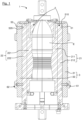
- FIG. 1 illustrates a device 1 according to the invention for manufacturing a plastic container by blowing or stretch-blow molding from a blank.
- Mold 2 comprises two half-molds, one half-mold of reference 21, and a second half-mold 22.
- the reference half-mold 21 and the second half-mold 22 are applied against each other and define between them a cavity with the imprint E of the container to be formed.
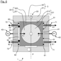
- the reference half-mold 21 and the second half-mold 22 also define a joint plane P (illustrated on the Figure 6 ) by bringing them into contact. More precisely, this joint plane P is defined at the level of the respective faces of the reference half-mold 21 and the second half-mold 22 which are in contact with each other during the blowing of the container.
- the reference half-mold 21 more precisely comprises a first half-shell 211 and a first shell support 212.
- the second half-mold 22 comprises a second half-shell 221 and a second shell support 222.
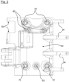
- the two supports 3 more specifically comprise a first support 31 and a second support 32.
- This first support 31 and this second support 32 are conventionally referred to as a bracket.
- the first support 31 and the second support 32 respectively carry the reference half-mold 21 and the second half-mold 22.
- first support 31 and the second support 32 encase the mold 2.
- the first support 31 and the second support 32 are designed to take up and distribute the blowing forces exerted inside the mold 2 during blowing.
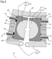
- first support 31 and the second support 32 are movable, by means of a hinge 33 between an open position ( Figure 3 ) and a closed position, illustrated by the figures 1 , 5 And 6 , positions in which mold 2 is also closed.
- the device 1 comprises means for locking the first support 31 and the second support 32 in the container blowing position.
- the device 1 has a locking and unlocking clearance between the reference half-mold 21 and the second half-mold 22 allowing the locking means to move from an unlocked state to a locked state, and vice versa.
- the device 1 also comprises means for compensating for a blowing pressure inside the mold 2.
- the compensation means use a fluid to compensate for the blowing pressure inside the mold 2.
- the compensation means make it possible to exert a compensation force F1 on the reference half-mold 21, and a compensation force F2 on the second half-mold 22.
- the reference half-mold 21 is movable relative to the first support 31.
- the reference half-mold 21 in particular has a clearance relative to the first support 31.
- the second half-mold 22 is movable relative to the second support 32, the second half-mold 22 thus having a clearance relative to the second support 32.
- the reference half-mold 21 has a compensation surface S1 which is defined by the first sealed chamber 41 interposed between the reference half-mold 21 and the first support 31.
- the second half-mold 22 has a compensation surface S2 defined by the second sealed chamber 42 interposed between the second half-mold 22 and the second support 32.
- the compensation surface S2 of the second half-mold 22 is greater than or equal to the compensation surface S1 of the reference half-mold 21, i.e. S2 ⁇ S1.
- the compensation surface S2 is strictly greater than the compensation surface S1, i.e. S2 > S1.
- the compensation surface S1 is advantageously symmetrical to the compensation surface S2. This is in particular a planar symmetry according to the joint plane P illustrated in the Figure 6 .
- the device 1 also comprises a first elastically deformable peripheral seal 51 as well as a second elastically deformable peripheral seal 52.
- the first peripheral seal 51 delimits the first sealed chamber 41 between the first support 31 and the reference half-mold 21.
- the second peripheral seal 52 delimits the second sealed chamber 42 between the second support 32 and the second half-mold 22.
- pressurized air is injected into the sealed chambers 41, 42, which causes an increase in the pressure therein.
- This pressure is capable of moving the half-molds 21, 22 away from each other and their supports 31, 32.
- the elastically deformable peripheral seals 51, 52 provide a sealed connection between each of the half-molds 21, 22 and their respective support 31, 32.
- the first peripheral seal 51 and the second peripheral seal 52 are advantageously lip seals which have a substantially U-shaped section.
- each peripheral seal 51, 52 is housed in a groove 510, 520 presented respectively by the reference half-mold 21 and by the second half-mold 22.
- the device 1 also comprises a mechanism for referential positioning of one of the half-molds, then designated by the expression reference half-mold 21, against at least one referential stop 61 carried by the support of the reference half-mold 21 while the second half-mold 22 is itself movable under the action of the pressurized fluid.
- the reference positioning mechanism prevents, during compensation, the pressurized fluid injected into the first sealed chamber 41 from managing to move the reference half-mold away from the reference stop(s) 61.
- the reference positioning mechanism thus more specifically comprises at least one reference stop 61 carried by the first support 31.
- the device 1 comprises three reference stops 61 carried by the first support 31.
- the device 1 also comprises additional stops 62 which limit the movement of the second half-mold 22 relative to the second support 32.
- the reference stops 61 and the additional stops 62 are more specifically screw stops which can be adjusted to modify the movement of the reference half-mold 21 and the second half-mold 22.
- the device 1 comprises means 43 for injecting a pressurized fluid into the sealed chambers 41, 42.
- the pressure P2 is strictly greater than the pressure P1.
- the pressure P2 is equal to the pressure P1.
- the holding means also comprise elastic return members, called first return members 71, of the reference half-mold 21 in a position pressed against its support.
- the first return members 71 comprise springs 710.
- the first return members 71 are calibrated so as to exert a return force E1.
- This return force E1 can for example be adjusted by the choice of a spring 710 with a suitable elastic return force.
- the device 1 comprises second return members 72 of the second half-mold 22 against its support 32.
- These second return members 72 are configured to exert a return force E2.
- the first support 31 has a similar design and an identical number of reference stops 61 and first return members 71.
- the return force E1 is greater than the return force E2.
- the first return members 71 tend to always keep the reference half-mold 21 pressing against the reference stops 61, and thus in a position pressed against its support 31.
- the device 1 allows the implementation of a method for manufacturing a container by blowing or stretch-blow molding from a plastic blank.
- This manufacturing process includes a step of compensating for a blowing pressure inside the mold.
- a pressurized fluid particularly air, is injected into the sealed chambers to exert a compensation force.
- a fluid is injected under a pressure P1 into the first sealed chamber 41, as well as a fluid under a pressure P2 into the sealed chamber 42.
- the reference half-mold 21 adopts a reference spatial position by resting against the reference stops 61 carried by the support of the reference half-mold 21 (the first support 31), while the second half-mold 22 is pressed against the reference half-mold 21.
- the first sealed chamber 41 and the second sealed chamber 42 are pressurized using the injection means 43.
- the reference half-mold 21 adopts its reference spatial position by resting against the reference stops 61.
- the second half-mold 22 is detached from the additional stops 62 under the effect of the compensation, and pressed against the reference half-mold 21.
- the adoption of the reference spatial position by the reference half-mold 21 during the compensation step can be obtained in different ways.
- the sum of the forces exerted on the reference half-mold 21 and the sum of the forces exerted on the second half-mold 22 have a difference such that the reference half-mold 21 is held in abutment against the reference stops 61.
- an identical compensation force F1, F2 is exerted for each half-mold 21, 22, and the return force E1 of the reference half-mold 21 in a position bearing against the reference stops 61 is exerted, this return force being distinct from the compensation forces.
- the return force E1 exerted by the first return members 71 is greater than the return force E2 exerted by the second return members 72.
- the compensation force F2 is strictly greater than the compensation force F1.
- the compensation forces F1, F2 then make it possible to maintain the reference half-mold 21 against the reference stops 61, while the second half-mold 22 is driven and pressed against the reference half-mold 21.
- This difference in compensation forces can in particular be obtained by means of the injection of a fluid, into the second sealed chamber 42, at a pressure P2 which is strictly greater than a pressure P1 of the fluid injected into the first sealed chamber 41.
- This difference in compensation force can also be obtained by injecting a fluid into the sealed chambers 41, 42 at an identical pressure P1, P2, with sealed chambers 41, 42 of different shape, and in particular with a compensation surface S2 of the second half-mold 22 greater than a compensation surface S1 of the reference half-mold 21.
- This objective is achieved by anticipating the injection of a fluid into the second sealed chamber 42 relative to the injection of the pressurized fluid into the first sealed chamber 41.
- This objective is also achieved with a restoring force E1 strictly greater than the restoring force E2.
- mold 2 is opened and receives a blank.
- the closing of the mold 2 is carried out by the passage of the first support 31 and the second support 32 from their open position to their closed position.
- the locking means ensure that the mold 2 does not open during blowing. This closing of the mold is facilitated by the first return members 71 and the second return members 72 which keep the half-molds pressed respectively against the reference stops 61 and the annex stops 62 of their respective support 31, 32.
- the injection means 43 are controlled so as to coordinate the pressure increase of the container in the mold 2 with that of the sealed chambers 41, 42.
- the compensation is then carried out symmetrically at the level of the two half-molds 21, 22.
- the blowing pressure inside the mold 2 is equal to the injection pressure of a pressurized fluid inside the first sealed chamber 41 and inside the second sealed chamber 42.
- the injection of air into the second sealed chamber 42 makes it possible to move the second half-mold 22 away from the second support 32, and thus to press the second half-mold 22 against the reference half-mold 21.
- the first sealed chamber 41 is not far from its support 31.
- the reference half-mold 21 remains in its reference spatial position, resting against the reference stops 61 carried by the first support 31.
- the pressure is released in the mold 2, and the air from the sealed chambers 41, 42 is evacuated.
- the first support 31 and the second support 32 then move from their closed position of the container to their open position to open the mold 2, and allow the extraction of the formed container, the start of a new cycle of forming a container.
Landscapes
- Engineering & Computer Science (AREA)
- Manufacturing & Machinery (AREA)
- Mechanical Engineering (AREA)
- Moulds For Moulding Plastics Or The Like (AREA)
- Blow-Moulding Or Thermoforming Of Plastics Or The Like (AREA)
Claims (11)
- Vorrichtung (1) zur Herstellung eines Behälters durch Blasformen oder Streckblasformen ausgehend von einem Vorformling aus Kunststoff, wobei die Vorrichtung Folgendes beinhaltet:- eine Form (2), die zwei Formhälften (21, 22) beinhaltet, die zusammen einen Abdruck (E) des zu bildenden Behälters definieren;- einen Träger (31, 32) für jede der Formhälften (21, 22), wobei jede Formhälfte (21, 22) zu ihrem Träger (31, 32) ein Spiel aufweist;- Mittel zum Ausgleichen eines Blasformdrucks innerhalb der Form (2);wobei die Ausgleichsmittel Folgendes beinhalten:- mindestens eine dichte Kammer (41, 42), die zwischen jeder Formhälfte (21, 22) und ihrem Träger (31, 32) eingefügt ist;- Mittel zum Einspritzen (43) eines Druckfluids in die dichten Kammern (41, 42);dadurch gekennzeichnet, dass sie Folgendes beinhaltet: einen Mechanismus zur Referenzpositionierung einer der Formhälften, als Referenzformhälfte (21) bezeichnet, an mindestens einem Referenzanschlag (61), der durch den Träger (31) der Referenzformhälfte (21) getragen wird, wobei der oder die Referenzanschläge (61) die Verschiebung der Referenzformhälfte (21) hin zu ihrem Träger (31) zu begrenzen suchen,und Mittel zum Halten der Referenzformhälfte (21) in Anlage an dem oder den Referenzanschlägen (61), während die andere der Formhälften, als zweite Formhälfte (22) bezeichnet, unter Einwirkung des Druckfluids beweglich ist.
- Vorrichtung (1) nach dem vorhergehenden Anspruch, dadurch gekennzeichnet, dass:- die Referenzformhälfte (21) eine Ausgleichsfläche (S1) aufweist, die durch die dichte Kammer (41) definiert wird, die zwischen der Referenzformhälfte (21) und ihrem Träger (31) eingefügt ist;- die zweite Formhälfte (22) eine Ausgleichsfläche (S2) aufweist, die durch die dichte Kammer (42) definiert wird, die zwischen der zweiten Formhälfte (22) und ihrem Träger (32) eingefügt ist;wobei S2 > S1.
- Vorrichtung (1) nach Anspruch 1, dadurch gekennzeichnet, dass:- die Referenzformhälfte (21) eine Ausgleichsfläche (S1) aufweist, die durch die dichte Kammer (41) definiert wird, die zwischen der Referenzformhälfte (21) und ihrem Träger (31) eingefügt ist;- die zweite Formhälfte (22) eine Ausgleichsfläche (S2) aufweist, die durch die dichte Kammer (42) definiert wird, die zwischen der zweiten Formhälfte (22) und ihrem Träger (32) eingefügt ist;wobei S2 = S1,und dass die Ausgleichsfläche (S1) der Referenzformhälfte (21) zu der Ausgleichsfläche (S2) der zweiten Formhälfte (22) symmetrisch ist.
- Vorrichtung (1) nach einem der vorhergehenden Ansprüche, dadurch gekennzeichnet, dass die Einspritzmittel (43) zu Folgendem konfiguriert sind:- Einspritzen eines Fluids mit einem ersten Druck (P1) in die dichte Kammer, als erste dichte Kammer (41) bezeichnet, die zwischen der Referenzformhälfte (21) und ihrem Träger (31) eingefügt ist;- Einspritzen eines Fluids mit einem zweiten Druck (P2) in die dichte Kammer, als zweite dichte Kammer (42) bezeichnet, die zwischen der zweiten Formhälfte (22) und ihrem Träger (32) eingefügt ist,wobei P2 > P1.
- Vorrichtung (1) nach einem der Ansprüche 1 bis 3, dadurch gekennzeichnet, dass die Einspritzmittel (43) zu Folgendem konfiguriert sind:- Einspritzen eines Fluids mit einem ersten Druck (P1) in die dichte Kammer, als erste dichte Kammer (41) bezeichnet, die zwischen der Referenzformhälfte (21) und ihrem Träger (31) eingefügt ist;- Einspritzen eines Fluids mit einem zweiten Druck (P2) in die dichte Kammer, als zweite dichte Kammer (42) bezeichnet, die zwischen der zweiten Formhälfte (22) und ihrem Träger (32) eingefügt ist,wobei P2 = P1.
- Vorrichtung (1) nach einem der vorhergehenden Ansprüche, dadurch gekennzeichnet, dass die Haltemittel mindestens ein elastisches Organ zum Zurückstellen, als erstes Rückstellorgan (71) bezeichnet, der Referenzformhälfte (21) in eine gegen ihren Träger (31) gedrückte Position beinhalten.
- Vorrichtung (1) nach dem vorhergehenden Anspruch, dadurch gekennzeichnet, dass sie mindestens ein elastisches Organ zum Zurückstellen, als zweites Rückstellorgan (72) bezeichnet, der zweiten Formhälfte (22) gegen ihren Träger (32) beinhaltet,
und dass:- das oder die ersten Rückstellorgane (71) eine Rückstellkraft (E1) ausüben;- das oder die zweiten Rückstellorgane (72) eine Rückstellkraft (E2) ausüben,wobei E1 > E2. - Verfahren zur Herstellung eines Behälters durch Blasformen oder Streckblasformen eines Vorformlings aus Kunststoff in einer Form (2), die zwei Formhälften (21, 22) beinhaltet, die jeweils durch einen Träger (31, 32) getragen werden, wobei für jede Formhälfte (21, 22) mindestens eine dichte Kammer (41, 42) zwischen der Formhälfte (21, 22) und ihrem Träger (31, 32) eingefügt ist,wobei das Verfahren einen Schritt des Ausgleichens eines Blasformdrucks innerhalb der Form (2) beinhaltet,wobei der Ausgleichsschritt darin besteht, ein Druckfluid in die dichten Kammern (41, 42) einzuspritzen, um eine Ausgleichskraft auszuüben, dadurch gekennzeichnet, dass während des Ausgleichsschritts eine der Formhälften, als Referenzformhälfte (21) bezeichnet, eine räumliche Referenzposition einnimmt, indem sie an mindestens einem Referenzanschlag (61), der von dem Träger (31) der Referenzformhälfte (21) getragen wird, anliegt, während die andere Formhälfte, als zweite Formhälfte (22) bezeichnet, gegen die Referenzformhälfte (21) gedrückt wird.
- Verfahren nach dem vorhergehenden Anspruch, dadurch gekennzeichnet, dass während des Ausgleichsschritts eine identische Ausgleichskraft (F1, F2) für jede Formhälfte (21, 22) ausgeübt wird und eine Kraft zum Zurückstellen (E1) der Referenzformhälfte (21) in eine an dem oder den Referenzanschlägen (61) anliegende Position ausgeübt wird, wobei sich die Rückstellkraft (E1) von den Ausgleichskräften (F1, F2) unterscheidet.
- Verfahren nach Anspruch 8, dadurch gekennzeichnet, dass während des Ausgleichsschritts:- eine Ausgleichskraft (F1) für die Referenzformhälfte (21) ausgeübt wird;- eine Ausgleichskraft (F2) für die zweite Formhälfte (22) ausgeübt wird,wobei F2 > F1.
- Verfahren nach dem vorhergehenden Anspruch, dadurch gekennzeichnet, dass während des Ausgleichsschritts:- ein Fluid mit einem Druck (P1) in die dichte Kammer, als erste dichte Kammer (41) bezeichnet, die zwischen der Referenzformhälfte (21) und ihrem Träger (31) eingefügt ist, eingespritzt wird;- ein Fluid mit einem Druck P2 in die dichte Kammer, als zweite dichte Kammer (42) bezeichnet, die zwischen der zweiten Formhälfte (22) und ihrem Träger (32) eingefügt ist, eingespritzt wird;wobei P2 > P1.
Applications Claiming Priority (2)
| Application Number | Priority Date | Filing Date | Title |
|---|---|---|---|
| FR2002643A FR3108268B1 (fr) | 2020-03-18 | 2020-03-18 | Dispositif pour la fabrication d’un récipient par soufflage ou étirage-soufflage |
| PCT/EP2021/056009 WO2021185647A1 (fr) | 2020-03-18 | 2021-03-10 | Dispositif et procédé pour la fabrication d'un recipient par soufflage ou etirage-soufflage |
Publications (2)
| Publication Number | Publication Date |
|---|---|
| EP4121271A1 EP4121271A1 (de) | 2023-01-25 |
| EP4121271B1 true EP4121271B1 (de) | 2025-04-30 |
Family
ID=70804781
Family Applications (1)
| Application Number | Title | Priority Date | Filing Date |
|---|---|---|---|
| EP21709726.0A Active EP4121271B1 (de) | 2020-03-18 | 2021-03-10 | Vorrichtung und verfahren zur herstellung eines behälters durch blasformen oder streckblasformen |
Country Status (3)
| Country | Link |
|---|---|
| EP (1) | EP4121271B1 (de) |
| FR (1) | FR3108268B1 (de) |
| WO (1) | WO2021185647A1 (de) |
Family Cites Families (5)
| Publication number | Priority date | Publication date | Assignee | Title |
|---|---|---|---|---|
| CH534044A (de) | 1970-06-08 | 1973-02-28 | Holstein & Kappert Maschf | Vorrichtung zum Ausformen thermoplastischen Materials mit gegeneinander bewegbaren Formhälften |
| FR2659265B1 (fr) | 1990-03-06 | 1992-06-26 | Sidel Sa | Procede de dispositif pour fabriquer des recipients en matieres thermoplastiques par soufflage ou etirage-soufflage. |
| FR2733176B1 (fr) | 1995-04-19 | 1997-06-27 | Sidel Sa | Dispositif pour fabriquer des recipients en une matiere thermoplastique par soufflage ou etirage-soufflage |
| DE102013104995A1 (de) * | 2013-05-15 | 2014-11-20 | Krones Ag | Blasformmaschine mit separater Druckkissenansteuerung |
| FR3038541B1 (fr) * | 2015-07-08 | 2017-07-21 | Sidel Participations | Dispositif de moulage pour une machine de fabrication de recipients en matiere thermoplastique |
-
2020
- 2020-03-18 FR FR2002643A patent/FR3108268B1/fr active Active
-
2021
- 2021-03-10 EP EP21709726.0A patent/EP4121271B1/de active Active
- 2021-03-10 WO PCT/EP2021/056009 patent/WO2021185647A1/fr not_active Ceased
Also Published As
| Publication number | Publication date |
|---|---|
| EP4121271A1 (de) | 2023-01-25 |
| WO2021185647A1 (fr) | 2021-09-23 |
| FR3108268B1 (fr) | 2024-01-12 |
| FR3108268A1 (fr) | 2021-09-24 |
Similar Documents
| Publication | Publication Date | Title |
|---|---|---|
| EP1216136B1 (de) | Blasformmaschine mit einem schliess- und verriegelungsmechanismus | |
| EP1315606B1 (de) | Giesseinheit mit einer membranbegrenzten ausgleichkammer, membran für eine solche einheit und eine maschine mit dieser einheit | |
| EP1998945A1 (de) | Spritz-/blasvorrichtung zur herstellung einer dünnen wandkomponente und entsprechendes verfahren | |
| EP3057767B1 (de) | Formeinheit zur herstellung von behältern mit einem kompensationsgreifer | |
| EP2070675B1 (de) | Gussform mit einer Verschlussvorrichtung | |
| EP2125331B1 (de) | Formvorrichtung zur herstellung von gefässen aus einem thermoplastischen material | |
| EP3587071B1 (de) | Formgusseinheit, die mit einem mobilen einsatz zur erstellung von boxen ausgestattet ist, der durch einen vom fluidkreislauf der boxen-erstellung abgeleiteten fluidkreislauf belüftet wird | |
| EP2938533A1 (de) | Fussboden aus kunststoff für ein kraftfahrzeug mit metallarmatureinsätzen | |
| FR2924974A1 (fr) | Moule pour la fabrication de recipients thermoplastiques et installation de soufflage ou d'etirage-soufflage equipee d'un tel moule | |
| EP4121271B1 (de) | Vorrichtung und verfahren zur herstellung eines behälters durch blasformen oder streckblasformen | |
| EP2111967B1 (de) | Vorrichtung zum Formgießen von Behältern einschließlich Mittel zum Regulieren der Volumenmaße des zu formenden Hohlraums | |
| FR2883794A1 (fr) | Dispositif de moulage ajustable en hauteur pour le moulage de recipients thermoplastiques de hauteurs diverses | |
| FR2963580A1 (fr) | Machine de formage equipee d'une unite de moulage comportant des moyens de compensation commandes par des vannes a actionnement automatique | |
| EP1169231B1 (de) | Kunststoffbehälter mit einer vertiefung insbesondere zum greifen, und verfahren zu seiner herstellung | |
| EP2682257A1 (de) | Herstellungsverfahren und -vorrichtung von Verbundmaterialteilen durch RTM | |
| FR3089446A1 (fr) | Dispositif pour la fabrication d’un récipient par soufflage ou étirage-soufflage | |
| EP3727795B1 (de) | Halbform mit zylindrischer montagefläche und herstellungsverfahren | |
| EP1912783A1 (de) | Verfahren zur herstellung eines teils mit einer von einem träger getragenen schaumstofflage | |
| EP3515683A1 (de) | Gussform mit dekompressionskanälen, die sich zu einer peripheren oberseite hin öffnen | |
| EP4228874B1 (de) | Form zur herstellung von kunststoffhohlkörpern | |
| WO2023126401A1 (fr) | Perfectionnement à une unité de moulage équipée d'un insert de boxage mobile | |
| FR2877259A1 (fr) | Dispositif de fabrication par moulage d'une enveloppe a soufflets comprenant un noyau devissable et des moyens de retenue de l'enveloppe, et procede correspondant | |
| FR3097793A1 (fr) | Moule d’injection | |
| FR2995243A1 (fr) | Moule d'injection pour bac de collecte, et procede d'injection associe. | |
| FR2947476A1 (fr) | Moule pour le moulage de pieces longitudinales en materiau polymere |
Legal Events
| Date | Code | Title | Description |
|---|---|---|---|
| STAA | Information on the status of an ep patent application or granted ep patent |
Free format text: STATUS: UNKNOWN |
|
| STAA | Information on the status of an ep patent application or granted ep patent |
Free format text: STATUS: THE INTERNATIONAL PUBLICATION HAS BEEN MADE |
|
| PUAI | Public reference made under article 153(3) epc to a published international application that has entered the european phase |
Free format text: ORIGINAL CODE: 0009012 |
|
| STAA | Information on the status of an ep patent application or granted ep patent |
Free format text: STATUS: REQUEST FOR EXAMINATION WAS MADE |
|
| 17P | Request for examination filed |
Effective date: 20220927 |
|
| AK | Designated contracting states |
Kind code of ref document: A1 Designated state(s): AL AT BE BG CH CY CZ DE DK EE ES FI FR GB GR HR HU IE IS IT LI LT LU LV MC MK MT NL NO PL PT RO RS SE SI SK SM TR |
|
| DAV | Request for validation of the european patent (deleted) | ||
| DAX | Request for extension of the european patent (deleted) | ||
| GRAP | Despatch of communication of intention to grant a patent |
Free format text: ORIGINAL CODE: EPIDOSNIGR1 |
|
| STAA | Information on the status of an ep patent application or granted ep patent |
Free format text: STATUS: GRANT OF PATENT IS INTENDED |
|
| RIC1 | Information provided on ipc code assigned before grant |
Ipc: B29C 49/78 20060101ALN20250205BHEP Ipc: B29C 49/12 20060101ALN20250205BHEP Ipc: B29C 49/48 20060101AFI20250205BHEP |
|
| GRAS | Grant fee paid |
Free format text: ORIGINAL CODE: EPIDOSNIGR3 |
|
| INTG | Intention to grant announced |
Effective date: 20250212 |
|
| GRAA | (expected) grant |
Free format text: ORIGINAL CODE: 0009210 |
|
| STAA | Information on the status of an ep patent application or granted ep patent |
Free format text: STATUS: THE PATENT HAS BEEN GRANTED |
|
| AK | Designated contracting states |
Kind code of ref document: B1 Designated state(s): AL AT BE BG CH CY CZ DE DK EE ES FI FR GB GR HR HU IE IS IT LI LT LU LV MC MK MT NL NO PL PT RO RS SE SI SK SM TR |
|
| REG | Reference to a national code |
Ref country code: CH Ref legal event code: EP Ref country code: GB Ref legal event code: FG4D Free format text: NOT ENGLISH |
|
| REG | Reference to a national code |
Ref country code: DE Ref legal event code: R096 Ref document number: 602021029975 Country of ref document: DE |
|
| P01 | Opt-out of the competence of the unified patent court (upc) registered |
Free format text: CASE NUMBER: APP_18393/2025 Effective date: 20250416 |
|
| REG | Reference to a national code |
Ref country code: IE Ref legal event code: FG4D Free format text: LANGUAGE OF EP DOCUMENT: FRENCH |
|
| REG | Reference to a national code |
Ref country code: NL Ref legal event code: MP Effective date: 20250430 |
|
| REG | Reference to a national code |
Ref country code: AT Ref legal event code: MK05 Ref document number: 1789646 Country of ref document: AT Kind code of ref document: T Effective date: 20250430 |
|
| PG25 | Lapsed in a contracting state [announced via postgrant information from national office to epo] |
Ref country code: PT Free format text: LAPSE BECAUSE OF FAILURE TO SUBMIT A TRANSLATION OF THE DESCRIPTION OR TO PAY THE FEE WITHIN THE PRESCRIBED TIME-LIMIT Effective date: 20250901 Ref country code: ES Free format text: LAPSE BECAUSE OF FAILURE TO SUBMIT A TRANSLATION OF THE DESCRIPTION OR TO PAY THE FEE WITHIN THE PRESCRIBED TIME-LIMIT Effective date: 20250430 Ref country code: FI Free format text: LAPSE BECAUSE OF FAILURE TO SUBMIT A TRANSLATION OF THE DESCRIPTION OR TO PAY THE FEE WITHIN THE PRESCRIBED TIME-LIMIT Effective date: 20250430 |
|
| REG | Reference to a national code |
Ref country code: LT Ref legal event code: MG9D |
|
| PG25 | Lapsed in a contracting state [announced via postgrant information from national office to epo] |
Ref country code: GR Free format text: LAPSE BECAUSE OF FAILURE TO SUBMIT A TRANSLATION OF THE DESCRIPTION OR TO PAY THE FEE WITHIN THE PRESCRIBED TIME-LIMIT Effective date: 20250731 Ref country code: NO Free format text: LAPSE BECAUSE OF FAILURE TO SUBMIT A TRANSLATION OF THE DESCRIPTION OR TO PAY THE FEE WITHIN THE PRESCRIBED TIME-LIMIT Effective date: 20250730 |
|
| PG25 | Lapsed in a contracting state [announced via postgrant information from national office to epo] |
Ref country code: NL Free format text: LAPSE BECAUSE OF FAILURE TO SUBMIT A TRANSLATION OF THE DESCRIPTION OR TO PAY THE FEE WITHIN THE PRESCRIBED TIME-LIMIT Effective date: 20250430 Ref country code: PL Free format text: LAPSE BECAUSE OF FAILURE TO SUBMIT A TRANSLATION OF THE DESCRIPTION OR TO PAY THE FEE WITHIN THE PRESCRIBED TIME-LIMIT Effective date: 20250430 |
|
| PG25 | Lapsed in a contracting state [announced via postgrant information from national office to epo] |
Ref country code: BG Free format text: LAPSE BECAUSE OF FAILURE TO SUBMIT A TRANSLATION OF THE DESCRIPTION OR TO PAY THE FEE WITHIN THE PRESCRIBED TIME-LIMIT Effective date: 20250430 |
|
| PG25 | Lapsed in a contracting state [announced via postgrant information from national office to epo] |
Ref country code: HR Free format text: LAPSE BECAUSE OF FAILURE TO SUBMIT A TRANSLATION OF THE DESCRIPTION OR TO PAY THE FEE WITHIN THE PRESCRIBED TIME-LIMIT Effective date: 20250430 |
|
| PG25 | Lapsed in a contracting state [announced via postgrant information from national office to epo] |
Ref country code: AT Free format text: LAPSE BECAUSE OF FAILURE TO SUBMIT A TRANSLATION OF THE DESCRIPTION OR TO PAY THE FEE WITHIN THE PRESCRIBED TIME-LIMIT Effective date: 20250430 |
|
| PG25 | Lapsed in a contracting state [announced via postgrant information from national office to epo] |
Ref country code: RS Free format text: LAPSE BECAUSE OF FAILURE TO SUBMIT A TRANSLATION OF THE DESCRIPTION OR TO PAY THE FEE WITHIN THE PRESCRIBED TIME-LIMIT Effective date: 20250731 |
|
| PG25 | Lapsed in a contracting state [announced via postgrant information from national office to epo] |
Ref country code: IS Free format text: LAPSE BECAUSE OF FAILURE TO SUBMIT A TRANSLATION OF THE DESCRIPTION OR TO PAY THE FEE WITHIN THE PRESCRIBED TIME-LIMIT Effective date: 20250830 |
|
| PG25 | Lapsed in a contracting state [announced via postgrant information from national office to epo] |
Ref country code: LV Free format text: LAPSE BECAUSE OF FAILURE TO SUBMIT A TRANSLATION OF THE DESCRIPTION OR TO PAY THE FEE WITHIN THE PRESCRIBED TIME-LIMIT Effective date: 20250430 |
|
| PG25 | Lapsed in a contracting state [announced via postgrant information from national office to epo] |
Ref country code: DK Free format text: LAPSE BECAUSE OF FAILURE TO SUBMIT A TRANSLATION OF THE DESCRIPTION OR TO PAY THE FEE WITHIN THE PRESCRIBED TIME-LIMIT Effective date: 20250430 Ref country code: SM Free format text: LAPSE BECAUSE OF FAILURE TO SUBMIT A TRANSLATION OF THE DESCRIPTION OR TO PAY THE FEE WITHIN THE PRESCRIBED TIME-LIMIT Effective date: 20250430 |
|
| PG25 | Lapsed in a contracting state [announced via postgrant information from national office to epo] |
Ref country code: CZ Free format text: LAPSE BECAUSE OF FAILURE TO SUBMIT A TRANSLATION OF THE DESCRIPTION OR TO PAY THE FEE WITHIN THE PRESCRIBED TIME-LIMIT Effective date: 20250430 |
|
| PG25 | Lapsed in a contracting state [announced via postgrant information from national office to epo] |
Ref country code: EE Free format text: LAPSE BECAUSE OF FAILURE TO SUBMIT A TRANSLATION OF THE DESCRIPTION OR TO PAY THE FEE WITHIN THE PRESCRIBED TIME-LIMIT Effective date: 20250430 |
|
| PG25 | Lapsed in a contracting state [announced via postgrant information from national office to epo] |
Ref country code: SK Free format text: LAPSE BECAUSE OF FAILURE TO SUBMIT A TRANSLATION OF THE DESCRIPTION OR TO PAY THE FEE WITHIN THE PRESCRIBED TIME-LIMIT Effective date: 20250430 |