EP3556515A1 - Reibungskupplungseinheit, werkzeug für den zusammenbau dieser einheit und zusammenbauverfahren, für das dieses werkzeug benutzt wird - Google Patents
Reibungskupplungseinheit, werkzeug für den zusammenbau dieser einheit und zusammenbauverfahren, für das dieses werkzeug benutzt wird Download PDFInfo
- Publication number
- EP3556515A1 EP3556515A1 EP19168324.2A EP19168324A EP3556515A1 EP 3556515 A1 EP3556515 A1 EP 3556515A1 EP 19168324 A EP19168324 A EP 19168324A EP 3556515 A1 EP3556515 A1 EP 3556515A1
- Authority
- EP
- European Patent Office
- Prior art keywords
- friction
- pressure plate
- clutch
- adhesive
- clutch assembly
- Prior art date
- Legal status (The legal status is an assumption and is not a legal conclusion. Google has not performed a legal analysis and makes no representation as to the accuracy of the status listed.)
- Withdrawn
Links
Images



Classifications
-
- F—MECHANICAL ENGINEERING; LIGHTING; HEATING; WEAPONS; BLASTING
- F16—ENGINEERING ELEMENTS AND UNITS; GENERAL MEASURES FOR PRODUCING AND MAINTAINING EFFECTIVE FUNCTIONING OF MACHINES OR INSTALLATIONS; THERMAL INSULATION IN GENERAL
- F16D—COUPLINGS FOR TRANSMITTING ROTATION; CLUTCHES; BRAKES
- F16D13/00—Friction clutches
- F16D13/58—Details
-
- B—PERFORMING OPERATIONS; TRANSPORTING
- B25—HAND TOOLS; PORTABLE POWER-DRIVEN TOOLS; MANIPULATORS
- B25B—TOOLS OR BENCH DEVICES NOT OTHERWISE PROVIDED FOR, FOR FASTENING, CONNECTING, DISENGAGING, OR HOLDING
- B25B27/00—Hand tools, specially adapted for fitting together or separating parts or objects whether or not involving some deformation, not otherwise provided for
- B25B27/0035—Hand tools, specially adapted for fitting together or separating parts or objects whether or not involving some deformation, not otherwise provided for for motor-vehicles
- B25B27/0064—Hand tools, specially adapted for fitting together or separating parts or objects whether or not involving some deformation, not otherwise provided for for motor-vehicles for assembling or disassembling clutches
-
- F—MECHANICAL ENGINEERING; LIGHTING; HEATING; WEAPONS; BLASTING
- F16—ENGINEERING ELEMENTS AND UNITS; GENERAL MEASURES FOR PRODUCING AND MAINTAINING EFFECTIVE FUNCTIONING OF MACHINES OR INSTALLATIONS; THERMAL INSULATION IN GENERAL
- F16D—COUPLINGS FOR TRANSMITTING ROTATION; CLUTCHES; BRAKES
- F16D2300/00—Special features for couplings or clutches
- F16D2300/12—Mounting or assembling
Definitions
- the invention relates to a friction clutch assembly comprising a clutch mechanism and a clutch disk, a tool suitable for assembling said assembly and a method of assembly using said tool.
- the transmission systems include, inter alia, a clutch mechanism and one or more friction discs.
- a conventional clutch mechanism generally comprises, on an axis of revolution, a cover in which is housed an annular diaphragm pivoting between an engaged position and a disengaged position so as to move a pressure plate.
- the lid, the diaphragm and the pressure plate are integral in rotation.
- the pressure plate urged by the diaphragm, is for clamping a clutch disk bearing friction linings on a reaction plate coaxial with the pressure plate and the clutch plate.
- the friction clutch disk is rotatably connected to the input shaft of the gearbox while the pressure plate is rotatably connected to the cover and the reaction plate connected to the drive shaft.
- the clamping of the friction clutch disc between the pressure and reaction plates corresponds to an engaged position which ensures the transmission of a torque between the motor shaft and the input shaft of the gearbox.
- Clutch mechanisms and friction clutch disks are usually packaged separately and delivered independently of each other on the assembly lines of automakers. It is then necessary to have in the assembly area different batches for the clutch mechanism and the clutch disk which must thus be mounted manually and in two successive operations on the flywheel.
- centering mandrel is generally made by injection molding of a plastic material and its dimensions are therefore not perfect, which can create a significant clearance centering on the hub and the centering bearing of the flywheel or motor
- a clutch mechanism and a friction clutch disc are combined as a unitary assembly on an auxiliary support tool, before mounting on the flywheel.
- This auxiliary tool comprises a holding zone receiving the clutch disc, means for retaining the clutch mechanism and the clutch disc coaxially on this tool and an appendage ensuring the centered positioning of the disc during assembly of the clutch disc. the whole on the flywheel.
- the assembly comprising the clutch mechanism and the clutch disc can be transported in the same container being supported by the auxiliary tool to the assembly line and can be bolted in a manner simple on the flywheel without using a centering chuck.
- this tool is not versatile because the centering means of the disk and the means for jointly retaining the mechanism and the disk depend on the respective structure of these components, in particular the shape of the annular diaphragm and therefore the type of clutch whose mounting is envisaged.
- the invention aims to remedy these technical problems by proposing an integral assembly in which the clutch mechanism and the friction disk are positioned, assembled and held in precise and centered relative positions during transport and then mounting on the steering wheel. motor and finally until the first engagement of the transmission system.
- a clutch assembly comprising, on the one hand, a clutch mechanism with a central axis of revolution formed of a cover provided with centering holes on a flywheel, a diaphragm and a pressure plate secured to rotation and, secondly, a friction disc having a central hub and carrying, at least on its face facing the pressure plate, peripheral friction linings, characterized in that the friction disk and the pressure plate are coaxially secured to one another by adhesive connecting elements.
- these connecting elements exert a radial cohesive force of between 5 and 50 N.
- the connecting elements are capable of breaking by releasing the clutch disk when a torque of less than or equal to 20 Nm is applied to the interface between the friction lining and the pressure plate.
- the adhesive connection elements cover between 0.1% and 10% of the friction face of the pressure plate and / or the face facing the peripheral friction lining.
- the connecting elements consist of at least one adhesive zone comprising a pressure-sensitive adhesive.
- the glue is an acrylate-based polymer.
- the adhesive zone is disposed on the friction face of the pressure plate of the clutch mechanism facing the peripheral friction linings of the friction disc.
- the clutch assembly comprises an adhesive zone located on the face of the friction disk disposed opposite the pressure plate.
- the adhesive zone may be applied on a single face or on both axially facing faces, respectively, of the clutch plate and the pressure plate.
- These adhesive zones may be in the form of circular lines or annular zones.
- the friction lining may comprise grooves extending radially on the friction face of the lining, said grooves having a width L.
- the diameter of the adhesive zone may be at least greater than 2 times the width L of the groove. In this way, it is possible to apply automated the adhesive area on the pressure plate and / or on the clutch disc without taking into consideration the position of the grooves.
- the diameter of the adhesive zone may be between 3 and 12 mm.
- the adhesive zones may be applied to the friction face of the pressure plate, near the inner periphery of the pressure plate. In this way, it is possible to limit the number of adhesive zones while guaranteeing the cohesive radial force of between 5 and 50 N and by reducing the breaking torque value applied to the interface between the friction linings and the plate. pressure.
- the adhesive zones may be applied together on an outer peripheral surface of the friction lining and on the periphery of the pressure plate. In this way, the adhesive zones are not in direct contact with the friction surface of the clutch disc and in some of the friction surface of the pressure plate and therefore do not risk to alter the coefficient of friction of the clutch disk. clutch assembly during the first starts of the vehicle.
- the adhesive surfaces are in the form of rectilinear or crossed glue lines.
- the clutch assembly of the invention comprises several ad hoc adhesive zones.
- the adhesive zone is formed of a double-sided adhesive annular ribbon or double-sided adhesive pellets.
- Another object of the invention is a tool for assembling a clutch assembly as defined above, characterized in that it comprises an extended base, upwards, on the one hand, by a clutch mechanism support base provided with peripheral clamping studs whose position coincides with that of the cover centering holes and, secondly, with an axial mandrel adapted to the central hub of the friction disc.
- the support base is formed of radial arms whose ends bear the locking studs of the cover.
- the mandrel has a smooth-walled lower portion forming an intermediate space with the central orifice of the diaphragm and an upper portion with a corrugated wall intended to slide axially in the hub of the disc. friction.
- the corrugated wall extends over the entire height of the mandrel, always leaving an interspace with the central orifice of the diaphragm
- Yet another object of the invention is a method of assembling a clutch assembly having the characteristics mentioned above by means of the tool described above, characterized in that the clutch mechanism is deposited on the base of the tool by arranging the pressure plate on the top and by introducing the wedges into the centering holes of the lid, adhesive binding elements are applied to the pressure plate and / or on one of the friction disc faces, the axial mandrel of the tool is engaged in the hub of the friction disc and the disc is pressed against the mechanism and the entire assembly is extracted from the tool by axial traction. along the mandrel.
- the connecting elements are applied on an area of between 0.1% and 10% of the friction face of the pressure plate and / or the friction lining.
- the invention enables easy and fast assembly and ensures accurate centering of the main components of the clutch of the transmission system in a single manual operation and without using any tool for the relative positioning of these components.
- the method and the tool of the invention apply equally well to a first assembly of the unit clutch element on the production line of a machine. vehicle manufacturer to a spare or maintenance operation at a garage.
- the invention also makes it possible to offer a significant gain in logistical cost because the unitary and integral clutch assembly groups together several components that were previously managed separately.
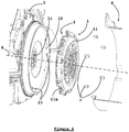
- the transmission system here comprises a conventional clutch mechanism 1 with axis of revolution X, provided, in particular, with a lid 11 , a pressure plate 13 and a diaphragm 12 interposed between the cover 11 and the pressure plate 13.
- the cover 11, the diaphragm 12 and the pressure plate 13 of the clutch mechanism 1 are secured in rotation with the flywheel 31 by means of screws 7.
- the lid 11 is provided, on its periphery, with centering orifices 11a cooperating with the mounting with pins 33 carried by the flywheel 31.
- the lid is also provided, on its periphery, screw holes 7, separate from the centering holes 11a.
- a clutch disc 2 provided with a central hub 20 is rotatably connected to the input shaft 41 of a gearbox 4 while the flywheel 31 is rotatably connected to the cover 11 via the 7.
- the clamping of the clutch disk 2 between the pressure plate 13 and the reaction plate 32 ensures the transmission of the engine torque to the gearbox 4.
- the flywheel 31 is, for example, a double-flywheel damper, as illustrated by the figure 1 .
- This flywheel can also be in the form of a rigid steering wheel.
- the diaphragm 12 is urged by a clutch pedal (not shown) to switch between a disengaged position and a engaged position.
- the diaphragm 12 axially displaces the pressure plate 13 which then clamps the clutch disk 2 on the reaction plate 32 of the flywheel 31 coaxial with the pressure plate 13 and the clutch plate 2.
- the clutch plate 2 carries, at least on its face facing the pressure plate 13, peripheral friction linings 21.
- the clutch mechanism 1 and the clutch disc 2 are independently manufactured components which are usually intended to be mounted, manually and in two successive operations, on the flywheel 31.
- the purpose of the invention is to simplify the assembly of these components by producing a clutch assembly in which these components 1, 2 are previously secured to one another in a separable manner in a position suitable for mounting both on the flywheel and on the gearbox.
- the friction disk 2 and the pressure plate 13 are assembled to each other coaxially and temporarily by adhesive connecting elements exerting a radial cohesive force of between 5 and 50 N.
- This cohesive force must be sufficient to maintain a firm and stable connection between the clutch mechanism 1 and the friction disc 2 during transport of the assembly thus formed and during the handling of this assembly for the assembly of the
- the radial cohesion force can be measured for example by blocking the clutch mechanism 1 and applying a radial force on the friction disk relative to the axis X.
- the adhesive bonding elements are capable of breaking by releasing the clutch disc when a torque of less than or equal to 20 Nm is applied to the interface between the friction liners 21 and the tray pressure 13. This breaking torque is lower than the minimum torque generated by the powertrain when it is at idle speed of the engine. The breaking torque is applied along the X axis.
- the adhesive connection elements are preferably made on the surfaces opposite the friction disc 2 and / or the pressure plate 13 of the clutch mechanism 1. Given the structure of the disc friction 2, these surfaces are necessarily located at the periphery of the disk 2 in the area where the liners 21 are located.
- the nature and the precise position of the connecting elements between these two components of the clutch are determined according to the engine torque to ensure that, during the first gearshift after the assembly of the clutch assembly on the flywheel, the link is broken immediately and the clutch disc can then rotate freely relative to the clutch mechanism.
- the assembly method of the invention provides for applying the adhesive connecting elements 6, 6a on a surface of between 0.1% and 10% of the surface of the friction face 13a of the pressure plate 13 and / or the friction lining 21.
- One embodiment of the clutch assembly of the invention consists in arranging the connecting elements on the friction face 13a of the pressure plate 13 and in the form of at least one adhesive zone 6 comprising a pressure-sensitive adhesive, as illustrated by the Figure 2B .
- the adhesive zone 6 is of annular shape.
- the diameter of the adhesive zone may be between 3 and 12 mm.
- the friction lining 21 comprises grooves extending radially on the friction face of the lining opening on the outer peripheral surface 21a of the friction lining, said grooves having a width L (visible on the figure 6 ).
- the diameter of the adhesive zone is at least greater than 2 times the width L of the groove. The adhesion of the clutch disk to the pressure plate 13 is thus improved.
- this adhesive is a polymer based on acrylate, sensitive to pressure and the setting is rapid at room temperature because the operating speed of the assembly lines and packaging is incompatible with an intermediate step of drying.
- glues could be used without departing from the scope of the invention.
- the clutch disc 2 is then applied to the friction face of the pre-glued pressure plate 13.
- the invention provides to further dispose an adhesive zone on the friction face of the friction lining 21 of the disc 2 disposed opposite the pressure plate 13.
- the clutch assembly comprises a plurality of spot adhesive zones or at least one adhesive zone formed of a double-sided adhesive annular ribbon 6a, as illustrated by FIG. figure 4 .
- the clutch disc 2 is then applied with the pre-glued friction face on the face 13a facing the pressure plate 13.
- the invention provides for applying the adhesive zones 6 together on an outer peripheral surface 21a of the friction lining and on the periphery of the pressure plate 13.
- the adhesive areas 6 are applied to the outer peripheral surface 13b of the pressure plate 13.
- the adhesive areas 6 are not in direct contact with the friction surfaces of the clutch plate and the pressure plate.
- the adhesive zones 6 are in particular applied to an area of the lining free padding of width L.
- adhesive bonding elements are deposited on the friction face 13a of the pressure plate 13 and on the friction face facing one of the friction linings 21 of the clutch disc 2.
- the invention also relates to a tool 5 for assembling the clutch assembly 1,2 previously described.
- This tool an embodiment of which is illustrated by the Figures 2A , 2B and 3A , 3B , comprises a base 51 extended, upwards, on the one hand, by a support base of the clutch mechanism 1 and, on the other hand, by an axial mandrel 53.
- the base is formed of radial arms 52, the ends of which bear peripheral studs 52a for wedging the cover 11 of the clutch mechanism 1.
- the angular and circumferential position of the pads 52a coincides with that of the centering holes 11a of the lid 11 which are intended to later cooperate with the pins 33, after assembly of the integral assembly 1, 2 on the flywheel 31.
- the mandrel 53 has, for its part, a lower portion 53a with a smooth wall forming a slight gap with the central orifice of the diaphragm 11 and an upper portion 53b with a corrugated wall intended to slide axially in the hub 20 of the friction disc 2 as illustrated by Figures 3A and 3B .
- the hub 20 comprises an inner groove adapted to the groove of the portion 53b of the mandrel 53.
- the corrugated wall extends over the entire height of the mandrel 53 while always providing an interspace with the central orifice 20 of the diaphragm 2.
- the assembly of the disk 2 and the clutch mechanism 1 is implemented according to the method described hereinafter using the tool 5.
- the clutch mechanism 1 is firstly deposited on the base 52 of the tool 5 by placing the pressure plate 13 upwards and by introducing the wedge pads 52a into the centering orifices 11a of the cover 11.
- the connecting elements are then applied here in the form of three points of glue 6 on the pressure plate 13, as illustrated by FIG. Figure 2B .
- An alternative embodiment may consist in arranging the connecting elements on one of the friction surfaces of the clutch plate 2 or both on the two opposite faces, respectively, of the disk 2 and the pressure plate 13 .
- the next step is to engage the axial mandrel 53 of the tool 5 in the hub 20 of the friction disc 2 and exerts a bearing on the disc to secure it to the mechanism 1 and lock it inside the lid 11.
- This support is intended to generate pressure on the adhesive areas between the surfaces in contact so as to promote the rapid setting of the adhesive.
- the integral unit 1, 2 is extracted from the tool 5 in one piece by axial traction along the mandrel 53.
Landscapes
- Engineering & Computer Science (AREA)
- General Engineering & Computer Science (AREA)
- Mechanical Engineering (AREA)
- Mechanical Operated Clutches (AREA)
Applications Claiming Priority (1)
| Application Number | Priority Date | Filing Date | Title |
|---|---|---|---|
| FR1853518A FR3080418B1 (fr) | 2018-04-20 | 2018-04-20 | Ensemble d’embrayage a friction, outil pour l’assemblage dudit ensemble et procede d’assemblage utilisant ledit outil |
Publications (1)
| Publication Number | Publication Date |
|---|---|
| EP3556515A1 true EP3556515A1 (de) | 2019-10-23 |
Family
ID=63080058
Family Applications (1)
| Application Number | Title | Priority Date | Filing Date |
|---|---|---|---|
| EP19168324.2A Withdrawn EP3556515A1 (de) | 2018-04-20 | 2019-04-10 | Reibungskupplungseinheit, werkzeug für den zusammenbau dieser einheit und zusammenbauverfahren, für das dieses werkzeug benutzt wird |
Country Status (2)
| Country | Link |
|---|---|
| EP (1) | EP3556515A1 (de) |
| FR (1) | FR3080418B1 (de) |
Cited By (1)
| Publication number | Priority date | Publication date | Assignee | Title |
|---|---|---|---|---|
| CN114193388A (zh) * | 2021-12-14 | 2022-03-18 | 苏州长风航空电子有限公司 | 弧形配重矩形叠片组件同轴装配工具及装配方法 |
Citations (6)
| Publication number | Priority date | Publication date | Assignee | Title |
|---|---|---|---|---|
| DE3742056A1 (de) * | 1986-12-17 | 1988-07-14 | Luk Lamellen & Kupplungsbau | Reibungskupplungseinheit |
| DE3814569A1 (de) * | 1988-04-29 | 1989-11-09 | Fichtel & Sachs Ag | Druckplatte mit fixiermitteln zur zentrierung der kupplungsscheibe |
| DE3916726A1 (de) * | 1988-05-24 | 1989-11-30 | Luk Lamellen & Kupplungsbau | Reibungskupplungseinheit sowie verfahren zu deren montage |
| FR2664003A1 (fr) * | 1990-06-27 | 1992-01-03 | Valeo | Procede d'assemblage d'un mecanisme d'embrayage centre et mecanisme d'embrayage assemble selon ledit procede. |
| FR2666760A1 (fr) * | 1990-09-17 | 1992-03-20 | Valeo | Ensemble unitaire d'embrayage, notamment pour vehicules automobiles. |
| DE202010011709U1 (de) * | 2010-08-23 | 2010-11-25 | Paschke, Uwe, Dipl.-Wirtsch.-Ing. | Vorrichtung zur Montage und Demontage einer Kraftfahrzeugkupplung |
-
2018
- 2018-04-20 FR FR1853518A patent/FR3080418B1/fr not_active Expired - Fee Related
-
2019
- 2019-04-10 EP EP19168324.2A patent/EP3556515A1/de not_active Withdrawn
Patent Citations (6)
| Publication number | Priority date | Publication date | Assignee | Title |
|---|---|---|---|---|
| DE3742056A1 (de) * | 1986-12-17 | 1988-07-14 | Luk Lamellen & Kupplungsbau | Reibungskupplungseinheit |
| DE3814569A1 (de) * | 1988-04-29 | 1989-11-09 | Fichtel & Sachs Ag | Druckplatte mit fixiermitteln zur zentrierung der kupplungsscheibe |
| DE3916726A1 (de) * | 1988-05-24 | 1989-11-30 | Luk Lamellen & Kupplungsbau | Reibungskupplungseinheit sowie verfahren zu deren montage |
| FR2664003A1 (fr) * | 1990-06-27 | 1992-01-03 | Valeo | Procede d'assemblage d'un mecanisme d'embrayage centre et mecanisme d'embrayage assemble selon ledit procede. |
| FR2666760A1 (fr) * | 1990-09-17 | 1992-03-20 | Valeo | Ensemble unitaire d'embrayage, notamment pour vehicules automobiles. |
| DE202010011709U1 (de) * | 2010-08-23 | 2010-11-25 | Paschke, Uwe, Dipl.-Wirtsch.-Ing. | Vorrichtung zur Montage und Demontage einer Kraftfahrzeugkupplung |
Cited By (2)
| Publication number | Priority date | Publication date | Assignee | Title |
|---|---|---|---|---|
| CN114193388A (zh) * | 2021-12-14 | 2022-03-18 | 苏州长风航空电子有限公司 | 弧形配重矩形叠片组件同轴装配工具及装配方法 |
| CN114193388B (zh) * | 2021-12-14 | 2024-05-31 | 苏州长风航空电子有限公司 | 弧形配重矩形叠片组件同轴装配工具及装配方法 |
Also Published As
| Publication number | Publication date |
|---|---|
| FR3080418B1 (fr) | 2021-01-22 |
| FR3080418A1 (fr) | 2019-10-25 |
Similar Documents
| Publication | Publication Date | Title |
|---|---|---|
| EP2990678B1 (de) | Kupplungsvorrichtung für kraftfahrzeug | |
| EP3366938B1 (de) | Elastische rückholvorrichtung für nasskupplungsmechanismus, und nasskupplung, die eine solche elastische rückholvorrichtung umfasst | |
| EP3252333B1 (de) | Axiales einrastsystem für einen kupplungsmechanismus | |
| FR2683875A1 (fr) | Embrayage ayant des anneaux rotatifs de friction, volant et plateau de pression a y utiliser. | |
| EP2960537A1 (de) | Kupplungsscheibe | |
| EP3580469A1 (de) | Kupplungsträger | |
| FR3081952A1 (fr) | Porte-disque assemble et mecanisme d'embrayage humide comprenant ce porte-disque assemble | |
| FR2736112A1 (fr) | Ensemble formant disque amortisseur, notamment pour un disque d'embrayage | |
| FR3080418A1 (fr) | Ensemble d’embrayage a friction, outil pour l’assemblage dudit ensemble et procede d’assemblage utilisant ledit outil | |
| WO2013104869A1 (fr) | Procédé de réalisation d'une garniture de friction d'embrayage | |
| FR2830480A1 (fr) | Dispositif d'aide au montage/centrage d'un ensemble a plateaux de pression d'un embrayage multiple | |
| EP3245416B1 (de) | Verschleisseinstellungsmechanismus für eine kupplungsvorrichtung, insbesondere für kraftfahrzeuge | |
| FR3073912B1 (fr) | Sous-ensemble de mecanisme d’embrayage et mecanisme d’embrayage normalement ouvert comprenant ce sous-ensemble | |
| WO2015180778A1 (fr) | Dispositif d'embrayage, notamment pour vehicule automobile | |
| EP3728890A1 (de) | Zweiteiliger kolben, wobei der kolben zur integration in einen kupplungsmechanismus bestimmt ist | |
| FR3038949A1 (fr) | Double embrayage, notamment pour vehicule automobile | |
| FR2646482A1 (fr) | Embrayage, notamment pour vehicule automobile | |
| WO2020002367A1 (fr) | Porte-disque assemble et mecanisme d'embrayage humide comprenant ce porte-disque assemble | |
| FR2606108A1 (fr) | Ensemble elastique unitaire a pieces globalement annulaires et applications, notamment poulie de variateur de vitesse et mecanisme d'embrayage comportant un tel ensemble elastique unitaire | |
| EP4193074A1 (de) | Drehmomentlösekupplung für ein hybridgetriebe | |
| FR2955634A1 (fr) | Embrayage comportant un mecanisme a diaphragme perfectionne destine notamment a commander un dispositif accessoire de l'embrayage. | |
| WO2020260184A1 (fr) | Mecanisme a double embrayage humide comprenant un porte-disques assemble | |
| FR3031775A1 (fr) | Mecanisme de rattrapage d'usure pour un dispositif d'embrayage, notamment pour vehicule automobile | |
| FR3031778A1 (fr) | Mecanisme de rattrapage d'usure pour un dispositif d'embrayage, notamment pour vehicule automobile | |
| FR2947317A1 (fr) | Systeme de transmission comportant un module integrant un mecanisme a double embrayage et son dispositif de commande |
Legal Events
| Date | Code | Title | Description |
|---|---|---|---|
| PUAI | Public reference made under article 153(3) epc to a published international application that has entered the european phase |
Free format text: ORIGINAL CODE: 0009012 |
|
| 17P | Request for examination filed |
Effective date: 20190410 |
|
| AK | Designated contracting states |
Kind code of ref document: A1 Designated state(s): AL AT BE BG CH CY CZ DE DK EE ES FI FR GB GR HR HU IE IS IT LI LT LU LV MC MK MT NL NO PL PT RO RS SE SI SK SM TR |
|
| AX | Request for extension of the european patent |
Extension state: BA ME |
|
| GRAP | Despatch of communication of intention to grant a patent |
Free format text: ORIGINAL CODE: EPIDOSNIGR1 |
|
| STAA | Information on the status of an ep patent application or granted ep patent |
Free format text: STATUS: GRANT OF PATENT IS INTENDED |
|
| INTG | Intention to grant announced |
Effective date: 20200714 |
|
| 18D | Application deemed to be withdrawn |
Effective date: 20201126 |