EP3555937B1 - Verfahren und system zur herstellung einer batteriezelle - Google Patents
Verfahren und system zur herstellung einer batteriezelle Download PDFInfo
- Publication number
- EP3555937B1 EP3555937B1 EP17797643.8A EP17797643A EP3555937B1 EP 3555937 B1 EP3555937 B1 EP 3555937B1 EP 17797643 A EP17797643 A EP 17797643A EP 3555937 B1 EP3555937 B1 EP 3555937B1
- Authority
- EP
- European Patent Office
- Prior art keywords
- battery cell
- housing
- rotation
- electrolyte
- axis
- Prior art date
- Legal status (The legal status is an assumption and is not a legal conclusion. Google has not performed a legal analysis and makes no representation as to the accuracy of the status listed.)
- Not-in-force
Links
Images



Classifications
-
- H—ELECTRICITY
- H01—ELECTRIC ELEMENTS
- H01G—CAPACITORS; CAPACITORS, RECTIFIERS, DETECTORS, SWITCHING DEVICES, LIGHT-SENSITIVE OR TEMPERATURE-SENSITIVE DEVICES OF THE ELECTROLYTIC TYPE
- H01G9/00—Electrolytic capacitors, rectifiers, detectors, switching devices, light-sensitive or temperature-sensitive devices; Processes of their manufacture
- H01G9/004—Details
- H01G9/022—Electrolytes; Absorbents
- H01G9/035—Liquid electrolytes, e.g. impregnating materials
-
- H—ELECTRICITY
- H01—ELECTRIC ELEMENTS
- H01M—PROCESSES OR MEANS, e.g. BATTERIES, FOR THE DIRECT CONVERSION OF CHEMICAL ENERGY INTO ELECTRICAL ENERGY
- H01M10/00—Secondary cells; Manufacture thereof
- H01M10/04—Construction or manufacture in general
- H01M10/0404—Machines for assembling batteries
-
- H—ELECTRICITY
- H01—ELECTRIC ELEMENTS
- H01M—PROCESSES OR MEANS, e.g. BATTERIES, FOR THE DIRECT CONVERSION OF CHEMICAL ENERGY INTO ELECTRICAL ENERGY
- H01M50/00—Constructional details or processes of manufacture of the non-active parts of electrochemical cells other than fuel cells, e.g. hybrid cells
- H01M50/60—Arrangements or processes for filling or topping-up with liquids; Arrangements or processes for draining liquids from casings
- H01M50/609—Arrangements or processes for filling with liquid, e.g. electrolytes
-
- H—ELECTRICITY
- H01—ELECTRIC ELEMENTS
- H01M—PROCESSES OR MEANS, e.g. BATTERIES, FOR THE DIRECT CONVERSION OF CHEMICAL ENERGY INTO ELECTRICAL ENERGY
- H01M50/00—Constructional details or processes of manufacture of the non-active parts of electrochemical cells other than fuel cells, e.g. hybrid cells
- H01M50/60—Arrangements or processes for filling or topping-up with liquids; Arrangements or processes for draining liquids from casings
- H01M50/609—Arrangements or processes for filling with liquid, e.g. electrolytes
- H01M50/627—Filling ports
-
- H—ELECTRICITY
- H01—ELECTRIC ELEMENTS
- H01G—CAPACITORS; CAPACITORS, RECTIFIERS, DETECTORS, SWITCHING DEVICES, LIGHT-SENSITIVE OR TEMPERATURE-SENSITIVE DEVICES OF THE ELECTROLYTIC TYPE
- H01G11/00—Hybrid capacitors, i.e. capacitors having different positive and negative electrodes; Electric double-layer [EDL] capacitors; Processes for the manufacture thereof or of parts thereof
- H01G11/54—Electrolytes
- H01G11/58—Liquid electrolytes
-
- H—ELECTRICITY
- H01—ELECTRIC ELEMENTS
- H01G—CAPACITORS; CAPACITORS, RECTIFIERS, DETECTORS, SWITCHING DEVICES, LIGHT-SENSITIVE OR TEMPERATURE-SENSITIVE DEVICES OF THE ELECTROLYTIC TYPE
- H01G13/00—Apparatus specially adapted for manufacturing capacitors; Processes specially adapted for manufacturing capacitors not provided for in groups H01G4/00 - H01G11/00
- H01G13/04—Drying; Impregnating
-
- H—ELECTRICITY
- H01—ELECTRIC ELEMENTS
- H01M—PROCESSES OR MEANS, e.g. BATTERIES, FOR THE DIRECT CONVERSION OF CHEMICAL ENERGY INTO ELECTRICAL ENERGY
- H01M50/00—Constructional details or processes of manufacture of the non-active parts of electrochemical cells other than fuel cells, e.g. hybrid cells
- H01M50/70—Arrangements for stirring or circulating the electrolyte
-
- Y—GENERAL TAGGING OF NEW TECHNOLOGICAL DEVELOPMENTS; GENERAL TAGGING OF CROSS-SECTIONAL TECHNOLOGIES SPANNING OVER SEVERAL SECTIONS OF THE IPC; TECHNICAL SUBJECTS COVERED BY FORMER USPC CROSS-REFERENCE ART COLLECTIONS [XRACs] AND DIGESTS
- Y02—TECHNOLOGIES OR APPLICATIONS FOR MITIGATION OR ADAPTATION AGAINST CLIMATE CHANGE
- Y02E—REDUCTION OF GREENHOUSE GAS [GHG] EMISSIONS, RELATED TO ENERGY GENERATION, TRANSMISSION OR DISTRIBUTION
- Y02E60/00—Enabling technologies; Technologies with a potential or indirect contribution to GHG emissions mitigation
- Y02E60/10—Energy storage using batteries
-
- Y—GENERAL TAGGING OF NEW TECHNOLOGICAL DEVELOPMENTS; GENERAL TAGGING OF CROSS-SECTIONAL TECHNOLOGIES SPANNING OVER SEVERAL SECTIONS OF THE IPC; TECHNICAL SUBJECTS COVERED BY FORMER USPC CROSS-REFERENCE ART COLLECTIONS [XRACs] AND DIGESTS
- Y02—TECHNOLOGIES OR APPLICATIONS FOR MITIGATION OR ADAPTATION AGAINST CLIMATE CHANGE
- Y02P—CLIMATE CHANGE MITIGATION TECHNOLOGIES IN THE PRODUCTION OR PROCESSING OF GOODS
- Y02P70/00—Climate change mitigation technologies in the production process for final industrial or consumer products
- Y02P70/50—Manufacturing or production processes characterised by the final manufactured product
Definitions
- the present invention relates to a method and a system for producing a battery cell according to the preamble of the independent claims.
- the US 2013/0065111 A1 shows an apparatus and a method for improved distribution of electrolyte in a secondary battery.
- the secondary battery is oscillated and rotated around its central axis.
- JPH06 1692 B2 relates to a method for filling a battery cell (5) with an electrolyte, the battery cell (5) being rotated about an axis of rotation (8) and the electrolyte being introduced into the battery cell by means of a centrifugal force generated by the rotation (cf. fig.3 ).
- EP 0 756 342 A1 shows a device for filling a battery with an electrolyte, the device having a main body (230) and a receiving device (210) with two battery cell housings (60).
- JP H08 7879 A discloses a device for filling a battery with an electrolyte.
- the device is operated in such a way that at least one battery (B) is rotated around an axis of rotation (1) (cf. fig. 1 and 3rd ).
- Battery systems are used both in stationary applications, such as wind turbines or solar energy systems, and in motor vehicles, such as hybrid vehicles or electric vehicles, or in electronic devices such as laptops or cell phones.
- the essence of the invention is that the electrolyte is introduced into the housing and the battery cell is rotated to wet the electrode arrangement with the electrolyte.
- the background to the invention is that a centrifugal force acts on the electrolyte due to the rotation. This centrifugal force pushes the electrolyte toward a bottom portion of the case. Capillary forces cause the electrolyte to penetrate the electrode arrangement and wet it.
- an improved wetting of the electrode arrangement with electrolyte is brought about compared to a battery cell which is not rotated.
- the housing can be made thinner and easier than with a battery cell into which the electrolyte is introduced by means of pressure.
- the battery cell in a second rotating step, is rotated by 160 ° to 200 °, in particular 180 °, compared to the method step of filling with electrolyte, and then stored in this position.
- the advantage here is that the electrolyte, due to the force of gravity, which acts in the opposite direction as during filling, flows in the opposite direction as during filling.
- capillary forces act on the electrolyte, causing it to penetrate Effect electrolytes in the electrode arrangement and their wetting with electrolyte in a region of the electrode arrangement adjacent to the opening.
- the electrolyte flows in the direction of gravity to the opening during storage.
- a wetted area of the electrode arrangement is thus enlarged, since the electrolyte flows in the opposite direction to that during filling.
- the opening of the housing is closed in a liquid-tight manner with a closure means, in particular a stopper or a metal band, in particular releasably. This prevents the electrolyte from splashing out of the housing during the second rotating step and / or from flowing out of the housing during storage.
- the closure means is removed from the housing and excess electrolyte is drained from the battery cell.
- the excess electrolyte can be reused for the production of another battery cell.
- the battery cell is subsequently sealed, in particular by means of a pressure compensation valve.
- the pressure compensation valve is only connected to the battery cell after the turning steps. Inadvertent triggering of the pressure compensation valve during one of the rotary steps can thus be avoided.
- the pressure equalization valve does not have any previous damage from the manufacturing process of the battery cell when it is put into operation.
- further electrolyte is filled into the battery cell before the second turning step. This enables the electrolyte to be metered in a targeted manner during the process. The amount of excess electrolyte can be reduced.
- the opening is not closed in the first turning step. This enables pressure to be equalized in the interior of the housing during the first turning step. Gases produced during activation of the battery cell can escape through the opening, so that an explosion of the battery cell can be prevented. As a result, the battery can be made compact, since there is no additional Space is to be provided in the housing for these gases. An additional work step for opening and degassing the battery cell can be saved.
- the electrolyte when the battery cell is being filled, the electrolyte flows from the opening in the direction of gravity into the housing.
- the advantage here is that the electrolyte flows into the housing at normal pressure.
- the pressure load on the housing of the battery cell is low.
- the housing is compact and easy to implement.
- the axis of rotation is preferably spaced from the battery cell.
- a holding means can be arranged between the battery cell and a shaft rotating about the axis of rotation for connecting the battery cell to the shaft.
- a plurality of battery cells can advantageously be rotated about the axis of rotation at the same time.
- a surface of the housing having the opening has the shortest distance between the housing and the axis of rotation.
- the opening is advantageously arranged in the center of rotation of the battery cell, so that the electrolyte is moved away from the opening by means of the centrifugal force. Leakage of electrolyte from the battery cell can thus be avoided.
- the surface preferably touches the axis of rotation at least partially.
- the electrolyte is moved away from the opening by means of the centrifugal force. Leakage of electrolyte from the battery cell can be avoided.
- the axis of rotation is oriented transversely to the direction of gravity.
- the battery cell thus performs a rollover about its latitude axis during the first rotation step.
- the gravitational force temporarily acts in the same direction as the centrifugal force, so that the gravitational force and centrifugal force temporarily reinforce each other.
- the battery cell is deflected in a direction transverse to the axis of rotation during the first rotation step.
- the battery cell is advantageously connected pivotably to a shaft rotating about the axis of rotation. If the axis of rotation is aligned parallel to the direction of gravity, the centrifugal force acts transversely to the direction of gravity and steers it Battery cell off.
- the battery cell is advantageously pivotably connected to the shaft in the region of the opening, so that the battery cell is essentially deflected around the opening.
- the invention is based on a system for producing a battery cell, in particular by means of a method as described above or according to one of the claims relating to the method.
- the essence of the invention is that the system has a battery cell and a holding means, the battery cell being connectable to a rotatably mounted shaft of a rotary motor by means of the holding means.
- the background to the invention is that the battery cell can be detachably connected to the rotatably mounted shaft in a simple manner.
- an electrolyte arranged in the battery cell can be evenly distributed in an electrode arrangement of the battery cell by means of a rotation, in particular by more than 360 °.
- the battery cell has a housing with a circumferential groove, the holding means having a recess, the housing and the holding means being connectable by means of the groove and the recess.
- the housing and the holding means can advantageously be connected to one another in a form-fitting manner.
- the groove is preferably designed in a step-like manner, the housing tapping in a step-like manner towards a side surface of the housing, the holding means having a cavity in which the battery cell is at least partially accommodated.
- the advantage here is that the holding means holds and protects the battery cell, since the holding means at least partially surrounds the battery cell.
- the recess and the groove advantageously have an identical cross section.
- the holding means and the housing can thus be plugged together in that a step-like tapered end region of the housing is inserted into the recess in the holding means.
- the housing has a circumferential projection, wherein the retaining means can be clip-connected to the housing by means of the projection, the retaining means being elastically deformable.
- the holding means can be elastically deformed in the transverse direction to the centrifugal force occurring during rotation. The housing can thus be securely and detachably connected to the holding means.
- the battery cell 1 is shown in a sectional view.
- the battery cell 1 has a housing 2 and an electrode arrangement 3.
- the electrode arrangement 3 is arranged in the interior of the housing 2.
- the electrode arrangement 3 is arranged at least partially at a distance from the housing 2, so that a first spatial region 9 is arranged between the housing 2 and the electrode arrangement 3.
- the first spatial region 9 preferably completely surrounds the electrode arrangement 3.
- a battery cell is understood here to mean, for example, a rechargeable cell of a rechargeable battery, in particular an electrochemical battery cell.
- the battery cell can be implemented as a lithium-based battery cell, in particular a lithium-ion battery cell.
- the battery cell is designed as a lithium polymer battery cell or a nickel-metal hydride battery cell or a lead-acid battery cell or a lithium-air battery cell or a lithium-sulfur battery cell.
- the housing 2 has an opening 6.
- the opening 6 of the housing 2 can be connected to a valve 5 of an electrolyte tank.
- the housing 2 can thus be filled with an electrolyte 7 by means of the opening 6 and the valve 5.
- the battery cell 1 is arranged in the gravitational direction in such a way that the opening 6 of the housing 2 is arranged at the highest point of the housing 2.
- the electrolyte 7 flows along the first spatial area 9 and wets a first section 4 'of the electrode arrangement 3 adjoining the first spatial area 9
- the electrolyte 7 collects on a bottom section 10 of the housing 2, the bottom section 10 being the section of the housing 2 that is furthest away from the opening 6 in the direction of gravity.
- a fill level 8 of the electrolyte 7 is highest on the wall of the housing 2 and decreases towards the center of the housing 2.
- the electrode arrangement 3 has a second section 4 which is wetted with less electrolyte 7 than the first section 4 '.
- the second section 4 is in the first Method step at a greater distance from the bottom section 10 of the housing 2 than from the opening 6.
- the direction of gravitation is understood to mean the direction in which the gravitational force acts.
- Figure 2 shows the battery cell 1, which is arranged rotatably about an axis of rotation 12.
- the axis of rotation 12 is oriented transversely to the direction of gravity.
- a distance between the opening 6 and the axis of rotation 12 is the shortest distance between the housing 2 and the axis of rotation 12.
- the opening 6 extends in a surface of the housing 2 parallel to the axis of rotation 12, in particular with the axis of rotation 12 touching the opening 6.
- the battery cell 1 is rotated about the axis of rotation 12 in a first rotational step, in particular rotated by several revolutions, in particular at a fixed frequency.
- a centrifugal force 13 acts on the electrolyte 7, which is oriented transversely to the axis of rotation 12.
- the centrifugal force 13 presses the electrolyte 7 in the housing 2 towards the bottom section 10.
- Capillary forces 11 act transversely to the centrifugal force 13 from the wall of the housing 2 into the electrode arrangement 3.
- the first section 4 ′ of the electrode arrangement 3 increases in size from the bottom section 10 in the opposite direction to the centrifugal force 13.
- the second section 4 of the electrode arrangement 3 is reduced in size, with a center of gravity of the second section 4 shifting towards the opening 6.
- the battery cell 1 is preferably unlocked during the first turning step.
- the battery cell 1 is reconnected to the valve 5 and filled with further electrolyte 7.
- Fig. 3 the battery cell 1 is shown, the opening 6 of which has been closed by means of a closure means 20, in particular a releasable closure means, preferably a stopper or a metal band, and which in a third method step in a second rotating step by 160 ° to 200 °, preferably 180 °, in particular upside down, rotated and then stored.
- a closure means 20 in particular a releasable closure means, preferably a stopper or a metal band
- a third method step in a second rotating step by 160 ° to 200 °, preferably 180 °, in particular upside down, rotated and then stored.
- the bottom section 10 is the highest area of the housing in the gravitational direction.
- the gravitational force is therefore oriented from the bottom section 10 towards the opening 6.
- Capillary forces 21 act against the force of gravity.
- the electrode arrangement 3 is wetted with electrolyte 7 from the opening 6 towards the bottom section 10.
- the first section 4 ′ of the electrode arrangement 3
- the closure means 20 is preferably removed after the third method step and excess electrolyte 7 is drained from the battery cell 1.
- the battery cell 1 is then sealed, in particular by means of a pressure compensation valve.
- the battery cell is pivotably connected to a shaft that can be rotated about the axis of rotation.
- the axis of rotation of the rotatable shaft is aligned parallel to the direction of gravity.
- the centrifugal force deflects the battery cell transversely to the direction of gravity.
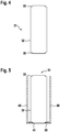
- FIG. 4 shows a first embodiment of a battery cell 31 of a system according to the invention for producing a battery cell.
- the first exemplary embodiment of the battery cell 31 has a housing 32.
- the housing 32 is essentially cylindrical or cuboid and has at least one circumferential groove (30, 33).
- the groove (30, 33) is arranged at an end region of the housing 32.
- the housing 32 preferably has two grooves (30, 33) which are arranged on two opposite end regions of the housing 32.
- the respective groove (30, 33) is preferably designed as a step in the housing 32.
- the diameter or a side length of the housing 32 tapers in a step-like manner towards the end of the housing 32.
- a first embodiment of a holding means 40 of the system according to the invention for producing a battery cell is shown.
- the holding means 40 is designed as a hollow cylinder or hollow cuboid and has a recess 41 on one side surface.
- the recess 41 is here advantageously dimensioned such that the housing 32 of the battery cell 31 can be inserted into the recess 41 up to the step of the groove (30, 33).
- the housing 32 can thus be connected to the holding means 40 in a form-fitting manner.
- a side surface of the holding means 40 opposite the recess 41 is designed to be open.
- the battery cell 31 can be inserted into the holding means 40 through this side surface of the holding means 40.
- the battery cell 31 can be connected to a rotatably mounted shaft of a rotary motor.
- the axis of rotation of the shaft is arranged at a distance from the center of gravity of the battery cell 31, in particular arranged at a distance from the battery cell 31.
- the axis of rotation contacts a side surface of the housing 32.
- two or more battery cells 31 can be connected to the shaft, the axis of rotation being arranged between the battery cells 31 in a direction transverse to the axis of rotation.
- FIG. 6 shows a second embodiment of a battery cell 51 of a system according to the invention for producing a battery cell.
- the second exemplary embodiment of the battery cell 51 has a housing 52.
- the housing 52 is essentially cylindrical or cuboid and has a circumferential groove 50.
- the groove 50 is arranged at an end region of the housing 52.
- the groove 50 is arranged at a distance from a side surface of the end region of the housing 52.
- the distance between the groove 50 and the side surface is smaller than the smallest side length of the housing 52.
- a projection 53 is arranged between the groove 50 and the side surface of the housing.
- a second embodiment of a holding means 60 of the system according to the invention for producing a battery cell is shown.
- the holding means 60 is designed as a hollow cylinder or hollow cuboid and has a recess 61 on one side surface.
- the recess 61 is advantageously dimensioned in such a way that the housing 32 of the battery cell 51 can be introduced with the groove 50 into the recess 61.
- the housing 52 can thus be connected to the holding means 60 in a form-fitting manner.
- the holding means 60 is preferably designed to be elastically deformable, so that the housing 52 can be clipped into the holding means 60.
- the holding means 60 is elastically deformed in order to guide it over the projection 53 and then clips into the groove 50.
- the battery cell 51 can be connected to a rotatably mounted shaft of a rotary motor.
- the axis of rotation of the shaft is arranged at a distance from the center of gravity of the battery cell 51, in particular arranged at a distance from the battery cell 51.
- the axis of rotation contacts a side surface of the housing 52.
- two or more battery cells 51 can be connected to the shaft, the axis of rotation being arranged between the battery cells 51 in a direction transverse to the axis of rotation.
Landscapes
- Chemical & Material Sciences (AREA)
- Chemical Kinetics & Catalysis (AREA)
- Electrochemistry (AREA)
- General Chemical & Material Sciences (AREA)
- Engineering & Computer Science (AREA)
- Manufacturing & Machinery (AREA)
- Power Engineering (AREA)
- Microelectronics & Electronic Packaging (AREA)
- Sealing Battery Cases Or Jackets (AREA)
- Filling, Topping-Up Batteries (AREA)
- Hybrid Cells (AREA)
- Battery Mounting, Suspending (AREA)
Description
- Die vorliegende Erfindung bezieht sich auf ein Verfahren und ein System zur Herstellung einer Batteriezelle gemäß dem Oberbegriff der unabhängigen Patentansprüche.
- Die
US 2013/0065111 A1 zeigt eine Vorrichtung und ein Verfahren zur verbesserten Verteilung von Elektrolyt in einer Sekundärbatterie. Dabei wird die Sekundärbatterie oszilliert und um ihre Mittelachse rotiert. - In der
US 2013/0244095 A1 ist ein Entgasungsverfahren für eine Sekundärbatterie mittels Zentrifugalkraft gezeigt.JPH06 1692 B2 fig.3 ).EP 0 756 342 A1 zeigt eine Vorrichtung zur Befüllung einer Batterie mit einem Elektrolyten auf, wobei die Vorrichtung einen Hauptkörper (230) und ein Aufnahmegerät (210) mit zwei Batteriezellengehäusen (60) aufweist. Hier wird die Vorrichtung derart bedient, dass die zwei Batteriezellengehäuse (60) um eine erste Drehachse rotiert werden.JP H08 7879 A fig. 1 und3 ). - Batteriesysteme finden sowohl in stationären Anwendungen, wie Windkraftanlagen oder Solarenergiesystemen, als auch in Kraftfahrzeugen, wie Hybridfahrzeuge oder Elektrofahrzeuge, oder in Elektronikgeräten, wie Laptops oder Mobiltelefonen, Anwendung.
- Die Erfindung geht aus von einem Verfahren zur Herstellung einer Batteriezelle gemäß dem unabhängigen Anspruch 1, wobei die Batteriezelle eine Elektrodenanordnung und ein Gehäuse das eine Öffnung, die sich am höchsten Punkt des Gehäuses befindet, aufweist, aufweisend die zeitlich aufeinanderfolgenden Verfahrensschritte:
- wobei die Batteriezelle mittels der Öffnung mit einem Elektrolyt befüllt wird,
- wobei in einem ersten Drehschritt die Batteriezelle um eine Drehachse mehrmals um mehr als 360° rotiert wird, dadurch gekennzeichnet dass, in einem zweiten Drehschritt die Batteriezelle im Vergleich zum Verfahrensschritt der Befüllung mit Elektrolyt um 160° bis 200° gedreht und anschließend in dieser Position gelagert wird.
- Der Kern der Erfindung besteht darin, dass der Elektrolyt in das Gehäuse eingebracht wird und zur Benetzung der Elektrodenanordnung mit dem Elektrolyt die Batteriezelle rotiert wird.
- Hintergrund der Erfindung ist, dass durch die Rotation eine Zentrifugalkraft auf den Elektrolyt wirkt. Diese Zentrifugalkraft drückt den Elektrolyt zu einem Bodenabschnitt des Gehäuses. Kapillarkräfte bewirken, dass der Elektrolyt in die Elektrodenanordnung eindringt und diese benetzt.
- Erfindungsgemäß wird also eine verbesserte Benetzung der Elektrodenanordnung mit Elektrolyt bewirkt im Vergleich zu einer Batteriezelle, die nicht rotiert wird.
- Vorteilhafterweise wird dabei kein Druck auf das Gehäuse ausgeübt, der das Gehäuse verformen könnte. Dadurch ist das Gehäuse dünner und leichter ausführbar, als bei einer Batteriezelle in die der Elektrolyt mittels Druck eingebracht wird.
- Weitere vorteilhafte Ausführungsformen der vorliegenden Erfindung sind Gegenstand der Unteransprüche.
- Erfindungsgemäß wird in einem zweiten Drehschritt die Batteriezelle im Vergleich zum Verfahrensschritt der Befüllung mit Elektrolyt um 160° bis 200°, insbesondere 180°, gedreht und anschließend in dieser Position gelagert. Von Vorteil ist dabei, dass der Elektrolyt aufgrund der Gravitationskraft, die in entgegengesetzter Richtung wie bei der Befüllung wirkt, in entgegengesetzter Richtung wie bei der Befüllung strömt. Während der Lagerung wirken Kapillarkräfte auf den Elektrolyt, die ein Eindringen des Elektrolyten in die Elektrodenanordnung und deren Benetzung mit Elektrolyt in einem der Öffnung benachbarten Bereich der Elektrodenanordnung bewirken.
- Gemäß der Erfindung, strömt bei der Lagerung der Elektrolyt in Gravitationsrichtung zu der Öffnung. Somit vergrößert sich ein benetzter Bereich der Elektrodenanordnung, da der Elektrolyt in entgegengesetzter Richtung wie bei der Befüllung strömt.
- Ferner ist es von Vorteil, wenn vor dem zweiten Drehschritt die Öffnung des Gehäuses mit einem Verschlussmittel, insbesondere einem Stopfen oder einem Metallband, flüssigkeitsdicht verschlossen wird, insbesondere lösbar. Dadurch wird verhindert, dass der Elektrolyt während des zweiten Drehschrittes aus dem Gehäuse spritzt und/oder während der Lagerung aus dem Gehäuse fließt.
- Vorzugsweise wird nach der Lagerung das Verschlussmittel von dem Gehäuse entfernt und überschüssiger Elektrolyt aus der Batteriezelle abgelassen. Der überschüssige Elektrolyt ist wiederverwendbar für die Herstellung einer weiteren Batteriezelle.
- Ferner ist es von Vorteil, wenn anschließend die Batteriezelle versiegelt wird, insbesondere mittels eines Druckausgleichventils. Dadurch wird das Druckausgleichventil erst nach den Drehschritten mit der Batteriezelle verbunden. Ein versehentliches Auslösen des Druckausgleichventils während eines der Drehschritte ist somit vermeidbar. Außerdem weist das Druckausgleichventil bei der Inbetriebnahme keine Vorschädigungen durch den Herstellungsprozess der Batteriezelle auf.
- Vorteilhafterweise wird vor dem zweiten Drehschritt weiterer Elektrolyt in die Batteriezelle gefüllt. Somit ist eine gezielte Dosierung des Elektrolyten während des Verfahrens ermöglicht. Die Menge an überschüssigem Elektrolyt ist reduzierbar.
- Ferner ist es von Vorteil, wenn im ersten Drehschritt die Öffnung unverschlossen ist. Dadurch ist ein Druckausgleich im Inneren des Gehäuses während des ersten Drehschrittes ermöglicht. Während der Aktivierung der Batteriezelle entstehende Gase können durch die Öffnung austreten, so dass eine Explosion der Batteriezelle verhinderbar ist. Dadurch ist die Batterie kompakt ausführbar, da kein zusätzlicher Raum im Gehäuse für diese Gase vorzusehen ist. Ein zusätzlicher Arbeitsschritt für das Öffnen und Entgasen der Batteriezelle ist einsparbar.
- Erfindungsgemäß strömt der Elektrolyt beim Befüllen der Batteriezelle von der Öffnung in Gravitationsrichtung in das Gehäuse. Von Vorteil ist dabei, dass der Elektrolyt bei Normaldruck in das Gehäuse strömt. Somit ist die Druckbelastung des Gehäuses der Batteriezelle gering. Das Gehäuse ist kompakt und leicht ausführbar.
- Vorzugsweise ist die Drehachse von der Batteriezelle beabstandet. Dabei ist ein Haltemittel zwischen der Batteriezelle und einer um die Drehachse rotierenden Welle anordenbar zur Verbindung der Batteriezelle mit der Welle. Vorteilhafterweise sind mehrere Batteriezellen gleichzeitig um die Drehachse rotierbar.
- Ferner ist es von Vorteil, wenn eine die Öffnung aufweisende Oberfläche des Gehäuses den kürzesten Abstand des Gehäuses zu der Drehachse aufweist. Vorteilhafterweise ist die Öffnung dabei im Drehzentrum der Batteriezelle angeordnet, so dass der Elektrolyt mittels der Zentrifugalkraft von der Öffnung weg bewegt wird. Somit ist ein Austreten von Elektrolyt aus der Batteriezelle vermeidbar.
- Vorzugsweise berührt die Oberfläche die Drehachse zumindest teilweise. Somit wird der Elektrolyt mittels der Zentrifugalkraft von der Öffnung weg bewegt. Ein Austreten von Elektrolyt aus der Batteriezelle ist vermeidbar.
- Ferner ist es von Vorteil, wenn die Drehachse quer zur Gravitationsrichtung ausgerichtet ist. Somit führt die Batteriezelle während des ersten Drehschritts einen Überschlag um ihre Breitenachse aus. Die Gravitationskraft wirkt zeitweise in die gleiche Richtung wie die Zentrifugalkraft, so dass sich Gravitationskraft und Zentrifugalkraft zeitweise gegenseitig verstärken.
- Gemäß einer weiteren vorteilhaften Ausführungsform wird die Batteriezelle während des ersten Drehschritts in einer Querrichtung zu der Drehachse ausgelenkt. Vorteilhafterweise ist die Batteriezelle schwenkbar mit einer um die Drehachse rotierenden Welle verbunden. Wenn die Drehachse parallel zur Gravitationsrichtung ausgerichtet ist, wirkt die Zentrifugalkraft quer zur Gravitationsrichtung und lenkt die Batteriezelle aus. Vorteilhafterweise ist die Batteriezelle im Bereich der Öffnung schwenkbar mit der Welle verbunden, so dass die Batteriezelle im Wesentlichen um die Öffnung herum ausgelenkt wird.
- Die Erfindung geht aus von einem System zur Herstellung einer Batteriezelle, insbesondere mittels eines Verfahrens wie zuvor beschrieben beziehungsweise nach einem der auf das Verfahren bezogenen Ansprüche.
- Der Kern der Erfindung besteht darin, dass das System eine Batteriezelle und ein Haltemittel aufweist, wobei die Batteriezelle mittels des Haltemittels mit einer drehbar gelagerten Welle eines Drehmotors verbindbar ist.
- Hintergrund der Erfindung ist, dass die Batteriezelle in einfacher Art und Weise lösbar mit der drehbar gelagerten Welle verbindbar ist.
- Erfindungsgemäß ist mittels einer Drehung, insbesondere um mehr als 360°, ein in der Batteriezelle angeordneter Elektrolyt gleichmäßig in einer Elektrodenanordnung der Batteriezelle verteilbar.
- Weitere vorteilhafte Ausführungsformen der vorliegenden Erfindung sind Gegenstand der Unteransprüche.
- Ferner ist es von Vorteil, wenn die Batteriezelle ein Gehäuse mit einer umlaufenden Nut aufweist, wobei das Haltemittel eine Ausnehmung aufweist, wobei das Gehäuse und das Haltemittel mittels der Nut und der Ausnehmung verbindbar sind. Vorteilhafterweise sind das Gehäuse und das Haltemittel formschlüssig miteinander verbindbar.
- Vorzugsweise ist die Nut stufenartig ausgeführt, wobei sich das Gehäuse zu einer Seitenfläche des Gehäuses hin stufenartig verjüngt, wobei das Haltemittel einen Hohlraum aufweist, in dem die Batteriezelle zumindest teilweise aufgenommen ist. Von Vorteil ist dabei, dass das Haltemittel die Batteriezelle hält und schützt, da das Haltemittel die Batteriezelle zumindest teilweise umgibt.
- Vorteilhafterweise weisen die Ausnehmung und die Nut einen identischen Querschnitt auf. Somit sind das Haltemittel und das Gehäuse miteinander steckverbindbar, indem ein stufenartig verjüngter Endbereich Gehäuses in die Ausnehmung in dem Haltemittel eingesteckt wird.
- Gemäß einer weiteren vorteilhaften Ausführungsform weist das Gehäuse einen umlaufenden Vorsprung auf, wobei das Haltemittel mittels des Vorsprungs mit dem Gehäuse klipsverbindbar ist, wobei das Haltemittel elastisch verformbar ist. Von Vorteil ist dabei, dass das Haltemittel in Querrichtung zu der während einer Rotation auftretenden Zentrifugalkraft elastisch verformbar ist. Somit ist das Gehäuse sicher und lösbar mit dem Haltemittel verbindbar.
- Im folgenden Abschnitt wird die Erfindung anhand von Ausführungsbeispielen, aus denen sich weitere erfinderische Merkmale ergeben können, auf die die Erfindung aber in ihrem Umfang nicht beschränkt ist, erläutert. Die Ausführungsbeispiele sind in den Zeichnungen dargestellt.
- Es zeigt:
- Fig. 1
- eine schematische Darstellung einer Batteriezelle 1 in einem ersten Verfahrensschritt eines erfindungsgemäßen Verfahrens;
- Fig. 2
- eine schematische Darstellung der Batteriezelle 1 in einem zweiten Verfahrensschritt des erfindungsgemäßen Verfahrens;
- Fig. 3
- eine schematische Darstellung der Batteriezelle 1 in einem dritten Verfahrensschritt des erfindungsgemäßen Verfahrens;
- Fig. 4
- eine erste Ausführungsform einer Batteriezelle 31;
- Fig. 5
- die erste Ausführungsform der Batteriezelle 31, die mit einer ersten Ausführungsform eines Haltemittels 40 verbunden ist,
- Fig. 6 und
- eine zweite Ausführungsform einer Batteriezelle 51;
- Fig. 7
- die zweite Ausführungsform der Batteriezelle 51, die mit einer zweiten Ausführungsform eines Haltemittels 60 verbunden ist.
- In
Fig. 1 ist die Batteriezelle 1 in Schnittansicht dargestellt. Die Batteriezelle 1 weist ein Gehäuse 2 und eine Elektrodenanordnung 3 auf. Die Elektrodenanordnung 3 ist im Inneren des Gehäuses 2 angeordnet. Dabei ist die Elektrodenanordnung 3 zumindest teilweise beabstandet von dem Gehäuse 2 angeordnet, so dass ein erster Raumbereich 9 zwischen dem Gehäuse 2 und der Elektrodenanordnung 3 angeordnet ist. Vorzugsweise umgibt der erste Raumbereich 9 die Elektrodenanordnung 3 vollständig. - Unter einer Batteriezelle wird hierbei beispielsweise eine wiederaufladbare Zelle einer wiederaufladbaren Batterie verstanden, insbesondere eine elektrochemische Batteriezelle. Die Batteriezelle ist als lithiumbasierte Batteriezelle, insbesondere Lithium-Ionen-Batteriezelle, ausführbar. Alternativ ist die Batteriezelle als Lithium-Polymer-Batteriezelle oder Nickel-Metallhydrid-Batteriezelle oder Blei-Säure-Batteriezelle oder Lithium-Luft-Batteriezelle oder Lithium-Schwefel-Batteriezelle ausgeführt.
- Das Gehäuse 2 weist eine Öffnung 6 auf. Die Öffnung 6 des Gehäuses 2 ist mit einem Ventil 5 eines Elektrolyttanks verbindbar. Somit ist das Gehäuse 2 mittels der Öffnung 6 und des Ventils 5 mit einem Elektrolyt 7 befüllbar.
- In einem ersten Verfahrensschritt des erfindungsgemäßen Verfahrens ist die Batteriezelle 1 in Gravitationsrichtung derart angeordnet, dass die Öffnung 6 des Gehäuses 2 am höchsten Punkt des Gehäuses 2 angeordnet ist. Somit strömt ein Elektrolyt 7, der im ersten Verfahrensschritt durch die Öffnung 6 eingefüllt wird, in Gravitationsrichtung in das Gehäuse 2. Dabei strömt der Elektrolyt 7 entlang des ersten Raumbereichs 9 und benetzt einen an den ersten Raumbereich 9 angrenzenden ersten Abschnitt 4' der Elektrodenanordnung 3. Der Elektrolyt 7 sammelt sich an einem Bodenabschnitt 10 des Gehäuses 2, wobei der Bodenabschnitt 10 der in Gravitationsrichtung am weitesten von der Öffnung 6 beabstandete Abschnitt des Gehäuses 2 ist. Ein Füllstand 8 des Elektrolyten 7 ist dabei an der Wandung des Gehäuses 2 am höchsten und nimmt zum Mittelpunkt des Gehäuses 2 hin ab. Dadurch weist die Elektrodenanordnung 3 einen zweiten Abschnitt 4 auf, der mit weniger Elektrolyt 7 benetzt ist als der erste Abschnitt 4'. Der zweite Abschnitt 4 ist im ersten Verfahrensschritt von dem Bodenabschnitt 10 des Gehäuses 2 weiter beabstandet als von der Öffnung 6.
- Unter Gravitationsrichtung wird dabei die Richtung verstanden, in der die Gravitationskraft wirkt.
-
Figur 2 zeigt die Batteriezelle 1, die um eine Drehachse 12 drehbar gelagert angeordnet ist. Die Drehachse 12 ist quer zur Gravitationsrichtung ausgerichtet. Ein Abstand zwischen der Öffnung 6 und der Drehachse 12 ist der kürzeste Abstand zwischen dem Gehäuse 2 und der Drehachse 12. Vorzugsweise erstreckt sich die Öffnung 6 in einer Oberfläche des Gehäuses 2 parallel zur Drehachse 12, insbesondere wobei die Drehachse 12 die Öffnung 6 berührt. - In einem zweiten Verfahrensschritt des erfindungsgemäßen Verfahrens wird die Batteriezelle 1 in einem ersten Drehschritt um die Drehachse 12 rotiert, insbesondere um mehrere Umdrehungen rotiert, insbesondere mit einer festen Frequenz. Dabei wirkt eine Zentrifugalkraft 13 auf den Elektrolyten 7, die quer zur Drehachse 12 ausgerichtet ist. Die Zentrifugalkraft 13 presst den Elektrolyten 7 in dem Gehäuse 2 zum Bodenabschnitt 10 hin. Kapillarkräfte 11 wirken quer zu der Zentrifugalkraft 13 von der Wandung des Gehäuses 2 in die Elektrodenanordnung 3. Dadurch vergrößert sich der erste Abschnitt 4' der Elektrodenanordnung 3 vom Bodenabschnitt 10 aus in zu der Zentrifugalkraft 13 entgegengesetzter Richtung. Der zweite Abschnitt 4 der Elektrodenanordnung 3 verkleinert sich, wobei ein Schwerpunkt des zweiten Abschnitts 4 sich zur Öffnung 6 hin verlagert. Vorzugsweise ist die Batteriezelle 1 während des ersten Drehschritts unverschlossen.
- Vorzugsweise wird nach dem zweiten Verfahrensschritt die Batteriezelle 1 erneut mit dem Ventil 5 verbunden und mit weiterem Elektrolyt 7 befüllt.
- In
Fig. 3 ist die Batteriezelle 1 gezeigt, deren Öffnung 6 mittels eines Verschlussmittels 20, insbesondere eines lösbaren Verschlussmittels, vorzugsweise eines Stopfens oder eines Metallbandes, verschlossen wurde und die in einem dritten Verfahrensschritt in einem zweiten Drehschritt um 160° bis 200°, vorzugsweise 180°, insbesondere kopfüber, gedreht und anschließend gelagert wird. Nach dem zweiten Drehschritt ist der Bodenabschnitt 10 der in Gravitationsrichtung höchste Bereich des Gehäuses. Die Gravitationskraft ist also vom Bodenabschnitt 10 zur Öffnung 6 hin ausgerichtet. Dadurch strömt der Elektrolyt 7 zur Öffnung 6 hin. Kapillarkräfte 21 wirken entgegen der Gravitationskraft. Die Elektrodenanordnung 3 wird von der Öffnung 6 aus zum Bodenabschnitt 10 hin mit Elektrolyt 7 benetzt. Somit vergrößert sich der erste Abschnitt 4' der Elektrodenanordnung 3. - Vorzugsweise wird das Verschlussmittel 20 nach dem dritten Verfahrensschritt entfernt und überschüssiges Elektrolyt 7 aus der Batteriezelle 1 abgelassen. Anschließend wird die Batteriezelle 1 versiegelt, insbesondere mittels eines Druckausgleichventils.
- In einem weiteren nicht dargestellten Ausführungsbeispiel ist die Batteriezelle schwenkbar mit einer um die Drehachse drehbaren Welle verbunden. Die Drehachse der drehbaren Welle ist parallel zur Gravitationsrichtung ausgerichtet. Während des ersten Drehschritts wird die Batteriezelle von der Zentrifugalkraft quer zur Gravitationsrichtung ausgelenkt.
-
Figur 4 zeigt ein erstes Ausführungsbeispiel einer Batteriezelle 31 eines erfindungsgemäßen Systems zur Herstellung einer Batteriezelle. Das erste Ausführungsbeispiel der Batteriezelle 31 weist ein Gehäuse 32 auf. Das Gehäuse 32 ist im Wesentlichen zylindrisch oder quaderförmig ausgeführt und weist zumindest eine in Umfangsrichtung umlaufende Nut (30, 33) auf. Dabei ist die Nut (30, 33) an einem Endbereich des Gehäuses 32 angeordnet. Vorzugsweise weist das Gehäuse 32 zwei Nuten (30, 33) auf, die an zwei einander gegenüberliegenden Endbereichen des Gehäuses 32 angeordnet sind. - Vorzugsweise ist die jeweilige Nut (30, 33) als Stufe in dem Gehäuse 32 ausgeführt. Dabei verjüngt sich der Durchmesser beziehungsweise eine Seitenlänge des Gehäuses 32 stufenartig zum Ende des Gehäuses 32 hin.
- In
Fig. 5 ist ein erstes Ausführungsbeispiel eines Haltemittels 40 des erfindungsgemäßen Systems zur Herstellung einer Batteriezelle gezeigt. Das Haltemittel 40 ist als Hohlzylinder oder Hohlquader ausgeführt und weist an einer Seitenfläche eine Ausnehmung 41 auf. Dabei ist die Ausnehmung 41 vorteilhafterweise derart dimensioniert, dass das Gehäuse 32 der Batteriezelle 31 bis zur Stufe der Nut (30, 33) in die Ausnehmung 41 einführbar ist. Somit ist das Gehäuse 32 formschlüssig verbindbar mit dem Haltemittel 40. - Eine der Ausnehmung 41 gegenüberliegende Seitenfläche des Haltemittels 40 ist offen ausgeführt. Durch diese Seitenfläche des Haltemittels 40 ist die Batteriezelle 31 in das Haltemittel 40 einführbar.
- Mittels des Haltemittels 40 ist die Batteriezelle 31 verbindbar mit einer drehbar gelagerten Welle eines Drehmotors. Dabei ist die Drehachse der Welle von dem Schwerpunkt der Batteriezelle 31 beabstandet angeordnet, insbesondere von der Batteriezelle 31 beabstandet angeordnet. Alternativ berührt die Drehachse eine Seitenfläche des Gehäuses 32.
- Vorteilhafterweise sind zwei oder mehr Batteriezellen 31 mit der Welle verbindbar, wobei die Drehachse in einer Querrichtung zur Drehachse zwischen den Batteriezellen 31 angeordnet ist.
-
Figur 6 zeigt ein zweites Ausführungsbeispiel einer Batteriezelle 51 eines erfindungsgemäßen Systems zur Herstellung einer Batteriezelle. Das zweite Ausführungsbeispiel der Batteriezelle 51 weist ein Gehäuse 52 auf. Das Gehäuse 52 ist im Wesentlichen zylindrisch oder quaderförmig ausgeführt und weist eine in Umfangsrichtung umlaufende Nut 50 auf. Dabei ist die Nut 50 an einem Endbereich des Gehäuses 52 angeordnet. Dabei ist die Nut 50 beabstandet von einer Seitenfläche des Endbereichs des Gehäuses 52 angeordnet. Der Abstand zwischen der Nut 50 und der Seitenfläche ist kleiner als die kleinste Seitenlänge des Gehäuses 52. Zwischen der Nut 50 und der Seitenfläche des Gehäuses ist ein Vorsprung 53 angeordnet. - In
Fig. 7 ist ein zweites Ausführungsbeispiel eines Haltemittels 60 des erfindungsgemäßen Systems zur Herstellung einer Batteriezelle gezeigt. Das Haltemittel 60 ist als Hohlzylinder oder Hohlquader ausgeführt und weist an einer Seitenfläche eine Ausnehmung 61 auf. Dabei ist die Ausnehmung 61 vorteilhafterweise derart dimensioniert, dass das Gehäuse 32 der Batteriezelle 51 mit der Nut 50 in die Ausnehmung 61 einführbar ist. Somit ist das Gehäuse 52 formschlüssig verbindbar mit dem Haltemittel 60. - Vorzugsweise ist das Haltemittel 60 elastisch verformbar ausgeführt, so dass das Gehäuse 52 einklipsbar ist in das Haltemittel 60. Dabei wird das Haltemittel 60 elastisch verformt, um es über den Vorsprung 53 zu führen, und klipst dann in die Nut 50 ein.
- Mittels des Haltemittels 60 ist die Batteriezelle 51 verbindbar mit einer drehbar gelagerten Welle eines Drehmotors. Dabei ist die Drehachse der Welle von dem Schwerpunkt der Batteriezelle 51 beabstandet angeordnet, insbesondere von der Batteriezelle 51 beabstandet angeordnet. Alternativ berührt die Drehachse eine Seitenfläche des Gehäuses 52.
- Vorteilhafterweise sind zwei oder mehr Batteriezellen 51 mit der Welle verbindbar, wobei die Drehachse in einer Querrichtung zur Drehachse zwischen den Batteriezellen 51 angeordnet ist.
Claims (11)
- Verfahren zur Herstellung einer Batteriezelle (1), wobei die Batteriezelle (1) eine Elektrodenanordnung (3) und ein Gehäuse (2) das eine Öffnung (6), die sich am höchsten Punkt des Gehäuses (2) befindet, aufweist,
aufweisend die zeitlich aufeinanderfolgenden Verfahrensschritte:- wobei die Batteriezelle (1) mittels der Öffnung mit einem Elektrolyt (7) befüllt wird,- wobei in einem ersten Drehschritt die Batteriezelle (1) um eine Drehachse (12, die quer zur Gravitationsrichtung ausgerichtet ist, mehrmals um mehr als 360° rotiert wird wobei eine Zentrifugalkraft auf den Elektrolyten wirkt;- dadurch gekennzeichnet dass, in einem zweiten Drehschritt die Batteriezelle im Vergleich zum Verfahrensschritt der Befüllung mit Elektrolyt um 160° bis 200° gedreht und anschließend in dieser Position gelagert wird. - Verfahren nach Anspruch 1,
dadurch gekennzeichnet, dass
vor dem zweiten Drehschritt die Öffnung (6) des Gehäuses (2) mit einem Verschlussmittel (20), insbesondere einem Stopfen oder einem Metallband, flüssigkeitsdicht verschlossen wird, insbesondere lösbar. - Verfahren nach Anspruch 2,
dadurch gekennzeichnet, dass
nach der Lagerung das Verschlussmittel (20) von dem Gehäuse (2) entfernt und überschüssiges Elektrolyt (7) aus der Batteriezelle (1) abgelassen wird, insbesondere wobei anschließend die Batteriezelle (1) versiegelt wird, insbesondere mittels eines Druckausgleichventils. - Verfahren nach einem der vorhergehenden Ansprüche,
dadurch gekennzeichnet, dass
vor dem zweiten Drehschritt weiterer Elektrolyt (7) in die Batteriezelle gefüllt wird. - Verfahren nach einem der vorhergehenden Ansprüche,
dadurch gekennzeichnet, dass
im ersten Drehschritt die Öffnung (6) unverschlossen ist. - Verfahren nach einem der vorhergehenden Ansprüche,
dadurch gekennzeichnet, dass
beim Befüllen der Batteriezelle (1) der Elektrolyt (7) von der Öffnung (6) in Gravitationsrichtung in das Gehäuse (2) strömt. - Verfahren nach einem der vorhergehenden Ansprüche,
dadurch gekennzeichnet, dass
die Drehachse (12) von der Batteriezelle (1) beabstandet ist. - Verfahren nach einem der vorhergehenden Ansprüche,
dadurch gekennzeichnet, dass
eine die Öffnung (6) aufweisende Oberfläche des Gehäuses (2) den kürzesten Abstand des Gehäuses (2) zu der Drehachse (12) aufweist. - Verfahren nach Anspruch 8,
dadurch gekennzeichnet, dass
die Oberfläche die Drehachse (12) zumindest teilweise berührt. - Verfahren nach einem der vorhergehenden Ansprüche,
dadurch gekennzeichnet, dass
die Drehachse (12) quer zur Gravitationsrichtung ausgerichtet ist. - Verfahren nach einem der Ansprüche 1 bis 10,
dadurch gekennzeichnet, dass
die Batteriezelle (1) während des ersten Drehschritts in einer Querrichtung zu der Drehachse (12) ausgelenkt wird.
Applications Claiming Priority (2)
| Application Number | Priority Date | Filing Date | Title |
|---|---|---|---|
| DE102016225173.2A DE102016225173A1 (de) | 2016-12-15 | 2016-12-15 | Verfahren und System zur Herstellung einer Batteriezelle |
| PCT/EP2017/079145 WO2018108410A1 (de) | 2016-12-15 | 2017-11-14 | Verfahren und system zur herstellung einer batteriezelle |
Publications (2)
| Publication Number | Publication Date |
|---|---|
| EP3555937A1 EP3555937A1 (de) | 2019-10-23 |
| EP3555937B1 true EP3555937B1 (de) | 2021-03-03 |
Family
ID=60320896
Family Applications (1)
| Application Number | Title | Priority Date | Filing Date |
|---|---|---|---|
| EP17797643.8A Not-in-force EP3555937B1 (de) | 2016-12-15 | 2017-11-14 | Verfahren und system zur herstellung einer batteriezelle |
Country Status (5)
| Country | Link |
|---|---|
| US (1) | US20200099038A1 (de) |
| EP (1) | EP3555937B1 (de) |
| CN (1) | CN110050363A (de) |
| DE (1) | DE102016225173A1 (de) |
| WO (1) | WO2018108410A1 (de) |
Families Citing this family (1)
| Publication number | Priority date | Publication date | Assignee | Title |
|---|---|---|---|---|
| CN112670680B (zh) * | 2020-12-23 | 2023-06-16 | 惠州市恒泰科技股份有限公司 | 软包电池的电解液浸润方法、软包电池及其制备方法 |
Family Cites Families (22)
| Publication number | Priority date | Publication date | Assignee | Title |
|---|---|---|---|---|
| JPH061692B2 (ja) * | 1985-12-12 | 1994-01-05 | 松下電器産業株式会社 | 電池への電解液注液方法 |
| US5150745A (en) * | 1989-12-04 | 1992-09-29 | Dan Ford | Container and method for filling batteries with electrolyte |
| JPH061692A (ja) * | 1992-06-19 | 1994-01-11 | Sumitomo Electric Ind Ltd | 化合物半導体単結晶の製造装置 |
| US5487417A (en) * | 1993-09-03 | 1996-01-30 | Toshiba Battery Co., Ltd. | Electrolyte injection apparatus |
| JPH087879A (ja) * | 1994-06-17 | 1996-01-12 | Toshiba Battery Co Ltd | 電解液注液装置 |
| KR0141633B1 (ko) * | 1995-07-28 | 1998-07-01 | 배순훈 | 리튬건전지의 전해액 주입장치 |
| US6182711B1 (en) * | 1999-11-12 | 2001-02-06 | Delphi Technologies, Inc. | Method and apparatus for filling electrical energy storage devices |
| JP5437007B2 (ja) * | 2009-09-30 | 2014-03-12 | 三洋電機株式会社 | 密閉電池の製造方法 |
| EP2472645B1 (de) * | 2009-10-07 | 2015-07-01 | LG Chem, Ltd. | Verfahren zur herstellung einer lithiumionen-polymerbatterie, batteriezelle und lithiumionen-polymerbatterie damit |
| KR101300591B1 (ko) * | 2010-09-30 | 2013-08-27 | 주식회사 엘지화학 | 이차 전지의 전해액 함침 증진 장치 및 방법 |
| JP4939643B1 (ja) * | 2010-11-09 | 2012-05-30 | 三菱重工業株式会社 | 電池モジュール |
| KR101334623B1 (ko) | 2010-12-02 | 2013-11-29 | 주식회사 엘지화학 | 원심력을 이용한 이차전지의 탈기 방법 |
| CN102110802B (zh) * | 2011-01-28 | 2013-03-27 | 福建南平南孚电池有限公司 | 向电池的壳体内注入电解液的方法 |
| JP5921274B2 (ja) * | 2012-03-22 | 2016-05-24 | 株式会社東芝 | 電池の製造装置及び電池の製造方法 |
| DE102012211153A1 (de) * | 2012-06-28 | 2014-04-10 | Evonik Litarion Gmbh | Selbstlimitierendes Elektrolyt-Befüllverfahren |
| US9698409B2 (en) * | 2012-07-05 | 2017-07-04 | O.M.C. Co., Ltd. | Injection method for injecting electrolyte and injection apparatus therefor |
| JP5991714B2 (ja) * | 2012-12-11 | 2016-09-14 | 三洋電機株式会社 | 非水電解質二次電池の製造方法及び製造装置 |
| KR20150017624A (ko) * | 2013-08-07 | 2015-02-17 | 삼성에스디아이 주식회사 | 이차 전지 |
| KR20160068929A (ko) * | 2013-10-15 | 2016-06-15 | 도요타지도샤가부시키가이샤 | 이차 전지의 제조 방법 |
| JP2016091824A (ja) * | 2014-11-05 | 2016-05-23 | 湘南Corun Energy株式会社 | 電池の製造方法およびアルカリ蓄電池 |
| CN204216136U (zh) * | 2014-11-14 | 2015-03-18 | 万英南 | 一种适用于超级电容或硬壳锂电池生产过程中注液的装置 |
| CN105742557B (zh) * | 2016-04-22 | 2018-04-17 | 浙江昀邦电池有限公司 | 一种碱性干电池电解液高效旋转注射机构 |
-
2016
- 2016-12-15 DE DE102016225173.2A patent/DE102016225173A1/de not_active Withdrawn
-
2017
- 2017-11-14 EP EP17797643.8A patent/EP3555937B1/de not_active Not-in-force
- 2017-11-14 CN CN201780077725.2A patent/CN110050363A/zh active Pending
- 2017-11-14 US US16/470,304 patent/US20200099038A1/en not_active Abandoned
- 2017-11-14 WO PCT/EP2017/079145 patent/WO2018108410A1/de not_active Ceased
Non-Patent Citations (1)
| Title |
|---|
| None * |
Also Published As
| Publication number | Publication date |
|---|---|
| CN110050363A (zh) | 2019-07-23 |
| WO2018108410A1 (de) | 2018-06-21 |
| US20200099038A1 (en) | 2020-03-26 |
| DE102016225173A1 (de) | 2018-06-21 |
| EP3555937A1 (de) | 2019-10-23 |
Similar Documents
| Publication | Publication Date | Title |
|---|---|---|
| EP2996893A1 (de) | Vorrichtung zur halterung zumindest eines energiemoduls für ein kraftfahrzeug sowie entsprechendes montageverfahren | |
| DE102016004648A1 (de) | Druckentlastungsvorrichtung für ein Batteriegehäuse, Batteriegehäuse mit der Druckentlastungsvorrichtung, Batterie sowie Verfahren zur Druckentlastung einer Batterie | |
| DE102014207999A1 (de) | Dreidimensional strukturierte Lithium-Anode | |
| DE112015001774T5 (de) | Elektrizitätsspeichereinrichtung | |
| WO2012130447A1 (de) | Elektrochemische zelle zum speichern elektrischer energie | |
| DE102022200771B4 (de) | Anordnung eines Zellterminals an einem Batteriezellgehäuse sowie ein Verfahren zur Verbindung eines Zellterminals mit einem Batteriezellgehäuse | |
| EP3555937B1 (de) | Verfahren und system zur herstellung einer batteriezelle | |
| DE102019117343B4 (de) | Traktionsbatterie eines Kraftfahrzeugs | |
| DE3443453A1 (de) | Explosionsgeschuetztes, dicht verschlossenes galvanisches element | |
| DE3436115A1 (de) | Gasdichte blei-akkumulatorzelle | |
| DE102012204591A1 (de) | Verbindungseinrichtung zum Verbinden von elektrischen Bauelementen eines elektrischen Energiespeichers, elektrischer Energiespeicher und Verfahren zum Verbinden von elektrischen Bauelementen eines elektrischen Energiespeichers | |
| DE2617016C2 (de) | Elektrischer Bleiakkumulator, insbesondere für Fahrzeuge | |
| EP2688124B1 (de) | Verfahren zum befüllen einer batterie und nach dem verfahren konditionierte batterie | |
| DE102021211929A1 (de) | Batteriezellgehäuse mit Zellwandung aus einem Faserverbundwerkstoff, Batteriezelle und Batterie | |
| EP4648183A1 (de) | Zellgehäuse für einen batteriezellkörper | |
| DE19849468B4 (de) | Rollenelektrodenbaugruppe einer Lithiumionenbatterie | |
| DE102021131513A1 (de) | Stützvorrichtung, Stützsystem, Verfahren zur Herstellung einer Energiespeicherzelle, Energiespeicherzelle und Fahrzeug | |
| DE102012219887A1 (de) | Batteriezelle | |
| DE102022001195A1 (de) | Einzelzelle für eine Batterie | |
| DE102011006225A1 (de) | Batteriezelle | |
| DE102021112307A1 (de) | Dorn zum Wickeln eines Flachwickels einer Energiespeicherzelle, Energiespeicherzelle, Energiespeicherzellenmodul und Verfahren zur Herstellung einer Energiespeicherzelle | |
| DE102023134512B4 (de) | Prismatische batteriezelle mit einem einwegventil | |
| DE69019287T2 (de) | Elektrochemische Zelle mit Sicherheitsventilverschluss. | |
| WO2014095141A1 (de) | Speicherzelle und verfahren zu deren herstellung | |
| DE102018216075A1 (de) | Speicherzelle zum elektrochemischen Speichern von elektrischer Energie, insbesondere für ein Kraftfahrzeug, Energiespeicher zum elektrochemischen Speichern von elektrischer Energie für ein Kraftfahrzeug, Kraftfahrzeug und Verfahren zum Herstellen einer solchen Speicherzelle |
Legal Events
| Date | Code | Title | Description |
|---|---|---|---|
| STAA | Information on the status of an ep patent application or granted ep patent |
Free format text: STATUS: UNKNOWN |
|
| STAA | Information on the status of an ep patent application or granted ep patent |
Free format text: STATUS: THE INTERNATIONAL PUBLICATION HAS BEEN MADE |
|
| PUAI | Public reference made under article 153(3) epc to a published international application that has entered the european phase |
Free format text: ORIGINAL CODE: 0009012 |
|
| STAA | Information on the status of an ep patent application or granted ep patent |
Free format text: STATUS: REQUEST FOR EXAMINATION WAS MADE |
|
| 17P | Request for examination filed |
Effective date: 20190715 |
|
| AK | Designated contracting states |
Kind code of ref document: A1 Designated state(s): AL AT BE BG CH CY CZ DE DK EE ES FI FR GB GR HR HU IE IS IT LI LT LU LV MC MK MT NL NO PL PT RO RS SE SI SK SM TR |
|
| AX | Request for extension of the european patent |
Extension state: BA ME |
|
| DAV | Request for validation of the european patent (deleted) | ||
| DAX | Request for extension of the european patent (deleted) | ||
| RAP1 | Party data changed (applicant data changed or rights of an application transferred) |
Owner name: ROBERT BOSCH GMBH |
|
| GRAP | Despatch of communication of intention to grant a patent |
Free format text: ORIGINAL CODE: EPIDOSNIGR1 |
|
| STAA | Information on the status of an ep patent application or granted ep patent |
Free format text: STATUS: GRANT OF PATENT IS INTENDED |
|
| INTG | Intention to grant announced |
Effective date: 20200929 |
|
| GRAS | Grant fee paid |
Free format text: ORIGINAL CODE: EPIDOSNIGR3 |
|
| GRAA | (expected) grant |
Free format text: ORIGINAL CODE: 0009210 |
|
| STAA | Information on the status of an ep patent application or granted ep patent |
Free format text: STATUS: THE PATENT HAS BEEN GRANTED |
|
| AK | Designated contracting states |
Kind code of ref document: B1 Designated state(s): AL AT BE BG CH CY CZ DE DK EE ES FI FR GB GR HR HU IE IS IT LI LT LU LV MC MK MT NL NO PL PT RO RS SE SI SK SM TR |
|
| REG | Reference to a national code |
Ref country code: GB Ref legal event code: FG4D Free format text: NOT ENGLISH |
|
| REG | Reference to a national code |
Ref country code: AT Ref legal event code: REF Ref document number: 1368192 Country of ref document: AT Kind code of ref document: T Effective date: 20210315 Ref country code: CH Ref legal event code: EP |
|
| REG | Reference to a national code |
Ref country code: DE Ref legal event code: R096 Ref document number: 502017009609 Country of ref document: DE |
|
| REG | Reference to a national code |
Ref country code: IE Ref legal event code: FG4D Free format text: LANGUAGE OF EP DOCUMENT: GERMAN |
|
| REG | Reference to a national code |
Ref country code: LT Ref legal event code: MG9D |
|
| PG25 | Lapsed in a contracting state [announced via postgrant information from national office to epo] |
Ref country code: BG Free format text: LAPSE BECAUSE OF FAILURE TO SUBMIT A TRANSLATION OF THE DESCRIPTION OR TO PAY THE FEE WITHIN THE PRESCRIBED TIME-LIMIT Effective date: 20210603 Ref country code: LT Free format text: LAPSE BECAUSE OF FAILURE TO SUBMIT A TRANSLATION OF THE DESCRIPTION OR TO PAY THE FEE WITHIN THE PRESCRIBED TIME-LIMIT Effective date: 20210303 Ref country code: FI Free format text: LAPSE BECAUSE OF FAILURE TO SUBMIT A TRANSLATION OF THE DESCRIPTION OR TO PAY THE FEE WITHIN THE PRESCRIBED TIME-LIMIT Effective date: 20210303 Ref country code: HR Free format text: LAPSE BECAUSE OF FAILURE TO SUBMIT A TRANSLATION OF THE DESCRIPTION OR TO PAY THE FEE WITHIN THE PRESCRIBED TIME-LIMIT Effective date: 20210303 Ref country code: GR Free format text: LAPSE BECAUSE OF FAILURE TO SUBMIT A TRANSLATION OF THE DESCRIPTION OR TO PAY THE FEE WITHIN THE PRESCRIBED TIME-LIMIT Effective date: 20210604 Ref country code: NO Free format text: LAPSE BECAUSE OF FAILURE TO SUBMIT A TRANSLATION OF THE DESCRIPTION OR TO PAY THE FEE WITHIN THE PRESCRIBED TIME-LIMIT Effective date: 20210603 |
|
| REG | Reference to a national code |
Ref country code: NL Ref legal event code: MP Effective date: 20210303 |
|
| PG25 | Lapsed in a contracting state [announced via postgrant information from national office to epo] |
Ref country code: SE Free format text: LAPSE BECAUSE OF FAILURE TO SUBMIT A TRANSLATION OF THE DESCRIPTION OR TO PAY THE FEE WITHIN THE PRESCRIBED TIME-LIMIT Effective date: 20210303 Ref country code: RS Free format text: LAPSE BECAUSE OF FAILURE TO SUBMIT A TRANSLATION OF THE DESCRIPTION OR TO PAY THE FEE WITHIN THE PRESCRIBED TIME-LIMIT Effective date: 20210303 Ref country code: PL Free format text: LAPSE BECAUSE OF FAILURE TO SUBMIT A TRANSLATION OF THE DESCRIPTION OR TO PAY THE FEE WITHIN THE PRESCRIBED TIME-LIMIT Effective date: 20210303 Ref country code: LV Free format text: LAPSE BECAUSE OF FAILURE TO SUBMIT A TRANSLATION OF THE DESCRIPTION OR TO PAY THE FEE WITHIN THE PRESCRIBED TIME-LIMIT Effective date: 20210303 |
|
| PG25 | Lapsed in a contracting state [announced via postgrant information from national office to epo] |
Ref country code: NL Free format text: LAPSE BECAUSE OF FAILURE TO SUBMIT A TRANSLATION OF THE DESCRIPTION OR TO PAY THE FEE WITHIN THE PRESCRIBED TIME-LIMIT Effective date: 20210303 |
|
| PG25 | Lapsed in a contracting state [announced via postgrant information from national office to epo] |
Ref country code: CZ Free format text: LAPSE BECAUSE OF FAILURE TO SUBMIT A TRANSLATION OF THE DESCRIPTION OR TO PAY THE FEE WITHIN THE PRESCRIBED TIME-LIMIT Effective date: 20210303 Ref country code: EE Free format text: LAPSE BECAUSE OF FAILURE TO SUBMIT A TRANSLATION OF THE DESCRIPTION OR TO PAY THE FEE WITHIN THE PRESCRIBED TIME-LIMIT Effective date: 20210303 Ref country code: SM Free format text: LAPSE BECAUSE OF FAILURE TO SUBMIT A TRANSLATION OF THE DESCRIPTION OR TO PAY THE FEE WITHIN THE PRESCRIBED TIME-LIMIT Effective date: 20210303 |
|
| PG25 | Lapsed in a contracting state [announced via postgrant information from national office to epo] |
Ref country code: IS Free format text: LAPSE BECAUSE OF FAILURE TO SUBMIT A TRANSLATION OF THE DESCRIPTION OR TO PAY THE FEE WITHIN THE PRESCRIBED TIME-LIMIT Effective date: 20210703 Ref country code: PT Free format text: LAPSE BECAUSE OF FAILURE TO SUBMIT A TRANSLATION OF THE DESCRIPTION OR TO PAY THE FEE WITHIN THE PRESCRIBED TIME-LIMIT Effective date: 20210705 Ref country code: SK Free format text: LAPSE BECAUSE OF FAILURE TO SUBMIT A TRANSLATION OF THE DESCRIPTION OR TO PAY THE FEE WITHIN THE PRESCRIBED TIME-LIMIT Effective date: 20210303 Ref country code: RO Free format text: LAPSE BECAUSE OF FAILURE TO SUBMIT A TRANSLATION OF THE DESCRIPTION OR TO PAY THE FEE WITHIN THE PRESCRIBED TIME-LIMIT Effective date: 20210303 |
|
| REG | Reference to a national code |
Ref country code: DE Ref legal event code: R097 Ref document number: 502017009609 Country of ref document: DE |
|
| PLBE | No opposition filed within time limit |
Free format text: ORIGINAL CODE: 0009261 |
|
| STAA | Information on the status of an ep patent application or granted ep patent |
Free format text: STATUS: NO OPPOSITION FILED WITHIN TIME LIMIT |
|
| PG25 | Lapsed in a contracting state [announced via postgrant information from national office to epo] |
Ref country code: ES Free format text: LAPSE BECAUSE OF FAILURE TO SUBMIT A TRANSLATION OF THE DESCRIPTION OR TO PAY THE FEE WITHIN THE PRESCRIBED TIME-LIMIT Effective date: 20210303 Ref country code: AL Free format text: LAPSE BECAUSE OF FAILURE TO SUBMIT A TRANSLATION OF THE DESCRIPTION OR TO PAY THE FEE WITHIN THE PRESCRIBED TIME-LIMIT Effective date: 20210303 Ref country code: DK Free format text: LAPSE BECAUSE OF FAILURE TO SUBMIT A TRANSLATION OF THE DESCRIPTION OR TO PAY THE FEE WITHIN THE PRESCRIBED TIME-LIMIT Effective date: 20210303 |
|
| 26N | No opposition filed |
Effective date: 20211206 |
|
| PG25 | Lapsed in a contracting state [announced via postgrant information from national office to epo] |
Ref country code: SI Free format text: LAPSE BECAUSE OF FAILURE TO SUBMIT A TRANSLATION OF THE DESCRIPTION OR TO PAY THE FEE WITHIN THE PRESCRIBED TIME-LIMIT Effective date: 20210303 |
|
| PG25 | Lapsed in a contracting state [announced via postgrant information from national office to epo] |
Ref country code: IT Free format text: LAPSE BECAUSE OF FAILURE TO SUBMIT A TRANSLATION OF THE DESCRIPTION OR TO PAY THE FEE WITHIN THE PRESCRIBED TIME-LIMIT Effective date: 20210303 |
|
| PG25 | Lapsed in a contracting state [announced via postgrant information from national office to epo] |
Ref country code: IS Free format text: LAPSE BECAUSE OF FAILURE TO SUBMIT A TRANSLATION OF THE DESCRIPTION OR TO PAY THE FEE WITHIN THE PRESCRIBED TIME-LIMIT Effective date: 20210703 |
|
| PG25 | Lapsed in a contracting state [announced via postgrant information from national office to epo] |
Ref country code: MC Free format text: LAPSE BECAUSE OF FAILURE TO SUBMIT A TRANSLATION OF THE DESCRIPTION OR TO PAY THE FEE WITHIN THE PRESCRIBED TIME-LIMIT Effective date: 20210303 |
|
| REG | Reference to a national code |
Ref country code: CH Ref legal event code: PL |
|
| GBPC | Gb: european patent ceased through non-payment of renewal fee |
Effective date: 20211114 |
|
| PG25 | Lapsed in a contracting state [announced via postgrant information from national office to epo] |
Ref country code: LU Free format text: LAPSE BECAUSE OF NON-PAYMENT OF DUE FEES Effective date: 20211114 Ref country code: BE Free format text: LAPSE BECAUSE OF NON-PAYMENT OF DUE FEES Effective date: 20211130 |
|
| REG | Reference to a national code |
Ref country code: BE Ref legal event code: MM Effective date: 20211130 |
|
| PG25 | Lapsed in a contracting state [announced via postgrant information from national office to epo] |
Ref country code: LI Free format text: LAPSE BECAUSE OF NON-PAYMENT OF DUE FEES Effective date: 20211130 Ref country code: CH Free format text: LAPSE BECAUSE OF NON-PAYMENT OF DUE FEES Effective date: 20211130 |
|
| PG25 | Lapsed in a contracting state [announced via postgrant information from national office to epo] |
Ref country code: IE Free format text: LAPSE BECAUSE OF NON-PAYMENT OF DUE FEES Effective date: 20211114 Ref country code: GB Free format text: LAPSE BECAUSE OF NON-PAYMENT OF DUE FEES Effective date: 20211114 |
|
| PG25 | Lapsed in a contracting state [announced via postgrant information from national office to epo] |
Ref country code: FR Free format text: LAPSE BECAUSE OF NON-PAYMENT OF DUE FEES Effective date: 20211130 |
|
| PG25 | Lapsed in a contracting state [announced via postgrant information from national office to epo] |
Ref country code: CY Free format text: LAPSE BECAUSE OF FAILURE TO SUBMIT A TRANSLATION OF THE DESCRIPTION OR TO PAY THE FEE WITHIN THE PRESCRIBED TIME-LIMIT Effective date: 20210303 |
|
| PG25 | Lapsed in a contracting state [announced via postgrant information from national office to epo] |
Ref country code: HU Free format text: LAPSE BECAUSE OF FAILURE TO SUBMIT A TRANSLATION OF THE DESCRIPTION OR TO PAY THE FEE WITHIN THE PRESCRIBED TIME-LIMIT; INVALID AB INITIO Effective date: 20171114 |
|
| REG | Reference to a national code |
Ref country code: AT Ref legal event code: MM01 Ref document number: 1368192 Country of ref document: AT Kind code of ref document: T Effective date: 20221114 |
|
| PG25 | Lapsed in a contracting state [announced via postgrant information from national office to epo] |
Ref country code: AT Free format text: LAPSE BECAUSE OF NON-PAYMENT OF DUE FEES Effective date: 20221114 |
|
| PG25 | Lapsed in a contracting state [announced via postgrant information from national office to epo] |
Ref country code: MK Free format text: LAPSE BECAUSE OF FAILURE TO SUBMIT A TRANSLATION OF THE DESCRIPTION OR TO PAY THE FEE WITHIN THE PRESCRIBED TIME-LIMIT Effective date: 20210303 |
|
| PGFP | Annual fee paid to national office [announced via postgrant information from national office to epo] |
Ref country code: DE Payment date: 20240123 Year of fee payment: 7 |
|
| PG25 | Lapsed in a contracting state [announced via postgrant information from national office to epo] |
Ref country code: MT Free format text: LAPSE BECAUSE OF FAILURE TO SUBMIT A TRANSLATION OF THE DESCRIPTION OR TO PAY THE FEE WITHIN THE PRESCRIBED TIME-LIMIT Effective date: 20210303 |
|
| REG | Reference to a national code |
Ref country code: DE Ref legal event code: R119 Ref document number: 502017009609 Country of ref document: DE |
|
| PG25 | Lapsed in a contracting state [announced via postgrant information from national office to epo] |
Ref country code: DE Free format text: LAPSE BECAUSE OF NON-PAYMENT OF DUE FEES Effective date: 20250603 |
|
| PG25 | Lapsed in a contracting state [announced via postgrant information from national office to epo] |
Ref country code: TR Free format text: LAPSE BECAUSE OF FAILURE TO SUBMIT A TRANSLATION OF THE DESCRIPTION OR TO PAY THE FEE WITHIN THE PRESCRIBED TIME-LIMIT Effective date: 20210303 |