EP3554953B1 - Machine et procédé d'étiquetage automatique à grande vitesse ayant un décolleur d'étiquettes amélioré - Google Patents
Machine et procédé d'étiquetage automatique à grande vitesse ayant un décolleur d'étiquettes amélioré Download PDFInfo
- Publication number
- EP3554953B1 EP3554953B1 EP17881433.1A EP17881433A EP3554953B1 EP 3554953 B1 EP3554953 B1 EP 3554953B1 EP 17881433 A EP17881433 A EP 17881433A EP 3554953 B1 EP3554953 B1 EP 3554953B1
- Authority
- EP
- European Patent Office
- Prior art keywords
- label
- carrier strip
- stripper
- labeling machine
- labels
- Prior art date
- Legal status (The legal status is an assumption and is not a legal conclusion. Google has not performed a legal analysis and makes no representation as to the accuracy of the status listed.)
- Active
Links
Images






Classifications
-
- B—PERFORMING OPERATIONS; TRANSPORTING
- B65—CONVEYING; PACKING; STORING; HANDLING THIN OR FILAMENTARY MATERIAL
- B65C—LABELLING OR TAGGING MACHINES, APPARATUS, OR PROCESSES
- B65C9/00—Details of labelling machines or apparatus
- B65C9/0006—Removing backing sheets
-
- B—PERFORMING OPERATIONS; TRANSPORTING
- B65—CONVEYING; PACKING; STORING; HANDLING THIN OR FILAMENTARY MATERIAL
- B65C—LABELLING OR TAGGING MACHINES, APPARATUS, OR PROCESSES
- B65C9/00—Details of labelling machines or apparatus
- B65C9/08—Label feeding
- B65C9/18—Label feeding from strips, e.g. from rolls
- B65C9/1865—Label feeding from strips, e.g. from rolls the labels adhering on a backing strip
- B65C9/1869—Label feeding from strips, e.g. from rolls the labels adhering on a backing strip and being transferred directly from the backing strip onto the article
- B65C9/1873—Label feeding from strips, e.g. from rolls the labels adhering on a backing strip and being transferred directly from the backing strip onto the article the transfer involving heating means, e.g. for decals
-
- B—PERFORMING OPERATIONS; TRANSPORTING
- B65—CONVEYING; PACKING; STORING; HANDLING THIN OR FILAMENTARY MATERIAL
- B65C—LABELLING OR TAGGING MACHINES, APPARATUS, OR PROCESSES
- B65C9/00—Details of labelling machines or apparatus
- B65C9/08—Label feeding
- B65C9/18—Label feeding from strips, e.g. from rolls
- B65C9/1865—Label feeding from strips, e.g. from rolls the labels adhering on a backing strip
- B65C9/1876—Label feeding from strips, e.g. from rolls the labels adhering on a backing strip and being transferred by suction means
- B65C9/1884—Label feeding from strips, e.g. from rolls the labels adhering on a backing strip and being transferred by suction means the suction means being a movable vacuum arm or pad
-
- B—PERFORMING OPERATIONS; TRANSPORTING
- B65—CONVEYING; PACKING; STORING; HANDLING THIN OR FILAMENTARY MATERIAL
- B65C—LABELLING OR TAGGING MACHINES, APPARATUS, OR PROCESSES
- B65C9/00—Details of labelling machines or apparatus
- B65C9/0006—Removing backing sheets
- B65C2009/0009—Removing backing sheets by means of a peeling tip
- B65C2009/0012—Removing backing sheets by means of a peeling tip the peeling tip having a variable radius
-
- B—PERFORMING OPERATIONS; TRANSPORTING
- B65—CONVEYING; PACKING; STORING; HANDLING THIN OR FILAMENTARY MATERIAL
- B65C—LABELLING OR TAGGING MACHINES, APPARATUS, OR PROCESSES
- B65C9/00—Details of labelling machines or apparatus
- B65C9/26—Devices for applying labels
- B65C9/36—Wipers; Pressers
Definitions
- This invention pertains generally to the automatic labeling of individual produce items. Labeling speeds have now reached about 700 to 1 ,000 labels per minute for a single lane. At these high speeds, a significant problem is that label carrier strips tend to tear at their edges when the carrier strip becomes misaligned with the label stripper as the carrier strips are drawn over the label stripper. When the prior art carrier strips become misaligned, the edges of carrier strips are in greater tension than the center of the carrier strips, causing the edges to tear at the high speed noted above as the strips are drawn across the label stripper. Torn label carrier strips cause labeling down time, which in turn can cause costly downgrading of fresh produce ready to be labeled.
- WO 2016/057059 A1 discloses an automatic thermal print on demand produce labeler comprising a stripping pin to strip a printed label from a liner and to draw the label to the top of a bellow by a vacuum system.
- the stripper pin is rotatably carried and the improved design over a typical stripper plate extends the life of the bellows.
- JP2007076721A teaches a label peeling mechanism and printer with a separation of the label from the mount after a deformation of the label and the carrier strip all together, thus before the peeling-off of the label from the carrier strip.
- US 2012/0318191 A1 discloses a label printer, whose lateral sides of the backing paper are guided by two peeling members arranged spaced apart from each other - the central region of the backing paper is free. A human operator is supposed to take the label out of the device.
- WO 95/23687 A1 discloses a device for transferring sections which are self-adhesive on one side from a first moving web to a second moving web. To avoid separation of unwanted areas of sections from the first moving web, the dispensing edge has spaces at the locations, where no separation of the sections is needed.
- the invention concerns an automatic, high speed labeling machine as defined in claim 1 and a method for use in a high speed, automatic labeling machine es defined in claim 9.
- the invention provides a relatively simple, yet elegant system for minimizing the tension at the edges of the label carrier strip to reduce tearing, and simultaneously increasing the tension at the center of the carrier strip to more efficiently separate highly flexible labels from the carrier strip.
- the invention provides a label stripper having a novel "contoured surface" which engages only the center of the carrier strip as opposed to the typical flat edge of the prior art, which engages the entire width of the carrier strip. Whereas the prior art flat edge label stripper engages the entire width of the label carrier strip, the novel "contoured surface” includes a central "stripping segment" which is positioned in the center of the pathway of the carrier strip and engages only the central region of the carrier strip.
- the novel "contoured surface” also includes a pair of “separation segments” positioned laterally on opposite sides of the central stripping segment and which prevent the edges of the carrier strip from running against or engaging the surface of the label stripper. In effect, the edges of the carrier strip are separated from and do not engage the label stripper and in effect, are allowed to "float" past the label stripper.
- a object is to increase the speed, reliability and efficiency of stripping highly flexible labels from a label carrier strip.
- a further object is to provide a high speed labeler having a label stripper with a contoured surface that tends to self-center the carrier strip.
- Figs. 1-9C are not to scale and are exaggerated to illustrate the problems with the prior art and to illustrate the invention.
- FIGs. 1-3 illustrate how the prior art systems tend to cause the tearing problem noted above.
- Fig. 1 shows a label carrier strip 10 moving along a longitudinal axis Ai-Ai toward a stationary prior art release pin (or label stripper) 30.
- Pin 30 is a straight pin with a cylindrical or flat cross-section, as known in the art. It is significant to note that the surface of prior art pin 30 that contacts or engages label carrier strip 10 is flat.
- Carrier strip 10 carries a plurality of labels 21-24 along its longitudinal center, as known in the art.
- Fig. 2 is a side elevational view of Fig. 1 . As shown in Figs. 1 and 2 , label 24 is being successfully stripped or released from carrier strip 10 to be applied to produce or other items.
- Longitudinal axis A1-A1 of carrier strip 10 is preferably kept perpendicular to the longitudinal axis X1-X1 of pin 30, wherein the carrier strip is "aligned" with release pin (or label stripper) 30. It should be noted that the length of the flat pin (or stripper) 30 on the Xi - Xi axis is greater than the width of carrier strip 10.
- the carrier strip 10 has its entire width drawn across the pin or label stripper 30. Also, the angle Z through which carrier strip 10 bends is between 60°and 340° as generally known in the art.
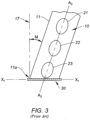
- Fig. 3 illustrates label carrier strip 10 of Fig. 1 when, for various reasons, strip 10 becomes misaligned as shown by angle “M” and moves along longitudinal axis A2-A2 which is not perpendicular to axis X1-X1 of pin 30.
- the edge 11 of carrier strip 10 adjacent pin 30 is subjected to increased "point" tension at point 11a and is susceptible to tearing.
- the edge most susceptible to tearing is edge 1 1 , which forms an obtuse angle with axis X1-X1 of pin 30.
- Fig. 4A and 4B illustrate the second problem noted above - that hot melt adhesive labels driven at speeds of 700 to 1 ,000 labels per minute across a prior art release pin 30 tend to remain adhered to carrier strip 10 when ambient working temperatures are relatively high, such as 90°F.
- Fig. 4B which is a side elevation of Fig. 4A
- hot melt adhesive label 24a simply remains attached to strip 10 as strip 10 is drawn across pin (or label stripper) 30, resulting in an unlabeled produce item.
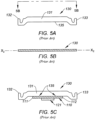
- Figs. 5A-5C illustrate a prior art release (or stripper) plate 130, which is a flat or planar rectangular metal plate having a body 131 and two mounting ears 132 and 133.
- the label carrier strip 1 10 ( Fig.
- Fig. 6A-6C illustrate a first embodiment of the invention, wherein label stripper 230 comprises a generally rectangular metallic body 23 , two mounting ears 232 and 233 and a contoured surface 240 which includes a central stripping segment 245 against which the center of label carrier strip 210 ( Fig. 6C ) runs or engages.
- Contoured surface 240 also includes first and second separation segments 241 , 242 respectively, which are positioned laterally on opposite sides of said central stripping segment and which in the embodiment shown in Fig. 6A are curved and have surfaces inclined in a direction away from the path of the label carrier strip.
- the central stripping segment 245 is also curved.
- the contoured surface 240 in this embodiment is one continuous convex curve, extending across the entire surface 240 and having a convex shape relative to the carrier strip 210 ( Fig. 6C ).
- the contoured surface 240 has a height di of approximately 1 mm for a width of surface 240 of 25mm.
- Label stripper 230 lies in a plane as shown in Fig. 6B .
- the curved shape of separation segments 241 and 242 continuously separates the edges 211 , 212 of the carrier strip from the contoured surface 240, and relieves the tension otherwise formed at the edges 211 and 212 of carrier strip 210, up to a designated, allowable degree of misalignment.
- misalignment is the degree to which the longitudinal axis of the label carrier strip is not perpendicular to the longitudinal axis X2-X2 of release pin 130 ( Fig. 5B ) or label stripper 230( Fig. 6B ) as indicated above by angle "M” in Fig. 3 between axis X1-X1 and a perpendicular line 17 to axis X1-X1.
- Fig. 6B is an elevational view on the line 6B-6B of Fig. 6A .
- Label stripper 230 lies in a plane and has a longitudinal axis X2-X2.
- the smooth, curved separation segments 241 and 242 continuously separate the first and second edges 211 , 212 of carrier strip 210 from the contoured label stripper surface 240, minimizing tension in those edges to reduce tearing of the carrier strip 210, and simultaneously maximizing tension along the center region 215 of carrier strip 210 (along which said labels 210 are positioned) to increase efficiency of label removal.
- the edges 211 , 212 of carrier strip 210 move past the label stripper 230 without touching it or running against it. It is significant to note that the central stripping segment 245 of label stripper surface 240 is the only portion of contoured surface 240 against which the carrier strip 210 runs.
- a second embodiment of the invention is shown in Figs. 7A and 7B and differs from the embodiment shown in Figs. 6A-6C in one respect - a center notch 350 in contoured surface 340.
- Label stripper 330 comprises a generally rectangular metallic body 331 , two mounting ears 332 and 333, and a contoured surface 340 having a central stripping segment 345 across which the label carrier strip (not shown in Figs. 7A and 7B ) runs.
- the curved surface 340 has a smooth, convex shape relative to the carrier strip. Separation segments 341 and 342 on opposite sides of central stripping segment 345 form convex curves relative to the carrier strip.
- the curve forming surface 340 has a height d3 of about 1.0mm for a surface 340 having a length of 25mm.
- the curved, separation segments 341 and 342 reduce and minimize tension in the edges of the carrier strip.
- the curved central portion 345 concentrates tension in the central portion of the carrier strip to increase stripping efficiency of hot melt adhesive labels.
- a center notch 350 is added to distribute the pressure across a designed length d2.
- Notch 350 has two arms 351 and 352, which extend a distance d2 along the length of contoured surface 340.
- Distance d2 is preferably 2-4 mm for a contoured surface 350 having a length of 25 mm.
- the curve forming contoured surface 340 has a height d3 of about 1 mm for a surface 340 having a length of 25 mm.
- the notch 350 will help relieve tearing of the carrier strip due to die cut issues, but will also reduce the label stripper performance. In a field trial, this resulted in the maximum working temperature to be reduced by 20° to maintain release of >97% of the labels, which is typical of the simple curve of edge 235 at 90° F.
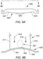
- Figs. 8A and 8B illustrate a further embodiment in which label stripper 530 is the same as label stripper 230 shown in Figs. 6A and 6B above, except for one difference.
- label stripper 230 is planar as shown in Fig. 6B
- label stripper 530 is a curved plate relative to the direction of travel 519 of carrier strip 510 (shown in Fig. 8B only for clarity) and forms a convex surface relative to the direction of travel 519 of carrier strip 510.
- Contoured surface 540 is a continuous curve, having a central stripping segment 545 and separation segments 541 and 542.
- Fig. 8B shows carrier strip 5 0 with first and second edges 5 1 and 512.
- Label 521 is on the longitudinal center of strip 510.
- Figs. 9A-9C illustrate another embodiment in which label stripper 630 has a relatively large central stripping segment 645 of contoured surface 640.
- the label stripper 630 has a body 631 and two mounting ears 632, 633.
- Two separation segments 641 and 642 are inclined segments with straight surfaces.
- the central stripping segment has a flat surface parallel to the carrier strip pathway which extends laterally more than 75% of the width of the carrier strip as shown best in Fig. 9C (Fig. 9C is the same as Fig. 9A with the carrier strip).
- This embodiment applies a relatively uniform tension across the central portion of the carrier strip.
- the edges 611 and 612 of carrier strip are continuously separated from the contoured surface 640 of the label stripper 630 and simply pass through stripper 630 without contacting any part of surface 640.
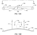
- Figs. 10A and 10B illustrate how the embodiment of Figs. 9A - 9C may be modified by using a curved plate 730 which forms a convex surface relative to the direction of travel of the carrier strip, similar to the curved plate shown in Fig. 8B .
- Label stripper 730 has a metallic body 731 and two mounting ears 732, 733.
- Label stripper 730 has a contoured surface 740 having a central stripping segment 745 and first and second separation segments 741 , 742.
- Fig. 10B shows carrier strip 710 with label 721 in the center of strip 710 moving in a direction 719 across stripper 730.
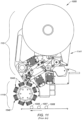
- Figs. 11 and 12 illustrate one prior art labeling machine in which the present invention will operate. They are reproductions of Figs. 2A and 3 from United States patent 9,457,587 , with reference numbers modified.
- Fig. 11 shows an automatic high speed labeling machine 1 ,005 used to apply labels to individual items of produce 1 ,006-1 ,008.
- a detachable label cassette 1110 contains a large number of labels on an elongated carrier strip.
- a label applicator 1 ,1 15 having a plurality of bellows 1045 carried on a rotary head 1 ,040 includes a label stripper 1 ,185 ( Fig. 12 ) to strip individual labels 1 ,142a-1 ,142d ( fig. 12 ) from a label carrier strip 1 ,141 and transfer said labels onto the tip 1 ,041 a of a single bellow 1 ,041 and thereafter onto individual items of produce 1 ,006-1 ,008.
- an improved method of high speed labeling in which a contoured surface such as 240, 340, 540, 640,740 is formed having central stripping segments 245, 345, 545, 645 and 745.
- Each contoured surface has first and second separation segments, as described above.
- Each contoured surface is positioned and shaped to cause the center 215 ( Fig. 6C ) of carrier strip 210 to continuously engage the central stripping segment such as 245 ( Fig. 6C ) to continuously strip labels.
- Both of the separation segments 241 , 242 ( Fig. 6C ) are shaped and positioned to continuously separate the first and second edges 211 , 212 of the carrier strip from the contoured surface 240, allow edge 211 , 212 to move past the label stripper 230 without running against it or touching it.
- the method simultaneously maximizes tension in the center 215 of carrier strip 210 to increase efficiency of label removal, and minimizes tension in the first and second edges 211 , 212 of carrier strip 210 to minimize tearing of the carrier strip.
- the above described method allows the labeling machine to apply between 700 and 1 ,000 labels per minute by a single lane, without tearing the label carrier strip.
- the method also increases efficiency of label removal by more than 20% for hot melt adhesive labels.
- the invention disclosed herein may be used in any produce labeling machine in which release or stripping pins or plates are utilized to separate individual labels from a carrier strip.
- the invention is especially helpful in the labeler shown in United States patent 9,457,587 .
- the label stripper may be adjustably mounted to apply greater or less tension in the carrier strip.
Landscapes
- Labeling Devices (AREA)
- Electronic Switches (AREA)
Claims (14)
- Machine d'étiquetage automatique à grande vitesse utilisée pour appliquer des étiquettes (221) sur des produits (1006 à 1008), dans laquelle un applicateur d'étiquettes (110) présentant une pluralité de soufflets (1045) portés sur une tête rotative (1040) comporte un décolleur d'étiquettes (230) pour décoller des étiquettes individuelles (221) à partir d'une bande de support d'étiquettes (210) et transférer lesdites étiquettes (221) sur la pointe (1041a) d'un seul soufflet (1041) et ensuite sur des produits individuels (1006 à 1008), dans laquelle ladite bande de support d'étiquettes (210) présente une région centrale (215) s'étendant dans une direction longitudinale et des premier et second bords latéraux (11 ;111, 112 ; 211, 212 ; 511), dans laquelle la machine d'étiquetage comprend une surface de décolleur d'étiquettes (240) conçue pour être en contact avec ladite bande de support d'étiquettes (210) afin de séparer des étiquettes individuelles (221) de ladite région centrale (215) de ladite bande de support d'étiquettes (210) lorsqu'elle est attirée à travers ladite surface de décolleur d'étiquettes, caractérisée par :ledit décolleur d'étiquettes (230) présentant un corps (231), deux oreilles de montage (232, 233) et une surface contournée (240), ladite surface contournée (240) comportant un segment de décollement central (245) et des premier et second segments de séparation (241, 242), et étant conçus de telle sorte que ledit segment de décollement central (245) est positionné par rapport à ladite bande de support (210) de telle sorte qu'il soit engagé avec la région centrale (215) de ladite bande de support (210),dans laquelle lesdits premier et second segments de séparation (241, 242) sont positionnés latéralement sur des côtés opposés dudit segment de décollement central (245), et les deux segments de séparation (241, 242) présentent des surfaces inclinées dans une direction à distance de ladite bande de support (210),dans laquelle la machine d'étiquetage est en outre conçue de telle sorte que lors du décollement d'une étiquette par ledit segment de décollement central, lesdits premier et second bords latéraux (211, 212) de ladite bande de support (210) soient espacés de ladite surface contournée (240) par lesdits segments de séparation (241, 242) et n'entrent pas en contact avec ladite surface contournée (240) dudit décolleur d'étiquettes (230).
- Machine d'étiquetage selon la revendication 1, dans laquelle ledit décolleur d'étiquettes (230) est une plaque métallique plane.
- Machine d'étiquetage selon la revendication 2 dans laquelle lesdits premier et second segments de séparation (241, 242) sont incurvés.
- Machine d'étiquetage selon la revendication 3, dans laquelle lesdits premier et second segments de séparation inclinés (241, 242) forment des courbes convexes par rapport à ladite bande de support (210).
- Machine d'étiquetage selon la revendication 4, dans laquelle ladite surface de décolleur d'étiquettes contournée (240) forme une courbe convexe continue à travers toute ladite surface.
- Machine d'étiquetage selon la revendication 5, dans laquelle ladite surface de décolleur d'étiquettes (340) forme une surface convexe (340) présentant une encoche (350) au niveau de son segment de décollement central (345).
- Machine d'étiquetage selon la revendication 1, dans laquelle lesdits premier et second segments de séparation inclinés (241, 242) sont inclinés avec des surfaces droites.
- Machine d'étiquetage selon la revendication 1, dans laquelle ledit décolleur d'étiquettes (530) est une plaque incurvée présentant une surface convexe par rapport à la direction de déplacement (519) de ladite bande de support d'étiquettes (510).
- Procédé destiné à être utilisé dans la machine d'étiquetage automatique à grande vitesse selon une quelconque des revendications 1 à 8, utilisée pour appliquer des étiquettes (221) sur des produits, dans lequel une bande de support d'étiquettes (210) présentant une région centrale (215) et des premier et second bords latéraux (11 ;111, 112 ; 211, 212 ; 511) et portant une pluralité d'étiquettes (221) le long de sa région centrale (215) est attirée à travers le décolleur d'étiquettes (230) afin de séparer des étiquettes individuelles (221) de ladite bande de support,
ledit procédé étant caractérisée par :- le fait d'amener ladite région centrale (215) de ladite bande de support (210) à s'engager de manière continue avec ledit segment de décollement central (245) dudit décolleur d'étiquettes (230) pour décoller des étiquettes (221) ;- le fait d'amener simultanément lesdits premier et second segments de séparation (241, 242) de ladite surface contournée (240) afin de séparer de manière continue les premier et second bords latéraux (11 ;111, 112 ; 211, 212 ; 511) de ladite bande de support (210) par rapport à ladite surface contournée (240), ce qui permet auxdits bords latéraux (11 ; 111, 112 ; 211, 212 ; 511) d'aller au-delà dudit décolleur d'étiquettes sans se déplacer contre celui-ci ;moyennant quoi une tension dans la région centrale (215) de ladite bande de support (210) est rendue maximale pour augmenter le rendement d'enlèvement des étiquettes, et une tension dans lesdits premier et second bords latéraux (11 ;111, 112 ; 211, 212 ; 511) de ladite bande de support (210) est rendue minimale pour réduire le déchirement de ladite bande de support (210). - Procédé selon la revendication 9, dans lequel lesdits premier et second segments de séparation inclinés (241, 242) sont incurvés.
- Procédé selon la revendication 10, dans lequel lesdits premier et second segments de séparation incurvés forment des courbes convexes par rapport à ladite bande de support (210).
- Procédé selon la revendication 11, dans lequel la surface de décolleur d'étiquettes contournée (240) forme une courbe convexe continue à travers toute ladite surface.
- Procédé selon la revendication 12, dans lequel ladite surface de décolleur d'étiquettes (240) forme une surface convexe présentant une encoche (350) au niveau de son segment de décollement central (345).
- Procédé selon la revendication 9, dans lequel ledit décolleur d'étiquettes (530) est une plaque incurvée présentant une surface convexe par rapport à la direction de déplacement (519) de ladite bande de support d'étiquettes (510).
Applications Claiming Priority (2)
| Application Number | Priority Date | Filing Date | Title |
|---|---|---|---|
| US201662498141P | 2016-12-14 | 2016-12-14 | |
| PCT/US2017/000091 WO2018111314A1 (fr) | 2016-12-14 | 2017-12-06 | Système d'étiquetage automatique à grande vitesse ayant un décolleur d'étiquettes amélioré |
Publications (4)
| Publication Number | Publication Date |
|---|---|
| EP3554953A1 EP3554953A1 (fr) | 2019-10-23 |
| EP3554953A4 EP3554953A4 (fr) | 2020-09-02 |
| EP3554953C0 EP3554953C0 (fr) | 2023-08-02 |
| EP3554953B1 true EP3554953B1 (fr) | 2023-08-02 |
Family
ID=62559617
Family Applications (1)
| Application Number | Title | Priority Date | Filing Date |
|---|---|---|---|
| EP17881433.1A Active EP3554953B1 (fr) | 2016-12-14 | 2017-12-06 | Machine et procédé d'étiquetage automatique à grande vitesse ayant un décolleur d'étiquettes amélioré |
Country Status (12)
| Country | Link |
|---|---|
| US (1) | US10427820B2 (fr) |
| EP (1) | EP3554953B1 (fr) |
| AR (2) | AR108121A1 (fr) |
| AU (1) | AU2017377851B2 (fr) |
| CA (1) | CA3040659C (fr) |
| CL (1) | CL2019001585A1 (fr) |
| ES (1) | ES2953521T3 (fr) |
| IL (1) | IL265861B (fr) |
| MX (1) | MX2019006985A (fr) |
| PL (1) | PL3554953T3 (fr) |
| WO (1) | WO2018111314A1 (fr) |
| ZA (1) | ZA201902434B (fr) |
Family Cites Families (30)
| Publication number | Priority date | Publication date | Assignee | Title |
|---|---|---|---|---|
| US3485414A (en) * | 1968-05-13 | 1969-12-23 | Herbert Dinter | Label dispenser with constant tension means |
| US4210484A (en) * | 1978-08-03 | 1980-07-01 | Label-Aire Inc. | Label spreader applicator |
| US4896793A (en) * | 1987-12-04 | 1990-01-30 | Sinclair International Limited | Labelling machines |
| US5162069A (en) * | 1990-07-16 | 1992-11-10 | Accraply Incorporated | Cassette applicator head system |
| DE4406976C1 (de) * | 1994-03-03 | 1995-06-22 | Lohmann Therapie Syst Lts | Verfahren zur Übertragung von einseitig selbstklebenden Abschnitten von einer bewegbaren ersten Bahn auf eine bewegbare zweite Bahn sowie Verwendung des Verfahrens |
| US5660676A (en) * | 1995-10-19 | 1997-08-26 | Brooks; Robert E. | High speed labeler |
| US6230780B1 (en) * | 1998-04-30 | 2001-05-15 | Automated Systems Technology, L.L.C. | Label applicator mechanism and hand-held labeller |
| US20020104623A1 (en) * | 2001-02-05 | 2002-08-08 | Merrill Dale C. | Roller peel plate assembly for labeling machine |
| US6729375B2 (en) * | 2001-06-19 | 2004-05-04 | Joe & Samia Management Inc. | Labelling apparatus and method |
| US6969134B2 (en) * | 2001-10-01 | 2005-11-29 | Zih Corp. | Printer or other media processor with on-demand selective media converter |
| US6896022B2 (en) * | 2003-05-12 | 2005-05-24 | Datacard Corporation | Method and apparatus for attaching card labels |
| WO2005042351A1 (fr) * | 2003-10-31 | 2005-05-12 | Avery Dennison Corporation | Imprimante pour etiquettes distribuant les etiquettes selon un mode sans decollement ou selon un mode a decollement automatique |
| US8006734B2 (en) * | 2003-12-09 | 2011-08-30 | Glue Dots International Llc | System and method for advancing thermoplastic adhesive segment dispensing tape and applying adhesive segments thereby |
| JP2007076721A (ja) * | 2005-09-16 | 2007-03-29 | Seiko Epson Corp | ラベル剥離機構およびプリンタ |
| US8066044B2 (en) * | 2008-04-17 | 2011-11-29 | Hurst International, Llc | Method and apparatus for high speed produce labeling |
| MX2012000976A (es) * | 2009-07-23 | 2012-03-06 | Procter & Gamble | Aplicador de etiquetas por presion. |
| JP5684817B2 (ja) * | 2009-10-13 | 2015-03-18 | ブレイディー・ワールドワイド・インコーポレーテッドBrady Worldwide,Inc. | ラベル貼り装置 |
| US8167017B2 (en) * | 2009-11-13 | 2012-05-01 | Pitney Bowes Inc. | Multi-mode system for dispensing adhesive-backed labels |
| US8047250B2 (en) * | 2009-11-23 | 2011-11-01 | Pitney Bowes Inc. | Postage label dispensing system and repositionable peeler guide therefor |
| US9287724B2 (en) * | 2010-04-12 | 2016-03-15 | Zih Corp. | Printer mobility and scalability |
| JP5801811B2 (ja) * | 2010-08-10 | 2015-10-28 | リンテック株式会社 | シート剥離装置および剥離方法ならびにシート貼付装置および貼付方法 |
| JP5357928B2 (ja) * | 2011-06-16 | 2013-12-04 | 東芝テック株式会社 | ラベルプリンタ |
| US8882955B2 (en) * | 2011-07-07 | 2014-11-11 | Superior Tape & Label Incorporated | Automated labeling method and label supply therefor |
| US8524027B2 (en) * | 2011-07-27 | 2013-09-03 | Brady Worldwide, Inc. | Label dispensing device and method |
| WO2013174973A1 (fr) * | 2012-05-25 | 2013-11-28 | I-Label Bvba | Distributeur d'étiquettes |
| JP6303598B2 (ja) * | 2014-02-28 | 2018-04-04 | ブラザー工業株式会社 | 印刷装置 |
| WO2016032559A1 (fr) * | 2014-08-29 | 2016-03-03 | Sinclair Systems International, Llc | Système d'étiquetage automatique à grande vitesse |
| PL3204304T3 (pl) * | 2014-10-06 | 2020-05-18 | Sinclair Systems International, Llc | Automatycznie drukująca termicznie na żądanie etykieciarka produktów |
| JP6256398B2 (ja) * | 2015-03-24 | 2018-01-10 | ブラザー工業株式会社 | 印刷装置 |
| JP6496223B2 (ja) * | 2015-09-24 | 2019-04-03 | 株式会社ミヤコシ | 積層ラベル体の製造装置 |
-
2017
- 2017-04-11 AR ARP170100927A patent/AR108121A1/es active IP Right Grant
- 2017-12-06 WO PCT/US2017/000091 patent/WO2018111314A1/fr not_active Ceased
- 2017-12-06 AU AU2017377851A patent/AU2017377851B2/en not_active Ceased
- 2017-12-06 EP EP17881433.1A patent/EP3554953B1/fr active Active
- 2017-12-06 PL PL17881433.1T patent/PL3554953T3/pl unknown
- 2017-12-06 US US15/732,638 patent/US10427820B2/en active Active
- 2017-12-06 MX MX2019006985A patent/MX2019006985A/es unknown
- 2017-12-06 ES ES17881433T patent/ES2953521T3/es active Active
- 2017-12-06 CA CA3040659A patent/CA3040659C/fr active Active
-
2019
- 2019-04-04 IL IL265861A patent/IL265861B/en active IP Right Grant
- 2019-04-16 ZA ZA2019/02434A patent/ZA201902434B/en unknown
- 2019-06-10 CL CL2019001585A patent/CL2019001585A1/es unknown
- 2019-07-31 AR ARP190102160A patent/AR116255A2/es unknown
Also Published As
| Publication number | Publication date |
|---|---|
| AU2017377851B2 (en) | 2023-02-23 |
| ZA201902434B (en) | 2022-07-27 |
| ES2953521T3 (es) | 2023-11-14 |
| AR108121A1 (es) | 2018-07-18 |
| EP3554953A1 (fr) | 2019-10-23 |
| AU2017377851A1 (en) | 2019-05-02 |
| CL2019001585A1 (es) | 2019-10-18 |
| PL3554953T3 (pl) | 2023-11-06 |
| EP3554953C0 (fr) | 2023-08-02 |
| EP3554953A4 (fr) | 2020-09-02 |
| AR116255A2 (es) | 2021-04-21 |
| CA3040659A1 (fr) | 2018-06-21 |
| MX2019006985A (es) | 2019-08-16 |
| US20180186490A1 (en) | 2018-07-05 |
| IL265861B (en) | 2019-09-26 |
| US10427820B2 (en) | 2019-10-01 |
| IL265861A (en) | 2019-05-30 |
| WO2018111314A1 (fr) | 2018-06-21 |
| CA3040659C (fr) | 2019-11-05 |
Similar Documents
| Publication | Publication Date | Title |
|---|---|---|
| US4454180A (en) | Labelling system | |
| US5639332A (en) | Method and apparatus for producing labels | |
| US4150183A (en) | Label matrix stripping | |
| DK173492B1 (da) | Samling af klæbemærkater eller klæbemærkesedler og fremgangsmåde til dannelse af denne | |
| GB1563892A (en) | Labelling apparatus | |
| US4260656A (en) | Pin-feed label stock for drive transport systems and method of forming same | |
| CA2096384A1 (fr) | Impression et pose d'etiquettes sans joint | |
| CN109514842A (zh) | 基板保护膜剥离装置 | |
| US5468081A (en) | Tape cutting apparatus | |
| US4358333A (en) | Apparatus for printing, dispensing and applying pressure-sensitive labels adhering to a carrier tape | |
| CN102791586A (zh) | 用于贴标签的设备 | |
| CA3040659C (fr) | Systeme d'etiquetage automatique a grande vitesse ayant un decolleur d'etiquettes ameliore | |
| WO2013174973A1 (fr) | Distributeur d'étiquettes | |
| US20060060294A1 (en) | Method and apparatus for manual labeling of produce | |
| CN102407959A (zh) | 导光板的保护膜包覆装置 | |
| JP4632611B2 (ja) | 二次的支持シート上に位置した可動性一次的支持シートから接着性積層体部分を分配する方法および装置 | |
| EP1876102B1 (fr) | Dispositif d'étiquettage | |
| US4718373A (en) | Adhesive applicator for a labeling machine | |
| CA1104099A (fr) | Traduction non-disponible | |
| US5725713A (en) | Paper sheets or webs with separable self-adhesive labels | |
| US8524027B2 (en) | Label dispensing device and method | |
| CN105314194B (zh) | 贴标签装置及贴标签方法 | |
| EP1055604A1 (fr) | Dispositif et procédé pour découper des étiquettes d'une bande à étiquette adhérant sur une bande support et appliquer ces étiquettes | |
| US20250326515A1 (en) | Labeling machine and method for applying labels to containers | |
| CA1122169A (fr) | Dispositif d'etiquetage |
Legal Events
| Date | Code | Title | Description |
|---|---|---|---|
| STAA | Information on the status of an ep patent application or granted ep patent |
Free format text: STATUS: THE INTERNATIONAL PUBLICATION HAS BEEN MADE |
|
| PUAI | Public reference made under article 153(3) epc to a published international application that has entered the european phase |
Free format text: ORIGINAL CODE: 0009012 |
|
| STAA | Information on the status of an ep patent application or granted ep patent |
Free format text: STATUS: REQUEST FOR EXAMINATION WAS MADE |
|
| 17P | Request for examination filed |
Effective date: 20190624 |
|
| AK | Designated contracting states |
Kind code of ref document: A1 Designated state(s): AL AT BE BG CH CY CZ DE DK EE ES FI FR GB GR HR HU IE IS IT LI LT LU LV MC MK MT NL NO PL PT RO RS SE SI SK SM TR |
|
| AX | Request for extension of the european patent |
Extension state: BA ME |
|
| RIN1 | Information on inventor provided before grant (corrected) |
Inventor name: GILBERT, TODD Inventor name: VEECK, KRIS Inventor name: HOWARTH, SCOTT, M. Inventor name: GUADAGNINI, KEVIN Inventor name: GRAHAM, JUSTIN |
|
| DAV | Request for validation of the european patent (deleted) | ||
| DAX | Request for extension of the european patent (deleted) | ||
| A4 | Supplementary search report drawn up and despatched |
Effective date: 20200803 |
|
| RIC1 | Information provided on ipc code assigned before grant |
Ipc: B65C 9/42 20060101ALI20200728BHEP Ipc: B65C 9/30 20060101ALI20200728BHEP Ipc: B65H 75/02 20060101ALI20200728BHEP Ipc: B65C 11/00 20060101ALI20200728BHEP Ipc: B65H 29/54 20060101ALI20200728BHEP Ipc: B65C 9/18 20060101AFI20200728BHEP Ipc: B65H 79/00 20060101ALI20200728BHEP |
|
| REG | Reference to a national code |
Ref country code: DE Ref legal event code: R079 Ipc: B65C0009000000 Ref country code: DE Ref legal event code: R079 Ref document number: 602017072303 Country of ref document: DE Free format text: PREVIOUS MAIN CLASS: B65C0009180000 Ipc: B65C0009000000 |
|
| RIC1 | Information provided on ipc code assigned before grant |
Ipc: B65C 9/36 20060101ALN20221028BHEP Ipc: B65C 9/00 20060101AFI20221028BHEP |
|
| GRAP | Despatch of communication of intention to grant a patent |
Free format text: ORIGINAL CODE: EPIDOSNIGR1 |
|
| STAA | Information on the status of an ep patent application or granted ep patent |
Free format text: STATUS: GRANT OF PATENT IS INTENDED |
|
| RIC1 | Information provided on ipc code assigned before grant |
Ipc: B65C 9/36 20060101ALN20221207BHEP Ipc: B65C 9/00 20060101AFI20221207BHEP |
|
| INTG | Intention to grant announced |
Effective date: 20230105 |
|
| GRAS | Grant fee paid |
Free format text: ORIGINAL CODE: EPIDOSNIGR3 |
|
| GRAJ | Information related to disapproval of communication of intention to grant by the applicant or resumption of examination proceedings by the epo deleted |
Free format text: ORIGINAL CODE: EPIDOSDIGR1 |
|
| GRAL | Information related to payment of fee for publishing/printing deleted |
Free format text: ORIGINAL CODE: EPIDOSDIGR3 |
|
| STAA | Information on the status of an ep patent application or granted ep patent |
Free format text: STATUS: REQUEST FOR EXAMINATION WAS MADE |
|
| GRAP | Despatch of communication of intention to grant a patent |
Free format text: ORIGINAL CODE: EPIDOSNIGR1 |
|
| STAA | Information on the status of an ep patent application or granted ep patent |
Free format text: STATUS: GRANT OF PATENT IS INTENDED |
|
| INTC | Intention to grant announced (deleted) | ||
| RIC1 | Information provided on ipc code assigned before grant |
Ipc: B65C 9/36 20060101ALN20230508BHEP Ipc: B65C 9/00 20060101AFI20230508BHEP |
|
| GRAA | (expected) grant |
Free format text: ORIGINAL CODE: 0009210 |
|
| STAA | Information on the status of an ep patent application or granted ep patent |
Free format text: STATUS: THE PATENT HAS BEEN GRANTED |
|
| INTG | Intention to grant announced |
Effective date: 20230606 |
|
| AK | Designated contracting states |
Kind code of ref document: B1 Designated state(s): AL AT BE BG CH CY CZ DE DK EE ES FI FR GB GR HR HU IE IS IT LI LT LU LV MC MK MT NL NO PL PT RO RS SE SI SK SM TR |
|
| REG | Reference to a national code |
Ref country code: GB Ref legal event code: FG4D |
|
| REG | Reference to a national code |
Ref country code: CH Ref legal event code: EP |
|
| REG | Reference to a national code |
Ref country code: DE Ref legal event code: R096 Ref document number: 602017072303 Country of ref document: DE |
|
| REG | Reference to a national code |
Ref country code: IE Ref legal event code: FG4D |
|
| U01 | Request for unitary effect filed |
Effective date: 20230830 |
|
| U07 | Unitary effect registered |
Designated state(s): AT BE BG DE DK EE FI FR IT LT LU LV MT NL PT SE SI Effective date: 20230907 |
|
| REG | Reference to a national code |
Ref country code: ES Ref legal event code: FG2A Ref document number: 2953521 Country of ref document: ES Kind code of ref document: T3 Effective date: 20231114 |
|
| U20 | Renewal fee for the european patent with unitary effect paid |
Year of fee payment: 7 Effective date: 20231129 |
|
| PG25 | Lapsed in a contracting state [announced via postgrant information from national office to epo] |
Ref country code: GR Free format text: LAPSE BECAUSE OF FAILURE TO SUBMIT A TRANSLATION OF THE DESCRIPTION OR TO PAY THE FEE WITHIN THE PRESCRIBED TIME-LIMIT Effective date: 20231103 |
|
| PGFP | Annual fee paid to national office [announced via postgrant information from national office to epo] |
Ref country code: GB Payment date: 20231012 Year of fee payment: 7 |
|
| PG25 | Lapsed in a contracting state [announced via postgrant information from national office to epo] |
Ref country code: IS Free format text: LAPSE BECAUSE OF FAILURE TO SUBMIT A TRANSLATION OF THE DESCRIPTION OR TO PAY THE FEE WITHIN THE PRESCRIBED TIME-LIMIT Effective date: 20231202 |
|
| PG25 | Lapsed in a contracting state [announced via postgrant information from national office to epo] |
Ref country code: RS Free format text: LAPSE BECAUSE OF FAILURE TO SUBMIT A TRANSLATION OF THE DESCRIPTION OR TO PAY THE FEE WITHIN THE PRESCRIBED TIME-LIMIT Effective date: 20230802 Ref country code: NO Free format text: LAPSE BECAUSE OF FAILURE TO SUBMIT A TRANSLATION OF THE DESCRIPTION OR TO PAY THE FEE WITHIN THE PRESCRIBED TIME-LIMIT Effective date: 20231102 Ref country code: IS Free format text: LAPSE BECAUSE OF FAILURE TO SUBMIT A TRANSLATION OF THE DESCRIPTION OR TO PAY THE FEE WITHIN THE PRESCRIBED TIME-LIMIT Effective date: 20231202 Ref country code: HR Free format text: LAPSE BECAUSE OF FAILURE TO SUBMIT A TRANSLATION OF THE DESCRIPTION OR TO PAY THE FEE WITHIN THE PRESCRIBED TIME-LIMIT Effective date: 20230802 Ref country code: GR Free format text: LAPSE BECAUSE OF FAILURE TO SUBMIT A TRANSLATION OF THE DESCRIPTION OR TO PAY THE FEE WITHIN THE PRESCRIBED TIME-LIMIT Effective date: 20231103 |
|
| PGFP | Annual fee paid to national office [announced via postgrant information from national office to epo] |
Ref country code: PL Payment date: 20230928 Year of fee payment: 7 |
|
| PGFP | Annual fee paid to national office [announced via postgrant information from national office to epo] |
Ref country code: ES Payment date: 20240118 Year of fee payment: 7 |
|
| PG25 | Lapsed in a contracting state [announced via postgrant information from national office to epo] |
Ref country code: SM Free format text: LAPSE BECAUSE OF FAILURE TO SUBMIT A TRANSLATION OF THE DESCRIPTION OR TO PAY THE FEE WITHIN THE PRESCRIBED TIME-LIMIT Effective date: 20230802 Ref country code: RO Free format text: LAPSE BECAUSE OF FAILURE TO SUBMIT A TRANSLATION OF THE DESCRIPTION OR TO PAY THE FEE WITHIN THE PRESCRIBED TIME-LIMIT Effective date: 20230802 Ref country code: CZ Free format text: LAPSE BECAUSE OF FAILURE TO SUBMIT A TRANSLATION OF THE DESCRIPTION OR TO PAY THE FEE WITHIN THE PRESCRIBED TIME-LIMIT Effective date: 20230802 Ref country code: SK Free format text: LAPSE BECAUSE OF FAILURE TO SUBMIT A TRANSLATION OF THE DESCRIPTION OR TO PAY THE FEE WITHIN THE PRESCRIBED TIME-LIMIT Effective date: 20230802 |
|
| REG | Reference to a national code |
Ref country code: DE Ref legal event code: R097 Ref document number: 602017072303 Country of ref document: DE |
|
| PLBE | No opposition filed within time limit |
Free format text: ORIGINAL CODE: 0009261 |
|
| STAA | Information on the status of an ep patent application or granted ep patent |
Free format text: STATUS: NO OPPOSITION FILED WITHIN TIME LIMIT |
|
| 26N | No opposition filed |
Effective date: 20240503 |
|
| REG | Reference to a national code |
Ref country code: CH Ref legal event code: PL |
|
| PG25 | Lapsed in a contracting state [announced via postgrant information from national office to epo] |
Ref country code: MC Free format text: LAPSE BECAUSE OF FAILURE TO SUBMIT A TRANSLATION OF THE DESCRIPTION OR TO PAY THE FEE WITHIN THE PRESCRIBED TIME-LIMIT Effective date: 20230802 |
|
| PG25 | Lapsed in a contracting state [announced via postgrant information from national office to epo] |
Ref country code: MC Free format text: LAPSE BECAUSE OF FAILURE TO SUBMIT A TRANSLATION OF THE DESCRIPTION OR TO PAY THE FEE WITHIN THE PRESCRIBED TIME-LIMIT Effective date: 20230802 |
|
| REG | Reference to a national code |
Ref country code: IE Ref legal event code: MM4A |
|
| PG25 | Lapsed in a contracting state [announced via postgrant information from national office to epo] |
Ref country code: IE Free format text: LAPSE BECAUSE OF NON-PAYMENT OF DUE FEES Effective date: 20231206 |
|
| PG25 | Lapsed in a contracting state [announced via postgrant information from national office to epo] |
Ref country code: CH Free format text: LAPSE BECAUSE OF NON-PAYMENT OF DUE FEES Effective date: 20231231 |
|
| PG25 | Lapsed in a contracting state [announced via postgrant information from national office to epo] |
Ref country code: IE Free format text: LAPSE BECAUSE OF NON-PAYMENT OF DUE FEES Effective date: 20231206 Ref country code: CH Free format text: LAPSE BECAUSE OF NON-PAYMENT OF DUE FEES Effective date: 20231231 |
|
| PG25 | Lapsed in a contracting state [announced via postgrant information from national office to epo] |
Ref country code: CY Free format text: LAPSE BECAUSE OF FAILURE TO SUBMIT A TRANSLATION OF THE DESCRIPTION OR TO PAY THE FEE WITHIN THE PRESCRIBED TIME-LIMIT; INVALID AB INITIO Effective date: 20171206 |
|
| PG25 | Lapsed in a contracting state [announced via postgrant information from national office to epo] |
Ref country code: HU Free format text: LAPSE BECAUSE OF FAILURE TO SUBMIT A TRANSLATION OF THE DESCRIPTION OR TO PAY THE FEE WITHIN THE PRESCRIBED TIME-LIMIT; INVALID AB INITIO Effective date: 20171206 |
|
| GBPC | Gb: european patent ceased through non-payment of renewal fee |
Effective date: 20241206 |
|
| U90 | Renewal fees not paid: noting of loss of rights |
Free format text: RENEWAL FEE NOT PAID FOR YEAR 08 Effective date: 20250715 |
|
| PG25 | Lapsed in a contracting state [announced via postgrant information from national office to epo] |
Ref country code: GB Free format text: LAPSE BECAUSE OF NON-PAYMENT OF DUE FEES Effective date: 20241206 |
|
| U93 | Unitary patent lapsed |
Free format text: RENEWAL FEE NOT PAID Effective date: 20241231 |
|
| PG25 | Lapsed in a contracting state [announced via postgrant information from national office to epo] |
Ref country code: TR Free format text: LAPSE BECAUSE OF FAILURE TO SUBMIT A TRANSLATION OF THE DESCRIPTION OR TO PAY THE FEE WITHIN THE PRESCRIBED TIME-LIMIT Effective date: 20230802 |
|
| REG | Reference to a national code |
Ref country code: ES Ref legal event code: FD2A Effective date: 20260128 |
|
| PG25 | Lapsed in a contracting state [announced via postgrant information from national office to epo] |
Ref country code: ES Free format text: LAPSE BECAUSE OF NON-PAYMENT OF DUE FEES Effective date: 20241207 |
|
| PG25 | Lapsed in a contracting state [announced via postgrant information from national office to epo] |
Ref country code: PL Free format text: LAPSE BECAUSE OF NON-PAYMENT OF DUE FEES Effective date: 20241206 |