EP3554876B1 - Nabenrad für tandemachsen - Google Patents
Nabenrad für tandemachsen Download PDFInfo
- Publication number
- EP3554876B1 EP3554876B1 EP17822543.9A EP17822543A EP3554876B1 EP 3554876 B1 EP3554876 B1 EP 3554876B1 EP 17822543 A EP17822543 A EP 17822543A EP 3554876 B1 EP3554876 B1 EP 3554876B1
- Authority
- EP
- European Patent Office
- Prior art keywords
- wheel hub
- toothing
- connection sleeve
- wheel
- conical
- Prior art date
- Legal status (The legal status is an assumption and is not a legal conclusion. Google has not performed a legal analysis and makes no representation as to the accuracy of the status listed.)
- Active
Links
Images


Classifications
-
- B—PERFORMING OPERATIONS; TRANSPORTING
- B60—VEHICLES IN GENERAL
- B60K—ARRANGEMENT OR MOUNTING OF PROPULSION UNITS OR OF TRANSMISSIONS IN VEHICLES; ARRANGEMENT OR MOUNTING OF PLURAL DIVERSE PRIME-MOVERS IN VEHICLES; AUXILIARY DRIVES FOR VEHICLES; INSTRUMENTATION OR DASHBOARDS FOR VEHICLES; ARRANGEMENTS IN CONNECTION WITH COOLING, AIR INTAKE, GAS EXHAUST OR FUEL SUPPLY OF PROPULSION UNITS IN VEHICLES
- B60K17/00—Arrangement or mounting of transmissions in vehicles
- B60K17/04—Arrangement or mounting of transmissions in vehicles characterised by arrangement, location or kind of gearing
- B60K17/043—Transmission unit disposed in on near the vehicle wheel, or between the differential gear unit and the wheel
- B60K17/046—Transmission unit disposed in on near the vehicle wheel, or between the differential gear unit and the wheel with planetary gearing having orbital motion
-
- B—PERFORMING OPERATIONS; TRANSPORTING
- B60—VEHICLES IN GENERAL
- B60K—ARRANGEMENT OR MOUNTING OF PROPULSION UNITS OR OF TRANSMISSIONS IN VEHICLES; ARRANGEMENT OR MOUNTING OF PLURAL DIVERSE PRIME-MOVERS IN VEHICLES; AUXILIARY DRIVES FOR VEHICLES; INSTRUMENTATION OR DASHBOARDS FOR VEHICLES; ARRANGEMENTS IN CONNECTION WITH COOLING, AIR INTAKE, GAS EXHAUST OR FUEL SUPPLY OF PROPULSION UNITS IN VEHICLES
- B60K17/00—Arrangement or mounting of transmissions in vehicles
- B60K17/04—Arrangement or mounting of transmissions in vehicles characterised by arrangement, location or kind of gearing
- B60K17/16—Arrangement or mounting of transmissions in vehicles characterised by arrangement, location or kind of gearing of differential gearing
-
- B—PERFORMING OPERATIONS; TRANSPORTING
- B60—VEHICLES IN GENERAL
- B60Y—INDEXING SCHEME RELATING TO ASPECTS CROSS-CUTTING VEHICLE TECHNOLOGY
- B60Y2200/00—Type of vehicle
- B60Y2200/10—Road Vehicles
- B60Y2200/14—Trucks; Load vehicles, Busses
- B60Y2200/142—Heavy duty trucks
-
- F—MECHANICAL ENGINEERING; LIGHTING; HEATING; WEAPONS; BLASTING
- F16—ENGINEERING ELEMENTS AND UNITS; GENERAL MEASURES FOR PRODUCING AND MAINTAINING EFFECTIVE FUNCTIONING OF MACHINES OR INSTALLATIONS; THERMAL INSULATION IN GENERAL
- F16H—GEARING
- F16H2200/00—Transmissions for multiple ratios
- F16H2200/003—Transmissions for multiple ratios characterised by the number of forward speeds
- F16H2200/0034—Transmissions for multiple ratios characterised by the number of forward speeds the gear ratios comprising two forward speeds
-
- F—MECHANICAL ENGINEERING; LIGHTING; HEATING; WEAPONS; BLASTING
- F16—ENGINEERING ELEMENTS AND UNITS; GENERAL MEASURES FOR PRODUCING AND MAINTAINING EFFECTIVE FUNCTIONING OF MACHINES OR INSTALLATIONS; THERMAL INSULATION IN GENERAL
- F16H—GEARING
- F16H2200/00—Transmissions for multiple ratios
- F16H2200/20—Transmissions using gears with orbital motion
- F16H2200/2002—Transmissions using gears with orbital motion characterised by the number of sets of orbital gears
- F16H2200/2007—Transmissions using gears with orbital motion characterised by the number of sets of orbital gears with two sets of orbital gears
-
- F—MECHANICAL ENGINEERING; LIGHTING; HEATING; WEAPONS; BLASTING
- F16—ENGINEERING ELEMENTS AND UNITS; GENERAL MEASURES FOR PRODUCING AND MAINTAINING EFFECTIVE FUNCTIONING OF MACHINES OR INSTALLATIONS; THERMAL INSULATION IN GENERAL
- F16H—GEARING
- F16H3/00—Toothed gearings for conveying rotary motion with variable gear ratio or for reversing rotary motion
- F16H3/44—Toothed gearings for conveying rotary motion with variable gear ratio or for reversing rotary motion using gears having orbital motion
- F16H3/46—Gearings having only two central gears, connected by orbital gears
- F16H3/48—Gearings having only two central gears, connected by orbital gears with single orbital gears or pairs of rigidly-connected orbital gears
- F16H3/50—Gearings having only two central gears, connected by orbital gears with single orbital gears or pairs of rigidly-connected orbital gears comprising orbital conical gears
-
- F—MECHANICAL ENGINEERING; LIGHTING; HEATING; WEAPONS; BLASTING
- F16—ENGINEERING ELEMENTS AND UNITS; GENERAL MEASURES FOR PRODUCING AND MAINTAINING EFFECTIVE FUNCTIONING OF MACHINES OR INSTALLATIONS; THERMAL INSULATION IN GENERAL
- F16H—GEARING
- F16H3/00—Toothed gearings for conveying rotary motion with variable gear ratio or for reversing rotary motion
- F16H3/44—Toothed gearings for conveying rotary motion with variable gear ratio or for reversing rotary motion using gears having orbital motion
- F16H3/62—Gearings having three or more central gears
Definitions
- the present invention addresses a wheel hub for tandem axles, such as heavy vehicles for load transportation having tensile type 6x4, 8x4 or 10x4 configurations, or even those so-called tridem consisting of three tag axles.
- the wheel hub comprises a set of characteristics that enables the switch of the reduction rate of the sun wheel, as well as enables the disengagement and individualized freewheeling.
- the prior art comprises a series of models of vehicles having tandem or tridem axles, such as the so-called "truck”, heavy trucks and the two-axle trucks, or even special vehicles, such as construction and mining machinery, which are generally used for loads transportation.
- these models of vehicles may disclose different configurations regarding the layout of its supporting axles and traction.
- these vehicles may disclose tensile 6X4 configurations and, less often, 8x4 or 10x4, in which out of six, eight or ten contact points, four have traction for providing the vehicle movement.
- tridem in which there are three interconnected drawn axles disclosing six contact points. As it is widely known, these drawn contact points are usually formed by respective tires and wheels of the tandem axles.
- the tag axles have at least one reducing system with the main purpose of providing the speed reduction transferred from the Cardan to running axles and, consequently, to the hubs and wheels, increasing the torque. Therefore, it becomes possible to adjust the vehicles so that they can meet different running conditions, but mostly, enable the increase of the wheels' traction, bearing in mind that depending on the conditions and on the type of transportation, it is aimed to obtain the increase of the traction and, thus, the movement speed of the vehicle is committed through these reduction systems.
- said reduction systems are installed in the axle differential, wherein the reduction is given by the reduction relation between the pinion and the ring of the differential. Additional reduction systems may also be predicted in the axle wheel hubs, by using a well known sun-planetary system.
- the wheel hub models having reduction systems known in the prior art have a configuration in which it is not possible to change the reduction relation, i.e., regardless whether the vehicle is loaded or not, the reduction system will remain triggered, which may affect the fuel consumption.
- axle hub enabled selecting the reduction ration, i.e., that it disclosed a variable reduction range, in order to improve the vehicle's performance depending on the type of use such as, for example, totally loaded, half-loaded, or empty.
- WO 2016/110823 describes a reduction system applied to the wheel hub, of the type for use in a truck or a goods transport vehicle, with at least one pair of side members in the front part there being provided a cab and between said side members the powertrain of the truck consisting of the engine, gearbox, universal joint which connects in rotation the output of the gearbox to the differential, said differential redirecting the rotation of the universal joint to the wheels fixed on the related wheel hubs by means of a pair of drive shafts.
- the invention aims to achieve these objectives, amongst others.
- a wheel hub for an assembly of tandem axles that enables obtaining an adjust of the speed reduction of the wheels by selecting the most appropriate reduction ratio according to the transported load and the land through where the vehicle moves.
- the present invention relates to a wheel hub for tandem axles according to claim 1.
- said wheel hub comprises a connection sleeve that is mounted in the end of the semi-draft having concentric mobility in relation to one of the said conical planetary gears through an actuator system mounted in the end of the supporting structure.
- Said connection sleeve is comprised, further, by a body having a surface with double engagement toothing in order to provide the proper engagement with the toothing predicted in said yoke and in said conical planetary gear.
- the actuator system is a hydraulic, pneumatic, electric, electronic, magnetic, or even a combination of these technologies.
- This actuator system is a two stage pneumatic rotational valve, wherein the first stage is formed by a central chamber within which it is predicted a piston for support of said connection sleeve, and the second stage is constituted of a peripheral chamber having a ring piston provided with an opening that interacts with the flange predicted in the structural body of said connection sleeve.
- said two stage actuator system is a pneumatic rotation valve associated with the auto-calibration system of the loads vehicles, such as the so-called “rodoar” and “tire pressure gauge”.
- said actuator system and, more specifically, the connection sleeve comprises a return element, such as a spring, which purpose is to ensure the natural positioning of said sleeve in the regular condition of low speed and high torque.
- the wheel hub comprises a reduction relation that may vary from 1.6:1; 2:1 or 2.7:1.
- connection sleeve of the wheel hub, object of the present invention may comprise, according to another possible embodiment, an opening for air passage, aiming to prevent the vacuum build-up or unnecessary pressure.
- said yoke with its conical sun gears are mounted in a housing constituted of parts that are screwed, placing said yoke outside the opening center.
- the wheel hub is mounted in the semi-shaft-draft through bearings provided with unitized rollers that ensure the proper functioning, and having low risk of causing damages.
- said yoke toothings, of the conical planetary gear and of the connection sleeve may be openings, notches.
- the present invention also relates to a loads transportation vehicle comprising a mechanical structure formed by a chassis, upon which it is mounted an assembly of tandem axles formed by wheel supporting assemblies placed in the end of the running axles for proper fixation of the wheels with tires, wherein said supporting assemblies comprise wheel hubs according to the present invention and as it has been previously disclosed.
- said vehicle for transportation may be a so-called "truck", heavy truck, or two-axle truck endowed with tandem or tridem axles.
- FIG. 1A shows a loads transportation vehicle (V), of a tensile 6X4 type, which chassis (C) supports an assembly of tandem axles (T) formed by at least four wheels supporting assemblies (S), installed in the end of the running axles for proper fixation of the wheels with tires (R).
- Figure 1B shows a view of one of the wheels supporting assemblies (S) of the assembly of tandem axles of the vehicle (V), wherein said wheels supporting assembly (S) comprises the wheel hub 10, object of the present invention.
- the vehicle (V) also comprises an operator cabin having commands for operating the vehicle, engine, gear, cardan axle, etc., and several other components which details have been intentionally omitted and are not disclosed herein since they are already known in the prior art and the intention is providing a more concise and explanatory description of the invention.
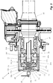
- the wheel hub 10 for tandem axles (T) is formed by a housing 11, within which it is mounted a reduction system 13 formed by planetary gears 13a, 13a' 13a" 13a''' and conical sun gears 13b, 13b' which are accommodated on a supporting structure 14, 14', such as a closing cover formed by two parts.
- Said planetary gears 13a, 13a' 13a" 13a''' may be mounted in rollers and are supported by a yoke 12 that is attached to said supporting structure 14, 14'.
- connection sleeve 17 In the end of said semi-draft 15 a connection sleeve 17 is mounted, and it moves concentrically in relation to said conical sun gear 13b' and to the semi-draft 15, and longitudinally upon the end of the semi-draft 15, according to the actuating state of an actuator system 18 predicted in the end 19 of hub 10.
- Sleeve 17 is mounted in a supportive way to the semi-draft and, thus, it may comprise internal openings (not shown) that cooperate with openings (15a) predicted in the external diameter of the end of the semi-draft 15. Therefore, the connection sleeve 17 rotates at the same rotation speed as the semi-draft 15.
- connection sleeve 17 comprises a surface having one or more toothings (or openings, notches) of double connection, which toothing 17a discloses a configuration corresponding to toothing 12a predicted in said yoke 12, which body was properly worked in such a way to provide the adequate connection to sleeve 17, and the toothing (17b) comprises a configuration corresponding to the toothing 13c of said conical sun gear 13b' which was also properly worked in order to provide a connection to sleeve 17.
- the sleeve also comprises a flange 17c for cooperating with the actuating system, as it will be clearer hereinafter upon explanation of the invention's functioning.
- Said actuator system 18 is a two stage system, wherein the first stage is responsible for providing the displacement of the connection sleeve 17 in order to obtain the disengagement of said conical sun gear 13b', disengaging the toothings 13c e 17b, and then obtaining the proper engagement in yoke 12 through the respective toothings 12a and 17a.
- the second stage is responsible for providing the partial movement of said connection sleeve 17, placing it in an intermediate position between the conical sun gear 13b' and the yoke 12, in order to, thus, free the vehicle's wheel traction.
- the reduction relation of the wheel hub system 10, object of the present invention is activated, and the transmission relation may vary, as being a relation 1.6:1; 2:1 or 2.7:1, depending on the relations between the planetary gears 13a, 13a' 13a" 13a''' and sun gears 13b, 13b' of the reduction system 13.
- connection sleeve 17 comprises an opening (24) for air and hydraulic fluid passage, such as a lubricant that may be present, aiming to avoid the pressure or vacuum and lock the sleeve in a determined position, bearing in mind that the oil that circulates the hub with the reduction system 13 may be the same oil of the differential coming from the differential housing 16.
- a lubricant such as a lubricant that may be present
- the reduction system 13 and, in particular, the yoke 12 with its planetary gears 13a, 13a' 13a" 13a'', are mounted in a housing constituted of two parts 14, 14' that are screwed and place the yoke outside the opening center aiming to avoid any risk of the reduction system to fold.
- connection sleeve 17 that is sliding, preferably it should be mounted attached to the semi-draft 15 having bearings provided with unitized rollers 20, since, in such conditions, the assembly may not disclose any clearances, for it would severely affect the displacement of said connection sleeve 17.
- connection sleeve 17 displaces longitudinally on the end of the semi-draft 15 between the rest position, with the reduction triggered; active, without reduction; and disengaged.
- the two stage actuator system 18 is deactivated and, in such condition, said connection sleeve 17 is in the inactive state and, therefore, its toothing 17b is properly attached to toothing 13c of the conical sun gear 13b'.
- the power of the semi-draft 15 is transmitted towards sleeve 17 and to the planetary-sun system, and the rotation will be reduced by the conical planetary gears 13a, 13a' 13a" 13a''' and sun gears 13b, 13b', in a way that it achieves the torque increase in the wheel.
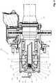
- Fig. 4 shows the wheel hub 10 in the condition in which the actuator system 18 is activated in the condition established as first stage, i.e., totally displaced in the direction of the semi-draft 15.
- the toothing 17b of the connection sleeve 17 is engaged to toothing 13c of the conical sun gear 13b' and, on the other side, toothing 17a of the connection sleeve 17 is engaged to toothing 12a of the yoke 12.
- the power of the semi-draft 15 is directly transferred to the yoke and, consequently, to the hub and to the housing 11, obtaining, therefore, no speed reduction and the torque reduction in the wheel.
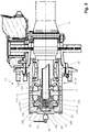
- Fig. 5 shows the wheel hub 10, according to the present invention, in the disparagement condition and free of traction in the vehicle (V) wheel.
- This condition for exemplificative purposes only, is very useful for the cases in which the traction disengagement for turning off the semi-drafts occur, for example, in the 6X2 configuration, wherein the driver deactivates the cardan axle for the second axle and deactivates the wheels' traction to release them from any friction or wear and tear.
- An example of this constructability and applicability may be found in the international patent application PCT/BR2016/0501 82 .
- the wheel hub 10, object of the present invention is in the disengagement condition and, for this purpose, the second stage of the actuator system 18 is activated, in a way that it disposes the said connection sleeve 17 in the intermediate position, in which its toothing 17a is disengaged from toothing 12a of the yoke and, at the same time, the toothing 17b is also disengaged from toothing 13c of the conical sun gear 13c.
- the actuator system 18 of the wheel hub 10 is activated hydraulically, pneumatically, electrically, electronically and/or magnetically, as long as it is able to provide the two stage phased displacement of said connection sleeve 17 and, therefore, provide its connection with the conical sun gear 13b' and the yoke 12.
- the actuator system 18 is a two stage pneumatic rotational valve, wherein the first stage is formed by a central chamber 18a that moves a piston 21 that is contact with the base of said connection sleeve 17, and the second stage is constituted by a peripheral chamber 18b having a ring piston 22 provided with an opening 22a responsible for interacting with a flange 17c predicted in the structural body of said connection sleeve 17.
- connection sleeve 17 has a return mean 23, such as a spring, that provides the movement of sleeve 17 to the position in which its toothing 17b is properly attached to toothing 13c of the conical sun gear 13b'.
- the wheel hub 10, according to the present invention comprises technical and constructive features that turns it into a practical and of easy installation solution for vehicles having assemblies of tandem axles (T). This is because its adaptation slightly affects the structure of these axles, since its installation basically occur in the end of the semi-drafts, dispensing relevant structural modifications in the rest of the components of the assembly of tandem axles (T).
- the present invention also relates to a vehicle (V), such as a loads transportation vehicle, comprising a mechanical structure formed by a chassis (C), within which an assembly of tandem axles (T) is disclosed, such as the tandem or tridem type, constituted by assemblies of wheels supporting (S) installed in the end of the running axles for proper fixation of the wheels with tires (R), wherein said assemblies of wheels supporting (S) of the assembly of tandem axles of vehicle (V) comprise wheel hubs 10, such as defined by the present invention.
- V such as a loads transportation vehicle
- C chassis
- tandem axles such as the tandem or tridem type, constituted by assemblies of wheels supporting (S) installed in the end of the running axles for proper fixation of the wheels with tires (R), wherein said assemblies of wheels supporting (S) of the assembly of tandem axles of vehicle (V) comprise wheel hubs 10, such as defined by the present invention.
Landscapes
- Engineering & Computer Science (AREA)
- Chemical & Material Sciences (AREA)
- Combustion & Propulsion (AREA)
- Transportation (AREA)
- Mechanical Engineering (AREA)
- Retarders (AREA)
Claims (10)
- Radnabe (10) für eine Tandem- oder Tridemachse umfassend ein Gehäuse (11), in dem ein Reduktionssystem (13) aufgenommen und durch kegelförmige Planetenräder (13a, 13a', 13a", 13a''') und Sonnenräder (13b, 13b') gebildet ist, die in einer Trägerstruktur (14, 14') aufgenommen sind, wobei:die Planetenräder (13a, 13a', 13a", 13a''') in einem Gabelstück (12) angebracht sind, das an der Trägerstruktur (14, 14') angebracht ist;die kegelförmigen Sonnenräder (13b, 13b') ausgebildet sind, um auf feste Art und Weise an einem Differentialgehäuse (16) bzw. frei drehbar an einem Ende einer Halbwelle (15) befestigt zu werden;eine Verbindungsmuffe (17) dazu ausgebildet ist, am Ende der Halbwelle (15) angebracht zu sein mit konzentrischer Beweglichkeit bezüglich des kegelförmigen Sonnenrads (13b') mittels eines Antriebssystems (18), das an einem Ende (19) der Trägerstruktur (14, 14') angeordnet ist, wobei die Verbindungsmuffe (17) durch einen Körper gebildet ist, der eine Oberfläche mit doppelter Verbindungsverzahnung aufweist, die eine Konfiguration aufweist, bei der eine erste Verzahnung (17a) der doppelten Verbindungsverzahnung mit der Verzahnung (12a) korrespondiert, die im Gabelstück (12) vorgesehen ist, und eine Konfiguration aufweist, bei der eine zweite Verzahnung (17b) der doppelten Verbindungsverzahnung mit der Verzahnung (13c) korrespondiert, die im kegelförmigen Sonnenrad (13b') vorgesehen ist,dadurch gekennzeichnet, dass das Antriebssystem (18) ein zweistufiges pneumatisches Drehventil ist, wobei die erste Stufe durch eine zentrale Kammer (18a) gebildet ist, in der ein Kolben (21) vorgesehen ist, den die Verbindungsmuffe (17) erfasst, und die zweite Stufe durch eine Umfangskammer (18b) gebildet ist, die einen Ringkolben (22) aufweist, der eine Öffnung (22a) aufweist, die mit einem Flansch (17c) zusammenwirkt, der an dem strukturellen Körper der Verbindungsmuffe (17) vorgesehen ist.
- Radnabe (10) nach Anspruch 1, dadurch gekennzeichnet, dass das zweistufige Antriebssystem (18) ein pneumatisches Drehventil ist, das mit dem Autokalibriersystem des Lastfahrzeugs (V) verbunden ist.
- Radnabe (10) nach Anspruch 1, dadurch gekennzeichnet, dass die Verbindungsmuffe (17) ein Rückstellelement (23), wie z.B. eine Feder, umfasst.
- Radnabe (10) nach Anspruch 1, dadurch gekennzeichnet, dass sie ein Reduktionsverhältnis von 1,6 : 1 ; 2 : 1 oder 2,7 : 1 umfasst.
- Radnabe (10) nach Anspruch 1, dadurch gekennzeichnet, dass die Verbindungsmuffe (17) eine Öffnung für den Luftdurchlass (17) umfasst.
- Radnabe (10) nach Anspruch 1, dadurch gekennzeichnet, dass das Gabelstück (12) mit seinen kegelförmigen Planetenrädern (13a, 13a', 13a", 13a''') in einem Gehäuse angebracht ist, das aus Teilen der Trägerstruktur (14, 14') gebildet ist, die verschraubt sind.
- Radnabe (10) nach Anspruch 1, dadurch gekennzeichnet, dass sie mittels Lagern, die mit vereinheitlichten Walzen (20) versehen sind, an der Halbwelle (15) befestigt angebracht ist.
- Radnabe (10) nach Anspruch 1, dadurch gekennzeichnet, dass die Verzahnungen (12a, 13c, 17a, 17b) Öffnungen oder Nuten sind.
- Fahrzeug mit einem mechanischen Aufbau, der durch ein Fahrgestell (C) gebildet ist, in dem eine Anordnung einer Tandem- oder Tridemachse (T) vorgesehen ist, die aus einer Rad tragenden Anordnung (S) gebildet ist, die am Ende der Laufachsen zur angemessenen Befestigung der Räder mit Reifen (R) angebracht ist, dadurch gekennzeichnet, dass die Rad tragende Anordnung (S) Radnaben (10) nach einem der vorangehenden Ansprüche umfasst.
- Fahrzeug nach Anspruch 9, dadurch gekennzeichnet, dass das Fahrzeug ein Lastwagen oder ein Schwerlastwagen mit einer Tandem- oder Tridemachse ist.
Applications Claiming Priority (2)
| Application Number | Priority Date | Filing Date | Title |
|---|---|---|---|
| BR102016029398-7A BR102016029398B1 (pt) | 2016-12-14 | 2016-12-14 | cubo de roda para eixos combinados tracionados e veículo |
| PCT/BR2017/050379 WO2018107258A1 (en) | 2016-12-14 | 2017-12-12 | Hub wheel for tandem axles |
Publications (2)
| Publication Number | Publication Date |
|---|---|
| EP3554876A1 EP3554876A1 (de) | 2019-10-23 |
| EP3554876B1 true EP3554876B1 (de) | 2021-04-28 |
Family
ID=60888061
Family Applications (1)
| Application Number | Title | Priority Date | Filing Date |
|---|---|---|---|
| EP17822543.9A Active EP3554876B1 (de) | 2016-12-14 | 2017-12-12 | Nabenrad für tandemachsen |
Country Status (6)
| Country | Link |
|---|---|
| US (1) | US11130401B2 (de) |
| EP (1) | EP3554876B1 (de) |
| CN (1) | CN109963734B (de) |
| BR (1) | BR102016029398B1 (de) |
| ES (1) | ES2877145T3 (de) |
| WO (1) | WO2018107258A1 (de) |
Families Citing this family (8)
| Publication number | Priority date | Publication date | Assignee | Title |
|---|---|---|---|---|
| BR102017025512B1 (pt) | 2017-11-28 | 2022-02-22 | On-Highway Brasil Ltda. | Método para monitoramento e controle de operação do eixo traseiro de um veículo |
| EP4046818B1 (de) * | 2019-10-16 | 2025-10-01 | Iveco S.P.A. | Radnabe zum montieren eines rades auf einer achse eines arbeitsfahrzeugs |
| WO2021072518A1 (pt) | 2019-10-16 | 2021-04-22 | CNH Industrial Brasil Ltda. | Cubo de roda para montar uma roda a um eixo de um veículo de trabalho |
| CN110894871A (zh) * | 2019-12-16 | 2020-03-20 | 东风商用车有限公司 | 一种差速结构集成电驱桥减速器换挡机构 |
| IT202000003485A1 (it) * | 2020-02-20 | 2021-08-20 | Iveco Spa | Assale di veicolo comprendente un sistema di riduzione integrato migliorato |
| CN111152837B (zh) * | 2020-03-18 | 2022-08-26 | 盐城富达新能源有限公司 | 一种双轮转向驱动轮 |
| IT202000014653A1 (it) * | 2020-06-18 | 2021-12-18 | Iveco Spa | Mozzo ruota per assale di veicolo comprendente un sistema di riduzione integrato migliorato |
| EP4733112A1 (de) * | 2024-10-25 | 2026-04-29 | Iveco S.P.A. | Radnabe für fahrzeugachse mit verbessertem integriertem reduktionssystem |
Family Cites Families (19)
| Publication number | Priority date | Publication date | Assignee | Title |
|---|---|---|---|---|
| US3184994A (en) | 1962-11-05 | 1965-05-25 | Caterpillar Tractor Co | Wheel drive mechanism |
| DE1430473A1 (de) * | 1963-05-09 | 1968-10-31 | Volvo Penta Ab | Fahrzeugachse mit Kegelrad-Planetengetriebe |
| US5024636A (en) | 1989-06-27 | 1991-06-18 | Fairfield Manufacturing Company, Inc. | Planetary wheel hub |
| US5435790A (en) * | 1991-11-18 | 1995-07-25 | Aeromover Systems Corporation | Plural output differential drive with coaxial shafts |
| WO2002030698A1 (en) | 2000-10-10 | 2002-04-18 | Terex Corporation | Two speed gear box |
| AUPR189900A0 (en) * | 2000-12-05 | 2001-01-04 | Gulf Transport Co Pty Ltd | A drive train assembly for use in powered trailers |
| DE10103726B4 (de) | 2001-01-26 | 2004-01-29 | Kessler & Co Gmbh & Co.Kg | Schaltbares Radnabengetriebe |
| US6672985B2 (en) | 2001-08-30 | 2004-01-06 | Axletech International Ip Holdings, Llc | Independently rotating wheels with planetary drive |
| US7291083B2 (en) * | 2004-08-04 | 2007-11-06 | Arvinmeritor Technology, Llc | Inter-axle differential assembly |
| CN102083648A (zh) * | 2008-07-07 | 2011-06-01 | 迪尔公司 | 电动液压差速器锁 |
| AU2009356696B2 (en) * | 2009-12-18 | 2013-11-07 | Hill's Pet Nutrition, Inc. | Animal feed compositions and processes for producing |
| WO2012007031A1 (en) * | 2010-07-13 | 2012-01-19 | Gkn Driveline International Gmbh | Electric drive for a motor vehicle |
| CA2805163A1 (en) * | 2010-07-20 | 2012-01-26 | Dana Heavy Vehicle Systems Group, Llc | Drive axle system having a clutching device |
| EP2647518B1 (de) | 2012-04-03 | 2015-06-03 | Dana Limited | Aktives Getriebe für Radnabe |
| US9109635B2 (en) | 2013-02-07 | 2015-08-18 | Arvinmeritor Technology, Llc | Axle assembly having a moveable clutch collar |
| CN106489044B (zh) * | 2014-07-03 | 2019-10-18 | 株式会社小松制作所 | 动力传递装置 |
| CN104442374A (zh) * | 2014-11-18 | 2015-03-25 | 绍兴前进齿轮箱有限公司 | 一种农机用转向驱动桥 |
| AU2016205869B2 (en) * | 2015-01-08 | 2019-08-22 | Iveco S.P.A. | Reduction system applied to a wheel hub, and more particularly to a wheel hub connected to a differential of a goods vehicle |
| DE102015118052A1 (de) * | 2015-10-22 | 2016-01-28 | Kessler & Co Gmbh & Co.Kg | Nabenanordnung für Zwillingsräder |
-
2016
- 2016-12-14 BR BR102016029398-7A patent/BR102016029398B1/pt active IP Right Grant
-
2017
- 2017-12-12 WO PCT/BR2017/050379 patent/WO2018107258A1/en not_active Ceased
- 2017-12-12 EP EP17822543.9A patent/EP3554876B1/de active Active
- 2017-12-12 ES ES17822543T patent/ES2877145T3/es active Active
- 2017-12-12 CN CN201780071126.XA patent/CN109963734B/zh active Active
- 2017-12-12 US US16/469,445 patent/US11130401B2/en active Active
Non-Patent Citations (1)
| Title |
|---|
| None * |
Also Published As
| Publication number | Publication date |
|---|---|
| ES2877145T3 (es) | 2021-11-16 |
| EP3554876A1 (de) | 2019-10-23 |
| BR102016029398A2 (pt) | 2018-06-26 |
| BR102016029398B1 (pt) | 2021-03-16 |
| WO2018107258A1 (en) | 2018-06-21 |
| CN109963734B (zh) | 2022-02-01 |
| US11130401B2 (en) | 2021-09-28 |
| CN109963734A (zh) | 2019-07-02 |
| US20200039348A1 (en) | 2020-02-06 |
Similar Documents
| Publication | Publication Date | Title |
|---|---|---|
| EP3554876B1 (de) | Nabenrad für tandemachsen | |
| CN108569085B (zh) | 具有多个离合器套环的车桥组件 | |
| CN109383195B (zh) | 具有副轴的车桥组件 | |
| EP2574490B1 (de) | Antriebsachsenbaugruppe und Ausrücksystem | |
| EP2574489B1 (de) | Antriebsachsenanordnung und Abkopplungssystem | |
| US8469854B1 (en) | Disconnectable driveline for all-wheel drive vehicle | |
| US8562479B2 (en) | Tandem axle having two drivable axles and a drivetrain which can be partially disconnected | |
| US20100234162A1 (en) | Torque distributing drive mechanism for motorized vehicles | |
| EP3333001B1 (de) | Verbindung von wellen für ein fahrzeug | |
| EP3554878B1 (de) | Energieübertragungsanordnung für tandemachsen | |
| US20150207394A1 (en) | Magnet power transmission | |
| CN110171248A (zh) | 具有可移动车轴的驱动车桥总成及操作方法 | |
| EP3554877B1 (de) | Freilaufsystem für tandemachsen | |
| US20230349457A1 (en) | Electronically controlled differential gearing device | |
| JP2008189110A (ja) | 四輪駆動車の動力伝達装置 | |
| US10245946B2 (en) | Platform heavy duty transfer case | |
| CN114728545B (zh) | 用于将车轮安装在作业车辆的轴上的轮毂 | |
| WO2014095630A1 (en) | Coupling mechanism | |
| JPH04121562U (ja) | デフアレンシヤル装置 |
Legal Events
| Date | Code | Title | Description |
|---|---|---|---|
| STAA | Information on the status of an ep patent application or granted ep patent |
Free format text: STATUS: UNKNOWN |
|
| STAA | Information on the status of an ep patent application or granted ep patent |
Free format text: STATUS: THE INTERNATIONAL PUBLICATION HAS BEEN MADE |
|
| PUAI | Public reference made under article 153(3) epc to a published international application that has entered the european phase |
Free format text: ORIGINAL CODE: 0009012 |
|
| STAA | Information on the status of an ep patent application or granted ep patent |
Free format text: STATUS: REQUEST FOR EXAMINATION WAS MADE |
|
| 17P | Request for examination filed |
Effective date: 20190715 |
|
| AK | Designated contracting states |
Kind code of ref document: A1 Designated state(s): AL AT BE BG CH CY CZ DE DK EE ES FI FR GB GR HR HU IE IS IT LI LT LU LV MC MK MT NL NO PL PT RO RS SE SI SK SM TR |
|
| AX | Request for extension of the european patent |
Extension state: BA ME |
|
| DAV | Request for validation of the european patent (deleted) | ||
| DAX | Request for extension of the european patent (deleted) | ||
| GRAP | Despatch of communication of intention to grant a patent |
Free format text: ORIGINAL CODE: EPIDOSNIGR1 |
|
| STAA | Information on the status of an ep patent application or granted ep patent |
Free format text: STATUS: GRANT OF PATENT IS INTENDED |
|
| INTG | Intention to grant announced |
Effective date: 20201210 |
|
| GRAS | Grant fee paid |
Free format text: ORIGINAL CODE: EPIDOSNIGR3 |
|
| GRAA | (expected) grant |
Free format text: ORIGINAL CODE: 0009210 |
|
| STAA | Information on the status of an ep patent application or granted ep patent |
Free format text: STATUS: THE PATENT HAS BEEN GRANTED |
|
| AK | Designated contracting states |
Kind code of ref document: B1 Designated state(s): AL AT BE BG CH CY CZ DE DK EE ES FI FR GB GR HR HU IE IS IT LI LT LU LV MC MK MT NL NO PL PT RO RS SE SI SK SM TR |
|
| REG | Reference to a national code |
Ref country code: GB Ref legal event code: FG4D |
|
| REG | Reference to a national code |
Ref country code: CH Ref legal event code: EP |
|
| REG | Reference to a national code |
Ref country code: AT Ref legal event code: REF Ref document number: 1386693 Country of ref document: AT Kind code of ref document: T Effective date: 20210515 |
|
| REG | Reference to a national code |
Ref country code: DE Ref legal event code: R096 Ref document number: 602017037754 Country of ref document: DE |
|
| REG | Reference to a national code |
Ref country code: IE Ref legal event code: FG4D |
|
| REG | Reference to a national code |
Ref country code: DE Ref legal event code: R082 Ref document number: 602017037754 Country of ref document: DE Representative=s name: KROHER STROBEL RECHTS- UND PATENTANWAELTE PART, DE |
|
| REG | Reference to a national code |
Ref country code: LT Ref legal event code: MG9D |
|
| REG | Reference to a national code |
Ref country code: AT Ref legal event code: MK05 Ref document number: 1386693 Country of ref document: AT Kind code of ref document: T Effective date: 20210428 |
|
| PG25 | Lapsed in a contracting state [announced via postgrant information from national office to epo] |
Ref country code: LT Free format text: LAPSE BECAUSE OF FAILURE TO SUBMIT A TRANSLATION OF THE DESCRIPTION OR TO PAY THE FEE WITHIN THE PRESCRIBED TIME-LIMIT Effective date: 20210428 Ref country code: FI Free format text: LAPSE BECAUSE OF FAILURE TO SUBMIT A TRANSLATION OF THE DESCRIPTION OR TO PAY THE FEE WITHIN THE PRESCRIBED TIME-LIMIT Effective date: 20210428 Ref country code: NL Free format text: LAPSE BECAUSE OF FAILURE TO SUBMIT A TRANSLATION OF THE DESCRIPTION OR TO PAY THE FEE WITHIN THE PRESCRIBED TIME-LIMIT Effective date: 20210428 Ref country code: HR Free format text: LAPSE BECAUSE OF FAILURE TO SUBMIT A TRANSLATION OF THE DESCRIPTION OR TO PAY THE FEE WITHIN THE PRESCRIBED TIME-LIMIT Effective date: 20210428 Ref country code: BG Free format text: LAPSE BECAUSE OF FAILURE TO SUBMIT A TRANSLATION OF THE DESCRIPTION OR TO PAY THE FEE WITHIN THE PRESCRIBED TIME-LIMIT Effective date: 20210728 Ref country code: AT Free format text: LAPSE BECAUSE OF FAILURE TO SUBMIT A TRANSLATION OF THE DESCRIPTION OR TO PAY THE FEE WITHIN THE PRESCRIBED TIME-LIMIT Effective date: 20210428 |
|
| REG | Reference to a national code |
Ref country code: ES Ref legal event code: FG2A Ref document number: 2877145 Country of ref document: ES Kind code of ref document: T3 Effective date: 20211116 |
|
| PG25 | Lapsed in a contracting state [announced via postgrant information from national office to epo] |
Ref country code: GR Free format text: LAPSE BECAUSE OF FAILURE TO SUBMIT A TRANSLATION OF THE DESCRIPTION OR TO PAY THE FEE WITHIN THE PRESCRIBED TIME-LIMIT Effective date: 20210729 Ref country code: IS Free format text: LAPSE BECAUSE OF FAILURE TO SUBMIT A TRANSLATION OF THE DESCRIPTION OR TO PAY THE FEE WITHIN THE PRESCRIBED TIME-LIMIT Effective date: 20210828 Ref country code: PT Free format text: LAPSE BECAUSE OF FAILURE TO SUBMIT A TRANSLATION OF THE DESCRIPTION OR TO PAY THE FEE WITHIN THE PRESCRIBED TIME-LIMIT Effective date: 20210830 Ref country code: PL Free format text: LAPSE BECAUSE OF FAILURE TO SUBMIT A TRANSLATION OF THE DESCRIPTION OR TO PAY THE FEE WITHIN THE PRESCRIBED TIME-LIMIT Effective date: 20210428 Ref country code: NO Free format text: LAPSE BECAUSE OF FAILURE TO SUBMIT A TRANSLATION OF THE DESCRIPTION OR TO PAY THE FEE WITHIN THE PRESCRIBED TIME-LIMIT Effective date: 20210728 Ref country code: LV Free format text: LAPSE BECAUSE OF FAILURE TO SUBMIT A TRANSLATION OF THE DESCRIPTION OR TO PAY THE FEE WITHIN THE PRESCRIBED TIME-LIMIT Effective date: 20210428 Ref country code: RS Free format text: LAPSE BECAUSE OF FAILURE TO SUBMIT A TRANSLATION OF THE DESCRIPTION OR TO PAY THE FEE WITHIN THE PRESCRIBED TIME-LIMIT Effective date: 20210428 Ref country code: SE Free format text: LAPSE BECAUSE OF FAILURE TO SUBMIT A TRANSLATION OF THE DESCRIPTION OR TO PAY THE FEE WITHIN THE PRESCRIBED TIME-LIMIT Effective date: 20210428 |
|
| REG | Reference to a national code |
Ref country code: NL Ref legal event code: MP Effective date: 20210428 |
|
| PG25 | Lapsed in a contracting state [announced via postgrant information from national office to epo] |
Ref country code: SK Free format text: LAPSE BECAUSE OF FAILURE TO SUBMIT A TRANSLATION OF THE DESCRIPTION OR TO PAY THE FEE WITHIN THE PRESCRIBED TIME-LIMIT Effective date: 20210428 Ref country code: SM Free format text: LAPSE BECAUSE OF FAILURE TO SUBMIT A TRANSLATION OF THE DESCRIPTION OR TO PAY THE FEE WITHIN THE PRESCRIBED TIME-LIMIT Effective date: 20210428 Ref country code: RO Free format text: LAPSE BECAUSE OF FAILURE TO SUBMIT A TRANSLATION OF THE DESCRIPTION OR TO PAY THE FEE WITHIN THE PRESCRIBED TIME-LIMIT Effective date: 20210428 Ref country code: CZ Free format text: LAPSE BECAUSE OF FAILURE TO SUBMIT A TRANSLATION OF THE DESCRIPTION OR TO PAY THE FEE WITHIN THE PRESCRIBED TIME-LIMIT Effective date: 20210428 Ref country code: DK Free format text: LAPSE BECAUSE OF FAILURE TO SUBMIT A TRANSLATION OF THE DESCRIPTION OR TO PAY THE FEE WITHIN THE PRESCRIBED TIME-LIMIT Effective date: 20210428 Ref country code: EE Free format text: LAPSE BECAUSE OF FAILURE TO SUBMIT A TRANSLATION OF THE DESCRIPTION OR TO PAY THE FEE WITHIN THE PRESCRIBED TIME-LIMIT Effective date: 20210428 |
|
| REG | Reference to a national code |
Ref country code: DE Ref legal event code: R097 Ref document number: 602017037754 Country of ref document: DE |
|
| PLBE | No opposition filed within time limit |
Free format text: ORIGINAL CODE: 0009261 |
|
| STAA | Information on the status of an ep patent application or granted ep patent |
Free format text: STATUS: NO OPPOSITION FILED WITHIN TIME LIMIT |
|
| 26N | No opposition filed |
Effective date: 20220131 |
|
| PG25 | Lapsed in a contracting state [announced via postgrant information from national office to epo] |
Ref country code: IS Free format text: LAPSE BECAUSE OF FAILURE TO SUBMIT A TRANSLATION OF THE DESCRIPTION OR TO PAY THE FEE WITHIN THE PRESCRIBED TIME-LIMIT Effective date: 20210828 Ref country code: AL Free format text: LAPSE BECAUSE OF FAILURE TO SUBMIT A TRANSLATION OF THE DESCRIPTION OR TO PAY THE FEE WITHIN THE PRESCRIBED TIME-LIMIT Effective date: 20210428 |
|
| PG25 | Lapsed in a contracting state [announced via postgrant information from national office to epo] |
Ref country code: MC Free format text: LAPSE BECAUSE OF FAILURE TO SUBMIT A TRANSLATION OF THE DESCRIPTION OR TO PAY THE FEE WITHIN THE PRESCRIBED TIME-LIMIT Effective date: 20210428 |
|
| REG | Reference to a national code |
Ref country code: CH Ref legal event code: PL |
|
| REG | Reference to a national code |
Ref country code: BE Ref legal event code: MM Effective date: 20211231 |
|
| PG25 | Lapsed in a contracting state [announced via postgrant information from national office to epo] |
Ref country code: LU Free format text: LAPSE BECAUSE OF NON-PAYMENT OF DUE FEES Effective date: 20211212 Ref country code: IE Free format text: LAPSE BECAUSE OF NON-PAYMENT OF DUE FEES Effective date: 20211212 |
|
| PG25 | Lapsed in a contracting state [announced via postgrant information from national office to epo] |
Ref country code: BE Free format text: LAPSE BECAUSE OF NON-PAYMENT OF DUE FEES Effective date: 20211231 |
|
| PG25 | Lapsed in a contracting state [announced via postgrant information from national office to epo] |
Ref country code: LI Free format text: LAPSE BECAUSE OF NON-PAYMENT OF DUE FEES Effective date: 20211231 Ref country code: CH Free format text: LAPSE BECAUSE OF NON-PAYMENT OF DUE FEES Effective date: 20211231 |
|
| P01 | Opt-out of the competence of the unified patent court (upc) registered |
Effective date: 20230523 |
|
| PG25 | Lapsed in a contracting state [announced via postgrant information from national office to epo] |
Ref country code: CY Free format text: LAPSE BECAUSE OF FAILURE TO SUBMIT A TRANSLATION OF THE DESCRIPTION OR TO PAY THE FEE WITHIN THE PRESCRIBED TIME-LIMIT Effective date: 20210428 |
|
| PG25 | Lapsed in a contracting state [announced via postgrant information from national office to epo] |
Ref country code: HU Free format text: LAPSE BECAUSE OF FAILURE TO SUBMIT A TRANSLATION OF THE DESCRIPTION OR TO PAY THE FEE WITHIN THE PRESCRIBED TIME-LIMIT; INVALID AB INITIO Effective date: 20171212 |
|
| PG25 | Lapsed in a contracting state [announced via postgrant information from national office to epo] |
Ref country code: MK Free format text: LAPSE BECAUSE OF FAILURE TO SUBMIT A TRANSLATION OF THE DESCRIPTION OR TO PAY THE FEE WITHIN THE PRESCRIBED TIME-LIMIT Effective date: 20210428 |
|
| PG25 | Lapsed in a contracting state [announced via postgrant information from national office to epo] |
Ref country code: MT Free format text: LAPSE BECAUSE OF FAILURE TO SUBMIT A TRANSLATION OF THE DESCRIPTION OR TO PAY THE FEE WITHIN THE PRESCRIBED TIME-LIMIT Effective date: 20210428 |
|
| PG25 | Lapsed in a contracting state [announced via postgrant information from national office to epo] |
Ref country code: TR Free format text: LAPSE BECAUSE OF FAILURE TO SUBMIT A TRANSLATION OF THE DESCRIPTION OR TO PAY THE FEE WITHIN THE PRESCRIBED TIME-LIMIT Effective date: 20210428 |
|
| PGFP | Annual fee paid to national office [announced via postgrant information from national office to epo] |
Ref country code: GB Payment date: 20251223 Year of fee payment: 9 |
|
| PGFP | Annual fee paid to national office [announced via postgrant information from national office to epo] |
Ref country code: IT Payment date: 20251120 Year of fee payment: 9 |
|
| PGFP | Annual fee paid to national office [announced via postgrant information from national office to epo] |
Ref country code: FR Payment date: 20251223 Year of fee payment: 9 |
|
| PGFP | Annual fee paid to national office [announced via postgrant information from national office to epo] |
Ref country code: ES Payment date: 20260122 Year of fee payment: 9 |
|
| PGFP | Annual fee paid to national office [announced via postgrant information from national office to epo] |
Ref country code: DE Payment date: 20251229 Year of fee payment: 9 |