EP3554423B1 - Vorrichtung zur durchführung oder vorbereitung einer mitralklappenanuloplastik durch einen transfemoralen ansatz - Google Patents
Vorrichtung zur durchführung oder vorbereitung einer mitralklappenanuloplastik durch einen transfemoralen ansatz Download PDFInfo
- Publication number
- EP3554423B1 EP3554423B1 EP17822385.5A EP17822385A EP3554423B1 EP 3554423 B1 EP3554423 B1 EP 3554423B1 EP 17822385 A EP17822385 A EP 17822385A EP 3554423 B1 EP3554423 B1 EP 3554423B1
- Authority
- EP
- European Patent Office
- Prior art keywords
- arms
- mitral
- bearing member
- rod
- counter
- Prior art date
- Legal status (The legal status is an assumption and is not a legal conclusion. Google has not performed a legal analysis and makes no representation as to the accuracy of the status listed.)
- Active
Links
- 210000004115 mitral valve Anatomy 0.000 title claims description 36
- 230000002787 reinforcement Effects 0.000 claims description 29
- 238000000605 extraction Methods 0.000 claims description 19
- 210000005246 left atrium Anatomy 0.000 claims description 7
- 239000004809 Teflon Substances 0.000 claims description 4
- 229920006362 Teflon® Polymers 0.000 claims description 4
- 210000003191 femoral vein Anatomy 0.000 claims description 3
- 239000003550 marker Substances 0.000 claims description 3
- 239000004744 fabric Substances 0.000 claims description 2
- 238000002604 ultrasonography Methods 0.000 claims description 2
- 230000003014 reinforcing effect Effects 0.000 description 26
- 239000004753 textile Substances 0.000 description 14
- 239000007943 implant Substances 0.000 description 6
- 241000287107 Passer Species 0.000 description 3
- 238000004873 anchoring Methods 0.000 description 3
- 230000000694 effects Effects 0.000 description 3
- 238000002360 preparation method Methods 0.000 description 3
- 230000003449 preventive effect Effects 0.000 description 3
- 210000005240 left ventricle Anatomy 0.000 description 2
- 210000000056 organ Anatomy 0.000 description 2
- 210000000115 thoracic cavity Anatomy 0.000 description 2
- 230000003313 weakening effect Effects 0.000 description 2
- NPPQSCRMBWNHMW-UHFFFAOYSA-N Meprobamate Chemical compound NC(=O)OCC(C)(CCC)COC(N)=O NPPQSCRMBWNHMW-UHFFFAOYSA-N 0.000 description 1
- 208000003430 Mitral Valve Prolapse Diseases 0.000 description 1
- 210000003484 anatomy Anatomy 0.000 description 1
- 238000005452 bending Methods 0.000 description 1
- 230000017531 blood circulation Effects 0.000 description 1
- 230000036772 blood pressure Effects 0.000 description 1
- 210000005242 cardiac chamber Anatomy 0.000 description 1
- 230000000747 cardiac effect Effects 0.000 description 1
- 210000000038 chest Anatomy 0.000 description 1
- 230000010339 dilation Effects 0.000 description 1
- 208000014674 injury Diseases 0.000 description 1
- 238000009434 installation Methods 0.000 description 1
- 238000012423 maintenance Methods 0.000 description 1
- 239000000463 material Substances 0.000 description 1
- 238000000034 method Methods 0.000 description 1
- 239000012781 shape memory material Substances 0.000 description 1
- 238000004904 shortening Methods 0.000 description 1
- 238000011477 surgical intervention Methods 0.000 description 1
- 230000008733 trauma Effects 0.000 description 1
- 230000002861 ventricular Effects 0.000 description 1
Images


Classifications
-
- A—HUMAN NECESSITIES
- A61—MEDICAL OR VETERINARY SCIENCE; HYGIENE
- A61F—FILTERS IMPLANTABLE INTO BLOOD VESSELS; PROSTHESES; DEVICES PROVIDING PATENCY TO, OR PREVENTING COLLAPSING OF, TUBULAR STRUCTURES OF THE BODY, e.g. STENTS; ORTHOPAEDIC, NURSING OR CONTRACEPTIVE DEVICES; FOMENTATION; TREATMENT OR PROTECTION OF EYES OR EARS; BANDAGES, DRESSINGS OR ABSORBENT PADS; FIRST-AID KITS
- A61F2/00—Filters implantable into blood vessels; Prostheses, i.e. artificial substitutes or replacements for parts of the body; Appliances for connecting them with the body; Devices providing patency to, or preventing collapsing of, tubular structures of the body, e.g. stents
- A61F2/02—Prostheses implantable into the body
- A61F2/24—Heart valves ; Vascular valves, e.g. venous valves; Heart implants, e.g. passive devices for improving the function of the native valve or the heart muscle; Transmyocardial revascularisation [TMR] devices; Valves implantable in the body
- A61F2/2442—Annuloplasty rings or inserts for correcting the valve shape; Implants for improving the function of a native heart valve
- A61F2/2466—Delivery devices therefor
-
- A—HUMAN NECESSITIES
- A61—MEDICAL OR VETERINARY SCIENCE; HYGIENE
- A61F—FILTERS IMPLANTABLE INTO BLOOD VESSELS; PROSTHESES; DEVICES PROVIDING PATENCY TO, OR PREVENTING COLLAPSING OF, TUBULAR STRUCTURES OF THE BODY, e.g. STENTS; ORTHOPAEDIC, NURSING OR CONTRACEPTIVE DEVICES; FOMENTATION; TREATMENT OR PROTECTION OF EYES OR EARS; BANDAGES, DRESSINGS OR ABSORBENT PADS; FIRST-AID KITS
- A61F2/00—Filters implantable into blood vessels; Prostheses, i.e. artificial substitutes or replacements for parts of the body; Appliances for connecting them with the body; Devices providing patency to, or preventing collapsing of, tubular structures of the body, e.g. stents
- A61F2/02—Prostheses implantable into the body
- A61F2/24—Heart valves ; Vascular valves, e.g. venous valves; Heart implants, e.g. passive devices for improving the function of the native valve or the heart muscle; Transmyocardial revascularisation [TMR] devices; Valves implantable in the body
- A61F2/2442—Annuloplasty rings or inserts for correcting the valve shape; Implants for improving the function of a native heart valve
- A61F2/2445—Annuloplasty rings in direct contact with the valve annulus
-
- A—HUMAN NECESSITIES
- A61—MEDICAL OR VETERINARY SCIENCE; HYGIENE
- A61F—FILTERS IMPLANTABLE INTO BLOOD VESSELS; PROSTHESES; DEVICES PROVIDING PATENCY TO, OR PREVENTING COLLAPSING OF, TUBULAR STRUCTURES OF THE BODY, e.g. STENTS; ORTHOPAEDIC, NURSING OR CONTRACEPTIVE DEVICES; FOMENTATION; TREATMENT OR PROTECTION OF EYES OR EARS; BANDAGES, DRESSINGS OR ABSORBENT PADS; FIRST-AID KITS
- A61F2220/00—Fixations or connections for prostheses classified in groups A61F2/00 - A61F2/26 or A61F2/82 or A61F9/00 or A61F11/00 or subgroups thereof
- A61F2220/0008—Fixation appliances for connecting prostheses to the body
- A61F2220/0016—Fixation appliances for connecting prostheses to the body with sharp anchoring protrusions, e.g. barbs, pins, spikes
-
- A—HUMAN NECESSITIES
- A61—MEDICAL OR VETERINARY SCIENCE; HYGIENE
- A61F—FILTERS IMPLANTABLE INTO BLOOD VESSELS; PROSTHESES; DEVICES PROVIDING PATENCY TO, OR PREVENTING COLLAPSING OF, TUBULAR STRUCTURES OF THE BODY, e.g. STENTS; ORTHOPAEDIC, NURSING OR CONTRACEPTIVE DEVICES; FOMENTATION; TREATMENT OR PROTECTION OF EYES OR EARS; BANDAGES, DRESSINGS OR ABSORBENT PADS; FIRST-AID KITS
- A61F2220/00—Fixations or connections for prostheses classified in groups A61F2/00 - A61F2/26 or A61F2/82 or A61F9/00 or A61F11/00 or subgroups thereof
- A61F2220/0025—Connections or couplings between prosthetic parts, e.g. between modular parts; Connecting elements
- A61F2220/0075—Connections or couplings between prosthetic parts, e.g. between modular parts; Connecting elements sutured, ligatured or stitched, retained or tied with a rope, string, thread, wire or cable
-
- A—HUMAN NECESSITIES
- A61—MEDICAL OR VETERINARY SCIENCE; HYGIENE
- A61F—FILTERS IMPLANTABLE INTO BLOOD VESSELS; PROSTHESES; DEVICES PROVIDING PATENCY TO, OR PREVENTING COLLAPSING OF, TUBULAR STRUCTURES OF THE BODY, e.g. STENTS; ORTHOPAEDIC, NURSING OR CONTRACEPTIVE DEVICES; FOMENTATION; TREATMENT OR PROTECTION OF EYES OR EARS; BANDAGES, DRESSINGS OR ABSORBENT PADS; FIRST-AID KITS
- A61F2230/00—Geometry of prostheses classified in groups A61F2/00 - A61F2/26 or A61F2/82 or A61F9/00 or A61F11/00 or subgroups thereof
- A61F2230/0063—Three-dimensional shapes
- A61F2230/0093—Umbrella-shaped, e.g. mushroom-shaped
-
- A—HUMAN NECESSITIES
- A61—MEDICAL OR VETERINARY SCIENCE; HYGIENE
- A61F—FILTERS IMPLANTABLE INTO BLOOD VESSELS; PROSTHESES; DEVICES PROVIDING PATENCY TO, OR PREVENTING COLLAPSING OF, TUBULAR STRUCTURES OF THE BODY, e.g. STENTS; ORTHOPAEDIC, NURSING OR CONTRACEPTIVE DEVICES; FOMENTATION; TREATMENT OR PROTECTION OF EYES OR EARS; BANDAGES, DRESSINGS OR ABSORBENT PADS; FIRST-AID KITS
- A61F2250/00—Special features of prostheses classified in groups A61F2/00 - A61F2/26 or A61F2/82 or A61F9/00 or A61F11/00 or subgroups thereof
- A61F2250/0058—Additional features; Implant or prostheses properties not otherwise provided for
- A61F2250/0065—Additional features; Implant or prostheses properties not otherwise provided for telescopic
-
- A—HUMAN NECESSITIES
- A61—MEDICAL OR VETERINARY SCIENCE; HYGIENE
- A61F—FILTERS IMPLANTABLE INTO BLOOD VESSELS; PROSTHESES; DEVICES PROVIDING PATENCY TO, OR PREVENTING COLLAPSING OF, TUBULAR STRUCTURES OF THE BODY, e.g. STENTS; ORTHOPAEDIC, NURSING OR CONTRACEPTIVE DEVICES; FOMENTATION; TREATMENT OR PROTECTION OF EYES OR EARS; BANDAGES, DRESSINGS OR ABSORBENT PADS; FIRST-AID KITS
- A61F2250/00—Special features of prostheses classified in groups A61F2/00 - A61F2/26 or A61F2/82 or A61F9/00 or A61F11/00 or subgroups thereof
- A61F2250/0058—Additional features; Implant or prostheses properties not otherwise provided for
- A61F2250/0096—Markers and sensors for detecting a position or changes of a position of an implant, e.g. RF sensors, ultrasound markers
- A61F2250/0098—Markers and sensors for detecting a position or changes of a position of an implant, e.g. RF sensors, ultrasound markers radio-opaque, e.g. radio-opaque markers
Definitions
- the invention relates to a device for performing or preparing a transfemoral annuloplasty of the mitral valve of a heart.
- the purpose of the annuloplasty is to reduce the caliber of the mitral ring by shortening, by bending the attachment of the small valve, the fulcrum being caught between the commissures.
- the term “commissure” is understood to mean narrowing of the perimeter of the posterior part of the mitral annulus by making folds thereon through points, with the result of a reduction in the antero-posterior and latero-lateral diameter of the mitral valve.
- the invention also finds an advantageous application for the placement, on the mitral ring, of a preventive ring, called a preparation or attachment ring, intended to subsequently receive a mitral valve implant.
- a mitral annuloplasty is performed as a means of correcting a mitral leak, the mechanism of which is dilation of the mitral ring (with loss of coaptation of the valve edges) or, in addition to the correction of leakage with another mechanism, (mitral valve prolapse) to increase the coaptation of the posterior mitral valve to the anterior mitral valve
- a mitral annuloplasty is a long and heavy operation that requires the opening of one of the heart chambers, the heart and the rib cage with extracorporeal blood circulation.
- the device comprises a body equipped with a handle and at least one control member capable of acting on an assembly for the establishment and fixing of a braid at the level of the mitral ring by means of elements of suture.
- This device is advantageous in that the assembly has means capable of allowing the extraction of the suture through the mitral ring while being capable of gripping the braid and being anchored on the periphery of the mitral ring under a pinching effect of said suture by exerting two opposing pressure bearing forces.
- fixation of the implant relative to the mitral annulus is improved by exerting an opposing downforce and counter-backing force to effect precise perforation and passage of anchoring material in a relatively short time. short and without weakening the adjacent tissue.
- the device of the state of the art is designed to pass through the thoracic cavity between two ribs in order to enter the left ventricle passing through the apex of the heart, and thus requires a heavy and invasive surgical intervention.
- the document WO2014 / 195786 describes a prior art according to the preamble of claim 1.
- the aim of the invention is to remedy the drawbacks of the state of the art in a safe, simple, efficient and rational manner.
- the problem which the invention proposes to solve is to facilitate the operation of mitral annuloplasty.
- a device for performing or preparing a transfemoral annuloplasty of the mitral valve, and intended to be positioned in a sealed introducer placed in a femoral vein to penetrate into the left atrium of the heart by passing through its septal wall.
- the device according to the invention makes it possible, in combination with a handle and actuating means which are not part of the invention, to perform the mitral annuloplasty operation by the transfemoral route going up through the vena cava.
- the operation is light and minimally invasive.
- the active assembly of the device navigates into the vena cava where blood pressure is relatively low.
- the device also makes it possible to prepare a subsequent annuloplasty operation by allowing the placement of a reinforcing ring in the form of a preventive ring, called preparation or attachment ring, intended to subsequently receive a mitral valve implant. .
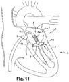
- the device (1) makes it possible to perform a surgical operation, called a mitral annuloplasty, consisting in repairing the mitral annulus (2) of the heart (3) of a patient suffering from a mitral leak.
- the device also makes it possible to prepare a subsequent annuloplasty operation by allowing the placement of a reinforcing ring in the form of a preventive ring, called preparation or attachment ring, intended to subsequently receive a mitral valve implant. .
- the device (1) according to the invention is intended to be positioned in a sealed introducer of any known and appropriate type (not shown) and with a diameter less than or equal to 8 mm, placed in a femoral vein in order to ascend and penetrate into it.
- a sealed introducer of any known and appropriate type (not shown) and with a diameter less than or equal to 8 mm, placed in a femoral vein in order to ascend and penetrate into it.
- the device (1) comprises a handling rod (6), at the end of which is arranged an assembly for the establishment and fixing of a reinforcing ring (7), for example made of textile, at the level of the mitral valve.
- the other end of the rod (6) is intended to cooperate with a handle subject to control means, not shown, for example in the form of a trigger, for actuating the assembly.
- the device (1) according to the invention makes it possible, under radiographic control, after having ascended the vena cava, to make the assembly penetrate into the left atrium (4) of the heart (3) by passing through the septal wall ( 5). Then, when the assembly is in the left atrium (4) of the heart (3), it is able to pass through the mitral valve to come and deploy on the ventricle side below said mitral valve and take support under the mitral ring (2).
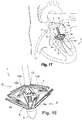
- the assembly comprises a support member (8) comprising a plurality of arms (8a) pivotally connected to an ogive (9) arranged at the end of the rod (6 ).
- the rounded end of the bullet (9) is a-traumatic.
- the arms (8a) are articulated and pivotally mounted to pass, under the action of the control means, from a folded position ( Fig. 2 or Fig. 14 ) along the rod (6) to a deployed position ( Fig. 4 or Fig. 16 ), like an umbrella, separated from the rod (6).
- each arm (8a) of the support member (8) can extend in a curved direction or be flexible in order to be able to adopt a curved position.
- each arm (8a) can be broken by an articulation point allowing the folding of the arm (8a) around said articulation point.
- the end of each arm (8a) can be made up of several branches, able to move away from each other after the passage of the mitral valve strings to form several points of. support under the mitral ring.
- each of the free ends of the arms (8a) of the support member (8) is shaped, for example in the form of a loop, each to receive a piece of textile (10). made of felt or Teflon, known to those skilled in the art under the English term "pledget".
- the pieces of textile (10) are intended to be pressed under the mitral ring (2) and to be fixed by sutures (11) against the support of the reinforcing ring (7), as will be described. lower.
- the arms (8a) of the support member (8) are deployed manually, either all together or selectively and independently of each other to more easily pass the ropes of the device. mitral ring and adapt to the geometry of the mitral ring (2). To better adapt to the geometry of the mitral ring (2), which is not necessarily circular, the arms (8a) are telescopic to have different lengths.
- the arms (8a) can be deployed by mechanical means (not shown) which include the control means. For example, screwing in a thumbwheel can allow the arms (8a) to be deployed.
- the arms (8a) are self-expanding and are inserted into a sleeve (not shown) when they are in the folded position, and are extracted from said sleeve in the deployed position.
- the a-traumatic warhead (9) can act as a sheath.
- the arms (8a) are hingedly connected to a support, such as a socket, slidably mounted on the rod (6) to come to be housed in the ogive (9) in the folded position of the arms ( 8a).
- the assembly comprises a counter-support member (12) comprising a plurality of arms (12a), at the free end of which the reinforcing ring (7) is held. More precisely, each arm (12a) has a free end forming a fork (12b), see figure 9 , the ends of which are shaped as hooks to hold the reinforcing ring (7). With reference to figures 7A and 8A , each arm (12a) internally comprises a slide (12c) extended by a spatula (12d).
- the slide (12c) is secured to means (not shown), such as a cable for example, making it possible to slide the slide (12c) inside the arm (12a) so as to pass the spatula (12d ) a locking position of the reinforcing ring (7) in which it is located under the latter ( Fig. 7A ), to a withdrawn position of release of the reinforcement ring (7) ( Fig. 8A ).
- the spatula (12d) is in the form of two parallel fingers defining between them a passage for a needle as will be described below.
- the arms (12a) of the counter-support member (12) are pivotally connected to a support (13), such as a bushing, disposed coaxially with the rod (6) and mounted with the ability to slide along of it.
- the arms (12a) of the counter-support member (12) are articulated and pivotably mounted so as to pass, under the action of the control means, from a folded position along the rod (6) to a deployed position away from the rod (6) to make the counter-support on the mitral ring (2) and position the reinforcing ring (7) in counter-pressure and in line with the arms (8a) of the organ d 'support (8).
- the arms (12a) of the counter-support member (12) can be deployed simultaneously or selectively and independently of each other. others, be telescopic, and be self-expanding and arranged in a sleeve in their folded position.
- the arms (8a) of the support member (8) and the arms (12a) of the counter-support member (12) open like an umbrella and come in correspondence on either side of the mitral ring (2) to form a support / counter-support.
- This characteristic then makes it possible to pierce the mitral ring (2) in a simple, ideal way and without traction to fix the reinforcement ring (7), as will be described below, by means of means (14) suture extraction (11).
- the two embodiments presented differ in the technique of fixing the reinforcing ring (7).
- each arm (8a) internally comprises a needle (15) mounted with the ability to move in translation to extend beyond the free end of the arms (8a), and release the sutures (11) to fix the reinforcing ring. (7).
- the needles (15) are shaped to allow the engagement, guidance and maintenance of the sutures (11) projecting from the needle (15).
- the needles (15) are intended to be extracted to pierce the mitral ring (2) and protrude from the top face of the mitral ring (2), opening out at the inside the fingers (12d) and forks (12b) of the corresponding arms (12a) of the counter-support member (12). Then, each suture (11) in the form of a thread (11a) made of a shape memory material will automatically, after being released from the needle (15), be deformed to create an anchor loop around of the reinforcement ring (7) and in the thickness of the mitral ring (2) to allow the attachment of said reinforcement ring (7) to the mitral ring (2).
- the needles (15) do not pierce the mitral ring (2) and deliver sutures (11) in the form of staples (11b) which are shaped as a point to pass through them. even the mitral ring (2) and the reinforcement ring (7), and which include anchoring parts (11c), such as arpon ends, to prevent the removal of said clips (11b) and to lock the fixation of the reinforcement ring (7) on the mitral ring (2).
- anchoring parts (11c) such as arpon ends
- the reinforcement ring (7) is fixed from above the mitral ring (2).
- the means (14) for extracting sutures (11) comprise a plurality of arms (14a) pivotally connected to a support (15), such as a sleeve, arranged coaxially with the rod (6) so as to pass, under the action of the control means, from a folded position along the rod (6) to a deployed position separated from the rod (6).
- each arm (14a) of the extraction means (14) When the arms (14a) of the extraction means (14) are in the deployed position, they are in correspondence with the arms (12a) of the counter-support member (12).
- each arm (14a) comprises internally, and in the same manner as for the first embodiment, a needle (15) for delivering a suture in the form of a wire (11a) or a clip (11b) designed to be anchored on the periphery of the mitral valve and to fix the reinforcing ring (7) there.
- the sutures (11) fix the pieces of textile (10) in reinforcement and against the support of the reinforcement ring (7), and on the other side of the mitral ring (2 ).
- the pieces of textile (10) form reinforcements for the sutures (11), so that the tension of the suture (11) is distributed over the entire piece of textile (10), not directly over the ring mitral (2).
- the textile pieces (10) provide protection against trauma due to the tension of the suture (11).
- the arms (14a) of the means (14) d can be deployed simultaneously or selectively and independently of each other, be telescopic, and be self-expanding and arranged in a sheath in their folded position.
- each arm (14a) which the extraction means (14) comprise is connected to the support element (15) by a link (16) to form a stable support during the suturing operation and for fixing the reinforcement ring (7).
- the reinforcing ring (7) constitutes a prosthetic implant capable of reducing the caliber of the mitral ring (2) in order to reduce or even eliminate mitral leaks.
- the reinforcing ring (7) is subject to a means (not shown) capable of making it possible to reduce its circumference after it has been placed and fixed on the periphery of the mitral ring (2), such as indicated.
- these means are constituted by a traction cord mounted freely in translation and to slide freely in the central core of the reinforcing ring (7) to allow, under a traction effect, to ensure the gathering of the 'ring and, consequently, the decrease in its diameter.
- the surgeon removes the device (1), and only the two ends of the wire (11a) which constitutes the axial core of the ring protrude from the introducer.
- the wire under radio control, by exerting a simple fraction on the wire, one causes concomitantly the tightening of the ring of the valve. After finding the right tension for the right diameter, the wire can be crimped with a knot or clip and then cut.
- the characteristics of the device (1) according to the invention provide numerous advantages over existing solutions.
- the fact of passing by the transfemoral route makes it possible to reduce the duration and the invasiveness of the operation.
- With a two-dimensional ultrasound section of the atrioventricular junction it is possible to visualize the desired entrapment of the device (1) on the small mitral valve on the ventricular side.
- the installation is guided by the anatomy of the tissues and the resistance that the operator perceives in the abutment position of the support member (8) and the counter-support member (12)
- the device (1) makes it possible to exert two opposing support and counter-support forces to perform the perforation of the tissues and the passage of the sutures (11) anchoring without risk of weakening said fabric by eliminating any risk of trial and error.
- mitral annulus tissue (2) and adjacent tissues are punctured more efficiently in one go with optimal suture hold (11).
- the arms (8a) of the support member (8) and / or the arms (12a) of the counter-support member (12) and / or the arms (14a) of the means (14 ) extraction each comprise a radiopaque and / or echographic marker allowing the surgeon to carry out a 2D or 3D check of their position as the operation progresses.
Landscapes
- Health & Medical Sciences (AREA)
- Cardiology (AREA)
- Oral & Maxillofacial Surgery (AREA)
- Transplantation (AREA)
- Engineering & Computer Science (AREA)
- Biomedical Technology (AREA)
- Heart & Thoracic Surgery (AREA)
- Vascular Medicine (AREA)
- Life Sciences & Earth Sciences (AREA)
- Animal Behavior & Ethology (AREA)
- General Health & Medical Sciences (AREA)
- Public Health (AREA)
- Veterinary Medicine (AREA)
- Prostheses (AREA)
Claims (10)
- Vorrichtung (1) zur Ausführung oder Vorbereitung einer Annuloplastie auf transfemoralem Weg der Mitralklappe eines Herzens, und dazu bestimmt, in eine dichte Einführungsvorrichtung eingesetzt zu werden, die in einer Femoralvene positioniert ist um in den linken Vorhof des Herzens einzudringen, durch seine Septalwand hindurch, mit einer Baugruppe, die mit einem Griff zusammenarbeiten kann, der über Steuermittel bedient wird, zur Betätigung der Baugruppe zum Einsetzen und zur Befestigung eines Verstärkungsrings (7) auf dem Mitralring, diese Baugruppe ist am Ende einer Manipulatorstange (6) angeordnet und umfasst:- ein Stützelement (8) mit mehreren Armen (8a), die sich unter dem Mitralring gleichmäßig über die Peripherie der Mitralklappe verteilt abstützen können;- ein Widerlager (12), mit mehreren Armen (12a), an deren freien Ende der Verstärkungsring (7) vorgesehen ist, die Arme (12a), sind kippbar mit einem Halter (13) verbunden, der koaxial zur Stange (6) angeordnet ist, so dass sie unter der Wirkung der Steuermittel aus einer entlang der Stange (6) eingeklappten Position in eine zur Stange (6) abgewinkelte Position geklappt werden können, um das Widerlager zum Mitralring zu bilden und den Verstärkungsring (7) zu positionieren, dadurch gekennzeichnet, dass die mehreren Arme (8a) des Stützelementes kippbar mit dem Endstück der Stange (6) verbunden sind, so dass sie unter der Wirkung der Steuermittel aus einer entlang der Stange (6) eingeklappten Position in eine zur Stange (6) abgewinkelte Position geklappt werden können, und dadurch dass die Baugruppe Mittel (14) zur Extraktion von Nahtmaterial (11) enthält, um den Verstärkungsring (7) am Mitralring zu befestigen.
- Vorrichtung (1) nach Anspruch 1, dadurch gekennzeichnet, dass die Arme (8a) des Stützelementes (8) und/ oder die Arme (12a) des Widerlagers (12) kippbar mit dem Halter (13) verbunden sind, der koaxial zur Stange (6) angeordnet ist, so dass sie unter der Wirkung der Steuermittel gleichzeitig oder selektiv und unabhängig voneinander aus der eingeklappten Position in die abgewinkelte Position geklappt werden können.
- Vorrichtung (1) nach Anspruch 1, dadurch gekennzeichnet, dass die Arme (8a) des Stützelementes (8) und/ oder die Arme (12a) des Widerlagers in der eingeklappten Position innerhalb einer Hülse untergebracht werden, aus der sie hinausgestoßen werden können und sich von selbst in die abgewinkelte Position ausklappen.
- Vorrichtung (1) nach Anspruch 1, dadurch gekennzeichnet, dass die Arme (8a) des Stützelementes (8) und/ oder die Arme (12a) des Widerlagers (12) jeweils einen für Strahlen undurchlässigen und/ oder Ultraschall- Marker enthalten.
- Vorrichtung (1) nach Anspruch 1, dadurch gekennzeichnet, dass die Arme (8a) des Stützelementes (8) und/ oder die Arme (12a) des Widerlagers (12) Teleskoparme sind.
- Vorrichtung (1) nach Anspruch 1, dadurch gekennzeichnet, dass die Mittel (14) zur Extraktion des Nahtmaterials (11) mehrere Arme (14a) enthalten, die kippbar mit einem Halter (15) verbunden sind, der koaxial zur Stange (6) angeordnet ist, so dass sie unter der Wirkung des Steuermittels aus einer entlang der Stange (6) eingeklappten Position in eine zur Stange (6) abgewinkelte Position geklappt werden können, entsprechend den Armen (12a) des Widerlagers (12), jeder Arm (14a) enthält in seinem Inneren Nahtmaterial (11), das extrahiert werden kann, um an der Peripherie der Mitralklappe verankert zu werden und dort den Verstärkungsring (7) zu befestigen.
- Vorrichtung (1) nach Anspruch 1, dadurch gekennzeichnet, dass jeder Arm (8a) des Stützelementes (8) gekrümmt, abgewinkelt, mit Gelenken versehen oder flexibel ist, um das Hindurchführen durch die Sehnenfäden der Mitralklappe zu erleichtern.
- Vorrichtung (1) nach Anspruch 1, dadurch gekennzeichnet, dass das Endstück jedes Arms (8a) aus mehreren Ästen bestehen kann, die sich voneinander abspreizen können, nachdem sie durch die Sehnenfäden der Mitralklappe hindurchgeführt wurden, um mehrere Abstützpunkte auf dem Mitralring zu bilden.
- Vorrichtung (1) nach Anspruch 1, dadurch gekennzeichnet, dass jeder Arm (8a) des Stützelementes (8) in seinem Inneren Nahtmaterial (11) enthält, das extrahiert werden kann, um durch den Mitralring hindurchzuführen und den Verstärkungsring (7) zu befestigen.
- Vorrichtung (1) nach Anspruch 6, dadurch gekennzeichnet, dass das freie Endstück jedes Arms (8a) des Stützelementes (8) ein Stück Textil (10) aus Filz oder Teflon enthält, das gegen den Mitralring gepresst werden und mit dem Nahtmaterial (11) als Verstärkung und als Widerlager des Verstärkungsrings (7) befestigt werden soll.
Applications Claiming Priority (2)
| Application Number | Priority Date | Filing Date | Title |
|---|---|---|---|
| FR1662559A FR3060292B1 (fr) | 2016-12-15 | 2016-12-15 | Dispositif pour realiser ou preparer une annuloplastie mitrale par voie transfemorale |
| PCT/FR2017/053444 WO2018109329A1 (fr) | 2016-12-15 | 2017-12-07 | Dispositif pour réaliser ou préparer une annuloplastie mitrale par voie transfemorale |
Publications (2)
| Publication Number | Publication Date |
|---|---|
| EP3554423A1 EP3554423A1 (de) | 2019-10-23 |
| EP3554423B1 true EP3554423B1 (de) | 2020-08-05 |
Family
ID=58645149
Family Applications (1)
| Application Number | Title | Priority Date | Filing Date |
|---|---|---|---|
| EP17822385.5A Active EP3554423B1 (de) | 2016-12-15 | 2017-12-07 | Vorrichtung zur durchführung oder vorbereitung einer mitralklappenanuloplastik durch einen transfemoralen ansatz |
Country Status (5)
| Country | Link |
|---|---|
| US (1) | US11020230B2 (de) |
| EP (1) | EP3554423B1 (de) |
| FR (1) | FR3060292B1 (de) |
| IL (1) | IL267339A (de) |
| WO (1) | WO2018109329A1 (de) |
Cited By (23)
| Publication number | Priority date | Publication date | Assignee | Title |
|---|---|---|---|---|
| US10940001B2 (en) | 2012-05-30 | 2021-03-09 | Neovasc Tiara Inc. | Methods and apparatus for loading a prosthesis onto a delivery system |
| US11311376B2 (en) | 2019-06-20 | 2022-04-26 | Neovase Tiara Inc. | Low profile prosthetic mitral valve |
| US11357622B2 (en) | 2016-01-29 | 2022-06-14 | Neovase Tiara Inc. | Prosthetic valve for avoiding obstruction of outflow |
| US11389291B2 (en) | 2013-04-04 | 2022-07-19 | Neovase Tiara Inc. | Methods and apparatus for delivering a prosthetic valve to a beating heart |
| US11413139B2 (en) | 2011-11-23 | 2022-08-16 | Neovasc Tiara Inc. | Sequentially deployed transcatheter mitral valve prosthesis |
| US11419720B2 (en) | 2010-05-05 | 2022-08-23 | Neovasc Tiara Inc. | Transcatheter mitral valve prosthesis |
| US11464631B2 (en) | 2016-11-21 | 2022-10-11 | Neovasc Tiara Inc. | Methods and systems for rapid retraction of a transcatheter heart valve delivery system |
| US11471282B2 (en) | 2019-03-19 | 2022-10-18 | Shifamed Holdings, Llc | Prosthetic cardiac valve devices, systems, and methods |
| US11491006B2 (en) | 2019-04-10 | 2022-11-08 | Neovasc Tiara Inc. | Prosthetic valve with natural blood flow |
| US11497602B2 (en) | 2012-02-14 | 2022-11-15 | Neovasc Tiara Inc. | Methods and apparatus for engaging a valve prosthesis with tissue |
| US11602429B2 (en) | 2019-04-01 | 2023-03-14 | Neovasc Tiara Inc. | Controllably deployable prosthetic valve |
| US11672657B2 (en) | 2018-10-05 | 2023-06-13 | Shifamed Holdings, Llc | Prosthetic cardiac valve devices, systems, and methods |
| US11737872B2 (en) | 2018-11-08 | 2023-08-29 | Neovasc Tiara Inc. | Ventricular deployment of a transcatheter mitral valve prosthesis |
| US11779742B2 (en) | 2019-05-20 | 2023-10-10 | Neovasc Tiara Inc. | Introducer with hemostasis mechanism |
| US11793640B2 (en) | 2017-08-25 | 2023-10-24 | Neovasc Tiara Inc. | Sequentially deployed transcatheter mitral valve prosthesis |
| US11833034B2 (en) | 2016-01-13 | 2023-12-05 | Shifamed Holdings, Llc | Prosthetic cardiac valve devices, systems, and methods |
| US11998447B2 (en) | 2019-03-08 | 2024-06-04 | Neovasc Tiara Inc. | Retrievable prosthesis delivery system |
| US12053371B2 (en) | 2020-08-31 | 2024-08-06 | Shifamed Holdings, Llc | Prosthetic valve delivery system |
| US12109111B2 (en) | 2015-12-15 | 2024-10-08 | Neovasc Tiara Inc. | Transseptal delivery system |
| US12201521B2 (en) | 2021-03-22 | 2025-01-21 | Shifamed Holdings, Llc | Anchor position verification for prosthetic cardiac valve devices |
| US12290456B2 (en) | 2018-08-21 | 2025-05-06 | Shifamed Holdings, Llc | Prosthetic cardiac valve devices, systems, and methods |
| US12329635B2 (en) | 2020-12-04 | 2025-06-17 | Shifamed Holdings, Llc | Flared prosthetic cardiac valve delivery devices and systems |
| US12403008B2 (en) | 2018-10-19 | 2025-09-02 | Shifamed Holdings, Llc | Adjustable medical device |
Families Citing this family (12)
| Publication number | Priority date | Publication date | Assignee | Title |
|---|---|---|---|---|
| US10500038B1 (en) | 2011-05-20 | 2019-12-10 | Tel Hashomer Medical Research Infrastructure And Services Ltd. | Prosthetic mitral valve, and methods and devices for deploying the prosthetic mitral valve |
| EP2852354B1 (de) | 2012-05-20 | 2020-05-13 | Tel Hashomer Medical Research Infrastructure And Services Ltd. | Künstliche mitralklappe |
| US20200146854A1 (en) | 2016-05-16 | 2020-05-14 | Elixir Medical Corporation | Methods and devices for heart valve repair |
| FR3060292B1 (fr) | 2016-12-15 | 2019-01-25 | Cmi'nov | Dispositif pour realiser ou preparer une annuloplastie mitrale par voie transfemorale |
| EP3417831B2 (de) * | 2017-06-19 | 2023-05-24 | HVR Cardio Oy | Vorrichtung zum einführen eines annuloplastieimplantats |
| WO2019226803A1 (en) | 2018-05-22 | 2019-11-28 | Boston Scientific Scimed, Inc. | Percutaneous papillary muscle relocation |
| JP7555919B2 (ja) * | 2018-11-14 | 2024-09-25 | シェバ インパクト リミテッド | 房室弁修復 |
| US11559397B2 (en) * | 2018-12-13 | 2023-01-24 | Medtronic Vascular, Inc. | Heart valve repair |
| CA3149527C (en) | 2019-08-14 | 2025-05-06 | Innovalve Bio Medical Ltd. | ATRIOVENTRICULAR VALVE REPLACEMENT |
| CN112656546B (zh) * | 2020-12-25 | 2022-09-20 | 上海易桥医疗器械有限公司 | 瓣膜夹合器和瓣膜夹合系统 |
| CN117157033A (zh) * | 2021-02-09 | 2023-12-01 | 爱德华兹生命科学创新(以色列)有限公司 | 用于心脏瓣膜修复的系统和设备 |
| US12447017B2 (en) * | 2021-03-11 | 2025-10-21 | St. Jude Medical, Cardiology Division, Inc. | Delivery system radiopaque (RO) markers for TAVR commissure alignment |
Family Cites Families (28)
| Publication number | Priority date | Publication date | Assignee | Title |
|---|---|---|---|---|
| US8500795B2 (en) * | 1999-08-09 | 2013-08-06 | Cardiokinetix, Inc. | Retrievable devices for improving cardiac function |
| WO2007136783A2 (en) * | 2002-08-29 | 2007-11-29 | Mitralsolutions, Inc. | Implantable devices for controlling the size and shape of an anatomical structure or lumen |
| US8758372B2 (en) * | 2002-08-29 | 2014-06-24 | St. Jude Medical, Cardiology Division, Inc. | Implantable devices for controlling the size and shape of an anatomical structure or lumen |
| US7175656B2 (en) * | 2003-04-18 | 2007-02-13 | Alexander Khairkhahan | Percutaneous transcatheter heart valve replacement |
| DE602004023095D1 (de) * | 2003-07-21 | 2009-10-22 | Univ Pennsylvania | Perkutane herzklappe |
| US20060074483A1 (en) * | 2004-10-01 | 2006-04-06 | Schrayer Howard L | Method of treatment and devices for the treatment of left ventricular failure |
| SE531468C2 (sv) * | 2005-04-21 | 2009-04-14 | Edwards Lifesciences Ag | En anordning för styrning av blodflöde |
| US8430926B2 (en) * | 2006-08-11 | 2013-04-30 | Japd Consulting Inc. | Annuloplasty with enhanced anchoring to the annulus based on tissue healing |
| EP2111189B1 (de) * | 2007-01-03 | 2017-04-05 | St. Jude Medical, Cardiology Division, Inc. | Implantierbare vorrichtungen zur kontrolle der grösse und form einer anatomischen struktur oder eines lumens |
| US9504486B2 (en) * | 2010-04-19 | 2016-11-29 | Cvdevices, Llc | Devices, systems, and methods for valve removal |
| US8663217B2 (en) * | 2007-05-29 | 2014-03-04 | Cvdevices, Llc | Devices and systems for valve removal |
| AU2008269018B2 (en) * | 2007-06-26 | 2014-07-31 | St. Jude Medical, Inc. | Apparatus and methods for implanting collapsible/expandable prosthetic heart valves |
| BRPI0916696A2 (pt) * | 2008-07-29 | 2015-11-17 | St Jude Medical Cardiology Div | método e sistema para ajuste a longo prazo de um dispositivo de implante |
| US8808371B2 (en) * | 2009-01-22 | 2014-08-19 | St. Jude Medical, Cardiology Division, Inc. | Post-operative adjustment tool, minimally invasive attachment apparatus, and adjustable tricuspid ring |
| US8845722B2 (en) * | 2009-08-03 | 2014-09-30 | Shlomo Gabbay | Heart valve prosthesis and method of implantation thereof |
| US8357195B2 (en) * | 2010-04-15 | 2013-01-22 | Medtronic, Inc. | Catheter based annuloplasty system and method |
| US9504571B2 (en) * | 2012-06-07 | 2016-11-29 | Edwards Lifesciences Corporation | Systems for implanting annuloplasty rings with microanchors |
| FR2998167B1 (fr) | 2013-03-20 | 2015-01-09 | Marco Vola | Dispositif pour realiser une annuloplastie par voie transapicale de la valve mitrale |
| US20140296969A1 (en) * | 2013-04-02 | 2014-10-02 | Tendyne Holdlings, Inc. | Anterior Leaflet Clip Device for Prosthetic Mitral Valve |
| US9610159B2 (en) * | 2013-05-30 | 2017-04-04 | Tendyne Holdings, Inc. | Structural members for prosthetic mitral valves |
| US10206776B2 (en) * | 2013-06-06 | 2019-02-19 | Cardiac Implants, Llc | Heart valve repair and replacement |
| US9737264B2 (en) * | 2014-08-18 | 2017-08-22 | St. Jude Medical, Cardiology Division, Inc. | Sensors for prosthetic heart devices |
| WO2016209970A1 (en) * | 2015-06-22 | 2016-12-29 | Edwards Lifescience Cardiaq Llc | Actively controllable heart valve implant and methods of controlling same |
| US10426619B2 (en) * | 2015-12-30 | 2019-10-01 | Avvie Gmbh | Implant and method for improving coaptation of an atrioventricular valve |
| US9517130B1 (en) * | 2016-05-24 | 2016-12-13 | Cardiac Implants Llc | Implanting a cinching cord into a cardiac valve annulus |
| KR102381701B1 (ko) * | 2016-09-15 | 2022-04-04 | 카디악 임플란츠 엘엘씨 | 심장 판막륜 수축 및 심장 판막륜 상에 링 설치 |
| FR3060292B1 (fr) | 2016-12-15 | 2019-01-25 | Cmi'nov | Dispositif pour realiser ou preparer une annuloplastie mitrale par voie transfemorale |
| US11559397B2 (en) * | 2018-12-13 | 2023-01-24 | Medtronic Vascular, Inc. | Heart valve repair |
-
2016
- 2016-12-15 FR FR1662559A patent/FR3060292B1/fr not_active Expired - Fee Related
-
2017
- 2017-12-07 WO PCT/FR2017/053444 patent/WO2018109329A1/fr not_active Ceased
- 2017-12-07 EP EP17822385.5A patent/EP3554423B1/de active Active
- 2017-12-07 US US16/469,201 patent/US11020230B2/en not_active Expired - Fee Related
-
2019
- 2019-06-13 IL IL267339A patent/IL267339A/en unknown
Non-Patent Citations (1)
| Title |
|---|
| None * |
Cited By (33)
| Publication number | Priority date | Publication date | Assignee | Title |
|---|---|---|---|---|
| US11419720B2 (en) | 2010-05-05 | 2022-08-23 | Neovasc Tiara Inc. | Transcatheter mitral valve prosthesis |
| US11413139B2 (en) | 2011-11-23 | 2022-08-16 | Neovasc Tiara Inc. | Sequentially deployed transcatheter mitral valve prosthesis |
| US12053369B2 (en) | 2011-11-23 | 2024-08-06 | Neovasc Tiara Inc. | Sequentially deployed transcatheter mitral valve prosthesis |
| US12138159B2 (en) | 2012-02-14 | 2024-11-12 | Neovasc Tiara Inc. | Methods and apparatus for engaging a valve prosthesis with tissue |
| US11497602B2 (en) | 2012-02-14 | 2022-11-15 | Neovasc Tiara Inc. | Methods and apparatus for engaging a valve prosthesis with tissue |
| US11389294B2 (en) | 2012-05-30 | 2022-07-19 | Neovasc Tiara Inc. | Methods and apparatus for loading a prosthesis onto a delivery system |
| US10940001B2 (en) | 2012-05-30 | 2021-03-09 | Neovasc Tiara Inc. | Methods and apparatus for loading a prosthesis onto a delivery system |
| US11617650B2 (en) | 2012-05-30 | 2023-04-04 | Neovasc Tiara Inc. | Methods and apparatus for loading a prosthesis onto a delivery system |
| US11389291B2 (en) | 2013-04-04 | 2022-07-19 | Neovase Tiara Inc. | Methods and apparatus for delivering a prosthetic valve to a beating heart |
| US12109111B2 (en) | 2015-12-15 | 2024-10-08 | Neovasc Tiara Inc. | Transseptal delivery system |
| US11833034B2 (en) | 2016-01-13 | 2023-12-05 | Shifamed Holdings, Llc | Prosthetic cardiac valve devices, systems, and methods |
| US11357622B2 (en) | 2016-01-29 | 2022-06-14 | Neovase Tiara Inc. | Prosthetic valve for avoiding obstruction of outflow |
| US12193932B2 (en) | 2016-01-29 | 2025-01-14 | Neovasc Tiara Inc. | Prosthetic valve for avoiding obstruction of outflow |
| US11464631B2 (en) | 2016-11-21 | 2022-10-11 | Neovasc Tiara Inc. | Methods and systems for rapid retraction of a transcatheter heart valve delivery system |
| US12201524B2 (en) | 2016-11-21 | 2025-01-21 | Neovasc Tiara Inc. | Methods and systems for rapid retraction of a transcatheter heart valve delivery system |
| US11793640B2 (en) | 2017-08-25 | 2023-10-24 | Neovasc Tiara Inc. | Sequentially deployed transcatheter mitral valve prosthesis |
| US12290456B2 (en) | 2018-08-21 | 2025-05-06 | Shifamed Holdings, Llc | Prosthetic cardiac valve devices, systems, and methods |
| US12419743B2 (en) | 2018-10-05 | 2025-09-23 | Shifamed Holdings, Llc | Prosthetic cardiac valve devices, systems, and methods |
| US11986389B2 (en) | 2018-10-05 | 2024-05-21 | Shifamed Holdings, Llc | Prosthetic cardiac valve devices, systems, and methods |
| US11672657B2 (en) | 2018-10-05 | 2023-06-13 | Shifamed Holdings, Llc | Prosthetic cardiac valve devices, systems, and methods |
| US12403008B2 (en) | 2018-10-19 | 2025-09-02 | Shifamed Holdings, Llc | Adjustable medical device |
| US11737872B2 (en) | 2018-11-08 | 2023-08-29 | Neovasc Tiara Inc. | Ventricular deployment of a transcatheter mitral valve prosthesis |
| US11998447B2 (en) | 2019-03-08 | 2024-06-04 | Neovasc Tiara Inc. | Retrievable prosthesis delivery system |
| US11471282B2 (en) | 2019-03-19 | 2022-10-18 | Shifamed Holdings, Llc | Prosthetic cardiac valve devices, systems, and methods |
| US11602429B2 (en) | 2019-04-01 | 2023-03-14 | Neovasc Tiara Inc. | Controllably deployable prosthetic valve |
| US11491006B2 (en) | 2019-04-10 | 2022-11-08 | Neovasc Tiara Inc. | Prosthetic valve with natural blood flow |
| US12036117B2 (en) | 2019-04-10 | 2024-07-16 | Neovasc Tiara Inc. | Prosthetic valve with natural blood flow |
| US11779742B2 (en) | 2019-05-20 | 2023-10-10 | Neovasc Tiara Inc. | Introducer with hemostasis mechanism |
| US11311376B2 (en) | 2019-06-20 | 2022-04-26 | Neovase Tiara Inc. | Low profile prosthetic mitral valve |
| US11931254B2 (en) | 2019-06-20 | 2024-03-19 | Neovasc Tiara Inc. | Low profile prosthetic mitral valve |
| US12053371B2 (en) | 2020-08-31 | 2024-08-06 | Shifamed Holdings, Llc | Prosthetic valve delivery system |
| US12329635B2 (en) | 2020-12-04 | 2025-06-17 | Shifamed Holdings, Llc | Flared prosthetic cardiac valve delivery devices and systems |
| US12201521B2 (en) | 2021-03-22 | 2025-01-21 | Shifamed Holdings, Llc | Anchor position verification for prosthetic cardiac valve devices |
Also Published As
| Publication number | Publication date |
|---|---|
| WO2018109329A1 (fr) | 2018-06-21 |
| FR3060292A1 (fr) | 2018-06-22 |
| EP3554423A1 (de) | 2019-10-23 |
| US11020230B2 (en) | 2021-06-01 |
| IL267339A (en) | 2019-08-29 |
| US20200100898A1 (en) | 2020-04-02 |
| FR3060292B1 (fr) | 2019-01-25 |
Similar Documents
| Publication | Publication Date | Title |
|---|---|---|
| EP3554423B1 (de) | Vorrichtung zur durchführung oder vorbereitung einer mitralklappenanuloplastik durch einen transfemoralen ansatz | |
| EP2976043B1 (de) | Vorrichtung zur durchführung einer transapikalen mitralklappen-annuloplastie | |
| FR3072013B1 (fr) | Dispositif de suture d'une prothese valvulaire cardiaque | |
| EP3573544B1 (de) | Vorrichtung zur transfemoralen reparatur der mitralklappensehnenfäden eines herzens | |
| JP6933421B2 (ja) | 心臓弁修復用の医療器具および方法 | |
| US10864076B2 (en) | Transapical mitral valve replacement | |
| EP2986255B1 (de) | Implantate zum einsatz in einer blutzirkulationspassage mit einem system zum trennen der proximalen arme | |
| EP2000116B1 (de) | Kit zum Implantieren in eine Blutkreislaufbahn | |
| FR3058632A1 (fr) | Dispositif de traitement d'une valve biologique avec organe de poussee de la valve | |
| FR3058631A1 (fr) | Implant de traitement d'une valve biologique | |
| FR3006884A1 (fr) | Dispositif atraumatique d'introduction d'un element tubulaire creux dans un organe biologique | |
| CN106999281A (zh) | 经导管人工心脏瓣膜和递送系统 | |
| JP2018531093A6 (ja) | 心臓弁修復用の医療器具および方法 | |
| JP2018531093A (ja) | 心臓弁修復用の医療器具および方法 | |
| WO2016008859A1 (fr) | Dispositif de traitement endovasculaire d'une valve cardiaque en vue d'un remplacement valvulaire percutané | |
| WO2014056754A1 (fr) | Dispositif de traitement d'un conduit de circulation du sang | |
| FR3020265A1 (fr) | Dispositif de mise en place d'une etancheite autour d'un implant dans un passage de circulation du sang, et necessaire de traitement associe | |
| FR3023703A1 (fr) | Dispositif de traitement d'un conduit de circulation du sang | |
| US12097117B2 (en) | Transcatheter prosthetic heart valve delivery system with distal cutting assembly | |
| WO2018050850A1 (fr) | Dispositif implantable de conformation d'une paroi intracorporelle, et nécessaire de traitement associé | |
| WO2021064303A1 (fr) | Dispositif de pose et de fixation d'un implant de renfort sur une valve mitrale d'un cœur, avec des sutures a memoire de forme et par voie transfemorale |
Legal Events
| Date | Code | Title | Description |
|---|---|---|---|
| STAA | Information on the status of an ep patent application or granted ep patent |
Free format text: STATUS: UNKNOWN |
|
| STAA | Information on the status of an ep patent application or granted ep patent |
Free format text: STATUS: THE INTERNATIONAL PUBLICATION HAS BEEN MADE |
|
| PUAI | Public reference made under article 153(3) epc to a published international application that has entered the european phase |
Free format text: ORIGINAL CODE: 0009012 |
|
| STAA | Information on the status of an ep patent application or granted ep patent |
Free format text: STATUS: REQUEST FOR EXAMINATION WAS MADE |
|
| 17P | Request for examination filed |
Effective date: 20190613 |
|
| AK | Designated contracting states |
Kind code of ref document: A1 Designated state(s): AL AT BE BG CH CY CZ DE DK EE ES FI FR GB GR HR HU IE IS IT LI LT LU LV MC MK MT NL NO PL PT RO RS SE SI SK SM TR |
|
| AX | Request for extension of the european patent |
Extension state: BA ME |
|
| DAV | Request for validation of the european patent (deleted) | ||
| DAX | Request for extension of the european patent (deleted) | ||
| GRAP | Despatch of communication of intention to grant a patent |
Free format text: ORIGINAL CODE: EPIDOSNIGR1 |
|
| STAA | Information on the status of an ep patent application or granted ep patent |
Free format text: STATUS: GRANT OF PATENT IS INTENDED |
|
| INTG | Intention to grant announced |
Effective date: 20200402 |
|
| GRAS | Grant fee paid |
Free format text: ORIGINAL CODE: EPIDOSNIGR3 |
|
| GRAA | (expected) grant |
Free format text: ORIGINAL CODE: 0009210 |
|
| STAA | Information on the status of an ep patent application or granted ep patent |
Free format text: STATUS: THE PATENT HAS BEEN GRANTED |
|
| AK | Designated contracting states |
Kind code of ref document: B1 Designated state(s): AL AT BE BG CH CY CZ DE DK EE ES FI FR GB GR HR HU IE IS IT LI LT LU LV MC MK MT NL NO PL PT RO RS SE SI SK SM TR |
|
| REG | Reference to a national code |
Ref country code: GB Ref legal event code: FG4D Free format text: NOT ENGLISH |
|
| REG | Reference to a national code |
Ref country code: CH Ref legal event code: EP |
|
| REG | Reference to a national code |
Ref country code: AT Ref legal event code: REF Ref document number: 1297660 Country of ref document: AT Kind code of ref document: T Effective date: 20200815 |
|
| REG | Reference to a national code |
Ref country code: DE Ref legal event code: R096 Ref document number: 602017021340 Country of ref document: DE |
|
| REG | Reference to a national code |
Ref country code: IE Ref legal event code: FG4D Free format text: LANGUAGE OF EP DOCUMENT: FRENCH |
|
| REG | Reference to a national code |
Ref country code: LT Ref legal event code: MG4D |
|
| REG | Reference to a national code |
Ref country code: NL Ref legal event code: MP Effective date: 20200805 |
|
| REG | Reference to a national code |
Ref country code: AT Ref legal event code: MK05 Ref document number: 1297660 Country of ref document: AT Kind code of ref document: T Effective date: 20200805 |
|
| PG25 | Lapsed in a contracting state [announced via postgrant information from national office to epo] |
Ref country code: AT Free format text: LAPSE BECAUSE OF FAILURE TO SUBMIT A TRANSLATION OF THE DESCRIPTION OR TO PAY THE FEE WITHIN THE PRESCRIBED TIME-LIMIT Effective date: 20200805 Ref country code: FI Free format text: LAPSE BECAUSE OF FAILURE TO SUBMIT A TRANSLATION OF THE DESCRIPTION OR TO PAY THE FEE WITHIN THE PRESCRIBED TIME-LIMIT Effective date: 20200805 Ref country code: GR Free format text: LAPSE BECAUSE OF FAILURE TO SUBMIT A TRANSLATION OF THE DESCRIPTION OR TO PAY THE FEE WITHIN THE PRESCRIBED TIME-LIMIT Effective date: 20201106 Ref country code: NO Free format text: LAPSE BECAUSE OF FAILURE TO SUBMIT A TRANSLATION OF THE DESCRIPTION OR TO PAY THE FEE WITHIN THE PRESCRIBED TIME-LIMIT Effective date: 20201105 Ref country code: PT Free format text: LAPSE BECAUSE OF FAILURE TO SUBMIT A TRANSLATION OF THE DESCRIPTION OR TO PAY THE FEE WITHIN THE PRESCRIBED TIME-LIMIT Effective date: 20201207 Ref country code: ES Free format text: LAPSE BECAUSE OF FAILURE TO SUBMIT A TRANSLATION OF THE DESCRIPTION OR TO PAY THE FEE WITHIN THE PRESCRIBED TIME-LIMIT Effective date: 20200805 Ref country code: SE Free format text: LAPSE BECAUSE OF FAILURE TO SUBMIT A TRANSLATION OF THE DESCRIPTION OR TO PAY THE FEE WITHIN THE PRESCRIBED TIME-LIMIT Effective date: 20200805 Ref country code: BG Free format text: LAPSE BECAUSE OF FAILURE TO SUBMIT A TRANSLATION OF THE DESCRIPTION OR TO PAY THE FEE WITHIN THE PRESCRIBED TIME-LIMIT Effective date: 20201105 Ref country code: HR Free format text: LAPSE BECAUSE OF FAILURE TO SUBMIT A TRANSLATION OF THE DESCRIPTION OR TO PAY THE FEE WITHIN THE PRESCRIBED TIME-LIMIT Effective date: 20200805 Ref country code: LT Free format text: LAPSE BECAUSE OF FAILURE TO SUBMIT A TRANSLATION OF THE DESCRIPTION OR TO PAY THE FEE WITHIN THE PRESCRIBED TIME-LIMIT Effective date: 20200805 |
|
| PG25 | Lapsed in a contracting state [announced via postgrant information from national office to epo] |
Ref country code: IS Free format text: LAPSE BECAUSE OF FAILURE TO SUBMIT A TRANSLATION OF THE DESCRIPTION OR TO PAY THE FEE WITHIN THE PRESCRIBED TIME-LIMIT Effective date: 20201205 Ref country code: PL Free format text: LAPSE BECAUSE OF FAILURE TO SUBMIT A TRANSLATION OF THE DESCRIPTION OR TO PAY THE FEE WITHIN THE PRESCRIBED TIME-LIMIT Effective date: 20200805 Ref country code: LV Free format text: LAPSE BECAUSE OF FAILURE TO SUBMIT A TRANSLATION OF THE DESCRIPTION OR TO PAY THE FEE WITHIN THE PRESCRIBED TIME-LIMIT Effective date: 20200805 Ref country code: RS Free format text: LAPSE BECAUSE OF FAILURE TO SUBMIT A TRANSLATION OF THE DESCRIPTION OR TO PAY THE FEE WITHIN THE PRESCRIBED TIME-LIMIT Effective date: 20200805 Ref country code: NL Free format text: LAPSE BECAUSE OF FAILURE TO SUBMIT A TRANSLATION OF THE DESCRIPTION OR TO PAY THE FEE WITHIN THE PRESCRIBED TIME-LIMIT Effective date: 20200805 |
|
| PG25 | Lapsed in a contracting state [announced via postgrant information from national office to epo] |
Ref country code: SM Free format text: LAPSE BECAUSE OF FAILURE TO SUBMIT A TRANSLATION OF THE DESCRIPTION OR TO PAY THE FEE WITHIN THE PRESCRIBED TIME-LIMIT Effective date: 20200805 Ref country code: CZ Free format text: LAPSE BECAUSE OF FAILURE TO SUBMIT A TRANSLATION OF THE DESCRIPTION OR TO PAY THE FEE WITHIN THE PRESCRIBED TIME-LIMIT Effective date: 20200805 Ref country code: DK Free format text: LAPSE BECAUSE OF FAILURE TO SUBMIT A TRANSLATION OF THE DESCRIPTION OR TO PAY THE FEE WITHIN THE PRESCRIBED TIME-LIMIT Effective date: 20200805 Ref country code: RO Free format text: LAPSE BECAUSE OF FAILURE TO SUBMIT A TRANSLATION OF THE DESCRIPTION OR TO PAY THE FEE WITHIN THE PRESCRIBED TIME-LIMIT Effective date: 20200805 Ref country code: EE Free format text: LAPSE BECAUSE OF FAILURE TO SUBMIT A TRANSLATION OF THE DESCRIPTION OR TO PAY THE FEE WITHIN THE PRESCRIBED TIME-LIMIT Effective date: 20200805 |
|
| REG | Reference to a national code |
Ref country code: DE Ref legal event code: R097 Ref document number: 602017021340 Country of ref document: DE |
|
| PG25 | Lapsed in a contracting state [announced via postgrant information from national office to epo] |
Ref country code: AL Free format text: LAPSE BECAUSE OF FAILURE TO SUBMIT A TRANSLATION OF THE DESCRIPTION OR TO PAY THE FEE WITHIN THE PRESCRIBED TIME-LIMIT Effective date: 20200805 |
|
| PLBE | No opposition filed within time limit |
Free format text: ORIGINAL CODE: 0009261 |
|
| STAA | Information on the status of an ep patent application or granted ep patent |
Free format text: STATUS: NO OPPOSITION FILED WITHIN TIME LIMIT |
|
| PG25 | Lapsed in a contracting state [announced via postgrant information from national office to epo] |
Ref country code: SK Free format text: LAPSE BECAUSE OF FAILURE TO SUBMIT A TRANSLATION OF THE DESCRIPTION OR TO PAY THE FEE WITHIN THE PRESCRIBED TIME-LIMIT Effective date: 20200805 |
|
| 26N | No opposition filed |
Effective date: 20210507 |
|
| PG25 | Lapsed in a contracting state [announced via postgrant information from national office to epo] |
Ref country code: IT Free format text: LAPSE BECAUSE OF FAILURE TO SUBMIT A TRANSLATION OF THE DESCRIPTION OR TO PAY THE FEE WITHIN THE PRESCRIBED TIME-LIMIT Effective date: 20200805 |
|
| REG | Reference to a national code |
Ref country code: CH Ref legal event code: PL |
|
| PG25 | Lapsed in a contracting state [announced via postgrant information from national office to epo] |
Ref country code: SI Free format text: LAPSE BECAUSE OF FAILURE TO SUBMIT A TRANSLATION OF THE DESCRIPTION OR TO PAY THE FEE WITHIN THE PRESCRIBED TIME-LIMIT Effective date: 20200805 Ref country code: MC Free format text: LAPSE BECAUSE OF FAILURE TO SUBMIT A TRANSLATION OF THE DESCRIPTION OR TO PAY THE FEE WITHIN THE PRESCRIBED TIME-LIMIT Effective date: 20200805 |
|
| REG | Reference to a national code |
Ref country code: BE Ref legal event code: MM Effective date: 20201231 |
|
| PG25 | Lapsed in a contracting state [announced via postgrant information from national office to epo] |
Ref country code: LU Free format text: LAPSE BECAUSE OF NON-PAYMENT OF DUE FEES Effective date: 20201207 Ref country code: IE Free format text: LAPSE BECAUSE OF NON-PAYMENT OF DUE FEES Effective date: 20201207 |
|
| PG25 | Lapsed in a contracting state [announced via postgrant information from national office to epo] |
Ref country code: CH Free format text: LAPSE BECAUSE OF NON-PAYMENT OF DUE FEES Effective date: 20201231 Ref country code: LI Free format text: LAPSE BECAUSE OF NON-PAYMENT OF DUE FEES Effective date: 20201231 |
|
| PGFP | Annual fee paid to national office [announced via postgrant information from national office to epo] |
Ref country code: DE Payment date: 20211210 Year of fee payment: 5 Ref country code: FR Payment date: 20211227 Year of fee payment: 5 Ref country code: GB Payment date: 20211220 Year of fee payment: 5 |
|
| PG25 | Lapsed in a contracting state [announced via postgrant information from national office to epo] |
Ref country code: TR Free format text: LAPSE BECAUSE OF FAILURE TO SUBMIT A TRANSLATION OF THE DESCRIPTION OR TO PAY THE FEE WITHIN THE PRESCRIBED TIME-LIMIT Effective date: 20200805 Ref country code: MT Free format text: LAPSE BECAUSE OF FAILURE TO SUBMIT A TRANSLATION OF THE DESCRIPTION OR TO PAY THE FEE WITHIN THE PRESCRIBED TIME-LIMIT Effective date: 20200805 Ref country code: CY Free format text: LAPSE BECAUSE OF FAILURE TO SUBMIT A TRANSLATION OF THE DESCRIPTION OR TO PAY THE FEE WITHIN THE PRESCRIBED TIME-LIMIT Effective date: 20200805 |
|
| PG25 | Lapsed in a contracting state [announced via postgrant information from national office to epo] |
Ref country code: MK Free format text: LAPSE BECAUSE OF FAILURE TO SUBMIT A TRANSLATION OF THE DESCRIPTION OR TO PAY THE FEE WITHIN THE PRESCRIBED TIME-LIMIT Effective date: 20200805 |
|
| PG25 | Lapsed in a contracting state [announced via postgrant information from national office to epo] |
Ref country code: BE Free format text: LAPSE BECAUSE OF NON-PAYMENT OF DUE FEES Effective date: 20201231 |
|
| REG | Reference to a national code |
Ref country code: DE Ref legal event code: R119 Ref document number: 602017021340 Country of ref document: DE |
|
| GBPC | Gb: european patent ceased through non-payment of renewal fee |
Effective date: 20221207 |
|
| PG25 | Lapsed in a contracting state [announced via postgrant information from national office to epo] |
Ref country code: GB Free format text: LAPSE BECAUSE OF NON-PAYMENT OF DUE FEES Effective date: 20221207 Ref country code: DE Free format text: LAPSE BECAUSE OF NON-PAYMENT OF DUE FEES Effective date: 20230701 |
|
| PG25 | Lapsed in a contracting state [announced via postgrant information from national office to epo] |
Ref country code: FR Free format text: LAPSE BECAUSE OF NON-PAYMENT OF DUE FEES Effective date: 20221231 |