EP3554423B1 - Device for performing or preparing for a mitral valve annuloplasty by a transfemoral approach - Google Patents
Device for performing or preparing for a mitral valve annuloplasty by a transfemoral approach Download PDFInfo
- Publication number
- EP3554423B1 EP3554423B1 EP17822385.5A EP17822385A EP3554423B1 EP 3554423 B1 EP3554423 B1 EP 3554423B1 EP 17822385 A EP17822385 A EP 17822385A EP 3554423 B1 EP3554423 B1 EP 3554423B1
- Authority
- EP
- European Patent Office
- Prior art keywords
- arms
- mitral
- bearing member
- rod
- counter
- Prior art date
- Legal status (The legal status is an assumption and is not a legal conclusion. Google has not performed a legal analysis and makes no representation as to the accuracy of the status listed.)
- Active
Links
- 210000004115 mitral valve Anatomy 0.000 title claims description 36
- 230000002787 reinforcement Effects 0.000 claims description 29
- 238000000605 extraction Methods 0.000 claims description 19
- 210000005246 left atrium Anatomy 0.000 claims description 7
- 239000004809 Teflon Substances 0.000 claims description 4
- 229920006362 Teflon® Polymers 0.000 claims description 4
- 210000003191 femoral vein Anatomy 0.000 claims description 3
- 239000003550 marker Substances 0.000 claims description 3
- 239000004744 fabric Substances 0.000 claims description 2
- 238000002604 ultrasonography Methods 0.000 claims description 2
- 230000003014 reinforcing effect Effects 0.000 description 26
- 239000004753 textile Substances 0.000 description 14
- 239000007943 implant Substances 0.000 description 6
- 241000287107 Passer Species 0.000 description 3
- 238000004873 anchoring Methods 0.000 description 3
- 230000000694 effects Effects 0.000 description 3
- 238000002360 preparation method Methods 0.000 description 3
- 230000003449 preventive effect Effects 0.000 description 3
- 210000005240 left ventricle Anatomy 0.000 description 2
- 210000000056 organ Anatomy 0.000 description 2
- 210000000115 thoracic cavity Anatomy 0.000 description 2
- 230000003313 weakening effect Effects 0.000 description 2
- NPPQSCRMBWNHMW-UHFFFAOYSA-N Meprobamate Chemical compound NC(=O)OCC(C)(CCC)COC(N)=O NPPQSCRMBWNHMW-UHFFFAOYSA-N 0.000 description 1
- 208000003430 Mitral Valve Prolapse Diseases 0.000 description 1
- 210000003484 anatomy Anatomy 0.000 description 1
- 238000005452 bending Methods 0.000 description 1
- 230000017531 blood circulation Effects 0.000 description 1
- 230000036772 blood pressure Effects 0.000 description 1
- 210000005242 cardiac chamber Anatomy 0.000 description 1
- 230000000747 cardiac effect Effects 0.000 description 1
- 210000000038 chest Anatomy 0.000 description 1
- 230000010339 dilation Effects 0.000 description 1
- 208000014674 injury Diseases 0.000 description 1
- 238000009434 installation Methods 0.000 description 1
- 238000012423 maintenance Methods 0.000 description 1
- 239000000463 material Substances 0.000 description 1
- 238000000034 method Methods 0.000 description 1
- 239000012781 shape memory material Substances 0.000 description 1
- 238000004904 shortening Methods 0.000 description 1
- 238000011477 surgical intervention Methods 0.000 description 1
- 230000008733 trauma Effects 0.000 description 1
- 230000002861 ventricular Effects 0.000 description 1
Images


Classifications
-
- A—HUMAN NECESSITIES
- A61—MEDICAL OR VETERINARY SCIENCE; HYGIENE
- A61F—FILTERS IMPLANTABLE INTO BLOOD VESSELS; PROSTHESES; DEVICES PROVIDING PATENCY TO, OR PREVENTING COLLAPSING OF, TUBULAR STRUCTURES OF THE BODY, e.g. STENTS; ORTHOPAEDIC, NURSING OR CONTRACEPTIVE DEVICES; FOMENTATION; TREATMENT OR PROTECTION OF EYES OR EARS; BANDAGES, DRESSINGS OR ABSORBENT PADS; FIRST-AID KITS
- A61F2/00—Filters implantable into blood vessels; Prostheses, i.e. artificial substitutes or replacements for parts of the body; Appliances for connecting them with the body; Devices providing patency to, or preventing collapsing of, tubular structures of the body, e.g. stents
- A61F2/02—Prostheses implantable into the body
- A61F2/24—Heart valves ; Vascular valves, e.g. venous valves; Heart implants, e.g. passive devices for improving the function of the native valve or the heart muscle; Transmyocardial revascularisation [TMR] devices; Valves implantable in the body
- A61F2/2442—Annuloplasty rings or inserts for correcting the valve shape; Implants for improving the function of a native heart valve
- A61F2/2466—Delivery devices therefor
-
- A—HUMAN NECESSITIES
- A61—MEDICAL OR VETERINARY SCIENCE; HYGIENE
- A61F—FILTERS IMPLANTABLE INTO BLOOD VESSELS; PROSTHESES; DEVICES PROVIDING PATENCY TO, OR PREVENTING COLLAPSING OF, TUBULAR STRUCTURES OF THE BODY, e.g. STENTS; ORTHOPAEDIC, NURSING OR CONTRACEPTIVE DEVICES; FOMENTATION; TREATMENT OR PROTECTION OF EYES OR EARS; BANDAGES, DRESSINGS OR ABSORBENT PADS; FIRST-AID KITS
- A61F2/00—Filters implantable into blood vessels; Prostheses, i.e. artificial substitutes or replacements for parts of the body; Appliances for connecting them with the body; Devices providing patency to, or preventing collapsing of, tubular structures of the body, e.g. stents
- A61F2/02—Prostheses implantable into the body
- A61F2/24—Heart valves ; Vascular valves, e.g. venous valves; Heart implants, e.g. passive devices for improving the function of the native valve or the heart muscle; Transmyocardial revascularisation [TMR] devices; Valves implantable in the body
- A61F2/2442—Annuloplasty rings or inserts for correcting the valve shape; Implants for improving the function of a native heart valve
- A61F2/2445—Annuloplasty rings in direct contact with the valve annulus
-
- A—HUMAN NECESSITIES
- A61—MEDICAL OR VETERINARY SCIENCE; HYGIENE
- A61F—FILTERS IMPLANTABLE INTO BLOOD VESSELS; PROSTHESES; DEVICES PROVIDING PATENCY TO, OR PREVENTING COLLAPSING OF, TUBULAR STRUCTURES OF THE BODY, e.g. STENTS; ORTHOPAEDIC, NURSING OR CONTRACEPTIVE DEVICES; FOMENTATION; TREATMENT OR PROTECTION OF EYES OR EARS; BANDAGES, DRESSINGS OR ABSORBENT PADS; FIRST-AID KITS
- A61F2220/00—Fixations or connections for prostheses classified in groups A61F2/00 - A61F2/26 or A61F2/82 or A61F9/00 or A61F11/00 or subgroups thereof
- A61F2220/0008—Fixation appliances for connecting prostheses to the body
- A61F2220/0016—Fixation appliances for connecting prostheses to the body with sharp anchoring protrusions, e.g. barbs, pins, spikes
-
- A—HUMAN NECESSITIES
- A61—MEDICAL OR VETERINARY SCIENCE; HYGIENE
- A61F—FILTERS IMPLANTABLE INTO BLOOD VESSELS; PROSTHESES; DEVICES PROVIDING PATENCY TO, OR PREVENTING COLLAPSING OF, TUBULAR STRUCTURES OF THE BODY, e.g. STENTS; ORTHOPAEDIC, NURSING OR CONTRACEPTIVE DEVICES; FOMENTATION; TREATMENT OR PROTECTION OF EYES OR EARS; BANDAGES, DRESSINGS OR ABSORBENT PADS; FIRST-AID KITS
- A61F2220/00—Fixations or connections for prostheses classified in groups A61F2/00 - A61F2/26 or A61F2/82 or A61F9/00 or A61F11/00 or subgroups thereof
- A61F2220/0025—Connections or couplings between prosthetic parts, e.g. between modular parts; Connecting elements
- A61F2220/0075—Connections or couplings between prosthetic parts, e.g. between modular parts; Connecting elements sutured, ligatured or stitched, retained or tied with a rope, string, thread, wire or cable
-
- A—HUMAN NECESSITIES
- A61—MEDICAL OR VETERINARY SCIENCE; HYGIENE
- A61F—FILTERS IMPLANTABLE INTO BLOOD VESSELS; PROSTHESES; DEVICES PROVIDING PATENCY TO, OR PREVENTING COLLAPSING OF, TUBULAR STRUCTURES OF THE BODY, e.g. STENTS; ORTHOPAEDIC, NURSING OR CONTRACEPTIVE DEVICES; FOMENTATION; TREATMENT OR PROTECTION OF EYES OR EARS; BANDAGES, DRESSINGS OR ABSORBENT PADS; FIRST-AID KITS
- A61F2230/00—Geometry of prostheses classified in groups A61F2/00 - A61F2/26 or A61F2/82 or A61F9/00 or A61F11/00 or subgroups thereof
- A61F2230/0063—Three-dimensional shapes
- A61F2230/0093—Umbrella-shaped, e.g. mushroom-shaped
-
- A—HUMAN NECESSITIES
- A61—MEDICAL OR VETERINARY SCIENCE; HYGIENE
- A61F—FILTERS IMPLANTABLE INTO BLOOD VESSELS; PROSTHESES; DEVICES PROVIDING PATENCY TO, OR PREVENTING COLLAPSING OF, TUBULAR STRUCTURES OF THE BODY, e.g. STENTS; ORTHOPAEDIC, NURSING OR CONTRACEPTIVE DEVICES; FOMENTATION; TREATMENT OR PROTECTION OF EYES OR EARS; BANDAGES, DRESSINGS OR ABSORBENT PADS; FIRST-AID KITS
- A61F2250/00—Special features of prostheses classified in groups A61F2/00 - A61F2/26 or A61F2/82 or A61F9/00 or A61F11/00 or subgroups thereof
- A61F2250/0058—Additional features; Implant or prostheses properties not otherwise provided for
- A61F2250/0065—Additional features; Implant or prostheses properties not otherwise provided for telescopic
-
- A—HUMAN NECESSITIES
- A61—MEDICAL OR VETERINARY SCIENCE; HYGIENE
- A61F—FILTERS IMPLANTABLE INTO BLOOD VESSELS; PROSTHESES; DEVICES PROVIDING PATENCY TO, OR PREVENTING COLLAPSING OF, TUBULAR STRUCTURES OF THE BODY, e.g. STENTS; ORTHOPAEDIC, NURSING OR CONTRACEPTIVE DEVICES; FOMENTATION; TREATMENT OR PROTECTION OF EYES OR EARS; BANDAGES, DRESSINGS OR ABSORBENT PADS; FIRST-AID KITS
- A61F2250/00—Special features of prostheses classified in groups A61F2/00 - A61F2/26 or A61F2/82 or A61F9/00 or A61F11/00 or subgroups thereof
- A61F2250/0058—Additional features; Implant or prostheses properties not otherwise provided for
- A61F2250/0096—Markers and sensors for detecting a position or changes of a position of an implant, e.g. RF sensors, ultrasound markers
- A61F2250/0098—Markers and sensors for detecting a position or changes of a position of an implant, e.g. RF sensors, ultrasound markers radio-opaque, e.g. radio-opaque markers
Definitions
- the invention relates to a device for performing or preparing a transfemoral annuloplasty of the mitral valve of a heart.
- the purpose of the annuloplasty is to reduce the caliber of the mitral ring by shortening, by bending the attachment of the small valve, the fulcrum being caught between the commissures.
- the term “commissure” is understood to mean narrowing of the perimeter of the posterior part of the mitral annulus by making folds thereon through points, with the result of a reduction in the antero-posterior and latero-lateral diameter of the mitral valve.
- the invention also finds an advantageous application for the placement, on the mitral ring, of a preventive ring, called a preparation or attachment ring, intended to subsequently receive a mitral valve implant.
- a mitral annuloplasty is performed as a means of correcting a mitral leak, the mechanism of which is dilation of the mitral ring (with loss of coaptation of the valve edges) or, in addition to the correction of leakage with another mechanism, (mitral valve prolapse) to increase the coaptation of the posterior mitral valve to the anterior mitral valve
- a mitral annuloplasty is a long and heavy operation that requires the opening of one of the heart chambers, the heart and the rib cage with extracorporeal blood circulation.
- the device comprises a body equipped with a handle and at least one control member capable of acting on an assembly for the establishment and fixing of a braid at the level of the mitral ring by means of elements of suture.
- This device is advantageous in that the assembly has means capable of allowing the extraction of the suture through the mitral ring while being capable of gripping the braid and being anchored on the periphery of the mitral ring under a pinching effect of said suture by exerting two opposing pressure bearing forces.
- fixation of the implant relative to the mitral annulus is improved by exerting an opposing downforce and counter-backing force to effect precise perforation and passage of anchoring material in a relatively short time. short and without weakening the adjacent tissue.
- the device of the state of the art is designed to pass through the thoracic cavity between two ribs in order to enter the left ventricle passing through the apex of the heart, and thus requires a heavy and invasive surgical intervention.
- the document WO2014 / 195786 describes a prior art according to the preamble of claim 1.
- the aim of the invention is to remedy the drawbacks of the state of the art in a safe, simple, efficient and rational manner.
- the problem which the invention proposes to solve is to facilitate the operation of mitral annuloplasty.
- a device for performing or preparing a transfemoral annuloplasty of the mitral valve, and intended to be positioned in a sealed introducer placed in a femoral vein to penetrate into the left atrium of the heart by passing through its septal wall.
- the device according to the invention makes it possible, in combination with a handle and actuating means which are not part of the invention, to perform the mitral annuloplasty operation by the transfemoral route going up through the vena cava.
- the operation is light and minimally invasive.
- the active assembly of the device navigates into the vena cava where blood pressure is relatively low.
- the device also makes it possible to prepare a subsequent annuloplasty operation by allowing the placement of a reinforcing ring in the form of a preventive ring, called preparation or attachment ring, intended to subsequently receive a mitral valve implant. .
- the device (1) makes it possible to perform a surgical operation, called a mitral annuloplasty, consisting in repairing the mitral annulus (2) of the heart (3) of a patient suffering from a mitral leak.
- the device also makes it possible to prepare a subsequent annuloplasty operation by allowing the placement of a reinforcing ring in the form of a preventive ring, called preparation or attachment ring, intended to subsequently receive a mitral valve implant. .
- the device (1) according to the invention is intended to be positioned in a sealed introducer of any known and appropriate type (not shown) and with a diameter less than or equal to 8 mm, placed in a femoral vein in order to ascend and penetrate into it.
- a sealed introducer of any known and appropriate type (not shown) and with a diameter less than or equal to 8 mm, placed in a femoral vein in order to ascend and penetrate into it.
- the device (1) comprises a handling rod (6), at the end of which is arranged an assembly for the establishment and fixing of a reinforcing ring (7), for example made of textile, at the level of the mitral valve.
- the other end of the rod (6) is intended to cooperate with a handle subject to control means, not shown, for example in the form of a trigger, for actuating the assembly.
- the device (1) according to the invention makes it possible, under radiographic control, after having ascended the vena cava, to make the assembly penetrate into the left atrium (4) of the heart (3) by passing through the septal wall ( 5). Then, when the assembly is in the left atrium (4) of the heart (3), it is able to pass through the mitral valve to come and deploy on the ventricle side below said mitral valve and take support under the mitral ring (2).
- the assembly comprises a support member (8) comprising a plurality of arms (8a) pivotally connected to an ogive (9) arranged at the end of the rod (6 ).
- the rounded end of the bullet (9) is a-traumatic.
- the arms (8a) are articulated and pivotally mounted to pass, under the action of the control means, from a folded position ( Fig. 2 or Fig. 14 ) along the rod (6) to a deployed position ( Fig. 4 or Fig. 16 ), like an umbrella, separated from the rod (6).
- each arm (8a) of the support member (8) can extend in a curved direction or be flexible in order to be able to adopt a curved position.
- each arm (8a) can be broken by an articulation point allowing the folding of the arm (8a) around said articulation point.
- the end of each arm (8a) can be made up of several branches, able to move away from each other after the passage of the mitral valve strings to form several points of. support under the mitral ring.
- each of the free ends of the arms (8a) of the support member (8) is shaped, for example in the form of a loop, each to receive a piece of textile (10). made of felt or Teflon, known to those skilled in the art under the English term "pledget".
- the pieces of textile (10) are intended to be pressed under the mitral ring (2) and to be fixed by sutures (11) against the support of the reinforcing ring (7), as will be described. lower.
- the arms (8a) of the support member (8) are deployed manually, either all together or selectively and independently of each other to more easily pass the ropes of the device. mitral ring and adapt to the geometry of the mitral ring (2). To better adapt to the geometry of the mitral ring (2), which is not necessarily circular, the arms (8a) are telescopic to have different lengths.
- the arms (8a) can be deployed by mechanical means (not shown) which include the control means. For example, screwing in a thumbwheel can allow the arms (8a) to be deployed.
- the arms (8a) are self-expanding and are inserted into a sleeve (not shown) when they are in the folded position, and are extracted from said sleeve in the deployed position.
- the a-traumatic warhead (9) can act as a sheath.
- the arms (8a) are hingedly connected to a support, such as a socket, slidably mounted on the rod (6) to come to be housed in the ogive (9) in the folded position of the arms ( 8a).
- the assembly comprises a counter-support member (12) comprising a plurality of arms (12a), at the free end of which the reinforcing ring (7) is held. More precisely, each arm (12a) has a free end forming a fork (12b), see figure 9 , the ends of which are shaped as hooks to hold the reinforcing ring (7). With reference to figures 7A and 8A , each arm (12a) internally comprises a slide (12c) extended by a spatula (12d).
- the slide (12c) is secured to means (not shown), such as a cable for example, making it possible to slide the slide (12c) inside the arm (12a) so as to pass the spatula (12d ) a locking position of the reinforcing ring (7) in which it is located under the latter ( Fig. 7A ), to a withdrawn position of release of the reinforcement ring (7) ( Fig. 8A ).
- the spatula (12d) is in the form of two parallel fingers defining between them a passage for a needle as will be described below.
- the arms (12a) of the counter-support member (12) are pivotally connected to a support (13), such as a bushing, disposed coaxially with the rod (6) and mounted with the ability to slide along of it.
- the arms (12a) of the counter-support member (12) are articulated and pivotably mounted so as to pass, under the action of the control means, from a folded position along the rod (6) to a deployed position away from the rod (6) to make the counter-support on the mitral ring (2) and position the reinforcing ring (7) in counter-pressure and in line with the arms (8a) of the organ d 'support (8).
- the arms (12a) of the counter-support member (12) can be deployed simultaneously or selectively and independently of each other. others, be telescopic, and be self-expanding and arranged in a sleeve in their folded position.
- the arms (8a) of the support member (8) and the arms (12a) of the counter-support member (12) open like an umbrella and come in correspondence on either side of the mitral ring (2) to form a support / counter-support.
- This characteristic then makes it possible to pierce the mitral ring (2) in a simple, ideal way and without traction to fix the reinforcement ring (7), as will be described below, by means of means (14) suture extraction (11).
- the two embodiments presented differ in the technique of fixing the reinforcing ring (7).
- each arm (8a) internally comprises a needle (15) mounted with the ability to move in translation to extend beyond the free end of the arms (8a), and release the sutures (11) to fix the reinforcing ring. (7).
- the needles (15) are shaped to allow the engagement, guidance and maintenance of the sutures (11) projecting from the needle (15).
- the needles (15) are intended to be extracted to pierce the mitral ring (2) and protrude from the top face of the mitral ring (2), opening out at the inside the fingers (12d) and forks (12b) of the corresponding arms (12a) of the counter-support member (12). Then, each suture (11) in the form of a thread (11a) made of a shape memory material will automatically, after being released from the needle (15), be deformed to create an anchor loop around of the reinforcement ring (7) and in the thickness of the mitral ring (2) to allow the attachment of said reinforcement ring (7) to the mitral ring (2).
- the needles (15) do not pierce the mitral ring (2) and deliver sutures (11) in the form of staples (11b) which are shaped as a point to pass through them. even the mitral ring (2) and the reinforcement ring (7), and which include anchoring parts (11c), such as arpon ends, to prevent the removal of said clips (11b) and to lock the fixation of the reinforcement ring (7) on the mitral ring (2).
- anchoring parts (11c) such as arpon ends
- the reinforcement ring (7) is fixed from above the mitral ring (2).
- the means (14) for extracting sutures (11) comprise a plurality of arms (14a) pivotally connected to a support (15), such as a sleeve, arranged coaxially with the rod (6) so as to pass, under the action of the control means, from a folded position along the rod (6) to a deployed position separated from the rod (6).
- each arm (14a) of the extraction means (14) When the arms (14a) of the extraction means (14) are in the deployed position, they are in correspondence with the arms (12a) of the counter-support member (12).
- each arm (14a) comprises internally, and in the same manner as for the first embodiment, a needle (15) for delivering a suture in the form of a wire (11a) or a clip (11b) designed to be anchored on the periphery of the mitral valve and to fix the reinforcing ring (7) there.
- the sutures (11) fix the pieces of textile (10) in reinforcement and against the support of the reinforcement ring (7), and on the other side of the mitral ring (2 ).
- the pieces of textile (10) form reinforcements for the sutures (11), so that the tension of the suture (11) is distributed over the entire piece of textile (10), not directly over the ring mitral (2).
- the textile pieces (10) provide protection against trauma due to the tension of the suture (11).
- the arms (14a) of the means (14) d can be deployed simultaneously or selectively and independently of each other, be telescopic, and be self-expanding and arranged in a sheath in their folded position.
- each arm (14a) which the extraction means (14) comprise is connected to the support element (15) by a link (16) to form a stable support during the suturing operation and for fixing the reinforcement ring (7).
- the reinforcing ring (7) constitutes a prosthetic implant capable of reducing the caliber of the mitral ring (2) in order to reduce or even eliminate mitral leaks.
- the reinforcing ring (7) is subject to a means (not shown) capable of making it possible to reduce its circumference after it has been placed and fixed on the periphery of the mitral ring (2), such as indicated.
- these means are constituted by a traction cord mounted freely in translation and to slide freely in the central core of the reinforcing ring (7) to allow, under a traction effect, to ensure the gathering of the 'ring and, consequently, the decrease in its diameter.
- the surgeon removes the device (1), and only the two ends of the wire (11a) which constitutes the axial core of the ring protrude from the introducer.
- the wire under radio control, by exerting a simple fraction on the wire, one causes concomitantly the tightening of the ring of the valve. After finding the right tension for the right diameter, the wire can be crimped with a knot or clip and then cut.
- the characteristics of the device (1) according to the invention provide numerous advantages over existing solutions.
- the fact of passing by the transfemoral route makes it possible to reduce the duration and the invasiveness of the operation.
- With a two-dimensional ultrasound section of the atrioventricular junction it is possible to visualize the desired entrapment of the device (1) on the small mitral valve on the ventricular side.
- the installation is guided by the anatomy of the tissues and the resistance that the operator perceives in the abutment position of the support member (8) and the counter-support member (12)
- the device (1) makes it possible to exert two opposing support and counter-support forces to perform the perforation of the tissues and the passage of the sutures (11) anchoring without risk of weakening said fabric by eliminating any risk of trial and error.
- mitral annulus tissue (2) and adjacent tissues are punctured more efficiently in one go with optimal suture hold (11).
- the arms (8a) of the support member (8) and / or the arms (12a) of the counter-support member (12) and / or the arms (14a) of the means (14 ) extraction each comprise a radiopaque and / or echographic marker allowing the surgeon to carry out a 2D or 3D check of their position as the operation progresses.
Landscapes
- Health & Medical Sciences (AREA)
- Cardiology (AREA)
- Oral & Maxillofacial Surgery (AREA)
- Transplantation (AREA)
- Engineering & Computer Science (AREA)
- Biomedical Technology (AREA)
- Heart & Thoracic Surgery (AREA)
- Vascular Medicine (AREA)
- Life Sciences & Earth Sciences (AREA)
- Animal Behavior & Ethology (AREA)
- General Health & Medical Sciences (AREA)
- Public Health (AREA)
- Veterinary Medicine (AREA)
- Prostheses (AREA)
Description
L'invention concerne un dispositif pour réaliser ou préparer une annuloplastie par voie transfémorale de la valve mitrale d'un cœur.The invention relates to a device for performing or preparing a transfemoral annuloplasty of the mitral valve of a heart.
Autrement dit, l'annuloplastie a pour but de diminuer le calibre de l'anneau mitral en raccourcissant, par plicature de l'attache de la petite valve, le point d'appui étant pris entre les commissures. Par commissure, on entend rétrécissement du périmètre de la partie postérieure de l'anneau mitral en effectuant sur celui-ci des plicatures par des points, avec comme résultat, une diminution du diamètre antéro-postérieur et latéro-latéral de la valve mitrale.In other words, the purpose of the annuloplasty is to reduce the caliber of the mitral ring by shortening, by bending the attachment of the small valve, the fulcrum being caught between the commissures. The term “commissure” is understood to mean narrowing of the perimeter of the posterior part of the mitral annulus by making folds thereon through points, with the result of a reduction in the antero-posterior and latero-lateral diameter of the mitral valve.
L'invention trouve également une application avantageuse pour la mise en place, sur l'anneau mitral, d'un anneau préventif, dit de préparation ou d'accroche, destiné à recevoir ultérieurement un implant de valve mitrale.The invention also finds an advantageous application for the placement, on the mitral ring, of a preventive ring, called a preparation or attachment ring, intended to subsequently receive a mitral valve implant.
Une annuloplastie mitrale est effectuée en tant que moyen de correction d'une fuite mitrale dont le mécanisme est une dilatation de l'anneau mitral (avec perte de coaptation des berges valvulaires) ou, en complément de la correction de fuite avec un autre mécanisme, (prolapsus de la valve mitrale) pour augmenter la coaptation de la valve mitrale postérieure par rapport à la valve mitrale antérieureA mitral annuloplasty is performed as a means of correcting a mitral leak, the mechanism of which is dilation of the mitral ring (with loss of coaptation of the valve edges) or, in addition to the correction of leakage with another mechanism, (mitral valve prolapse) to increase the coaptation of the posterior mitral valve to the anterior mitral valve
Une annuloplastie mitrale constitue une opération longue et lourde qui nécessite l'ouverture d'une des cavités cardiaques cœur et de la cage thoracique avec circulation sanguine extracorporelle.A mitral annuloplasty is a long and heavy operation that requires the opening of one of the heart chambers, the heart and the rib cage with extracorporeal blood circulation.
Une solution connue de l'état de la technique est d'utiliser la voie transapicale, c'est-à-dire de passer directement au niveau de l'apex du cœur. Une solution de ce type ressort par exemple de l'enseignement du document
Ce document décrit un dispositif destiné à être positionné dans un introducteur étanche disposé dans la cavité thoracique entre deux côtes pour pénétrer dans le ventricule gauche en passant par l'apex du cœur. Le dispositif comprend un corps équipé d'une poignée et d'au moins un organe de commande apte à agir sur un ensemble pour la mise en place et la fixation d'une tresse au niveau de l'anneau mitral au moyen d'éléments de suture. Ce dispositif est avantageux en ce que l'ensemble présente des moyens aptes à permettre l'extraction de la suture au travers de l'anneau mitral en étant apte à enserrer la tresse et s'ancrer sur la périphérie de l'anneau mitral sous un effet de pincement de ladite suture en exerçant deux forces d'appui de pression opposées.This document describes a device intended to be positioned in a sealed introducer arranged in the thoracic cavity between two ribs in order to enter the left ventricle passing through the apex of the heart. The device comprises a body equipped with a handle and at least one control member capable of acting on an assembly for the establishment and fixing of a braid at the level of the mitral ring by means of elements of suture. This device is advantageous in that the assembly has means capable of allowing the extraction of the suture through the mitral ring while being capable of gripping the braid and being anchored on the periphery of the mitral ring under a pinching effect of said suture by exerting two opposing pressure bearing forces.
La fixation de l'implant par rapport à l'anneau mitral est améliorée en exerçant une force d'appui et une force de contre-appui opposées pour effectuer une perforation avec précision et un passage d'un matériel d'ancrage dans un temps relativement court et sans fragiliser le tissu adjacent.The fixation of the implant relative to the mitral annulus is improved by exerting an opposing downforce and counter-backing force to effect precise perforation and passage of anchoring material in a relatively short time. short and without weakening the adjacent tissue.
Cependant, ce type de dispositif peut encore être amélioré. En effet, le dispositif de l'état de la technique est conçu pour passer par la cavité thoracique entre deux côtes pour pénétrer dans le ventricule gauche en passant par l'apex du cœur, et nécessite ainsi une intervention chirurgicale lourde et invasive.
Le document
The document
L'invention s'est fixée pour but de remédier à aux inconvénients de l'état de la technique d'une manière sûre, simple, efficace et rationnelle.The aim of the invention is to remedy the drawbacks of the state of the art in a safe, simple, efficient and rational manner.
Le problème que se propose de résoudre l'invention est de faciliter l'opération de l'annuloplastie mitrale.The problem which the invention proposes to solve is to facilitate the operation of mitral annuloplasty.
A cet effet, il a été mis au point un dispositif pour réaliser ou préparer une annuloplastie par voie transfémorale de la valve mitrale, et destiné à être positionné dans un introducteur étanche disposé dans une veine fémorale pour pénétrer dans l'oreillette gauche du cœur en passant par sa paroi septale.To this end, a device has been developed for performing or preparing a transfemoral annuloplasty of the mitral valve, and intended to be positioned in a sealed introducer placed in a femoral vein to penetrate into the left atrium of the heart by passing through its septal wall.
Selon l'invention, le dispositif comprend un ensemble apte à coopérer avec une poignée assujettie à des moyens de commande pour l'actionnement de l'ensemble pour la mise en place et la fixation d'un anneau de renfort, par exemple en textile, sur l'anneau mitral. L'ensemble est agencé à l'extrémité d'une tige de manipulation et comprend :
- un organe d'appui comprenant une pluralité de bras reliés de manière pivotante à l'extrémité de la tige de sorte à passer, sous l'action des moyens de commande, d'une position repliée le long de la tige à une position déployée écartée de la tige pour prendre appui sous l'anneau mitral de manière uniformément répartie le long de la périphérie de la valve mitrale ;
- un organe de contre-appui comprenant une pluralité de bras, à l'extrémité libre desquels est agencé l'anneau de renfort, les bras sont reliés de manière pivotante à un support disposé coaxialement à la tige de sorte à passer, sous l'action des moyens de commande, d'une position repliée le long de la tige à une position déployée écartée de la tige pour réaliser le contre-appui sur l'anneau mitral et positionner l'anneau de renfort ;
- des moyens aptes à permettre l'extraction de sutures pour fixer l'anneau de renfort sur l'anneau mitral.
- a support member comprising a plurality of arms pivotally connected to the end of the rod so as to pass, under the action of the control means, from a folded position along the rod to a spread out position of the rod to rest under the mitral annulus evenly distributed along the periphery of the mitral valve;
- a counter-support member comprising a plurality of arms, at the free end of which the reinforcing ring is arranged, the arms are pivotally connected to a support arranged coaxially with the rod so as to pass, under the action control means, from a folded position along the rod to a deployed position spaced from the rod to provide the counter-support on the mitral ring and position the reinforcement ring;
- means capable of allowing the extraction of sutures to fix the reinforcement ring on the mitral ring.
De cette manière, et d'une manière avantageuse, le dispositif selon l'invention permet, en combinaison avec une poignée et des moyens d'actionnement qui ne font pas partie de l'invention, de réaliser l'opération d'annuloplastie mitrale par la voie transfémorale en remontant par la veine cave. L'opération est légère et peu invasive. L'ensemble actif du dispositif navigue dans la veine cave où la pression sanguine est relativement faible. Le dispositif permet également de préparer une opération d'annuloplastie ultérieure en permettant la mise en place d'un anneau de renfort sous la forme d'un anneau préventif, dit de préparation ou d'accroche, destiné à recevoir ultérieurement un implant de valve mitrale.In this way, and in an advantageous manner, the device according to the invention makes it possible, in combination with a handle and actuating means which are not part of the invention, to perform the mitral annuloplasty operation by the transfemoral route going up through the vena cava. The operation is light and minimally invasive. The active assembly of the device navigates into the vena cava where blood pressure is relatively low. The device also makes it possible to prepare a subsequent annuloplasty operation by allowing the placement of a reinforcing ring in the form of a preventive ring, called preparation or attachment ring, intended to subsequently receive a mitral valve implant. .
Selon d'autres caractéristiques avantageuses de l'invention, prises isolément ou en combinaison :
- les bras de l'organe d'appui et/ou de l'organe de contre-appui passent simultanément ou sélectivement de la position repliée à la position déployée ;
- les bras de l'organe d'appui et/ou de l'organe de contre-appui sont disposés à l'intérieur d'un fourreau dans la position repliée, et sont poussés hors du fourreau et sont auto-expansibles dans la position déployée ;
- les bras de l'organe d'appui et/ou de l'organe de contre-appui comprennent chacun un marqueur radio-opaque et/ou échographique ;
- les bras de l'organe d'appui et/ou de l'organe de contre-appui sont télescopiques ;
- les moyens aptes à permettre l'extraction d'agrafes comprennent une pluralité de bras reliés de manière pivotante à un support disposé coaxialement à la tige de sorte à passer, sous l'action des moyens de commande, d'une position repliée le long de la tige à une position déployée écartée de la tige en correspondance avec les bras de l'organe de contre-appui, chaque bras comprend intérieurement une agrafes apte à être extraite pour s'ancrer sur la périphérie de la valve mitrale et y fixer l'anneau de renfort ;
- chaque bras de l'organe d'appui est recourbé, articulé ou flexible pour faciliter son passage au travers des cordages de la valve mitrale ;
- l'extrémité de chaque bras de l'organe d'appui peut être constituée de plusieurs branches, aptes à s'écarter les unes des autres après le passage des cordages de la valve mitrale pour former plusieurs points d'appui sous l'anneau mitral ;
- chaque bras de l'organe d'appui comprend intérieurement une agrafe apte à être extraite pour traverser la valve mitrale et fixer l'anneau de renfort ;
- l'extrémité libre de chaque bras de l'organe d'appui comprend une pièce de textile en feutre ou téflon destinée à être plaquée sous la valve mitrale et à être fixée par les agrafes en contre-appui de l'anneau de renfort.
- the arms of the support member and / or of the counter-support member pass simultaneously or selectively from the folded position to the deployed position;
- the arms of the support member and / or of the counter-support member are disposed inside a sleeve in the folded position, and are pushed out of the sleeve and are self-expanding in the deployed position ;
- the arms of the support member and / or of the counter-support member each comprise a radiopaque and / or echographic marker;
- the arms of the support member and / or of the counter-support member are telescopic;
- the means capable of allowing the extraction of staples comprise a plurality of arms pivotally connected to a support arranged coaxially with the rod so as to pass, under the action of the control means, from a folded position along the rod in a deployed position spaced from the rod in correspondence with the arms of the counter-support member, each arm internally comprises a staple capable of being extracted in order to be anchored on the periphery of the mitral valve and to fix the reinforcement ring;
- each arm of the support member is curved, articulated or flexible to facilitate its passage through the chords of the mitral valve;
- the end of each arm of the support member may consist of several branches, able to move away from each other after the passage of the mitral valve chords to form several support points under the mitral ring ;
- each arm of the support member internally comprises a clip capable of being extracted to pass through the mitral valve and fix the reinforcing ring;
- the free end of each arm of the support member comprises a piece of felt or Teflon textile intended to be pressed under the mitral valve and to be fixed by the clips against the support of the reinforcement ring.
D'autres caractéristiques et avantages de l'invention ressortiront clairement de la description qui en est réalisée ci-après, à titre indicatif et nullement limitatif, en référence aux figures schématiques annexées dans lesquelles :
- la
figure 1 illustre un cœur et l'introduction, dans l'oreillette gauche du cœur, d'un l'organe d'appui du dispositif selon une première forme de réalisation de l'invention ; - la
figure 2 illustre en détail de l'organe d'appui de lafigure 1 , en position repliée ; - la
figure 3 illustre le cœur et le déploiement de l'organe d'appui et son positionnement en appui sous la valve mitrale ; - la
figure 4 illustre en détail l'organe d'appui en position déployée ; - la
figure 5 illustre le cœur et le déploiement d'un organe de contre-appui du dispositif, pour le positionnement d'un anneau de renfort sur l'anneau mitral en contre-appui de l'organe d'appui ; - la
figure 6 illustre l'extraction des aiguilles agencées à l'intérieur des bras de l'organe d'appui, permettant de libérer des sutures pour la fixation de l'anneau de renfort ; - la
figure 7 illustre la libération des sutures par l'intermédiaire des aiguilles de lafigure 6 ; - la
figure 8 illustre le désengagement entre les bras de l'organe de contre-appui et l'anneau de renfort, notamment par coulissement d'un chariot ; - la
figure 9 illustre le retrait de l'organe de contre-appui ; - la
figure 10 illustre le cœur et le retrait de l'organe de contre-appui selon lafigure 9 ; - la
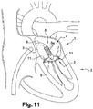
figure 11 illustre le cœur et le retrait de l'organe d'appui ; - la
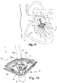
figure 12 illustre le cœur avec l'anneau de renfort fixé sur l'anneau mitral ; - la
figure 13 illustre un cœur et l'introduction, dans l'oreillette gauche du cœur, d'un l'organe d'appui du dispositif selon une deuxième forme de réalisation de l'invention - la
figure 14 illustre en détail de l'organe d'appui de lafigure 13 , en position repliée ; - la
figure 15 illustre le cœur et le déploiement de l'organe d'appui et son positionnement en appui sous la valve mitrale, avec des pièces de textile en feutre ou téflon disposées à l'extrémité des bras de l'organe d'appui et plaquées sous l'anneau mitral ; - la
figure 16 illustre en détail l'organe d'appui en position déployée ; - la
figure 17 illustre le cœur et le déploiement de organe de contre-appui du dispositif, pour le positionnement d'un anneau de renfort sur l'anneau mitral en contre-appui de l'organe d'appui ; - la
figure 18 illustre en détail l'organe de contre-appui et l'organe d'appui en positions déployées ; - la
figure 19 illustre le cœur et le déploiement des bras que comprennent les moyens d'extractions de sutures, en correspondance avec les bras de l'organe de contre-appui ; - la
figure 20 illustre en détail le déploiement des bras des moyens d'extraction conformément à lafigure 19 ; - la
figure 21 illustre le retrait des moyens d'extraction de sutures, après libération desdites sutures et fixation de l'anneau de renfort sur l'anneau mitral ; - la
figure 22 illustre le retrait de l'organe de contre-appui ; - la
figure 23 illustre le retrait de l'organe d'appui ; - la
figure 24 illustre le cœur avec l'anneau de renfort fixé sur l'anneau mitral en contre-appui avec les pièces de textile plaquées de l'autre côté de l'anneau mitral pour sa protection ; - les
figures 25, 26 et 27 illustrent, en perspective, différentes formes de réalisation possibles des sutures de fixation de l'anneau de renfort.
- the
figure 1 illustrates a heart and the introduction, into the left atrium of the heart, of a support member of the device according to a first embodiment of the invention; - the
figure 2 illustrates in detail the support member of thefigure 1 , in folded position; - the
figure 3 illustrates the heart and the deployment of the support member and its positioning in support under the mitral valve; - the
figure 4 illustrates in detail the support member in the deployed position; - the
figure 5 illustrates the heart and the deployment of a counter-support member of the device, for the positioning of a reinforcing ring on the mitral ring in counter-support of the support member; - the
figure 6 illustrates the extraction of the needles arranged inside the arms of the support member, making it possible to release sutures for fixing the reinforcing ring; - the
figure 7 illustrates the release of sutures through the needles of thefigure 6 ; - the
figure 8 illustrates the disengagement between the arms of the counter-support member and the reinforcing ring, in particular by sliding a carriage; - the
figure 9 illustrates the withdrawal of the counter-support member; - the
figure 10 illustrates the heart and the withdrawal of the counter-bearing member according to thefigure 9 ; - the
figure 11 illustrates the heart and the withdrawal of the supporting organ; - the
figure 12 illustrates the heart with the reinforcement ring attached to the mitral ring; - the
figure 13 illustrates a heart and the introduction, into the left atrium of the heart, of a support member of the device according to a second embodiment of the invention - the
figure 14 illustrates in detail the support member of thefigure 13 , in folded position; - the
figure 15 illustrates the heart and the deployment of the support member and its positioning in support under the mitral valve, with pieces of felt or Teflon textile arranged at the end of the arms of the support member and placed under the 'mitral ring; - the
figure 16 illustrates in detail the support member in the deployed position; - the
figure 17 illustrates the heart and the deployment of the counter-support member of the device, for the positioning of a reinforcing ring on the mitral ring against the support member; - the
figure 18 illustrates in detail the counter-support member and the support member in deployed positions; - the
figure 19 illustrates the heart and the deployment of the arms that include the suture extraction means, in correspondence with the arms of the counter-support member; - the
figure 20 illustrates in detail the deployment of the arms of the extraction means in accordance withfigure 19 ; - the
figure 21 illustrates the withdrawal of the suture extraction means, after releasing said sutures and fixing the reinforcing ring on the mitral ring; - the
figure 22 illustrates the withdrawal of the counter-support member; - the
figure 23 illustrates the withdrawal of the support member; - the
figure 24 illustrates the heart with the reinforcement ring fixed on the mitral ring in counter-support with the pieces of textile plated on the other side of the mitral ring for its protection; - the
figures 25, 26 and 27 illustrate, in perspective, various possible embodiments of the sutures for fixing the reinforcing ring.
Le dispositif (1) selon l'invention permet de réaliser une opération chirurgicale, dite d'annuloplastie mitrale, consistant à réparer l'anneau mitral (2) du cœur (3) d'un patient atteint d'une fuite mitrale. Le dispositif permet également de préparer une opération d'annuloplastie ultérieure en permettant la mise en place d'un anneau de renfort sous la forme d'un anneau préventif, dit de préparation ou d'accroche, destiné à recevoir ultérieurement un implant de valve mitrale.The device (1) according to the invention makes it possible to perform a surgical operation, called a mitral annuloplasty, consisting in repairing the mitral annulus (2) of the heart (3) of a patient suffering from a mitral leak. The device also makes it possible to prepare a subsequent annuloplasty operation by allowing the placement of a reinforcing ring in the form of a preventive ring, called preparation or attachment ring, intended to subsequently receive a mitral valve implant. .
Le dispositif (1) selon l'invention est destiné à être positionné dans un introducteur étanche de tout type connu et approprié (non représenté) et d'un diamètre inférieur ou égal à 8 mm, disposé dans une veine fémorale pour remonter et pénétrer dans l'oreillette gauche (4) du cœur (3) en passant par sa paroi septale (5).The device (1) according to the invention is intended to be positioned in a sealed introducer of any known and appropriate type (not shown) and with a diameter less than or equal to 8 mm, placed in a femoral vein in order to ascend and penetrate into it. the left atrium (4) of the heart (3) passing through its septal wall (5).
Le dispositif (1) comprend une tige (6) de manipulation, à l'extrémité de laquelle est agencé un ensemble pour la mise en place et la fixation d'un anneau de renfort (7), par exemple en textile, au niveau de la valve mitrale. L'autre extrémité de la tige (6) est destinée à coopérer avec une poignée assujettie à des moyens de commande, non représentés, par exemple sous la forme d'une gâchette, pour l'actionnement de l'ensemble.The device (1) comprises a handling rod (6), at the end of which is arranged an assembly for the establishment and fixing of a reinforcing ring (7), for example made of textile, at the level of the mitral valve. The other end of the rod (6) is intended to cooperate with a handle subject to control means, not shown, for example in the form of a trigger, for actuating the assembly.
Le dispositif (1) selon l'invention permet, sous contrôle radiographique, après avoir remonté la veine cave, de faire pénétrer l'ensemble dans l'oreillette gauche (4) du cœur (3) en passant au travers de la paroi septale (5). Ensuite, lorsque l'ensemble se trouve dans l'oreillette gauche (4) du cœur (3), il est apte à passer au travers de la valve mitrale pour venir se déployer côté ventricule en dessous de ladite valve mitrale et prendre appui sous l'anneau mitral (2).The device (1) according to the invention makes it possible, under radiographic control, after having ascended the vena cava, to make the assembly penetrate into the left atrium (4) of the heart (3) by passing through the septal wall ( 5). Then, when the assembly is in the left atrium (4) of the heart (3), it is able to pass through the mitral valve to come and deploy on the ventricle side below said mitral valve and take support under the mitral ring (2).
A partir de ce concept, deux formes de réalisation ont été réalisées, à savoir une première forme de réalisation illustrée aux
En référence aux
Ensuite, par traction sur la tige (6) et l'organe d'appui (8), les bras (8a) trouvent naturellement leur chemin à travers les cordages de la valve mitrale pour venir se placer juste en dessous de l'anneau mitral (2) de la valve mitrale, dans l'angle formé par les feuillets et la paroi cardiaque, pour y prendre appui de manière uniformément répartie le long de la périphérie de la valve mitrale, et y exercer une pression, voir
Dans la deuxième forme de réalisation de l'invention, chacune des extrémités libres des bras (8a) de l'organe d'appui (8) est conformée, par exemple en forme de boucle, pour chacune recevoir une pièce de textile (10) en feutre ou téflon, connue de l'homme du métier sous le terme anglais « pledget ». Les pièces de textile (10) sont destinées à être plaquées sous l'anneau mitral (2) et à être fixées par des sutures (11) en contre-appui de l'anneau de renfort (7), tel qu'il sera décrit plus bas.In the second embodiment of the invention, each of the free ends of the arms (8a) of the support member (8) is shaped, for example in the form of a loop, each to receive a piece of textile (10). made of felt or Teflon, known to those skilled in the art under the English term "pledget". The pieces of textile (10) are intended to be pressed under the mitral ring (2) and to be fixed by sutures (11) against the support of the reinforcing ring (7), as will be described. lower.
Dans les deux formes de réalisation, les bras (8a) de l'organe d'appui (8) sont déployés manuellement, soit tous ensemble, soit de manière sélective et indépendamment les uns des autres pour passer plus facilement les cordages de l'appareil mitral et s'adapter à la géométrie de l'anneau mitral (2). Pour s'adapter davantage à la géométrie de l'anneau mitral (2), qui n'est pas forcément circulaire, les bras (8a) sont télescopiques pour présenter des longueurs différentes.In both embodiments, the arms (8a) of the support member (8) are deployed manually, either all together or selectively and independently of each other to more easily pass the ropes of the device. mitral ring and adapt to the geometry of the mitral ring (2). To better adapt to the geometry of the mitral ring (2), which is not necessarily circular, the arms (8a) are telescopic to have different lengths.
Selon une première variante, les bras (8a) peuvent être déployés par des moyens mécaniques (non représentés) que comprennent les moyens de commande. Par exemple, le vissage d'une molette peut permettre de déployer les bras (8a). Dans une autre variante, les bras (8a) sont auto-expansibles et sont insérés dans un fourreau (non représenté) lorsqu'ils sont dans la position repliée, et sont extraits dudit fourreau dans la position déployée. L'ogive (9) a-traumatique peut faire office de fourreau. Dans cette dernière configuration, les bras (8a) sont reliés de manière articulée à un support, tel qu'une douille, monté coulissant sur la tige (6) pour venir se loger dans l'ogive (9) en position repliée des bras (8a).According to a first variant, the arms (8a) can be deployed by mechanical means (not shown) which include the control means. For example, screwing in a thumbwheel can allow the arms (8a) to be deployed. In another variant, the arms (8a) are self-expanding and are inserted into a sleeve (not shown) when they are in the folded position, and are extracted from said sleeve in the deployed position. The a-traumatic warhead (9) can act as a sheath. In the latter configuration, the arms (8a) are hingedly connected to a support, such as a socket, slidably mounted on the rod (6) to come to be housed in the ogive (9) in the folded position of the arms ( 8a).
En référence aux
Les bras (12a) de l'organe de contre-appui (12) sont reliés de manière pivotante à un support (13), tel qu'une douille, disposé coaxialement à la tige (6) et monté avec capacité de coulissement le long de celle-ci. Les bras (12a) de l'organe de contre-appui (12) sont articulés et montés pivotants de sorte à passer, sous l'action des moyens de commande, d'une position repliée le long de la tige (6) à une position déployée écartée de la tige (6) pour réaliser le contre-appui sur l'anneau mitral (2) et positionner l'anneau de renfort (7) en contre-pression et au droit des bras (8a) de l'organe d'appui (8). De la même manière que pour les bras (8a) de l'organe d'appui (8), les bras (12a) de l'organe de contre-appui (12) peuvent être déployés simultanément ou de manière sélective et indépendamment les uns des autres, être télescopiques, et être auto-expansibles et agencés dans un fourreau dans leur position repliée.The arms (12a) of the counter-support member (12) are pivotally connected to a support (13), such as a bushing, disposed coaxially with the rod (6) and mounted with the ability to slide along of it. The arms (12a) of the counter-support member (12) are articulated and pivotably mounted so as to pass, under the action of the control means, from a folded position along the rod (6) to a deployed position away from the rod (6) to make the counter-support on the mitral ring (2) and position the reinforcing ring (7) in counter-pressure and in line with the arms (8a) of the organ d 'support (8). In the same way as for the arms (8a) of the support member (8), the arms (12a) of the counter-support member (12) can be deployed simultaneously or selectively and independently of each other. others, be telescopic, and be self-expanding and arranged in a sleeve in their folded position.
De ce qui précède, les bras (8a) de l'organe d'appui (8) et les bras (12a) de l'organe de contre-appui (12) s'ouvrent à la manière d'un parapluie et viennent en correspondance de part et d'autre de l'anneau mitral (2) pour former un appui/contre-appui. Cette caractéristique permet ensuite de percer l'anneau mitral (2) de façon simple, idéale et sans traction pour fixer l'anneau de renfort (7), tel qu'il sera décrit plus bas, par l'intermédiaire de moyens (14) d'extraction de sutures (11).From the above, the arms (8a) of the support member (8) and the arms (12a) of the counter-support member (12) open like an umbrella and come in correspondence on either side of the mitral ring (2) to form a support / counter-support. This characteristic then makes it possible to pierce the mitral ring (2) in a simple, ideal way and without traction to fix the reinforcement ring (7), as will be described below, by means of means (14) suture extraction (11).
Comme évoqué plus haut, les deux formes de réalisation présentées diffèrent par la technique de fixation de l'anneau de renfort (7).As mentioned above, the two embodiments presented differ in the technique of fixing the reinforcing ring (7).
Selon la première forme de réalisation, et en référence aux
Selon un premier exemple de mise en œuvre, les aiguilles (15) sont destinées à être extraites pour percer l'anneau mitral (2) et faire saillie de la face de dessus de l'anneau mitral (2), en débouchant à l'intérieur des doigts (12d) et des fourches (12b) des bras (12a) correspondants de l'organe de contre-appui (12). Ensuite, chaque suture (11) sous la forme d'un fil (11a) réalisé dans un matériau à mémoire de forme va automatiquement, après avoir été libéré de l'aiguille (15), être déformé pour créer une boucle d'ancrage autour de l'anneau de renfort (7) et dans l'épaisseur de l'anneau mitral (2) pour permettre la fixation dudit anneau de renfort (7) sur l'anneau mitral (2).According to a first example of implementation, the needles (15) are intended to be extracted to pierce the mitral ring (2) and protrude from the top face of the mitral ring (2), opening out at the inside the fingers (12d) and forks (12b) of the corresponding arms (12a) of the counter-support member (12). Then, each suture (11) in the form of a thread (11a) made of a shape memory material will automatically, after being released from the needle (15), be deformed to create an anchor loop around of the reinforcement ring (7) and in the thickness of the mitral ring (2) to allow the attachment of said reinforcement ring (7) to the mitral ring (2).
Selon un deuxième exemple de mise en œuvre, les aiguilles (15) ne percent pas l'anneau mitral (2) et délivrent des sutures (11) sous la forme d'agrafes (11b) qui sont conformées en pointe pour traverser d'elles même l'anneau mitral (2) et l'anneau de renfort (7), et qui comprennent des parties d'ancrage (11c), telles que des extrémités en arpon, pour interdire le retrait desdites agrafes (11b) et verrouiller la fixation de l'anneau de renfort (7) sur l'anneau mitral (2). Des exemples de réalisation des différentes agrafes (11b) et du fil (11a) sont illustrées
Selon la deuxième forme de réalisation, et en référence aux
Lorsque les bras (14a) des moyens (14) d'extraction sont en position déployée, ils se trouvent en correspondance avec les bras (12a) de l'organe de contre-appui (12). Pour permettre la fixation de l'anneau de renfort (7), chaque bras (14a) comprend intérieurement, et de la même manière que pour la première forme de réalisation, une aiguille (15) pour délivrer une suture sous la forme d'un fil (11a) ou d'une agrafe (11b) prévue pour s'ancrer sur la périphérie de la valve mitrale et y fixer l'anneau de renfort (7). Le fonctionnement est identique et n'est pas décrit de nouveau. Dans cette forme de réalisation, les sutures (11) viennent fixer les pièces de textile (10) en renfort et en contre-appui de l'anneau de renfort (7), et de l'autre côté de l'anneau mitral (2). Les pièces de textiles (10) forment des renforts pour les sutures (11), de sorte que la tension de la suture (11) est répartie sur l'ensemble de la pièce de textile (10), et non directement sur l'anneau mitral (2). Les pièces de textile (10) assurent une protection contre les traumatismes dus à la tension de la suture (11).When the arms (14a) of the extraction means (14) are in the deployed position, they are in correspondence with the arms (12a) of the counter-support member (12). To allow the attachment of the reinforcement ring (7), each arm (14a) comprises internally, and in the same manner as for the first embodiment, a needle (15) for delivering a suture in the form of a wire (11a) or a clip (11b) designed to be anchored on the periphery of the mitral valve and to fix the reinforcing ring (7) there. The operation is identical and is not described again. In this embodiment, the sutures (11) fix the pieces of textile (10) in reinforcement and against the support of the reinforcement ring (7), and on the other side of the mitral ring (2 ). The pieces of textile (10) form reinforcements for the sutures (11), so that the tension of the suture (11) is distributed over the entire piece of textile (10), not directly over the ring mitral (2). The textile pieces (10) provide protection against trauma due to the tension of the suture (11).
De la même manière que pour les bras (8a) de l'organe d'appui (8) ou les bras (12a) de l'organe de contre-appui (12), les bras (14a) des moyens (14) d'extraction peuvent être déployés simultanément ou de manière sélective et indépendamment les uns des autres, être télescopiques, et être auto-expansibles et agencé dans un fourreau dans leur position repliée.In the same way as for the arms (8a) of the support member (8) or the arms (12a) of the counter-support member (12), the arms (14a) of the means (14) d The extractors can be deployed simultaneously or selectively and independently of each other, be telescopic, and be self-expanding and arranged in a sheath in their folded position.
En référence à la
En référence aux
L'anneau de renfort (7) constitue un implant prothétique apte à diminuer le calibre de l'anneau mitral (2) pour diminuer, voire supprimer les fuites mitrales. Suivant une autre caractéristique importante, l'anneau de renfort (7) est assujetti à un moyen (non représenté) apte à permettre de réduire sa circonférence après sa mise en place et fixation sur la périphérie de l'anneau mitral (2), comme indiqué. Par exemple, ces moyens sont constitués par un cordon de traction monté librement en translation et à libre coulissement dans l'âme centrale de l'anneau de renfort (7) pour permettre, sous un effet de traction, d'assurer le fronçage de l'anneau et, par conséquent, la diminution de son diamètre. Ces dispositions sont particulièrement importantes pour permettre après la fixation de l'anneau de renfort (7) dans les conditions indiquées, de parfaitement adapter le diamètre de l'implant en s'assurant qu'il n'y a plus aucune fuite.The reinforcing ring (7) constitutes a prosthetic implant capable of reducing the caliber of the mitral ring (2) in order to reduce or even eliminate mitral leaks. According to another important characteristic, the reinforcing ring (7) is subject to a means (not shown) capable of making it possible to reduce its circumference after it has been placed and fixed on the periphery of the mitral ring (2), such as indicated. For example, these means are constituted by a traction cord mounted freely in translation and to slide freely in the central core of the reinforcing ring (7) to allow, under a traction effect, to ensure the gathering of the 'ring and, consequently, the decrease in its diameter. These arrangements are particularly important in order to allow, after fixing the reinforcing ring (7) under the conditions indicated, to perfectly adapt the diameter of the implant while ensuring that there is no longer any leakage.
Dans ce but, le chirurgien retire le dispositif (1), et seules dépassent de l'introducteur, les deux extrémités du fil (11a) qui constitue l'âme axiale de l'anneau. Sous contrôle radio, en exerçant une simple fraction sur le fil, on provoque de manière concomitante le serrage de l'anneau de la valve. Après avoir trouvé la bonne tension correspondant au bon diamètre, le fil peut être serti au moyen d'un nœud ou d'un clip, puis coupé.For this purpose, the surgeon removes the device (1), and only the two ends of the wire (11a) which constitutes the axial core of the ring protrude from the introducer. Under radio control, by exerting a simple fraction on the wire, one causes concomitantly the tightening of the ring of the valve. After finding the right tension for the right diameter, the wire can be crimped with a knot or clip and then cut.
Les caractéristiques du dispositif (1) selon l'invention apportent de nombreux avantages par rapport aux solutions existantes. Le fait de passer par la voie transfémorale permet de réduire la durée et le caractère invasif de l'opération. Avec une coupe échographique bidimensionnelle de la jonction auriculo ventriculaire, il est possible de visualiser l'enclavement souhaité du dispositif (1) sur la petite valve mitrale du côté ventriculaire. La mise en place est guidée par l'anatomie même des tissus et de la résistance que l'opérateur perçoit en position de butée de l'organe d'appui (8) et de l'organe de contre-appui (12)The characteristics of the device (1) according to the invention provide numerous advantages over existing solutions. The fact of passing by the transfemoral route makes it possible to reduce the duration and the invasiveness of the operation. With a two-dimensional ultrasound section of the atrioventricular junction, it is possible to visualize the desired entrapment of the device (1) on the small mitral valve on the ventricular side. The installation is guided by the anatomy of the tissues and the resistance that the operator perceives in the abutment position of the support member (8) and the counter-support member (12)
A noter également que le dispositif (1) permet d'exercer deux forces d'appui et de contre-appui opposées pour effectuer la perforation des tissus et le passage des sutures (11) d'ancrage sans risque de fragiliser ledit tissu en supprimant tout risque de tâtonnement. Autrement dit, le tissu de l'anneau mitral (2) et les tissus adjacents sont perforés plus efficacement en une seule fois avec une tenue optimale des sutures (11).It should also be noted that the device (1) makes it possible to exert two opposing support and counter-support forces to perform the perforation of the tissues and the passage of the sutures (11) anchoring without risk of weakening said fabric by eliminating any risk of trial and error. In other words, mitral annulus tissue (2) and adjacent tissues are punctured more efficiently in one go with optimal suture hold (11).
A noter enfin que les bras (8a) de l'organe d'appui (8) et/ou les bras (12a) de l'organe de contre-appui (12) et/ou les bras (14a) des moyens (14) d'extraction comprennent chacun un marqueur radio-opaque et/ou échographique permettant au chirurgien d'effectuer un contrôle en 2D ou en 3D de leur position au fur et à mesure de l'opération.Finally, it should be noted that the arms (8a) of the support member (8) and / or the arms (12a) of the counter-support member (12) and / or the arms (14a) of the means (14 ) extraction each comprise a radiopaque and / or echographic marker allowing the surgeon to carry out a 2D or 3D check of their position as the operation progresses.
Claims (10)
- Device (1) for performing or preparing a transfemoral annuloplasty of the mitral valve of a heart, and intended to be positioned in a sealed introducer placed in a femoral vein to penetrate the left atrium of the heart through its septal wall, comprising an assembly for cooperating with a handle under the control of a control means for actuating the assembly for placing and attaching a reinforcement ring (7) on the mitral annulus, with said assembly arranged at the end of a handling rod (6) and comprising:- a bearing member (8) comprising a plurality of arms (8a) able to provide support under the mitral annulus (2) in a manner uniformly distributed along the periphery of the mitral valve;- a counter-bearing member (12) comprising a plurality of arms (12a), at the free end of which arms the reinforcement ring (7) is arranged, with the arms (12a) connected pivotably to a support (13) disposed coaxially with respect to the rod (6) in such a way as to change, under the action of the control means, from a position folded along the rod (6) to a deployed position spaced away from the rod (6) in order to realize the countersupport on the mitral annulus and position the reinforcement ring (7);characterized in that the plurality of arms (8a) are connected pivotably to the end of the rod (6) so as to change, under the action of the control means, from a position folded along the rod (6) to a deployed position spaced away from the rod (6), and in that the assembly comprises means (14) for removing sutures (11) to attach the reinforcement ring (7) to the mitral annulus.
- Device (1) according to claim 1, characterized in that the arms (8a) of the bearing member (8) and/or the arms (12a) of the counter-bearing member (12) are connected pivotably to a support (13) disposed coaxially with respect to the rod (6) in such a way as to change, under the action of the control means, simultaneously or selectively and independently from each other, from the folded position to the deployed position.
- Device (1) according to claim 1, characterized in that the arms (8a) of the bearing member (8) and/or the arms (12a) of the counter-bearing member (12) are arranged inside a sheath in the folded position, and are pushed out of the sheath and are self-expanding in the deployed position.
- Device (1) according to claim 1, characterized in that the arms (8a) of the bearing member (8) and/or the arms (12a) of the counter-bearing member (12) each include a radiopaque and/or ultrasound marker.
- Device (1) according to claim 1, characterized in that the arms (8a) of the bearing member (8) and/or the arms (12a) of the counter-bearing member (12) are telescopic.
- Device (1) according to claim 1, characterized in that the means (14) to allow the extraction of sutures (11) comprise a plurality of arms (14a) connected pivotably to a support (15) disposed coaxially to the rod (6) so as to change, under the action of the control means, from a folded position along the rod (6) to a deployed position spaced away from the rod (6) that aligns with the arms (12a) of the counter-bearing member (12), each arm (14a) internally comprising an extractable suture (11) to anchor on the periphery of the mitral valve and to fix the reinforcement ring thereto (7).
- Device (1) according to claim 1, characterized in that each arm (8a) of the bearing member (8) is curved, articulated, or flexible to facilitate its passage through the tendinous cords of the mitral valve.
- Device (1) according to claim 1, characterized in that the end of each arm (8a) may be composed of several branches, which can move away from each other after passing through the mitral valve cords to form several support points under the mitral annulus.
- Device (1) according to claim 1, characterized in that each arm (8a) of the bearing member (8) internally comprises an extractable suture (11) to go through the mitral annulus and attach the reinforcement ring (7).
- Device (1) according to claim 6, characterized in that the free end of each arm (8a) of the bearing member (8) comprises a piece of felt or Teflon fabric (10) intended to be laid under the mitral valve and fixed by the sutures (11) to support and counter-bear against the reinforcement ring (7).
Applications Claiming Priority (2)
| Application Number | Priority Date | Filing Date | Title |
|---|---|---|---|
| FR1662559A FR3060292B1 (en) | 2016-12-15 | 2016-12-15 | DEVICE FOR REALIZING OR PREPARING MITRAL ANNULOPLASTY BY TRANSFEMORAL PATHWAY |
| PCT/FR2017/053444 WO2018109329A1 (en) | 2016-12-15 | 2017-12-07 | Device for performing or preparing for a mitral valve annuloplasty by a transfemoral approach |
Publications (2)
| Publication Number | Publication Date |
|---|---|
| EP3554423A1 EP3554423A1 (en) | 2019-10-23 |
| EP3554423B1 true EP3554423B1 (en) | 2020-08-05 |
Family
ID=58645149
Family Applications (1)
| Application Number | Title | Priority Date | Filing Date |
|---|---|---|---|
| EP17822385.5A Active EP3554423B1 (en) | 2016-12-15 | 2017-12-07 | Device for performing or preparing for a mitral valve annuloplasty by a transfemoral approach |
Country Status (5)
| Country | Link |
|---|---|
| US (1) | US11020230B2 (en) |
| EP (1) | EP3554423B1 (en) |
| FR (1) | FR3060292B1 (en) |
| IL (1) | IL267339A (en) |
| WO (1) | WO2018109329A1 (en) |
Cited By (23)
| Publication number | Priority date | Publication date | Assignee | Title |
|---|---|---|---|---|
| US10940001B2 (en) | 2012-05-30 | 2021-03-09 | Neovasc Tiara Inc. | Methods and apparatus for loading a prosthesis onto a delivery system |
| US11311376B2 (en) | 2019-06-20 | 2022-04-26 | Neovase Tiara Inc. | Low profile prosthetic mitral valve |
| US11357622B2 (en) | 2016-01-29 | 2022-06-14 | Neovase Tiara Inc. | Prosthetic valve for avoiding obstruction of outflow |
| US11389291B2 (en) | 2013-04-04 | 2022-07-19 | Neovase Tiara Inc. | Methods and apparatus for delivering a prosthetic valve to a beating heart |
| US11413139B2 (en) | 2011-11-23 | 2022-08-16 | Neovasc Tiara Inc. | Sequentially deployed transcatheter mitral valve prosthesis |
| US11419720B2 (en) | 2010-05-05 | 2022-08-23 | Neovasc Tiara Inc. | Transcatheter mitral valve prosthesis |
| US11464631B2 (en) | 2016-11-21 | 2022-10-11 | Neovasc Tiara Inc. | Methods and systems for rapid retraction of a transcatheter heart valve delivery system |
| US11471282B2 (en) | 2019-03-19 | 2022-10-18 | Shifamed Holdings, Llc | Prosthetic cardiac valve devices, systems, and methods |
| US11491006B2 (en) | 2019-04-10 | 2022-11-08 | Neovasc Tiara Inc. | Prosthetic valve with natural blood flow |
| US11497602B2 (en) | 2012-02-14 | 2022-11-15 | Neovasc Tiara Inc. | Methods and apparatus for engaging a valve prosthesis with tissue |
| US11602429B2 (en) | 2019-04-01 | 2023-03-14 | Neovasc Tiara Inc. | Controllably deployable prosthetic valve |
| US11672657B2 (en) | 2018-10-05 | 2023-06-13 | Shifamed Holdings, Llc | Prosthetic cardiac valve devices, systems, and methods |
| US11737872B2 (en) | 2018-11-08 | 2023-08-29 | Neovasc Tiara Inc. | Ventricular deployment of a transcatheter mitral valve prosthesis |
| US11779742B2 (en) | 2019-05-20 | 2023-10-10 | Neovasc Tiara Inc. | Introducer with hemostasis mechanism |
| US11793640B2 (en) | 2017-08-25 | 2023-10-24 | Neovasc Tiara Inc. | Sequentially deployed transcatheter mitral valve prosthesis |
| US11833034B2 (en) | 2016-01-13 | 2023-12-05 | Shifamed Holdings, Llc | Prosthetic cardiac valve devices, systems, and methods |
| US11998447B2 (en) | 2019-03-08 | 2024-06-04 | Neovasc Tiara Inc. | Retrievable prosthesis delivery system |
| US12053371B2 (en) | 2020-08-31 | 2024-08-06 | Shifamed Holdings, Llc | Prosthetic valve delivery system |
| US12109111B2 (en) | 2015-12-15 | 2024-10-08 | Neovasc Tiara Inc. | Transseptal delivery system |
| US12201521B2 (en) | 2021-03-22 | 2025-01-21 | Shifamed Holdings, Llc | Anchor position verification for prosthetic cardiac valve devices |
| US12290456B2 (en) | 2018-08-21 | 2025-05-06 | Shifamed Holdings, Llc | Prosthetic cardiac valve devices, systems, and methods |
| US12329635B2 (en) | 2020-12-04 | 2025-06-17 | Shifamed Holdings, Llc | Flared prosthetic cardiac valve delivery devices and systems |
| US12403008B2 (en) | 2018-10-19 | 2025-09-02 | Shifamed Holdings, Llc | Adjustable medical device |
Families Citing this family (12)
| Publication number | Priority date | Publication date | Assignee | Title |
|---|---|---|---|---|
| US10500038B1 (en) | 2011-05-20 | 2019-12-10 | Tel Hashomer Medical Research Infrastructure And Services Ltd. | Prosthetic mitral valve, and methods and devices for deploying the prosthetic mitral valve |
| LT2852354T (en) | 2012-05-20 | 2020-09-25 | Tel Hashomer Medical Research Infrastructure And Services Ltd. | MITRAL VALVE PROSTHESIS |
| US20200146854A1 (en) | 2016-05-16 | 2020-05-14 | Elixir Medical Corporation | Methods and devices for heart valve repair |
| FR3060292B1 (en) | 2016-12-15 | 2019-01-25 | Cmi'nov | DEVICE FOR REALIZING OR PREPARING MITRAL ANNULOPLASTY BY TRANSFEMORAL PATHWAY |
| EP3417831B2 (en) * | 2017-06-19 | 2023-05-24 | HVR Cardio Oy | Delivery device for an annuloplasty implant |
| EP3796876B1 (en) | 2018-05-22 | 2022-07-27 | Boston Scientific Scimed, Inc. | Percutaneous papillary muscle relocation |
| US12350156B2 (en) | 2018-11-14 | 2025-07-08 | Sheba Impact Ltd. | Atrioventricular valve repair |
| US11559397B2 (en) * | 2018-12-13 | 2023-01-24 | Medtronic Vascular, Inc. | Heart valve repair |
| ES2952581T3 (en) | 2019-08-14 | 2023-11-02 | Innovalve Bio Medical Ltd | Atrioventricular valve replacement |
| CN112656546B (en) * | 2020-12-25 | 2022-09-20 | 上海易桥医疗器械有限公司 | Valve clamping device and valve clamping system |
| CN117157033A (en) * | 2021-02-09 | 2023-12-01 | 爱德华兹生命科学创新(以色列)有限公司 | System and apparatus for heart valve repair |
| US12447017B2 (en) * | 2021-03-11 | 2025-10-21 | St. Jude Medical, Cardiology Division, Inc. | Delivery system radiopaque (RO) markers for TAVR commissure alignment |
Family Cites Families (28)
| Publication number | Priority date | Publication date | Assignee | Title |
|---|---|---|---|---|
| US8246671B2 (en) * | 1999-08-09 | 2012-08-21 | Cardiokinetix, Inc. | Retrievable cardiac devices |
| US8758372B2 (en) * | 2002-08-29 | 2014-06-24 | St. Jude Medical, Cardiology Division, Inc. | Implantable devices for controlling the size and shape of an anatomical structure or lumen |
| WO2007136783A2 (en) * | 2002-08-29 | 2007-11-29 | Mitralsolutions, Inc. | Implantable devices for controlling the size and shape of an anatomical structure or lumen |
| US7175656B2 (en) * | 2003-04-18 | 2007-02-13 | Alexander Khairkhahan | Percutaneous transcatheter heart valve replacement |
| WO2005009285A2 (en) * | 2003-07-21 | 2005-02-03 | The Trustees Of The University Of Pennsylvania | Percutaneous heart valve |
| US20060074483A1 (en) * | 2004-10-01 | 2006-04-06 | Schrayer Howard L | Method of treatment and devices for the treatment of left ventricular failure |
| SE531468C2 (en) * | 2005-04-21 | 2009-04-14 | Edwards Lifesciences Ag | An apparatus for controlling blood flow |
| US8430926B2 (en) * | 2006-08-11 | 2013-04-30 | Japd Consulting Inc. | Annuloplasty with enhanced anchoring to the annulus based on tissue healing |
| MX2009007289A (en) * | 2007-01-03 | 2009-09-09 | Mitralsolutions Inc | Implantable devices for controlling the size and shape of an anatomical structure or lumen. |
| US8663217B2 (en) * | 2007-05-29 | 2014-03-04 | Cvdevices, Llc | Devices and systems for valve removal |
| US9504486B2 (en) * | 2010-04-19 | 2016-11-29 | Cvdevices, Llc | Devices, systems, and methods for valve removal |
| AU2008269018B2 (en) * | 2007-06-26 | 2014-07-31 | St. Jude Medical, Inc. | Apparatus and methods for implanting collapsible/expandable prosthetic heart valves |
| BRPI0916696A2 (en) * | 2008-07-29 | 2015-11-17 | St Jude Medical Cardiology Div | method and system for long term adjustment of an implant device |
| EP2389121B1 (en) * | 2009-01-22 | 2020-10-07 | St. Jude Medical, Cardiology Division, Inc. | Post-operative adjustment tool, minimally invasive attachment apparatus, and adjustable tricuspid ring |
| US8845722B2 (en) * | 2009-08-03 | 2014-09-30 | Shlomo Gabbay | Heart valve prosthesis and method of implantation thereof |
| US8357195B2 (en) * | 2010-04-15 | 2013-01-22 | Medtronic, Inc. | Catheter based annuloplasty system and method |
| US9504571B2 (en) * | 2012-06-07 | 2016-11-29 | Edwards Lifesciences Corporation | Systems for implanting annuloplasty rings with microanchors |
| FR2998167B1 (en) | 2013-03-20 | 2015-01-09 | Marco Vola | DEVICE FOR PERFORMING AN ANNULOPLASTY BY THE TRANSAPICAL PATH OF THE MITRAL VALVE |
| US20140296969A1 (en) * | 2013-04-02 | 2014-10-02 | Tendyne Holdlings, Inc. | Anterior Leaflet Clip Device for Prosthetic Mitral Valve |
| US9610159B2 (en) * | 2013-05-30 | 2017-04-04 | Tendyne Holdings, Inc. | Structural members for prosthetic mitral valves |
| CN105392449B (en) * | 2013-06-06 | 2017-09-05 | 戴维·阿隆 | Heart valve repair and replacement |
| EP3182932B1 (en) * | 2014-08-18 | 2019-05-15 | St. Jude Medical, Cardiology Division, Inc. | Annuloplasty ring with sensor |
| US10226335B2 (en) * | 2015-06-22 | 2019-03-12 | Edwards Lifesciences Cardiaq Llc | Actively controllable heart valve implant and method of controlling same |
| US10426619B2 (en) * | 2015-12-30 | 2019-10-01 | Avvie Gmbh | Implant and method for improving coaptation of an atrioventricular valve |
| US9517130B1 (en) * | 2016-05-24 | 2016-12-13 | Cardiac Implants Llc | Implanting a cinching cord into a cardiac valve annulus |
| EP3512465B1 (en) * | 2016-09-15 | 2021-09-01 | Cardiac Implants LLC | An apparatus for delivering a cardiac annulus ring |
| FR3060292B1 (en) | 2016-12-15 | 2019-01-25 | Cmi'nov | DEVICE FOR REALIZING OR PREPARING MITRAL ANNULOPLASTY BY TRANSFEMORAL PATHWAY |
| US11559397B2 (en) * | 2018-12-13 | 2023-01-24 | Medtronic Vascular, Inc. | Heart valve repair |
-
2016
- 2016-12-15 FR FR1662559A patent/FR3060292B1/en not_active Expired - Fee Related
-
2017
- 2017-12-07 WO PCT/FR2017/053444 patent/WO2018109329A1/en not_active Ceased
- 2017-12-07 US US16/469,201 patent/US11020230B2/en not_active Expired - Fee Related
- 2017-12-07 EP EP17822385.5A patent/EP3554423B1/en active Active
-
2019
- 2019-06-13 IL IL267339A patent/IL267339A/en unknown
Non-Patent Citations (1)
| Title |
|---|
| None * |
Cited By (33)
| Publication number | Priority date | Publication date | Assignee | Title |
|---|---|---|---|---|
| US11419720B2 (en) | 2010-05-05 | 2022-08-23 | Neovasc Tiara Inc. | Transcatheter mitral valve prosthesis |
| US11413139B2 (en) | 2011-11-23 | 2022-08-16 | Neovasc Tiara Inc. | Sequentially deployed transcatheter mitral valve prosthesis |
| US12053369B2 (en) | 2011-11-23 | 2024-08-06 | Neovasc Tiara Inc. | Sequentially deployed transcatheter mitral valve prosthesis |
| US12138159B2 (en) | 2012-02-14 | 2024-11-12 | Neovasc Tiara Inc. | Methods and apparatus for engaging a valve prosthesis with tissue |
| US11497602B2 (en) | 2012-02-14 | 2022-11-15 | Neovasc Tiara Inc. | Methods and apparatus for engaging a valve prosthesis with tissue |
| US11389294B2 (en) | 2012-05-30 | 2022-07-19 | Neovasc Tiara Inc. | Methods and apparatus for loading a prosthesis onto a delivery system |
| US10940001B2 (en) | 2012-05-30 | 2021-03-09 | Neovasc Tiara Inc. | Methods and apparatus for loading a prosthesis onto a delivery system |
| US11617650B2 (en) | 2012-05-30 | 2023-04-04 | Neovasc Tiara Inc. | Methods and apparatus for loading a prosthesis onto a delivery system |
| US11389291B2 (en) | 2013-04-04 | 2022-07-19 | Neovase Tiara Inc. | Methods and apparatus for delivering a prosthetic valve to a beating heart |
| US12109111B2 (en) | 2015-12-15 | 2024-10-08 | Neovasc Tiara Inc. | Transseptal delivery system |
| US11833034B2 (en) | 2016-01-13 | 2023-12-05 | Shifamed Holdings, Llc | Prosthetic cardiac valve devices, systems, and methods |
| US11357622B2 (en) | 2016-01-29 | 2022-06-14 | Neovase Tiara Inc. | Prosthetic valve for avoiding obstruction of outflow |
| US12193932B2 (en) | 2016-01-29 | 2025-01-14 | Neovasc Tiara Inc. | Prosthetic valve for avoiding obstruction of outflow |
| US11464631B2 (en) | 2016-11-21 | 2022-10-11 | Neovasc Tiara Inc. | Methods and systems for rapid retraction of a transcatheter heart valve delivery system |
| US12201524B2 (en) | 2016-11-21 | 2025-01-21 | Neovasc Tiara Inc. | Methods and systems for rapid retraction of a transcatheter heart valve delivery system |
| US11793640B2 (en) | 2017-08-25 | 2023-10-24 | Neovasc Tiara Inc. | Sequentially deployed transcatheter mitral valve prosthesis |
| US12290456B2 (en) | 2018-08-21 | 2025-05-06 | Shifamed Holdings, Llc | Prosthetic cardiac valve devices, systems, and methods |
| US12419743B2 (en) | 2018-10-05 | 2025-09-23 | Shifamed Holdings, Llc | Prosthetic cardiac valve devices, systems, and methods |
| US11986389B2 (en) | 2018-10-05 | 2024-05-21 | Shifamed Holdings, Llc | Prosthetic cardiac valve devices, systems, and methods |
| US11672657B2 (en) | 2018-10-05 | 2023-06-13 | Shifamed Holdings, Llc | Prosthetic cardiac valve devices, systems, and methods |
| US12403008B2 (en) | 2018-10-19 | 2025-09-02 | Shifamed Holdings, Llc | Adjustable medical device |
| US11737872B2 (en) | 2018-11-08 | 2023-08-29 | Neovasc Tiara Inc. | Ventricular deployment of a transcatheter mitral valve prosthesis |
| US11998447B2 (en) | 2019-03-08 | 2024-06-04 | Neovasc Tiara Inc. | Retrievable prosthesis delivery system |
| US11471282B2 (en) | 2019-03-19 | 2022-10-18 | Shifamed Holdings, Llc | Prosthetic cardiac valve devices, systems, and methods |
| US11602429B2 (en) | 2019-04-01 | 2023-03-14 | Neovasc Tiara Inc. | Controllably deployable prosthetic valve |
| US11491006B2 (en) | 2019-04-10 | 2022-11-08 | Neovasc Tiara Inc. | Prosthetic valve with natural blood flow |
| US12036117B2 (en) | 2019-04-10 | 2024-07-16 | Neovasc Tiara Inc. | Prosthetic valve with natural blood flow |
| US11779742B2 (en) | 2019-05-20 | 2023-10-10 | Neovasc Tiara Inc. | Introducer with hemostasis mechanism |
| US11311376B2 (en) | 2019-06-20 | 2022-04-26 | Neovase Tiara Inc. | Low profile prosthetic mitral valve |
| US11931254B2 (en) | 2019-06-20 | 2024-03-19 | Neovasc Tiara Inc. | Low profile prosthetic mitral valve |
| US12053371B2 (en) | 2020-08-31 | 2024-08-06 | Shifamed Holdings, Llc | Prosthetic valve delivery system |
| US12329635B2 (en) | 2020-12-04 | 2025-06-17 | Shifamed Holdings, Llc | Flared prosthetic cardiac valve delivery devices and systems |
| US12201521B2 (en) | 2021-03-22 | 2025-01-21 | Shifamed Holdings, Llc | Anchor position verification for prosthetic cardiac valve devices |
Also Published As
| Publication number | Publication date |
|---|---|
| EP3554423A1 (en) | 2019-10-23 |
| US20200100898A1 (en) | 2020-04-02 |
| FR3060292B1 (en) | 2019-01-25 |
| US11020230B2 (en) | 2021-06-01 |
| FR3060292A1 (en) | 2018-06-22 |
| WO2018109329A1 (en) | 2018-06-21 |
| IL267339A (en) | 2019-08-29 |
Similar Documents
| Publication | Publication Date | Title |
|---|---|---|
| EP3554423B1 (en) | Device for performing or preparing for a mitral valve annuloplasty by a transfemoral approach | |
| EP2976043B1 (en) | Device for carrying out a transapical mitral valve annuloplasty | |
| FR3072013B1 (en) | DEVICE FOR SUTURING A CARDIAC VALVULAR PROSTHESIS | |
| EP3573544B1 (en) | Device for transfemoral repair of the mitral valve chordae of a heart | |
| JP6933421B2 (en) | Medical devices and methods for heart valve repair | |
| US10864076B2 (en) | Transapical mitral valve replacement | |
| EP2986255B1 (en) | Implant, intended to be placed in a blood circulation passage, comprising a system for separating the proximal arms | |
| EP2000116B1 (en) | Kit designed to be implanted in a blood vessel | |
| FR3058632A1 (en) | DEVICE FOR TREATING A BIOLOGICAL VALVE WITH PUSH BODY OF THE VALVE | |
| FR3058631A1 (en) | IMPLANT FOR TREATING A BIOLOGICAL VALVE | |
| FR3006884A1 (en) | ATRAUMATIC DEVICE FOR INTRODUCING A HOLLOW TUBULAR ELEMENT IN A BIOLOGICAL ORGAN | |
| CN106999281A (en) | Transcatheter prosthetic heart valves and delivery systems | |
| JP2018531093A6 (en) | Medical instruments and methods for heart valve repair | |
| JP2018531093A (en) | Medical instruments and methods for heart valve repair | |
| WO2016008859A1 (en) | Device for the endovascular treatment of a heart valve in preparation for a percutaneous valve replacement | |
| WO2014056754A1 (en) | Device for treating a blood vessel | |
| FR3020265A1 (en) | DEVICE FOR PLACING A SEAL AROUND AN IMPLANT IN A BLOOD CIRCULATION PASSAGE, AND TREATMENT NECESSARY THEREFOR | |
| FR3023703A1 (en) | DEVICE FOR TREATING A BLOOD CIRCULATION CONDUIT | |
| US12097117B2 (en) | Transcatheter prosthetic heart valve delivery system with distal cutting assembly | |
| WO2018050850A1 (en) | Implantable device for shaping an intracorporeal wall, and associated treatment kit | |
| WO2021064303A1 (en) | Device for placing and fastening a reinforcement implant on a mitral valve of a heart with shape-memory sutures using a transfemoral approach |
Legal Events
| Date | Code | Title | Description |
|---|---|---|---|
| STAA | Information on the status of an ep patent application or granted ep patent |
Free format text: STATUS: UNKNOWN |
|
| STAA | Information on the status of an ep patent application or granted ep patent |
Free format text: STATUS: THE INTERNATIONAL PUBLICATION HAS BEEN MADE |
|
| PUAI | Public reference made under article 153(3) epc to a published international application that has entered the european phase |
Free format text: ORIGINAL CODE: 0009012 |
|
| STAA | Information on the status of an ep patent application or granted ep patent |
Free format text: STATUS: REQUEST FOR EXAMINATION WAS MADE |
|
| 17P | Request for examination filed |
Effective date: 20190613 |
|
| AK | Designated contracting states |
Kind code of ref document: A1 Designated state(s): AL AT BE BG CH CY CZ DE DK EE ES FI FR GB GR HR HU IE IS IT LI LT LU LV MC MK MT NL NO PL PT RO RS SE SI SK SM TR |
|
| AX | Request for extension of the european patent |
Extension state: BA ME |
|
| DAV | Request for validation of the european patent (deleted) | ||
| DAX | Request for extension of the european patent (deleted) | ||
| GRAP | Despatch of communication of intention to grant a patent |
Free format text: ORIGINAL CODE: EPIDOSNIGR1 |
|
| STAA | Information on the status of an ep patent application or granted ep patent |
Free format text: STATUS: GRANT OF PATENT IS INTENDED |
|
| INTG | Intention to grant announced |
Effective date: 20200402 |
|
| GRAS | Grant fee paid |
Free format text: ORIGINAL CODE: EPIDOSNIGR3 |
|
| GRAA | (expected) grant |
Free format text: ORIGINAL CODE: 0009210 |
|
| STAA | Information on the status of an ep patent application or granted ep patent |
Free format text: STATUS: THE PATENT HAS BEEN GRANTED |
|
| AK | Designated contracting states |
Kind code of ref document: B1 Designated state(s): AL AT BE BG CH CY CZ DE DK EE ES FI FR GB GR HR HU IE IS IT LI LT LU LV MC MK MT NL NO PL PT RO RS SE SI SK SM TR |
|
| REG | Reference to a national code |
Ref country code: GB Ref legal event code: FG4D Free format text: NOT ENGLISH |
|
| REG | Reference to a national code |
Ref country code: CH Ref legal event code: EP |
|
| REG | Reference to a national code |
Ref country code: AT Ref legal event code: REF Ref document number: 1297660 Country of ref document: AT Kind code of ref document: T Effective date: 20200815 |
|
| REG | Reference to a national code |
Ref country code: DE Ref legal event code: R096 Ref document number: 602017021340 Country of ref document: DE |
|
| REG | Reference to a national code |
Ref country code: IE Ref legal event code: FG4D Free format text: LANGUAGE OF EP DOCUMENT: FRENCH |
|
| REG | Reference to a national code |
Ref country code: LT Ref legal event code: MG4D |
|
| REG | Reference to a national code |
Ref country code: NL Ref legal event code: MP Effective date: 20200805 |
|
| REG | Reference to a national code |
Ref country code: AT Ref legal event code: MK05 Ref document number: 1297660 Country of ref document: AT Kind code of ref document: T Effective date: 20200805 |
|
| PG25 | Lapsed in a contracting state [announced via postgrant information from national office to epo] |
Ref country code: AT Free format text: LAPSE BECAUSE OF FAILURE TO SUBMIT A TRANSLATION OF THE DESCRIPTION OR TO PAY THE FEE WITHIN THE PRESCRIBED TIME-LIMIT Effective date: 20200805 Ref country code: FI Free format text: LAPSE BECAUSE OF FAILURE TO SUBMIT A TRANSLATION OF THE DESCRIPTION OR TO PAY THE FEE WITHIN THE PRESCRIBED TIME-LIMIT Effective date: 20200805 Ref country code: GR Free format text: LAPSE BECAUSE OF FAILURE TO SUBMIT A TRANSLATION OF THE DESCRIPTION OR TO PAY THE FEE WITHIN THE PRESCRIBED TIME-LIMIT Effective date: 20201106 Ref country code: NO Free format text: LAPSE BECAUSE OF FAILURE TO SUBMIT A TRANSLATION OF THE DESCRIPTION OR TO PAY THE FEE WITHIN THE PRESCRIBED TIME-LIMIT Effective date: 20201105 Ref country code: PT Free format text: LAPSE BECAUSE OF FAILURE TO SUBMIT A TRANSLATION OF THE DESCRIPTION OR TO PAY THE FEE WITHIN THE PRESCRIBED TIME-LIMIT Effective date: 20201207 Ref country code: ES Free format text: LAPSE BECAUSE OF FAILURE TO SUBMIT A TRANSLATION OF THE DESCRIPTION OR TO PAY THE FEE WITHIN THE PRESCRIBED TIME-LIMIT Effective date: 20200805 Ref country code: SE Free format text: LAPSE BECAUSE OF FAILURE TO SUBMIT A TRANSLATION OF THE DESCRIPTION OR TO PAY THE FEE WITHIN THE PRESCRIBED TIME-LIMIT Effective date: 20200805 Ref country code: BG Free format text: LAPSE BECAUSE OF FAILURE TO SUBMIT A TRANSLATION OF THE DESCRIPTION OR TO PAY THE FEE WITHIN THE PRESCRIBED TIME-LIMIT Effective date: 20201105 Ref country code: HR Free format text: LAPSE BECAUSE OF FAILURE TO SUBMIT A TRANSLATION OF THE DESCRIPTION OR TO PAY THE FEE WITHIN THE PRESCRIBED TIME-LIMIT Effective date: 20200805 Ref country code: LT Free format text: LAPSE BECAUSE OF FAILURE TO SUBMIT A TRANSLATION OF THE DESCRIPTION OR TO PAY THE FEE WITHIN THE PRESCRIBED TIME-LIMIT Effective date: 20200805 |
|
| PG25 | Lapsed in a contracting state [announced via postgrant information from national office to epo] |
Ref country code: IS Free format text: LAPSE BECAUSE OF FAILURE TO SUBMIT A TRANSLATION OF THE DESCRIPTION OR TO PAY THE FEE WITHIN THE PRESCRIBED TIME-LIMIT Effective date: 20201205 Ref country code: PL Free format text: LAPSE BECAUSE OF FAILURE TO SUBMIT A TRANSLATION OF THE DESCRIPTION OR TO PAY THE FEE WITHIN THE PRESCRIBED TIME-LIMIT Effective date: 20200805 Ref country code: LV Free format text: LAPSE BECAUSE OF FAILURE TO SUBMIT A TRANSLATION OF THE DESCRIPTION OR TO PAY THE FEE WITHIN THE PRESCRIBED TIME-LIMIT Effective date: 20200805 Ref country code: RS Free format text: LAPSE BECAUSE OF FAILURE TO SUBMIT A TRANSLATION OF THE DESCRIPTION OR TO PAY THE FEE WITHIN THE PRESCRIBED TIME-LIMIT Effective date: 20200805 Ref country code: NL Free format text: LAPSE BECAUSE OF FAILURE TO SUBMIT A TRANSLATION OF THE DESCRIPTION OR TO PAY THE FEE WITHIN THE PRESCRIBED TIME-LIMIT Effective date: 20200805 |
|
| PG25 | Lapsed in a contracting state [announced via postgrant information from national office to epo] |
Ref country code: SM Free format text: LAPSE BECAUSE OF FAILURE TO SUBMIT A TRANSLATION OF THE DESCRIPTION OR TO PAY THE FEE WITHIN THE PRESCRIBED TIME-LIMIT Effective date: 20200805 Ref country code: CZ Free format text: LAPSE BECAUSE OF FAILURE TO SUBMIT A TRANSLATION OF THE DESCRIPTION OR TO PAY THE FEE WITHIN THE PRESCRIBED TIME-LIMIT Effective date: 20200805 Ref country code: DK Free format text: LAPSE BECAUSE OF FAILURE TO SUBMIT A TRANSLATION OF THE DESCRIPTION OR TO PAY THE FEE WITHIN THE PRESCRIBED TIME-LIMIT Effective date: 20200805 Ref country code: RO Free format text: LAPSE BECAUSE OF FAILURE TO SUBMIT A TRANSLATION OF THE DESCRIPTION OR TO PAY THE FEE WITHIN THE PRESCRIBED TIME-LIMIT Effective date: 20200805 Ref country code: EE Free format text: LAPSE BECAUSE OF FAILURE TO SUBMIT A TRANSLATION OF THE DESCRIPTION OR TO PAY THE FEE WITHIN THE PRESCRIBED TIME-LIMIT Effective date: 20200805 |
|
| REG | Reference to a national code |
Ref country code: DE Ref legal event code: R097 Ref document number: 602017021340 Country of ref document: DE |
|
| PG25 | Lapsed in a contracting state [announced via postgrant information from national office to epo] |
Ref country code: AL Free format text: LAPSE BECAUSE OF FAILURE TO SUBMIT A TRANSLATION OF THE DESCRIPTION OR TO PAY THE FEE WITHIN THE PRESCRIBED TIME-LIMIT Effective date: 20200805 |
|
| PLBE | No opposition filed within time limit |
Free format text: ORIGINAL CODE: 0009261 |
|
| STAA | Information on the status of an ep patent application or granted ep patent |
Free format text: STATUS: NO OPPOSITION FILED WITHIN TIME LIMIT |
|
| PG25 | Lapsed in a contracting state [announced via postgrant information from national office to epo] |
Ref country code: SK Free format text: LAPSE BECAUSE OF FAILURE TO SUBMIT A TRANSLATION OF THE DESCRIPTION OR TO PAY THE FEE WITHIN THE PRESCRIBED TIME-LIMIT Effective date: 20200805 |
|
| 26N | No opposition filed |
Effective date: 20210507 |
|
| PG25 | Lapsed in a contracting state [announced via postgrant information from national office to epo] |
Ref country code: IT Free format text: LAPSE BECAUSE OF FAILURE TO SUBMIT A TRANSLATION OF THE DESCRIPTION OR TO PAY THE FEE WITHIN THE PRESCRIBED TIME-LIMIT Effective date: 20200805 |
|
| REG | Reference to a national code |
Ref country code: CH Ref legal event code: PL |
|
| PG25 | Lapsed in a contracting state [announced via postgrant information from national office to epo] |
Ref country code: SI Free format text: LAPSE BECAUSE OF FAILURE TO SUBMIT A TRANSLATION OF THE DESCRIPTION OR TO PAY THE FEE WITHIN THE PRESCRIBED TIME-LIMIT Effective date: 20200805 Ref country code: MC Free format text: LAPSE BECAUSE OF FAILURE TO SUBMIT A TRANSLATION OF THE DESCRIPTION OR TO PAY THE FEE WITHIN THE PRESCRIBED TIME-LIMIT Effective date: 20200805 |
|
| REG | Reference to a national code |
Ref country code: BE Ref legal event code: MM Effective date: 20201231 |
|
| PG25 | Lapsed in a contracting state [announced via postgrant information from national office to epo] |
Ref country code: LU Free format text: LAPSE BECAUSE OF NON-PAYMENT OF DUE FEES Effective date: 20201207 Ref country code: IE Free format text: LAPSE BECAUSE OF NON-PAYMENT OF DUE FEES Effective date: 20201207 |
|
| PG25 | Lapsed in a contracting state [announced via postgrant information from national office to epo] |
Ref country code: CH Free format text: LAPSE BECAUSE OF NON-PAYMENT OF DUE FEES Effective date: 20201231 Ref country code: LI Free format text: LAPSE BECAUSE OF NON-PAYMENT OF DUE FEES Effective date: 20201231 |
|
| PGFP | Annual fee paid to national office [announced via postgrant information from national office to epo] |
Ref country code: DE Payment date: 20211210 Year of fee payment: 5 Ref country code: FR Payment date: 20211227 Year of fee payment: 5 Ref country code: GB Payment date: 20211220 Year of fee payment: 5 |
|
| PG25 | Lapsed in a contracting state [announced via postgrant information from national office to epo] |
Ref country code: TR Free format text: LAPSE BECAUSE OF FAILURE TO SUBMIT A TRANSLATION OF THE DESCRIPTION OR TO PAY THE FEE WITHIN THE PRESCRIBED TIME-LIMIT Effective date: 20200805 Ref country code: MT Free format text: LAPSE BECAUSE OF FAILURE TO SUBMIT A TRANSLATION OF THE DESCRIPTION OR TO PAY THE FEE WITHIN THE PRESCRIBED TIME-LIMIT Effective date: 20200805 Ref country code: CY Free format text: LAPSE BECAUSE OF FAILURE TO SUBMIT A TRANSLATION OF THE DESCRIPTION OR TO PAY THE FEE WITHIN THE PRESCRIBED TIME-LIMIT Effective date: 20200805 |
|
| PG25 | Lapsed in a contracting state [announced via postgrant information from national office to epo] |
Ref country code: MK Free format text: LAPSE BECAUSE OF FAILURE TO SUBMIT A TRANSLATION OF THE DESCRIPTION OR TO PAY THE FEE WITHIN THE PRESCRIBED TIME-LIMIT Effective date: 20200805 |
|
| PG25 | Lapsed in a contracting state [announced via postgrant information from national office to epo] |
Ref country code: BE Free format text: LAPSE BECAUSE OF NON-PAYMENT OF DUE FEES Effective date: 20201231 |
|
| REG | Reference to a national code |
Ref country code: DE Ref legal event code: R119 Ref document number: 602017021340 Country of ref document: DE |
|
| GBPC | Gb: european patent ceased through non-payment of renewal fee |
Effective date: 20221207 |
|
| PG25 | Lapsed in a contracting state [announced via postgrant information from national office to epo] |
Ref country code: GB Free format text: LAPSE BECAUSE OF NON-PAYMENT OF DUE FEES Effective date: 20221207 Ref country code: DE Free format text: LAPSE BECAUSE OF NON-PAYMENT OF DUE FEES Effective date: 20230701 |
|
| PG25 | Lapsed in a contracting state [announced via postgrant information from national office to epo] |
Ref country code: FR Free format text: LAPSE BECAUSE OF NON-PAYMENT OF DUE FEES Effective date: 20221231 |