EP2986255B1 - Implant, intended to be placed in a blood circulation passage, comprising a system for separating the proximal arms - Google Patents
Implant, intended to be placed in a blood circulation passage, comprising a system for separating the proximal arms Download PDFInfo
- Publication number
- EP2986255B1 EP2986255B1 EP14721266.6A EP14721266A EP2986255B1 EP 2986255 B1 EP2986255 B1 EP 2986255B1 EP 14721266 A EP14721266 A EP 14721266A EP 2986255 B1 EP2986255 B1 EP 2986255B1
- Authority
- EP
- European Patent Office
- Prior art keywords
- proximal
- sleeve
- stop
- distal
- arms
- Prior art date
- Legal status (The legal status is an assumption and is not a legal conclusion. Google has not performed a legal analysis and makes no representation as to the accuracy of the status listed.)
- Not-in-force
Links
Images


Classifications
-
- A—HUMAN NECESSITIES
- A61—MEDICAL OR VETERINARY SCIENCE; HYGIENE
- A61F—FILTERS IMPLANTABLE INTO BLOOD VESSELS; PROSTHESES; DEVICES PROVIDING PATENCY TO, OR PREVENTING COLLAPSING OF, TUBULAR STRUCTURES OF THE BODY, e.g. STENTS; ORTHOPAEDIC, NURSING OR CONTRACEPTIVE DEVICES; FOMENTATION; TREATMENT OR PROTECTION OF EYES OR EARS; BANDAGES, DRESSINGS OR ABSORBENT PADS; FIRST-AID KITS
- A61F2/00—Filters implantable into blood vessels; Prostheses, i.e. artificial substitutes or replacements for parts of the body; Appliances for connecting them with the body; Devices providing patency to, or preventing collapsing of, tubular structures of the body, e.g. stents
- A61F2/02—Prostheses implantable into the body
- A61F2/24—Heart valves ; Vascular valves, e.g. venous valves; Heart implants, e.g. passive devices for improving the function of the native valve or the heart muscle; Transmyocardial revascularisation [TMR] devices; Valves implantable in the body
- A61F2/2409—Support rings therefor, e.g. for connecting valves to tissue
-
- A—HUMAN NECESSITIES
- A61—MEDICAL OR VETERINARY SCIENCE; HYGIENE
- A61F—FILTERS IMPLANTABLE INTO BLOOD VESSELS; PROSTHESES; DEVICES PROVIDING PATENCY TO, OR PREVENTING COLLAPSING OF, TUBULAR STRUCTURES OF THE BODY, e.g. STENTS; ORTHOPAEDIC, NURSING OR CONTRACEPTIVE DEVICES; FOMENTATION; TREATMENT OR PROTECTION OF EYES OR EARS; BANDAGES, DRESSINGS OR ABSORBENT PADS; FIRST-AID KITS
- A61F2/00—Filters implantable into blood vessels; Prostheses, i.e. artificial substitutes or replacements for parts of the body; Appliances for connecting them with the body; Devices providing patency to, or preventing collapsing of, tubular structures of the body, e.g. stents
- A61F2/02—Prostheses implantable into the body
- A61F2/24—Heart valves ; Vascular valves, e.g. venous valves; Heart implants, e.g. passive devices for improving the function of the native valve or the heart muscle; Transmyocardial revascularisation [TMR] devices; Valves implantable in the body
- A61F2/2412—Heart valves ; Vascular valves, e.g. venous valves; Heart implants, e.g. passive devices for improving the function of the native valve or the heart muscle; Transmyocardial revascularisation [TMR] devices; Valves implantable in the body with soft flexible valve members, e.g. tissue valves shaped like natural valves
- A61F2/2418—Scaffolds therefor, e.g. support stents
-
- A—HUMAN NECESSITIES
- A61—MEDICAL OR VETERINARY SCIENCE; HYGIENE
- A61F—FILTERS IMPLANTABLE INTO BLOOD VESSELS; PROSTHESES; DEVICES PROVIDING PATENCY TO, OR PREVENTING COLLAPSING OF, TUBULAR STRUCTURES OF THE BODY, e.g. STENTS; ORTHOPAEDIC, NURSING OR CONTRACEPTIVE DEVICES; FOMENTATION; TREATMENT OR PROTECTION OF EYES OR EARS; BANDAGES, DRESSINGS OR ABSORBENT PADS; FIRST-AID KITS
- A61F2/00—Filters implantable into blood vessels; Prostheses, i.e. artificial substitutes or replacements for parts of the body; Appliances for connecting them with the body; Devices providing patency to, or preventing collapsing of, tubular structures of the body, e.g. stents
- A61F2/02—Prostheses implantable into the body
- A61F2/24—Heart valves ; Vascular valves, e.g. venous valves; Heart implants, e.g. passive devices for improving the function of the native valve or the heart muscle; Transmyocardial revascularisation [TMR] devices; Valves implantable in the body
- A61F2/2427—Devices for manipulating or deploying heart valves during implantation
- A61F2/2436—Deployment by retracting a sheath
Definitions
- the present invention relates to an improved implant for placement in a blood circulation passage, particularly in a cardiac atrioventricular valve.
- Such an implant is particularly intended for the replacement of a native heart valve, in particular a mitral valve or a tricuspid valve.
- the implant In this case of a mitral valve, the implant is intended to be placed in a blood passage of an atrioventricular valve of a human or animal heart.
- the mitral apparatus includes a mitral ring, two valvular leaflets attached to this ring, and a subvalvular apparatus including ropes and pillars.
- the valvular leaflets include an anterior leaflet, also called a "large mitral valve,” and a posterior leaflet, also called a "small mitral valve.”
- the connecting part of the ring with the large mitral valve is fibrous, while the connecting part of the ring with the small mitral valve is muscular.
- the small and large mitral valves are connected to the ventricular part by ropes, themselves connected to the pillars. In diastole, the two leaflets open to free the passage between the atrium and the left ventricle.
- ventricular contraction causes a sudden rise in left ventricular pressure, causing ejection of blood through the aortic valve.
- the contraction of the pillars and the tensioning of the ropes cause the sheets to join together, so as to seal the left atrial and ventricular cavities in a sealed manner.
- the implant comprises for example a deployable tubular stent and a flexible obturator made of a tissue of animal origin.
- the flexible obturator is fixed permanently in the stent.
- Such implants are generally less invasively implantable than a surgical valve replacement, which limits the risks associated with the implantation of the valve, especially in terms of mortality.
- a mitral implant disposed in an atrioventricular blood passage instead of the native valve.
- Such an implant has a plurality of atrial arms (also referred to as “distal arms”), and a plurality of ventricular arms (also referred to as “proximal arms”) disposed opposite the atrial arms to pinch the mitral annulus, resting on the atrial side of the leaflets of the native valve by plication.
- the ventricular arms are formed by hooks arranged at the ventricular end of the frame and bent towards the atrial end.
- the atrial arms are formed by V-shaped loops extending opposite the ventricular arms, in the vicinity thereof, but deviating from the armature and the atrial arms.
- the ends of the ventricular arms and the atrial arms are disposed apart from each other and are respectively seated in an atrial and a ventricular face of the mitral annulus.
- US2011 / 313515 discloses an implant corresponding to the preamble of claim 1.
- a mitral implant to replace the native valve can be performed through the atrial cavity, or alternatively through the ventricular cavity.
- This installation is generally performed by means of a suitable drop tool.
- the structure of this delivery tool may be different depending on the side (atrial or ventricular) through which one goes to achieve this installation.
- the invention particularly aims to facilitate the installation of a mitral implant, especially when it is installed through the ventricular cavity.
- Each proximal arm extends from the distal end of the proximal sleeve beyond this distal end.
- the proximal arms are in front of this proximal sleeve, so that they can accommodate the valve leaflets without being hampered by this proximal sleeve.
- the structure of the implant defined above allows a great ease of insertion of valve leaflets in a reception space delimited by the proximal arms.
- the spacing of the proximal arms is ensured and optimized during the installation of the implant.
- proximal sleeve and the distal sleeve together form an implant body when assembled.
- the implant body is considered to be constituted only when these proximal and distal sleeves are assembled.
- the invention also relates to a device for treating a blood flow passage, in particular in a cardiac atrioventricular valve, characterized in that it comprises an implant as defined above, and a delivery tool for this implant, the proximal and distal sleeves being mounted in their configurations contracted in this release tool.
- the native valve is selected from a mitral valve or a tricuspid valve.
- an implant 10 to be positioned and deployed in a blood circulation passage, for example in a passageway in the heart of a patient.
- the implant 10 is advantageously a heart valve intended to replace a defective native valve, more particularly an atrioventricular valve.
- the implant 10 is advantageously intended to replace a native mitral valve located between a left atrium 11A and a left ventricle 11B of the heart, so as to allow unequivocal circulation of blood flow between the left atrium 11 A and the left ventricle 11 B.
- the implant is an atrio-ventricular valve, intended to replace the heart valve in tricuspid position. It should be noted that in this case, the implant can be delivered via a transventricular pathway, or alternatively via a trans-jugular pathway.
- the implant 10 is in particular intended to be fixed on a tissue 13 of the heart, this fabric 13 being in the example represented formed by leaves of a native valve.
- the implant 10 comprises a tubular frame 12, intended to define an internal blood circulation duct.
- This armature 12 is advantageously provided with a shutter (not shown) based on tissue, in particular synthetic or natural fabric, such as bovine, equine and / or porcine pericardium. This shutter is intended to ensure the unambiguous circulation of the blood through this frame 12.
- the tubular frame 12 comprises a proximal sleeve 14 and a distal sleeve 16, attached to one another and assembled to form the frame 12.
- the armature 12 can only be considered as formed when the proximal sleeve 14 and the distal sleeve 16 are assembled.
- the proximal sleeve 14 has a generally tubular shape about a central axis X. This proximal sleeve 14 extends longitudinally, in the direction of the central axis X, between a proximal end 14A and a distal end 14B. This proximal sleeve 14 is deployable between a contracted configuration (which will be described later, especially with reference to Figures 2 and 3 ) and a deployed configuration (which will be described later, in particular with reference to the figure 4 ).
- the implant 10 further comprises a plurality of proximal arms 18, each extending between a first end 18A connected to the distal end 14B of the proximal sleeve 14, and a second free end 18B for resting on a proximal surface. a leaflet 13 of valve.
- the proximal sleeve 14 thus forms, with the proximal arms 18, a first unit in one piece.
- Each proximal arm 18 extends in the direction of the central axis X so that its free end 18B is disposed beyond the distal end 14B of the proximal sleeve 14.
- proximal arms 18 are intended to rest on the valve leaflet 13 on the left ventricular side, these proximal arms 18 are also called “ventricular arms”.
- proximal arms 18 have an undulating profile shape, so that each proximal arm 18 has, between its bonded end 18A and its free end 18B, at least one intermediate region extending along and radially away from the armature 12 to define a longitudinal box receiving a leaflet of valves.
- each proximal arm 18 comprises two branches converging distally towards one another to substantially have a V shape returned in deployed configuration.
- Such proximal arms 18 are in particular represented on the figure 11 .
- each proximal arm 18 has a common portion from which extend a respective branch of each of these proximal arms.
- each proximal arm 18 has two connecting portions with the proximal sleeve, each of these connecting portions being common to a respective adjacent proximal arm, as shown in FIG. figure 11 especially.
- a proximal arm 18 form its bonded end 18A.
- the shapes of the proximal arms 18 are adapted to the predetermined configuration of the blood circulation passage intended to receive the implant 10.
- at least one proximal arm 18 has a length greater than that of at least one other proximal arm.
- the transverse distance between the connecting portions of at least one proximal arm is less than that between the connecting portions of at least one other proximal arm.
- the distal sleeve 16 also has a generally tubular shape about the central axis X. This distal sleeve 16 is also deployable between a contracted configuration and an expanded configuration. More particularly, the distal sleeve 16 is intended to be assembled with the proximal sleeve 14 to form the tubular frame 12 of the implant 10 when the proximal sleeve 14 and the distal sleeve 16 are assembled, each in deployed configuration.
- the implant 10 further comprises a plurality of distal arms 20, each being carried by the distal sleeve 16, and extending substantially perpendicular to the central axis X when the distal sleeve 16 is in its deployed configuration.
- the distal sleeve 16 forms, with the distal arms 20, a second unit in one piece, intended to be attached to the first set.
- the distal arms 20 are intended to rest on a distal face of a leaflet 13 of the valve, that is to say on the side of the left atrium, also called atrial cavity, when the valve is a mitral valve. Thus, these distal arms 20 are also called “atrial arms”.
- Each distal arm 20 forms for example a loop protruding transversely with respect to the central axis X.
- valve leaflets 13 When the implant 10 is installed in the blood circulation duct, the valve leaflets 13 are clamped between the proximal arms 18 and the distal arms 20, thereby anchoring the implant 10, as shown in FIG. figure 1 .
- the implant 10 is called “in deployed configuration” when the proximal sleeve 14 and the distal sleeve 16 are assembled in deployed configurations.
- the implant 10 is said to be “in contracted configuration” when it is disposed in a delivery tool 19, in which the proximal 14 and distal 16 sleeves are arranged in contracted configurations, as will be described later, particularly with reference to the Figures 14 to 20 .
- each of the proximal 14 and distal sleeves 16, thus also the implant 10, is self-expanding, that is to say that its deployed configuration constitutes its rest position.
- each of the proximal sleeve 14 and distal 16, so also the implant 10, in its contracted configuration, is biased elastically towards its deployed configuration.
- the proximal sleeve 14, the distal sleeve 16, the proximal arms 18 and the distal arms 20 are formed of a stainless steel having elastic properties.
- these elements are formed based on shape memory metal such as nitinol (nickel / titanium) or a flexible polymer fiber.
- the proximal sleeve 14 is for example formed by a lattice of interwoven filamentary elements 15, defining M meshes, for example polygonal meshes, preferably lozenge meshes.
- distal sleeve 16 is for example formed by a mesh of interlaced filiform elements 17, delimiting meshes, for example polygonal meshes, preferably diamond-shaped meshes.
- the proximal sleeve 14 has, when separated from the distal sleeve 16, and in the absence of external stress, a smaller diameter than that of the distal sleeve 16 in the absence of external stress.
- the distal sleeve 16 when deployed inside the proximal sleeve 14, it exerts a radial force on an inner surface of this proximal sleeve 14, this radial force being sufficient to ensure the connection between the proximal sleeve 14 and the sleeve distal 16.
- the distal sleeve 16 has a length, in the direction of the X axis, greater than the length of the proximal sleeve 14.
- the proximal sleeve 14 may be arranged in different positions on the distal sleeve 16, in particular according to of the configuration of the blood circulation passage intended to receive the implant 10.
- the proximal 14 and distal 16 sleeves are axially movable relative to each other before assembly.
- At least one of the proximal arms 18, preferably each proximal arm 18, is elastically deformable, between a position of separation, in particular represented on the figure 3 , and an anchoring position, in particular represented on the figures 1 and 4 , such that, in the absence of external stress, the radial distance between its free end 18B and its connected end 18A is greater in the spacing position rather than in the anchoring position.
- this radial distance is the difference between the distance between the free end 18B and the central axis X, perpendicular to this central axis X, and the distance between the linked end 18A and the central axis X, perpendicular to this central axis X.
- Each of these proximal arms 18 is resiliently biased towards its anchoring position.
- the implant 10 comprises means 22 for holding at least one of these proximal arms 18 deformable in its position of separation.
- the holding means 22 comprise at least one first abutment 22A carried by this proximal arm 18, and at least one second abutment 22B, intended to cooperate with the first abutment 22A when the proximal sleeve 14 is in contracted configuration to maintain the proximal arm in its spacing position, and to release this first stop 22A when the proximal sleeve 14 is in deployed configuration.
- a first exemplary embodiment of the holding means 22 is shown on the Figures 5 and 6 .
- the first abutment 22A of each proximal arm 18 is carried by a portion of this proximal arm 18, extending laterally with respect to this proximal arm 18.
- lateral extension is meant that this portion extends in particular in a direction substantially perpendicular to the longitudinal general direction of the proximal arm 18, and substantially parallel to the axis X.
- the first stop 22A is formed by an enlargement of the proximal arm 18 in this lateral direction.
- This enlargement has for example a general oval shape.
- the first stop 22A is preferably arranged close to the end 18A of this proximal arm 18
- the second abutment 22B is carried by the proximal sleeve 14. More particularly, each proximal arm 18 is arranged circumferentially on the proximal sleeve 14 between two meshes M, circumferentially consecutive to the distal end 14B of this proximal sleeve 14, the second stop 22B is carried by at least one of the filiform elements 15 forming these two consecutive meshes M.
- filiform elements 15 are brought closer to each other in contracted configuration, as shown in FIG. figure 5 , so that the second stop 22B cooperates with the first stop 22A.
- these filiform elements 15 are spaced apart from each other in deployed configuration, as shown in FIG. figure 6 , so as to leave a radial passage for the first stop 22A, thus releasing this first stop 22A.
- the proximal arm 18 in contracted configuration of the proximal sleeve 14, the proximal arm 18 is constrained in its spacing position. In contrast, in the deployed configuration, the proximal arm 18 is resiliently biased towards its anchoring position.
- proximal sleeve 14 is represented in different stages of its deployment on the Figures 2 to 4 .
- the proximal sleeve 14 is constrained in its contracted configuration by a sheath 24 of the release tool 19 of the implant 10. This sheath 24 thus applies an external stress on the proximal arms 18 and on the proximal sleeve 14.
- each proximal arm 18 is in contact with the corresponding second stop 22B, this first stop 22A being located radially outside the proximal sleeve 14 by compared to the second stop 22B.
- each proximal arm 18 is forced towards its position spaced apart by the holding means 22.
- the proximal arms 18 can not move outwardly, although the second stop 22B is constrained inwardly of the distal sleeve 14 in response.
- the sheath 24 has been slid longitudinally in the direction of the central axis X, so as to release the proximal arms 18 of the proximal sleeve 14. These, in the absence of the external stress applied by the sheath 24, then deploy in their position of separation, under the effect of the constraint exerted by the holding means 22.
- the proximal sleeve 14 is installed in the blood circulation conduit. Indeed, the spacing of the proximal arms 14 allows in particular to facilitate the insertion of the leaflets 13 of the valve in a receiving space 23 of these valve leaflets delimited between the proximal arms 18. It will be noted that the proximal sleeve 14 extends completely (or alternatively, for the most part) outside this reception space 23, so that it does not interfere with the insertion of the valve leaflets 13 into this reception space 23.
- the sheath 24 is still slid longitudinally so as to disengage the proximal sleeve 14.
- the latter in the absence of this external stress, deploys in deployed configuration .
- the figure 4 represents this released proximal sleeve, in deployed configuration.
- each proximal arm 18 In this deployed configuration, the filiform elements 15 of the two constituent meshes M framing each proximal arm 18 are spaced apart from one another as shown in FIG. figure 6 , leaving a radial passage for the first stop 22A, thus releasing this first stop 22A.
- Each proximal arm 18 is therefore no longer biased by the holding means 22, and is therefore resiliently returned to its anchoring position, in which the free end 18B of this proximal arm 18 bears against one of the leaflets 13 of valve.
- first stop 22A can take any suitable form suitable.
- the first stop 22A is carried by tabs extending laterally projecting from the proximal arm 18.
- Each of these tabs is able to bear against a second abutment 22B formed by a filiform element 15 of a corresponding mesh M surrounding this arm proximal 18.
- the first stop 22A is carried by a shape made by cutting and deformation of the proximal arm 18, this shape then extending laterally projecting from the proximal arm 18.
- each proximal arm 18 is advantageously compressed longitudinally in its spacing position, as shown in FIG. figure 9 , so that the cut form extends laterally.
- each proximal arm 18 is advantageously stretched longitudinally in its anchoring position, as shown in FIG. figure 10 , so that the cut shape contracts laterally.
- the first stop 22A of at least one of the proximal arms 18 is formed by an element 25 reported on this proximal arm 18, for example by welding, this element extending laterally with respect to this proximal arm 18.
- This element 25 is for example formed by a metal plate welded to the proximal arm 18.
- the first abutment 22A of a proximal arm 18 may be disposed more or less distant from the linked end of this proximal arm 18. More particularly, the proximal sleeve 14 carries at least two proximal arms 18 each provided with a first abutment 22A, such that the distance between the first stop 22A and the connected end 18A of one of these two proximal arms 18 is greater than the distance between the first stop 22A and the linked end 18A of the other of these two proximal arms 18.
- the distance between the first stop 22A and the linked end 18A of a proximal arm 18 is chosen in particular so as to ensure optimal retention of this proximal arm 18 in its remote position.
- each first stop 22A is also advantageously common to two adjacent proximal arms 18, and for this purpose arranged on said common bonding portion.
- each second stop 22B is carried by a holding sheath 26, shown in FIG. figure 13 .
- This holding sheath 26 has a general shape of revolution about the longitudinal axis X, and is intended to be disposed around the proximal sleeve 14 in a contracted configuration, as shown in FIG. figure 12 .
- This holding sheath 26 comprises longitudinal strips 30 separated by longitudinal openings 28.
- Each longitudinal band 30 is intended to pass through an opening provided in a respective proximal arm 18. Such an opening is for example defined between two branches of the proximal arm 18, when this proximal arm has a V-shaped shape as shown in FIG. figure 12 .
- each proximal arm has at least one first stop 22A, extending laterally to said opening, so as to cooperate with at least a second stop 22B respectively carried by the longitudinal band 30 passing through this opening.
- Each first stop 22A is then carried by an edge of said opening, for example by a branch of the proximal arm 18, and protrudes inwardly of said opening.
- such a holding sheath 26 is also compatible with proximal arms having shapes similar to those of the proximal arms shown in FIG. figure 11 .
- Each longitudinal band 30 is advantageously provided with a boss protruding radially outwardly from the sheath 26, this boss carrying the second stop 22B.
- this boss carrying the second stop 22B.
- holding sheath 26 is for example formed by the sheath 24 of the release tool, described above with reference to the Figures 2 to 4 , or formed by an additional sheath.
- a treatment device comprising the delivery tool 19, receiving an implant 10 as defined above.
- the delivery tool 19 receiving an implant 10 as defined above.
- the implant 10 comprises a first unitary assembly comprising the proximal sleeve 14 of the armature and the proximal arms 18, and a second unitary assembly comprising the distal sleeve 16 of the armature and the distal arms 20.
- the proximal sleeve 14 extends along the central axis X between its proximal end 14A and its distal end 14B.
- the bonded end 18A of each proximal arm 18 is bonded to the distal end 14B of the proximal sleeve 14, and the free end 18B of each proximal arm 18 extends in the direction of the central axis X beyond this distal end 14B of the proximal sleeve 14.
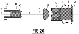
- the release tool 19 comprises an inner rod, provided with a head 34 for holding one end of the implant 10, and a stent 32 slidably mounted coaxially on the rod.
- the release tool 19 further includes an inner sheath 36, slidably mounted relative to the guard 32, an intermediate sheath 24 slidably mounted around the inner sheath 36, and an outer sheath 38 slidably mounted around the intermediate sheath 24.
- the intermediate sheath 24 is the one surrounding the proximal sleeve 14, as described above with reference to the Figures 2 to 4 .
- the holding means 22 comprise a holding sheath 26, as described previously with reference to figures 13 and 14 the intermediate sheath is formed by this holding sheath.
- the release tool 19 may comprise, instead of an intermediate sheath and an outer sheath, only an outer sheath performing the functions of said intermediate sheath and of said outer sheath.
- the guard 32 and the sheaths 36, 24, 38 are slidably movable, independently of one another, and with respect to the rod.
- Locking members are generally provided between the rod and the guard 32, between the guard 32 and the sheaths 36, 24, 38 to prevent the spontaneous sliding of the guard 32, external sheaths 38, intermediate 24 and internal 36 This makes it possible to proceed in successive steps to the withdrawals of the outer sheath 38, of the intermediate sheath 24, of the inner sheath 36.
- the head 34 defines a housing 40 for receiving the implant 10, in which this implant 10 is maintained in contracted configuration.
- the stent 32 and the inner sheath 36 delimit between them an internal annular space 42, intended to receive the distal sleeve 16 and the distal arms 20.
- the distal sleeve 16 is maintained in a configuration contracted by this inner sheath 36.
- the inner sheath 36 and the intermediate sheath 24 delimit between them an intermediate annular space 44, intended to receive the proximal sleeve 14.
- the proximal sleeve 14 is maintained in configuration contracted by this intermediate sheath 24, as described above.
- each proximal arm 18 is pressed against the outer sheath 38 when it is not covered by the sheath intermediate 24, and that the proximal sleeve 14 is in contracted configuration, as shown in FIG. figure 3 .
- the implant 10 When the implant 10 is to be positioned, in particular as a replacement for a native valve, it is introduced between the leaflets 13 of the native valve around the seat of the valve. This introduction can be made using the device of the figure 14 , passing through the left ventricle, as will be described below with reference to Figures 15 to 20 .
- the head 34 and the downstream portion of the tool 19 are introduced into the atrial cavity, beyond the mitral annulus, so that the distal arms 20 are disposed in the atrial cavity beyond the mitral annulus .
- the outer sheath 38 is retracted axially away from the head 34 relative to the intermediate sheath 24, the inner sheath 36 and relative to the guard 32, to discover the distal arms 20, which then deploy.
- the tool 19 is then moved to the left ventricle to press the distal arms 20 against the atrial side of the leaflets 13.
- the outer sheath 38 is further retracted axially to reveal the proximal arms 18. These, which were held pressed against this outer sheath 38, are then deployed under the effect of the constraint imposed by the holding means 22. Indeed, the proximal sleeve 14 is maintained in its contracted configuration, and the proximal arms 18 are not subject to any external stress, so that they are then constrained in their spacing position by the holding means 22, as previously described. .
- the spacing of the proximal arms 18 is then optimally ensured so that the sheets 13 are opposite a reception space 23 defined between these proximal arms 18.
- proximal sleeve 14 and the surrounding sheath 24 surrounding it are thus inserted into the receiving space 23 defined between the proximal arms 18.
- proximal arms 18 extend beyond the distal end 14B of the proximal sleeve 14, this proximal sleeve 14 does not interfere with the insertion of the leaflets 13 into this receiving space 23.
- the inner sheath 36 is retracted to release the distal sleeve 16, as shown in FIG. figure 18 .
- This distal sleeve 16 being disposed inside the proximal sleeve 14, it is maintained in configuration contracted by this proximal sleeve 14, itself maintained in a configuration contracted by the intermediate sheath 24.
- the distal sleeve 16 binds to this proximal sleeve 14.
- proximal sleeves 14 and distal 16 retracts the intermediate sheath 24, so as to release the proximal sleeve 14, as shown in FIG. figure 19 .
- the proximal sleeve 14 then extends radially to its deployed configuration, as well as the distal sleeve 16 within this expanded proximal sleeve 14.
- the holding means 22 release the proximal arms 18, which are then resiliently returned to their anchoring position, as previously described.
- the distal sleeve 16 extends longitudinally, partly inside the proximal sleeve 14, coaxially with this proximal sleeve 14, partly inside the receiving space 23, so that the tissue is received between the proximal arms 18 and the distal sleeve 16, and partly beyond the receiving space 23.
- This deployed configuration corresponds to that of the figure 1 .
- proximal sleeve 14 is arranged axially away from the sheets 13, inside the ventricular cavity.
- the invention can be applied to different proximal arm forms 18
- Said distal portion may also have a domed shape.
- the proximal portion and the bifurcation portion together define a deeper box for the leaflets 13.
- the length of the proximal portion may be chosen more or less important, depending on the desired depth of the box.
- At least one proximal arm 18 has a distal region projecting radially away from the central axis X with respect to an intermediate region of this proximal arm.
- At least one first proximal arm 18 has a first distal region applied opposite a first distal arm 20, and a second proximal arm 18 has a second distal region applied opposite a second distal arm 20, radial extent of the first distal region being greater than the radial extent of the second distal region.
- each proximal arm 18 may be greater or lesser, particularly depending on the predetermined shape of the blood circulation passageway for receiving the implant.
- each proximal arm 18 comprises an elastically deformable intermediate portion in a longitudinal direction of the proximal arm 18.
- the intermediate portion is generally in the form of a spring.
- each proximal arm 18 can vary, and adapt according to the positioning of the proximal sleeve 14 relative to the distal sleeve 16, in particular to ensure optimal pinching of the leaflets 13 between the proximal arms 18 and the distal arms 20.
- each proximal arm 16 has an intermediate portion folded so as to form an axial return defining a cavity. This cavity is intended to form a box for the leaflets 13.
- proximal arms compatible with holding means 22.
- the implant 10 may be installed according to another method of introduction than that described above.
- the different steps of installation of the proximal 14 and distal sleeves 16 may be performed in another order than that described above.
- proximal arms 18 may be previously deployed, the outer sheath 38 being axially retracted to expose these proximal arms 18.
- the proximal sleeve 14 is maintained in its contracted configuration, and the proximal arms 18, which are not subjected to any external stress, are then constrained in their spacing position by the holding means 22, as described above.
- proximal arms 18 The spacing of the proximal arms 18 is then optimally ensured so that the sheets 13 are opposite a reception space 23 defined between these proximal arms 18. It should be noted that starting with the installation of the proximal arms 18, their handling is not hindered by the distal sleeve 16 and the elements for its installation.
- proximal sleeve 14 as well as the surrounding sheath 24 surrounding it, are then moved in the direction of the leaflets 13. These leaflets 13 are thus inserted into the receiving space 23 defined between the proximal arms 18.
- the head 34 and the downstream portion of the tool 19 are then introduced into the atrial cavity, beyond the mitral annulus, so that the distal arms 20 are disposed in the cavity. atrial beyond the mitral ring. In this case, the distal arms 20 are held in the contracted position by the inner sheath 36.
- the inner sheath 36 is then retracted axially away from the head 34 relative to the intermediate sheath 24, and relative to the guard 32, to discover the distal arms 20, which then deploy.
- the tool 19 is then moved to the left ventricle to press the distal arms 20 against the atrial side of the leaflets 13.
- the inner sheath 36 is retracted to release this distal sleeve 16.
- This distal sleeve 16 being disposed inside the proximal sleeve 14, it is maintained in a configuration contracted by this proximal sleeve 14 , itself maintained in configuration contracted by the intermediate sheath 24.
- the distal sleeve 16 binds to this proximal sleeve 14.
- proximal sleeves 14 and distal 16 retracts the intermediate sheath 24, so as to release the proximal sleeve 14.
- the proximal sleeve 14 extends radially to its deployed configuration, and the distal sleeve 16 to the inside of this proximal sleeve 14 deployed.
- the holding means 22 release the proximal arms 18, which are then resiliently returned to their anchoring position, as previously described.
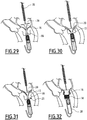
- the delivery method comprises introducing a distal end of the delivery tool 19, including the implant 10 into the contracted configuration, into the cavity ventricular. Then, as shown on the figure 21 the outer sheath 38 is axially retracted to release the proximal arms 18, as previously described. The deployment of the proximal arms 18 defines a reception space 23, which is then completely free.
- proximal arms 18 are deployed before the armature 12 is formed, i.e., before the proximal sleeve 14 is assembled with the distal sleeve 16.
- the inner sheath 36, containing the distal sleeve 16 is moved axially to the atrial cavity, through the mitral annulus, so that the distal arms 20 are positioned in the atrial cavity.
- the inner sheath 36 is retracted axially so as to release the distal arms 20, which are then deployed. During this step, the atrial sleeve 16 remains partially contracted in the inner sheath 36.
- the tool 19 is then moved to the left ventricle to apply the distal arms 20 against the atrial side of the leaflets 13.
- the distal arms 20 apply an axial force against the atrial face of the leaflets 13, this axial force being oriented from the atrial cavity to the ventricular cavity.
- reception space 23 is positioned opposite the sheets 13, so that these sheets 13 are inserted into this reception space 23 when the tool 19 is moved towards these sheets 13, as shown in FIG. figure 25 .
- the proximal arms 18 are applied against the ventricular surface of the leaflets 13.
- the proximal arms 18 apply an axial force against the ventricular face of the leaflets 13, this axial force being oriented from the ventricular cavity to the atrial cavity.
- the direction of the axial force applied by the proximal arms 18 is therefore opposite to the direction of the axial force applied by the distal arms 20.
- the proximal sleeve 14 is axially movable relative to the distal sleeve 16, so that the relative position of the proximal sleeve 14 with respect to the distal sleeve 16 can be selected according to the configuration of the blood circulation passage in which the implant is installed.
- the position of the proximal sleeve 14 is adjusted, then the inner sheath 36 and the outer sheath 38 are retracted, so that the distal sleeve 16 and the proximal sleeve 14 are deployed, as shown in FIG. figure 26 . It should be noted that the distal sleeve 16 and the proximal sleeve 14 can be deployed simultaneously, or alternatively the distal sleeve 16 is deployed inside the proximal sleeve 14 prior to the deployment of this proximal sleeve 14.
- armature 12 is formed only in the deployed configuration.
- the drop tool is removed from the patient.
- proximal sleeve 14 and the distal sleeve 16 forming two separate sets, it is possible to bring them into the blood circulation passage via two separate access routes.
- the distal sleeve 16 can be passed anterograde transvenous, and thus introduced into the atrial cavity without passing through the ventricular cavity, and the proximal sleeve 14 can be brought transaortically retrograde way, and thus introduced into the ventricular cavity without go through the atrial cavity.
- the treatment device comprises a first release tool for the proximal sleeve 14 and a second release tool for the distal sleeve 16.
- first and second drop tools have diameters smaller than the diameter of a release tool carrying both the proximal sleeve 14 and distal 16.
- this method of installation there are two ways of access narrower than the only access path required for the previously described installation methods.
- a first part 19A of the delivery tool comprising an outer sheath 38 and the proximal sleeve 14 in a configuration contracted inside this outer sheath 38, are introduced into the ventricular cavity by a first path.
- a second portion 19B of the delivery tool comprising an inner sheath 36 and the distal sleeve 16 in a configuration contracted within this inner sheath 36, are introduced into the atrial cavity by a second path different from said first pathway.
- the second portion 19B of the delivery tool is not inserted through the mitral annulus into the atrial cavity.
- the outer sheath 38 is then axially retracted so as to release the proximal arms 18, which are thus deployed as previously described.
- the deployment of the proximal arms 18 thus defines the reception space 23.
- the inner sheath 36 containing the distal sleeve 16 is moved axially to the ventricular cavity, beyond the mitral annulus, so that the distal arms 20 remain positioned in the atrial cavity, and that the distal sleeve 16 is positioned partially in the ventricular cavity.
- the inner sheath 36 is retracted axially to release the distal arms 20, which then deploy.
- the distal sleeve 16 remains partially contracted, for example by virtue of an annular holding element 66 surrounding this distal sleeve 16.
- the distal arms 20 are then applied against the atrial side of the leaflets 13, as shown in FIG. figure 30 .
- the distal arms 20 apply an axial force against the atrial side of the leaflets 13, this axial force being oriented from the atrial cavity to the ventricular cavity.
- the receiving space 23 is then positioned facing the sheets 13, so that they are inserted into this receiving space 23 when the first portion 14A of the release tool is moved to these sheets 13, as shown on the figure 31 . Then, the reception space 23 is positioned opposite the sheets 13, so that these sheets 13 are inserted into this reception space 23 when the tool 19 is moved towards these sheets 13, as shown in FIG. figure 25 .
- the proximal arms 18 are applied against the ventricular surface of the leaflets 13.
- the proximal arms 18 apply an axial force against the ventricular face of the leaflets 13, this axial force being oriented from the ventricular cavity to the atrial cavity.
- the direction of the axial force applied by the proximal arms 18 is therefore opposite to the direction of the axial force applied by the distal arms 20.
- the proximal sleeve 14 is axially movable relative to the distal sleeve 16, so that the relative position of the proximal sleeve 14 with respect to the distal sleeve 16 can be selected according to the configuration of the blood circulation passage in which the implant is installed.
- the position of the proximal sleeve 14 is adjusted, then the annular holding member 66 and the outer sheath 38 are retracted, so that the distal sleeve 16 and the proximal sleeve 14 are deployed, as shown in FIG. figure 32 .
- distal sleeve 16 and the proximal sleeve 14 can be deployed simultaneously, or alternatively the distal sleeve 16 is deployed inside the proximal sleeve 14 prior to the deployment of this proximal sleeve 14.
- armature 12 is formed only in the deployed configuration.
- the release tool is removed from the patient, each of its parts through the corresponding path.
Description
La présente invention concerne un implant perfectionné destiné à être placé dans un passage de circulation de sang, notamment dans une valve auriculo-ventriculaire cardiaque.The present invention relates to an improved implant for placement in a blood circulation passage, particularly in a cardiac atrioventricular valve.
Un tel implant est notamment destiné au remplacement d'une valve cardiaque native, en particulier d'une valve mitrale ou d'une valve tricuspide.Such an implant is particularly intended for the replacement of a native heart valve, in particular a mitral valve or a tricuspid valve.
Dans ce cas d'une valve mitrale, l'implant est destiné à être placé dans un passage sanguin d'une valve auriculo-ventriculaire d'un coeur humain ou animal.In this case of a mitral valve, the implant is intended to be placed in a blood passage of an atrioventricular valve of a human or animal heart.
Lors de la systole, le passage sanguin entre l'oreillette gauche et le ventricule gauche du coeur est interrompu par la fermeture d'une valve cardiaque native présente dans un appareil mitral. Cette valve assure une circulation univoque du flux sanguin, évitant un reflux à l'issue de la contraction ventriculaire.During systole, the passage of blood between the left atrium and the left ventricle of the heart is interrupted by the closure of a native heart valve present in a mitral apparatus. This valve ensures unambiguous circulation of the blood stream, avoiding reflux at the end of the ventricular contraction.
L'appareil mitral comprend un anneau mitral, deux feuillets valvulaires reliés à cet anneau, et un appareil sous-valvulaire comprenant des cordages et des piliers. Les feuillets valvulaires comportent un feuillet antérieur, également appelé « grande valve mitrale », et un feuillet postérieur, également appelé « petite valve mitrale ».The mitral apparatus includes a mitral ring, two valvular leaflets attached to this ring, and a subvalvular apparatus including ropes and pillars. The valvular leaflets include an anterior leaflet, also called a "large mitral valve," and a posterior leaflet, also called a "small mitral valve."
La partie de liaison de l'anneau avec la grande valve mitrale est fibreuse, alors que la partie de liaison de l'anneau avec la petite valve mitrale est musculaire. Les petite et grande valves mitrales sont reliées à la partie ventriculaire par des cordages, eux-mêmes reliés aux piliers. En diastole, les deux feuillets s'ouvrent pour libérer le passage entre l'oreillette et le ventricule gauche.The connecting part of the ring with the large mitral valve is fibrous, while the connecting part of the ring with the small mitral valve is muscular. The small and large mitral valves are connected to the ventricular part by ropes, themselves connected to the pillars. In diastole, the two leaflets open to free the passage between the atrium and the left ventricle.
En systole, la contraction ventriculaire engendre une brusque élévation de la pression intra-ventriculaire gauche, provoquant l'éjection du sang à travers la valve aortique. Simultanément, la contraction des piliers et la mise en tension des cordages provoquent la jonction des feuillets entre eux, de façon à isoler de manière étanche les cavités atriale et ventriculaire gauches.In systole, ventricular contraction causes a sudden rise in left ventricular pressure, causing ejection of blood through the aortic valve. Simultaneously, the contraction of the pillars and the tensioning of the ropes cause the sheets to join together, so as to seal the left atrial and ventricular cavities in a sealed manner.
Toutefois, des maladies affectent les valves et les cordages. En particulier, celles-ci peuvent souffrir d'une dégénérescence autorisant ainsi un reflux ou une régurgitation.However, diseases affect valves and ropes. In particular, they can suffer from degeneration thus allowing reflux or regurgitation.
De plus, en cas de régurgitation mitrale sévère et chronique, le ventricule gauche sous-jacent se dilate et sa contractivité diminue, ce qui peut conduire à la nécessité d'une intervention chirurgicale cardiaque, même en l'absence de tout symptôme.In addition, in cases of severe and chronic mitral regurgitation, the underlying left ventricle expands and its contractivity decreases, which may lead to the need for cardiac surgery, even in the absence of any symptoms.
Afin de remédier à ces problèmes, il est connu d'implanter un implant entre les feuillets délimitant la valve malade. L'implant comporte par exemple une endoprothèse tubulaire déployable et un obturateur souple réalisé dans un tissu d'origine animal. L'obturateur souple est fixé à demeure dans l'endoprothèse.In order to remedy these problems, it is known to implant an implant between the sheets delimiting the sick valve. The implant comprises for example a deployable tubular stent and a flexible obturator made of a tissue of animal origin. The flexible obturator is fixed permanently in the stent.
De tels implants sont généralement implantables de manière moins invasive qu'un remplacement valvulaire chirurgical, ce qui limite les risques associés à l'implantation de la valve, notamment en termes de mortalité.Such implants are generally less invasively implantable than a surgical valve replacement, which limits the risks associated with the implantation of the valve, especially in terms of mortality.
On connaît par exemple, d'après
Un tel implant comporte une pluralité de bras atriaux (également appelés « bras distaux »), et une pluralité de bras ventriculaires (également appelés « bras proximaux ») disposés en regard des bras atriaux pour pincer l'anneau mitral, en prenant appui sur la face atriale des feuillets de la valve native en la plicaturant. Les bras ventriculaires sont formés par des crochets disposés à l'extrémité ventriculaire de l'armature et repliés vers l'extrémité atriale. Les bras atriaux sont formés par des boucles en forme de V s'étendant en regard des bras ventriculaires, au voisinage de ceux-ci, mais s'écartant de l'armature et des bras atriaux.Such an implant has a plurality of atrial arms (also referred to as "distal arms"), and a plurality of ventricular arms (also referred to as "proximal arms") disposed opposite the atrial arms to pinch the mitral annulus, resting on the atrial side of the leaflets of the native valve by plication. The ventricular arms are formed by hooks arranged at the ventricular end of the frame and bent towards the atrial end. The atrial arms are formed by V-shaped loops extending opposite the ventricular arms, in the vicinity thereof, but deviating from the armature and the atrial arms.
Les extrémités des bras ventriculaires et des bras atriaux sont disposées à l'écart l'une de l'autre et sont enfoncées respectivement dans une face atriale et dans une face ventriculaire de l'anneau mitral.The ends of the ventricular arms and the atrial arms are disposed apart from each other and are respectively seated in an atrial and a ventricular face of the mitral annulus.
Un autre exemple d'implant est notamment décrit dans
On notera que l'installation d'un implant mitral en remplacement de la valve native peut être réalisée en passant par la cavité atriale, ou en passant en variante par la cavité ventriculaire. Cette installation est généralement réalisée au moyen d'un outil de largage adapté. La structure de cet outil de largage peut être différente en fonction du côté (atrial ou ventriculaire) par lequel on passe pour réaliser cette installation.Note that the installation of a mitral implant to replace the native valve can be performed through the atrial cavity, or alternatively through the ventricular cavity. This installation is generally performed by means of a suitable drop tool. The structure of this delivery tool may be different depending on the side (atrial or ventricular) through which one goes to achieve this installation.
L'invention a notamment pour but de faciliter l'installation d'un implant mitral, notamment lorsque celui-ci est installé en passant par la cavité ventriculaire.The invention particularly aims to facilitate the installation of a mitral implant, especially when it is installed through the ventricular cavity.
A cet effet, l'invention a notamment pour objet un implant destiné à être placé dans un passage de circulation de sang, et à être fixé sur un tissu, et comprenant :
- un manchon proximal, de forme générale tubulaire autour d'un axe central, s'étendant longitudinalement entre une extrémité proximale et une extrémité distale, le manchon proximal étant déployable entre une configuration contractée et une configuration déployée,
- une pluralité de bras proximaux, s'étendant chacun entre une première extrémité liée à l'extrémité distale du manchon proximal, et une seconde extrémité libre destinée à s'appuyer sur une première face du tissu, chaque bras proximal s'étendant dans la direction de l'axe central de sorte que son extrémité libre soit disposée au-delà de l'extrémité distale du manchon proximal,
- un manchon distal, de forme générale tubulaire autour de l'axe central, déployable entre une configuration contractée et une configuration déployée, destiné à être assemblé avec le manchon proximal pour former ensemble une armature tubulaire, cette armature définissant un conduit interne de circulation du sang lorsque le manchon proximal et le manchon distal sont assemblés et chacun en configuration déployée,
- une pluralité de bras distaux, portés par le manchon distal, et s'étendant sensiblement perpendiculairement à l'axe central dans la configuration déployée, destinés à s'appuyer sur une deuxième face du tissu, de sorte que le tissu soit alors pincé entre les bras proximaux et les bras distaux,
- au moins un bras proximal est déformable élastiquement, entre une position d'écartement et une position d'ancrage, telles que, en l'absence de sollicitation extérieure, la distance radiale entre son extrémité libre et son extrémité liée est supérieure dans la position d'écartement plutôt que dans la position d'ancrage, ce bras proximal étant rappelé élastiquement vers sa position d'ancrage,
- l'implant comporte des moyens de maintien dudit au moins un bras proximal déformable dans sa position d'écartement, comprenant :
- une première butée, portée par ce bras proximal, et
- une seconde butée, destinée à coopérer avec la première butée lorsque le manchon proximal est en configuration contractée pour maintenir ce bras proximal dans sa position d'écartement, et à libérer cette première butée lorsque le manchon proximal est en configuration déployée pour laisser le bras proximal se déplacer vers sa position d'ancrage.
- a proximal sleeve, generally tubular in shape about a central axis, extending longitudinally between a proximal end and a distal end, the proximal sleeve being deployable between a contracted configuration and an expanded configuration,
- a plurality of proximal arms, each extending between a first end connected to the distal end of the proximal sleeve, and a second free end for pressing on a first face of the tissue, each proximal arm extending in the direction of the central axis so that its free end is disposed beyond the distal end of the proximal sleeve,
- a distal sleeve, generally tubular in shape about the central axis, deployable between a contracted configuration and an expanded configuration, to be assembled with the proximal sleeve to form a tubular frame together, said frame defining an internal blood circulation conduit when the proximal sleeve and the distal sleeve are assembled and each in deployed configuration,
- a plurality of distal arms, carried by the distal sleeve, and extending substantially perpendicular to the central axis in the deployed configuration, for resting on a second face of the tissue, so that the tissue is then pinched between the proximal arms and distal arms,
- at least one proximal arm is elastically deformable, between a spacing position and an anchoring position, such that, in the absence of external stress, the radial distance between its free end and its bonded end is greater in the position d spacing rather than in the anchoring position, this proximal arm being resiliently biased towards its anchoring position,
- the implant comprises means for maintaining said at least one deformable proximal arm in its position of separation, comprising:
- a first stop carried by this proximal arm, and
- a second stop, intended to cooperate with the first stop when the proximal sleeve is in contracted configuration to maintain the proximal arm in its position of separation, and to release this first stop when the proximal sleeve is in deployed configuration to allow the proximal arm move to its anchor position.
Chaque bras proximal s'étend depuis l'extrémité distale du manchon proximal au-delà de cette extrémité distale. Ainsi, lorsque le manchon proximal est approché des feuillets valvulaires depuis la cavité ventriculaire, les bras proximaux se trouvent en avant de ce manchon proximal, si bien qu'ils peuvent accueillir les feuillets valvulaires sans être gênés par ce manchon proximal.Each proximal arm extends from the distal end of the proximal sleeve beyond this distal end. Thus, when the proximal sleeve is approached valvular leaflets from the ventricular cavity, the proximal arms are in front of this proximal sleeve, so that they can accommodate the valve leaflets without being hampered by this proximal sleeve.
Ainsi, la structure de l'implant défini ci-dessus permet une grande facilité d'insertion des feuillets valvulaires dans un espace de réception délimité par les bras proximaux.Thus, the structure of the implant defined above allows a great ease of insertion of valve leaflets in a reception space delimited by the proximal arms.
En outre, grâce aux moyens de maintien, l'écartement des bras proximaux est assuré et optimisé lors de l'installation de l'implant.In addition, thanks to the holding means, the spacing of the proximal arms is ensured and optimized during the installation of the implant.
Il convient de noter que le manchon proximal et le manchon distal forment ensemble un corps d'implant lorsqu'ils sont assemblés. Ainsi, le corps d'implant n'est considéré comme constitué uniquement lorsque ces manchons proximal et distal sont assemblés.It should be noted that the proximal sleeve and the distal sleeve together form an implant body when assembled. Thus, the implant body is considered to be constituted only when these proximal and distal sleeves are assembled.
Un implant selon l'invention peut comporter en outre l'une ou plusieurs des caractéristiques suivantes, prises isolément ou suivant toutes combinaisons techniquement envisageables.
- La première butée du bras proximal s'étend latéralement par rapport à ce bras proximal, cette première butée étant de préférence agencée à proximité de l'extrémité liée de ce bras proximal.
- La seconde butée est portée par le manchon proximal.
- Le manchon proximal est formé d'éléments filiformes disposés en grillage, formant des mailles, par exemple en losange, chaque bras proximal muni d'une première butée étant agencé circonférentiellement sur le manchon proximal entre deux mailles consécutives, la seconde butée correspondante étant portée par au moins l'un des éléments filiformes formant ces deux mailles consécutives, ces éléments filiformes étant rapprochés l'un de l'autre en configuration contractée, de sorte que la seconde butée coopère avec la première butée, et éloignés l'un de l'autre en configuration déployée, de façon à laisser un passage radial pour la première butée, libérant ainsi cette première butée.
- Le manchon proximal porte au moins deux bras proximaux munis chacun d'une première butée, tels que la distance entre la première butée et l'extrémité liée de l'un de ces deux bras proximaux est supérieure à la distance entre la première butée et l'extrémité liée de l'autre de ces deux bras proximaux.
- La première butée d'au moins l'un des bras proximaux est formée par une partie en saillie de ce bras proximal, s'étendant latéralement par rapport à ce bras proximal.
- La première butée d'au moins l'un des bras proximaux est formée par un élément rapporté sur ce bras proximal, par exemple soudé, cet élément s'étendant latéralement par rapport à ce bras proximal.
- The first abutment of the proximal arm extends laterally with respect to this proximal arm, this first abutment preferably being arranged close to the end of this proximal arm.
- The second stop is carried by the proximal sleeve.
- The proximal sleeve is formed of filiform elements arranged in mesh, forming meshes, for example diamond-shaped, each proximal arm provided with a first stop being arranged circumferentially on the proximal sleeve between two consecutive meshes, the corresponding second stop being carried by at least one of the filiform elements forming these two consecutive meshes, these filiform elements being brought closer to one another in the contracted configuration, so that the second stop cooperates with the first stop, and away one from the another deployed configuration, so as to leave a radial passage for the first stop, thus releasing this first stop.
- The proximal sleeve carries at least two proximal arms each provided with a first stop, such that the distance between the first stop and the connected end of one of these two proximal arms is greater than the distance between the first stop and the first stop. linked end of the other of these two proximal arms.
- The first abutment of at least one of the proximal arms is formed by a protruding portion of the proximal arm extending laterally of the proximal arm.
- The first abutment of at least one of the proximal arms is formed by an element attached to this proximal arm, for example welded, this element extending laterally with respect to this proximal arm.
L'invention concerne également un dispositif de traitement d'un passage de circulation de sang, notamment dans une valve auriculo-ventriculaire cardiaque, caractérisé en ce qu'il comporte un implant tel que défini précédemment, et un outil de largage de cet implant, les manchons proximal et distal étant montés dans leurs configurations contractées dans cet outil de largage.The invention also relates to a device for treating a blood flow passage, in particular in a cardiac atrioventricular valve, characterized in that it comprises an implant as defined above, and a delivery tool for this implant, the proximal and distal sleeves being mounted in their configurations contracted in this release tool.
Un dispositif de traitement selon l'invention peut comporter en outre l'une ou plusieurs des caractéristiques suivantes, prises seules ou en combinaison :
- L'outil de largage comporte une gaine de maintien de chaque bras proximal muni d'une première butée dans sa positions d'écartement, ladite gaine de maintien présente une forme générale de révolution autour de l'axe longitudinal, et est destinée à être disposée autour du manchon proximal en configuration contractée, ladite gaine de maintien comporte des bandes longitudinales séparées par des ouvertures longitudinales, chaque bande longitudinale étant destinée à passer à travers une ouverture prévue dans un bras proximal respectif, et chaque bande longitudinale comporte une seconde butée destinée à coopérer avec la première butée du bras proximal à travers lequel passe cette bande longitudinale.
- Ladite bande longitudinale est munie d'un bossage, faisant saillie radialement vers l'extérieur de la gaine de maintien, portant ladite seconde butée.
- The delivery tool comprises a holding sheath of each proximal arm provided with a first stop in its spacing positions, said holding sheath having a general shape of revolution about the longitudinal axis, and is intended to be arranged around the proximal sleeve in contracted configuration, said holding sheath comprises longitudinal strips separated by longitudinal openings, each longitudinal strip being intended to pass through a aperture provided in a respective proximal arm, and each longitudinal band has a second stop for cooperating with the first stop of the proximal arm through which this longitudinal band passes.
- Said longitudinal strip is provided with a boss, projecting radially outwardly of the holding sheath, bearing said second stop.
L'invention concerne également un procédé d'installation d'un implant tel que défini précédemment, sur les feuilles d'une valve native, entre une cavité atriale et une cavité ventriculaire d'un coeur, les feuillets présentant une face atriale et une face ventriculaire, le procédé comportant :
- une étape de positionnement des bras distaux dans la cavité atriale,
- une étape de déploiement des bras distaux dans la cavité atriale,
- une étape d'application des bras distaux contre la face atriale des feuillets,
- une étape de déplacement du manchon proximal vers les feuillets, avec les bras proximaux déployés de manière à définir un espace de réception des feuillets, afin d'insérer les feuillets dans cet espace de réception, et d'application des bras proximaux contre la face ventriculaire des feuillets en appliquant une force axiale vers ces feuillets,
- une étape de déploiement du manchon distal et du manchon proximal, et d'assemblage du manchon distal avec le manchon proximal de manière à former une armature tubulaire de l'implant.
- a step of positioning the distal arms in the atrial cavity,
- a step of deployment of the distal arms in the atrial cavity,
- a step of applying the distal arms against the atrial side of the leaflets,
- a step of moving the proximal sleeve towards the leaflets, with the proximal arms deployed so as to define a space for receiving the leaflets, in order to insert the leaflets in this receiving space, and for applying the proximal arms against the ventricular surface slips by applying an axial force to these slips,
- a step of deploying the distal sleeve and the proximal sleeve, and assembling the distal sleeve with the proximal sleeve so as to form a tubular armature of the implant.
Avantageusement, le procédé utilise un outil de largage dans lequel l'implant est logé en position contractée, l'outil comportant :
- une gaine intérieure pour retenir le manchon distal en configuration contractée, et retenir les bras distaux en position axiale,
- une gaine extérieure pour retenir le manchon proximal en configuration contractée.
- an inner sheath for retaining the distal sleeve in contracted configuration, and retaining the distal arms in axial position,
- an outer sheath for retaining the proximal sleeve in contracted configuration.
Dans ce cas, le procédé comporte :
- une étape de déploiement des bras proximaux, notamment en rétractant la gaine extérieure de manière à libérer les bras proximaux,
- une étape de positionnement des bras distaux dans la cavité atriale, alors que la gaine intérieure est toujours positionnée autour des bras distaux,
- une étape de déploiement des bras distaux dans la cavité atriale, en rétractant la gaine intérieure de manière à libérer ces bras distaux,
- une étape d'application des bras distaux contre la face atriale des feuillets, en déplaçant l'outil vers la cavité ventriculaire de manière à appliquer un effort axial vers cette cavité ventriculaire,
- une étape de déplacement du manchon proximal vers les feuillets, alors que la gaine extérieure recouvre le manchon proximal, et d'application des bras proximaux contre la face ventriculaire des feuillets pour appliquer un effort axial orienté vers la cavité atriale,
- une étape de déploiement des manchons proximal et distal, en rétractant les gaines intérieure et extérieure.
- a step of deployment of the proximal arms, in particular by retracting the outer sheath so as to release the proximal arms,
- a step of positioning the distal arms in the atrial cavity, while the inner sheath is still positioned around the distal arms,
- a step of deploying the distal arms in the atrial cavity, by retracting the inner sheath so as to release these distal arms,
- a step of applying the distal arms against the atrial aspect of the leaflets, by moving the tool towards the ventricular cavity so as to apply an axial force towards this ventricular cavity,
- a step of moving the proximal sleeve towards the leaflets, while the outer sheath covers the proximal sleeve, and applying the proximal arms against the ventricular side of the leaflets to apply an axial force directed towards the atrial cavity,
- a step of deployment of the proximal and distal sleeves, retracting the inner and outer sheaths.
Conformément à un mode de réalisation avantageux:
- l'étape de positionnement des bras distaux dans la cavité atriale fait suite à l'étape de déploiement des bras proximaux,
- l'étape de déploiement des bras distaux dans la cavité atriale fait suite à l'étape de positionnement des bras distaux dans la cavité atriale,
- l'étape d'application des bras distaux contre la face atriale des feuillets fait suite à l'étape de déploiement des bras distaux dans la cavité atriale,
- l'étape de déplacement du manchon proximal vers les feuillets fait suite à l'étape d'application des bras distaux contre la face atriale des feuillets,
- l'étape de déploiement des manchons proximal et distal fait suite à l'étape de déplacement du manchon proximal vers les feuillets.
- the step of positioning the distal arms in the atrial cavity follows the step of deployment of the proximal arms,
- the step of deploying the distal arms in the atrial cavity follows the step of positioning the distal arms in the atrial cavity,
- the step of applying the distal arms against the atrial side of the leaflets follows the step of deploying the distal arms in the atrial cavity,
- the step of moving the proximal sleeve towards the leaflets follows the step of applying the distal arms against the atrial side of the leaflets,
- the step of deployment of the proximal and distal sleeves follows the step of moving the proximal sleeve to the leaflets.
Conformément à un autre mode de réalisation :
- la gaine extérieure et le manchon proximal en configuration contractée dans la gaine extérieure sont introduits dans la cavité ventriculaire par une première voie, et
- la gaine intérieure et le manchon distal en configuration contractée dans la gaine intérieure sont introduits dans la cavité atriale par une seconde voie différente de la première.
- the outer sheath and the proximal sleeve in contracted configuration in the outer sheath are introduced into the ventricular cavity by a first path, and
- the inner sheath and the distal sleeve in contracted configuration in the inner sheath are introduced into the atrial cavity by a second path different from the first.
La valve native est choisie entre une valve mitrale ou une valve tricuspide.The native valve is selected from a mitral valve or a tricuspid valve.
L'invention sera mieux comprise à la lecture de la description qui va suivre, donnée uniquement à titre d'exemple, et faite en se référant aux figures annexées, parmi lesquelles :
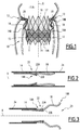
- la
figure 1 est une vue schématique de profil d'un implant selon un exemple de mode de réalisation de l'invention, disposé dans un passage de circulation du sang, dans une valve auriculo-ventriculaire cardiaque ; - la
figure 2 est une vue schématique de profil d'un manchon proximal de l'implant de lafigure 1 , lorsque ce manchon proximal est disposé dans une gaine d'un outil de largage de l'implant ; - la
figure 3 est une vue schématique de profil du manchon de lafigure 2 , en configuration contractée, dont les bras proximaux sont en position d'écartement ; - la
figure 4 est une vue schématique de profil du manchon proximal desfigures 2 et 3 , en configuration déployée ; - la
figure 5 représente un détail du manchon proximal desfigures 2 à 4 , montrant des moyens de maintien, selon un premier exemple de mode de réalisation, d'un bras proximal dans sa position d'écartement, ces moyens de maintien étant vus de face ; - la
figure 6 est une vue similaire à lafigure 5 , représentant les moyens de maintien lorsque le manchon proximal est en configuration déployée, et les bras proximaux en position d'ancrage ; - les
figures 7 et 8 sont des vues similaires auxfigures 5 et 6 , représentant des moyens de maintien, selon un deuxième exemple de mode de réalisation, respectivement lorsque le manchon proximal est en configuration contractée et déployée ; - les
figures 9 et 10 sont des vues similaires auxfigures 7 et 8 , de moyens de maintien selon un troisième exemple de mode de réalisation, respectivement lorsque le manchon proximal est en configuration contractée et déployée ; - la
figure 11 représente un manchon proximal, représenté déroulé, comprenant des moyens de maintien selon un quatrième exemple de mode de réalisation de l'invention ; - la
figure 12 est une vue schématique en perspective d'un manchon proximal comportant des moyens de maintien selon un cinquième exemple de mode de réalisation de l'invention ; - la
figure 13 est une vue en perspective d'une gaine de maintien des moyens de maintien de lafigure 12 ; - les
figures 14 à 20 représentent schématiquement, en coupe axiale, un dispositif de traitement selon l'invention, représenté dans différentes phases de largage de l'implant ; - les
figures 21 à 26 représentent schématiquement, en coupe axiale, un dispositif de traitement selon l'invention, représenté dans différentes phases de largage de l'implant selon un second mode de réalisation du largage ; - les
figures 27 à 32 représentent schématiquement, en coupe axiale, un dispositif de traitement selon l'invention, représenté dans différentes phases de largage de l'implant selon un troisième mode de réalisation du largage.
- the
figure 1 is a schematic side view of an implant according to an exemplary embodiment of the invention, disposed in a passage of blood circulation, in a cardiac atrioventricular valve; - the
figure 2 is a schematic profile view of a proximal sleeve of the implant of thefigure 1 when this proximal sleeve is disposed in a sheath of an implant release tool; - the
figure 3 is a schematic profile view of the sleeve of thefigure 2 , in contracted configuration, whose proximal arms are in spaced position; - the
figure 4 is a schematic profile view of the proximal sleeve ofFigures 2 and 3 , in deployed configuration; - the
figure 5 represents a detail of the proximal sleeve ofFigures 2 to 4 , showing holding means, according to a first exemplary embodiment, of a proximal arm in its position of separation, these holding means being seen from the front; - the
figure 6 is a view similar to thefigure 5 , representing the holding means when the proximal sleeve is in the deployed configuration, and the proximal arms in the anchoring position; - the
Figures 7 and 8 are similar views toFigures 5 and 6 , representing holding means, according to a second exemplary embodiment, respectively when the proximal sleeve is in contracted and deployed configuration; - the
Figures 9 and 10 are similar views toFigures 7 and 8 holding means according to a third exemplary embodiment, respectively when the proximal sleeve is in contracted and deployed configuration; - the
figure 11 represents a proximal sleeve, shown unwound, comprising holding means according to a fourth exemplary embodiment of the invention; - the
figure 12 is a schematic perspective view of a proximal sleeve having holding means according to a fifth exemplary embodiment of the invention; - the
figure 13 is a perspective view of a holding sheath of the holding means of thefigure 12 ; - the
Figures 14 to 20 schematically represent, in axial section, a treatment device according to the invention, represented in different phases of release of the implant; - the
Figures 21 to 26 show schematically, in axial section, a treatment device according to the invention, shown in different phases of release of the implant according to a second embodiment of the release; - the
Figures 27 to 32 schematically represent, in axial section, a treatment device according to the invention, shown in different phases of release of the implant according to a third embodiment of the release.
On a représenté, sur la
L'implant 10 est avantageusement une valve cardiaque destinée à remplacer une valve native défectueuse, plus particulièrement une valve auriculo-ventriculaire. Ainsi, l'implant 10 est avantageusement destiné à remplacer une valve mitrale native située entre une oreillette gauche 11A et un ventricule gauche 11B du coeur, de façon à permettre une circulation univoque du flux sanguin entre cette oreillette gauche 11 A et ce ventricule gauche 11 B.The
En variante, l'implant est une valve atrio-ventriculaire, destinée à remplacer la valve cardiaque en position tricuspide. Il convient de noter que, dans ce cas, l'implant peut être apporté via une voie trans-ventriculaire, ou en variante via une voie trans-jugulaire.Alternatively, the implant is an atrio-ventricular valve, intended to replace the heart valve in tricuspid position. It should be noted that in this case, the implant can be delivered via a transventricular pathway, or alternatively via a trans-jugular pathway.
L'implant 10 est notamment destiné à être fixé sur un tissu 13 du coeur, ce tissu 13 étant dans l'exemple représenté formé par des feuillets de valve native.The
L'implant 10 comporte une armature tubulaire 12, destinée à définir un conduit interne de circulation de sang. Cette armature 12 est avantageusement munie d'un obturateur (non représenté) à base de tissu, notamment de tissu synthétique ou naturel, tel que bovin, équin et/ou de péricarde porcin. Cet obturateur est destiné à assurer la circulation univoque du sang à travers cette armature 12.The
L'armature tubulaire 12 comporte un manchon proximal 14 et un manchon distal 16, rapportés l'un sur l'autre et assemblés pour former l'armature 12.The
Il convient de noter que l'armature 12 ne peut être considérée comme formée que lorsque le manchon proximal 14 et le manchon distal 16 sont assemblés.It should be noted that the
Le manchon proximal 14 présente une forme générale tubulaire autour d'un axe central X. Ce manchon proximal 14 s'étend longitudinalement, dans la direction de l'axe central X, entre une extrémité proximale 14A et une extrémité distale 14B. Ce manchon proximal 14 est déployable entre une configuration contractée (qui sera décrite ultérieurement, notamment en référence aux
L'implant 10 comporte par ailleurs une pluralité de bras proximaux 18, s'étendant chacun entre une première extrémité 18A liée à l'extrémité distale 14B du manchon proximal 14, et une seconde extrémité libre 18B destinée à s'appuyer sur une face proximale d'un feuillet 13 de valve. Le manchon proximal 14 forme donc, avec les bras proximaux 18, un premier ensemble d'un seul tenant.The
Chaque bras proximal 18 s'étend dans la direction de l'axe central X de sorte que son extrémité libre 18B soit disposée au-delà de l'extrémité distale 14B du manchon proximal 14.Each
Les bras proximaux 18 étant destinés à s'appuyer sur le feuillet 13 de valve du côté du ventricule gauche, ces bras proximaux 18 sont également appelés «bras ventriculaires ».Since the
Dans l'exemple de la
Conformément à une variante préférée, chaque bras proximal 18 comporte deux branches convergeant distalement l'une vers l'autre pour présenter sensiblement une forme de V retourné en configuration déployée. De tels bras proximaux 18 sont notamment représentés sur la
Avantageusement, deux bras proximaux 18 adjacents présentent une partie commune depuis laquelle s'étendent une branche respective de chacun de ces bras proximaux. Ainsi, chaque bras proximal 18 comporte deux parties de liaison avec le manchon proximal, chacune de ces parties de liaison étant commune à un bras proximal adjacent respectif, comme cela est représenté sur la
Les parties de liaison d'un bras proximal 18 forment son extrémité liée 18A.The connecting portions of a
Avantageusement, les formes des bras proximaux 18 sont adaptées à la configuration prédéterminée du passage de circulation de sang destiné à recevoir l'implant 10. Ainsi, par exemple, au moins un bras proximal 18 présente une longueur supérieure à celle d'au moins un autre bras proximal. En variante ou en combinaison avec ladite longueur supérieure, la distance transversale entre les parties de liaison d'au moins un bras proximal est inférieure à celle entre les parties de liaison d'au moins un autre bras proximal.Advantageously, the shapes of the
Le manchon distal 16 présente également une forme générale tubulaire autour de l'axe central X. Ce manchon distal 16 est également déployable entre une configuration contractée et une configuration déployée. Plus particulièrement, le manchon distal 16 est destiné à être assemblé avec le manchon proximal 14 pour former l'armature tubulaire 12 de l'implant 10 lorsque ce manchon proximal 14 et ce manchon distal 16 sont assemblés, chacun en configuration déployée.The
L'implant 10 comporte par ailleurs une pluralité de bras distaux 20, chacun étant porté par le manchon distal 16, et s'étendant sensiblement perpendiculairement à l'axe central X lorsque ce manchon distal 16 est dans sa configuration déployée. Ainsi, le manchon distal 16 forme, avec les bras distaux 20, un second ensemble d'un seul tenant, destiné à être rapporté sur le premier ensemble.The
Les bras distaux 20 sont destinés à s'appuyer sur une face distale d'un feuillet 13 de valve, c'est-à-dire du côté de l'oreillette gauche, également appelée cavité atriale, lorsque la valve est une valve mitrale. Ainsi, ces bras distaux 20 sont également appelés « bras atriaux ».The
Chaque bras distal 20 forme par exemple une boucle faisant saillie transversalement par rapport à l'axe central X.Each
Lorsque l'implant 10 est installé dans le conduit de circulation de sang, les feuillets 13 de valve sont pincés entre les bras proximaux 18 et les bras distaux 20, assurant ainsi l'ancrage de l'implant 10, comme cela est représenté sur la
On notera que l'implant 10 est dit «en configuration déployée » lorsque le manchon proximal 14 et le manchon distal 16 sont assemblés en configurations déployées. En revanche, l'implant 10 est dit « en configuration contractée » lorsqu'il est disposé dans un outil de largage 19, dans lequel les manchons proximal 14 et distal 16 sont disposés en configurations contractées, comme cela sera décrit ultérieurement, notamment en référence aux
Avantageusement, chacun des manchons proximal 14 et distal 16, donc également l'implant 10, est auto-expansible, c'est-à-dire que sa configuration déployée constitue sa position de repos. Ainsi, chacun des manchons proximal 14 et distal 16, donc également l'implant 10, dans sa configuration contractée, est sollicité élastiquement vers sa configuration déployée.Advantageously, each of the proximal 14 and
Par exemple, le manchon proximal 14, le manchon distal 16, les bras proximaux 18 et les bras distaux 20 sont formés d'un acier inoxydable ayant des propriétés élastiques. En variante, ces éléments sont formés à base de métal à mémoire de forme tel que du nitinol (nickel/titane) ou d'une fibre souple polymère.For example, the
Le manchon proximal 14 est par exemple formé par un treillis d'éléments filiformes 15 entrelacés, délimitant des mailles M, par exemple des mailles polygonales, de préférence des mailles en forme de losange.The
De même, le manchon distal 16 est par exemple formé par un treillis d'éléments filiformes 17 entrelacés, délimitant des mailles, par exemple des mailles polygonales, de préférence des mailles en forme de losange.Similarly, the
Avantageusement, le manchon proximal 14 présente, lorsqu'il est séparé du manchon distal 16, et en l'absence de sollicitation extérieure, un diamètre inférieur à celui du manchon distal 16 en l'absence de sollicitation extérieure. Ainsi, lorsque le manchon distal 16 est déployé à l'intérieur du manchon proximal 14, il exerce un effort radial sur une surface interne de ce manchon proximal 14, cet effort radial étant suffisant pour assurer la liaison entre le manchon proximal 14 et le manchon distal 16.Advantageously, the
Par ailleurs, le manchon distal 16 présente une longueur, dans la direction de l'axe X, supérieure à la longueur du manchon proximal 14. Ainsi, le manchon proximal 14 peut être disposé selon différentes positions sur le manchon distal 16, notamment en fonction de la configuration du passage de circulation de sang destiné à recevoir l'implant 10. A cet effet, les manchons proximal 14 et distal 16 sont déplaçables axialement l'un par rapport à l'autre avant assemblage.Furthermore, the
Conformément à l'invention, au moins l'un des bras proximaux 18, de préférence chaque bras proximal 18, est déformable élastiquement, entre une position d'écartement, notamment représentée sur la
Chacun de ces bras proximaux 18 est rappelé élastiquement vers sa position d'ancrage. En revanche, l'implant 10 comporte des moyens 22 de maintien d'au moins l'un de ces bras proximaux 18 déformables dans sa position d'écartement.Each of these
Les moyens de maintien 22 comprennent au moins une première butée 22A portée par ce bras proximal 18, et au moins une seconde butée 22B, destinée à coopérer avec la première butée 22A lorsque le manchon proximal 14 est en configuration contractée pour maintenir le bras proximal dans sa position d'écartement, et à libérer cette première butée 22A lorsque le manchon proximal 14 est en configuration déployée.The holding means 22 comprise at least one
Un premier exemple de mode de réalisation des moyens de maintien 22 est représenté sur les
Conformément à ce premier mode de réalisation, la première butée 22A de chaque bras proximal 18 est portée par une portion de ce bras proximal 18, s'étendant latéralement par rapport à ce bras proximal 18. Par « extension latérale », on entend que cette portion s'étend notamment dans une direction sensiblement perpendiculaire à la direction générale longitudinale du bras proximal 18, et sensiblement parallèle à l'axe X.According to this first embodiment, the
En particulier, conformément à ce premier mode de réalisation, la première butée 22A est formée par un élargissement du bras proximal 18 dans cette direction latérale. Cet élargissement présente par exemple une forme générale ovale.In particular, according to this first embodiment, the
La première butée 22A est de préférence agencée à proximité de l'extrémité liée 18A de ce bras proximal 18The
Par ailleurs, la seconde butée 22B est portée par le manchon proximal 14. Plus particulièrement, chaque bras proximal 18 étant agencé circonférentiellement sur le manchon proximal 14 entre deux mailles M, circonférentiellement consécutives à l'extrémité distale 14B de ce manchon proximal 14, la seconde butée 22B est portée par au moins l'un des éléments filiformes 15 formant ces deux mailles consécutives M.Moreover, the
Ces éléments filiformes 15 sont rapprochés l'un de l'autre en configuration contractée, comme cela est représenté sur la
En revanche, ces éléments filiformes 15 sont éloignés l'un de l'autre en configuration déployée, comme cela est représenté sur la
Ainsi, en configuration contractée du manchon proximal 14, le bras proximal 18 est contraint dans sa position d'écartement. En revanche, dans la configuration déployée, le bras proximal 18 est rappelé élastiquement vers sa position d'ancrage.Thus, in contracted configuration of the
A titre illustratif, le manchon proximal 14 est représenté dans différents stades de son déploiement sur les
Sur la
Dans cette gaine 24, le manchon proximal 14 étant dans sa position contractée, la première butée 22A de chaque bras proximal 18 est en contact avec la seconde butée 22B correspondante, cette première butée 22A étant située radialement à l'extérieur du manchon proximal 14 par rapport à la seconde butée 22B. Ainsi, chaque bras proximal 18 est contraint vers sa position écartée par les moyens de maintien 22. Toutefois, du fait de la sollicitation extérieure appliquée par la gaine 24, les bras proximaux 18 ne peuvent pas s'écarter vers l'extérieur, si bien que la seconde butée 22B est contrainte vers l'intérieur du manchon distal 14 en réaction.In this
Sur la
C'est dans cette configuration que le manchon proximal 14 est installé dans le conduit de circulation de sang. En effet, l'écartement des bras proximaux 14 permet notamment de faciliter l'insertion des feuillets 13 de valve dans un espace 23 de réception de ces feuillets de valve, délimités entre les bras proximaux 18. On notera que le manchon proximal 14 s'étend intégralement (ou en variante, en majorité) en dehors de cet espace de réception 23, si bien qu'il ne gêne pas l'insertion des feuillets 13 de valve dans cet espace de réception 23.It is in this configuration that the
Une fois le manchon proximal 14 en place dans le conduit de circulation de sang, la gaine 24 est encore coulissée longitudinalement de manière à dégager le manchon proximal 14. Celui-ci, en l'absence de cette sollicitation extérieure, se déploie en configuration déployée. La
Dans cette configuration déployée, les éléments filiformes 15 des deux mailles M constitutives encadrant chaque bras proximal 18 sont éloignés l'un de l'autre, comme représenté sur la
On notera que la première butée 22A peut prendre toute forme envisageable adaptée.Note that the
Par exemple, conformément à un deuxième mode de réalisation représenté sur les
Conformément à un troisième mode de réalisation représenté sur les
Dans ce cas, chaque bras proximal 18 est avantageusement compressé longitudinalement dans sa position d'écartement, comme représenté sur la
Conformément à un quatrième mode de réalisation représenté sur la
Cet élément 25 est par exemple formé par une plaquette métallique soudée sur le bras proximal 18.This
Avantageusement, comme représenté sur cette
La distance entre la première butée 22A et l'extrémité liée 18A d'un bras proximal 18 est notamment choisie de manière à assurer un maintien optimal de ce bras proximal 18 dans sa position écartée.The distance between the
Comme il est également possible de le constater sur la
Conformément à un cinquième mode de réalisation, représentée sur les
Cette gaine de maintien 26 présente une forme générale de révolution autour de l'axe longitudinal X, et elle est destinée à être disposée autour du manchon proximal 14 en configuration contractée, comme représenté sur la
Cette gaine de maintien 26 comporte des bandes longitudinales 30 séparées par des ouvertures longitudinales 28. Chaque bande longitudinale 30 est destinée à passer à travers une ouverture prévue dans un bras proximal 18 respectif. Une telle ouverture est par exemple définie entre deux branches du bras proximal 18, lorsque ce bras proximal présente une forme en V telle que représentée sur la
Dans ce cas, chaque bras proximal comporte au moins une première butée 22A, s'étendant latéralement vers ladite ouverture, de façon à coopérer avec au moins une seconde butée 22B respective portée par la bande longitudinale 30 passant dans cette ouverture. Chaque première butée 22A est alors portée par un bord de ladite ouverture, par exemple par une branche du bras proximal 18, et s'étend en saillie vers l'intérieur de ladite ouverture.In this case, each proximal arm has at least one
Il convient de noter qu'une telle gaine de maintien 26 est également compatible avec des bras proximaux présentant des formes similaires à celles des bras proximaux représentés sur la
Chaque bande longitudinale 30 est avantageusement munie d'un bossage, faisant saillie radialement vers l'extérieur de la gaine 26, ce bossage portant la seconde butée 22B. Ainsi, en coulissant longitudinalement la gaine, il est possible de faire varier l'épaisseur radiale de ce bossage, donc la distance radiale entre la seconde butée 22B en contact avec la première butée 22A et l'axe central X. Ainsi, il est possible de faire varier l'écartement des bras proximaux 18, afin de s'adapter de manière optimale à la configuration du passage de circulation de sang, notamment en ne déployant les bras proximaux 18 dans leur position d'écartement que lorsque cela est nécessaire.Each
On notera que la gaine de maintien 26 est par exemple formée par la gaine 24 de l'outil de largage, décrite précédemment en référence aux
On a représenté, sur la
Comme indiqué précédemment, l'implant 10 comporte un premier ensemble d'un seul tenant comportant le manchon proximal 14 de l'armature et les bras proximaux 18, et un deuxième ensemble d'un seul tenant comportant le manchon distal 16 de l'armature et les bras distaux 20.As indicated above, the
Le manchon proximal 14 s'étend, le long de l'axe central X, entre son extrémité proximale 14A et son extrémité distale 14B. L'extrémité liée 18A de chaque bras proximal 18 est liée à l'extrémité distale 14B du manchon proximal 14, et l'extrémité libre 18B de chaque bras proximal 18 s'étend dans la direction de l'axe central X au-delà de cette extrémité distale 14B du manchon proximal 14.The
L'outil de largage 19 comporte une tige interne, munie d'une tête 34 de maintien d'une extrémité de l'implant 10, et un tuteur 32 monté coulissant coaxialement sur la tige.The
L'outil de largage 19 comporte par ailleurs une gaine intérieure 36, montée coulissante par rapport au tuteur 32, une gaine intermédiaire 24 montée coulissante autour de la gaine intérieure 36, et une gaine extérieure 38 montée coulissante autour de la gaine intermédiaire 24.The
On notera que la gaine intermédiaire 24 est celle entourant le manchon proximal 14, comme décrit précédemment en référence aux
Il est également à noter qu'en variante, l'outil de largage 19 pourrait ne comporter, au lieu d'une gaine intermédiaire et une gaine externe, qu'une gaine externe remplissant les fonctions de ladite gaine intermédiaire et de ladite gaine externe.It should also be noted that, in a variant, the
Le tuteur 32 et les gaines 36, 24, 38 sont déplaçables à coulissement, indépendamment l'une de l'autre, et par rapport à la tige.The
Des organes de verrouillage (non représentés) sont généralement prévus entre la tige et le tuteur 32, entre le tuteur 32 et les gaines 36, 24, 38 pour éviter le coulissement spontané du tuteur 32, des gaines externes 38, intermédiaire 24 et internes 36. Ceci permet de procéder par étapes successives aux retraits de la gaine externe 38, de la gaine intermédiaire 24, de la gaine interne 36.Locking members (not shown) are generally provided between the rod and the
La tête 34 délimite un logement 40 de réception de l'implant 10, dans lequel cet implant 10 est maintenu en configuration contractée.The
Plus particulièrement, le tuteur 32 et la gaine interne 36 délimitent entre eux un espace annulaire interne 42, destiné à recevoir le manchon distal 16 et les bras distaux 20. Ainsi, le manchon distal 16 est maintenu en configuration contractée par cette gaine interne 36.More particularly, the
La gaine interne 36 et la gaine intermédiaire 24 délimitent entre elles ensemble un espace annulaire intermédiaire 44, destiné à recevoir le manchon proximal 14. Ainsi, le manchon proximal 14 est maintenu en configuration contractée par cette gaine intermédiaire 24, comme décrit précédemment.The
La gaine externe 38 et la gaine intermédiaire 24 délimitent entre elles un espace annulaire extérieur 46, destiné à recevoir les bras proximaux 18. Ainsi, chaque bras proximal 18 est plaqué contre la gaine externe 38 lorsqu'il n'est pas recouvert par la gaine intermédiaire 24, et que le manchon proximal 14 est en configuration contractée, comme représenté sur la
Lorsque l'implant 10 doit être positionné, notamment en remplacement d'une valve native, il est introduit entre les feuillets 13 de la valve native autour du siège de la valve. Cette introduction peut être effectuée, à l'aide du dispositif de la
Comme cela est représenté sur la
La gaine externe 38 est rétractée axialement à l'écart de la tête 34 par rapport à la gaine intermédiaire 24, la gaine interne 36 et par rapport au tuteur 32, pour découvrir les bras distaux 20, qui se déploient alors. L'outil 19 est alors déplacé vers le ventricule gauche pour plaquer les bras distaux 20 contre la face atriale des feuillets 13.The
Comme cela est représenté sur la
L'écartement des bras proximaux 18 est alors assuré de manière optimale pour que les feuillets 13 se trouvent en regard d'un espace de réception 23 défini entre ces bras proximaux 18.The spacing of the
Comme cela est représenté sur la
Une fois le manchon proximal 14 en place, la gaine interne 36 est rétractée de manière à libérer le manchon distal 16, comme cela est représenté sur la
En se déployant à l'intérieur du manchon proximal 14, le manchon distal 16 se lie à ce manchon proximal 14.By deploying inside the
On notera que, dans cette position, les feuillets 13 de la valve native sont intercalés entre le manchon distal 16 et les bras proximaux 18.Note that in this position, the
Une fois les manchons proximal 14 et distal 16 ainsi liés, on rétracte la gaine intermédiaire 24, de manière à libérer le manchon proximal 14, comme cela est représenté sur la
Le manchon proximal 14 se déploie radialement alors jusqu'à sa configuration déployée, ainsi que le manchon distal 16 à l'intérieur de ce manchon proximal 14 déployé.The
Dans cette configuration déployée du manchon proximal 14, les moyens de maintien 22 relâchent les bras proximaux 18, qui sont alors rappelés élastiquement vers leur position d'ancrage, comme décrit précédemment.In this expanded configuration of the
Ceci étant fait, la fixation axiale entre le tuteur 32 et l'extrémité proximale de l'implant 10 est libérée. Le tuteur 32, la tête 34 et la tige sont alors retirés hors du patient à travers le conduit interne, comme cela est représenté sur la
On notera que, dans cette configuration déployée, le manchon distal 16 s'étend longitudinalement, en partie à l'intérieur du manchon proximal 14, coaxialement à ce manchon proximal 14, en partie à l'intérieur de l'espace de réception 23, de sorte que le tissu est reçu entre les bras proximaux 18 et le manchon distal 16, et en partie au-delà de l'espace de réception 23. Cette configuration déployée correspond à celle de la
Par ailleurs, le manchon proximal 14 est agencé axialement à l'écart des feuillets 13, à l'intérieur de la cavité ventriculaire.Furthermore, the
On notera que l'invention n'est pas limitée aux modes de réalisation précédemment décrits.Note that the invention is not limited to the previously described embodiments.
En particulier, on pourrait prévoir d'autres formes adaptées pour les première et seconde butées des moyens de maintien 22.In particular, other suitable forms could be provided for the first and second stops of the holding means 22.
Par ailleurs, l'invention peut être appliquée à différentes formes de bras proximaux 18Moreover, the invention can be applied to different proximal arm forms 18
Par exemple, l'invention pourrait être appliquée à un implant dont chaque bras proximal 18 comprend :
- une partie proximale, partant axialement depuis l'extrémité liée en direction de l'extrémité proximale du manchon proximal, portant la première butée
- une partie de bifurcation, reliant le tronçon proximal à une partie distale du bras proximal
- la partie distale, partant axialement depuis la partie de bifurcation en direction de l'extrémité distale du manchon proximal.
- a proximal portion, extending axially from the bonded end toward the proximal end of the proximal sleeve, bearing the first stop
- a bifurcation portion, connecting the proximal section to a distal portion of the proximal arm
- the distal portion, extending axially from the bifurcation portion toward the distal end of the proximal sleeve.
Ladite partie distale peut également présenter une forme bombée.Said distal portion may also have a domed shape.
Dans ce cas, la partie proximale et la partie de bifurcation définissent ensemble une loge plus profonde pour les feuillets 13. Bien évidemment, la longueur de la partie proximale peut être choisie plus ou moins importante, en fonction de la profondeur souhaitée pour la loge.In this case, the proximal portion and the bifurcation portion together define a deeper box for the
Conformément à une autre variante, au moins un bras proximal 18 présente une région distale faisant saillie radialement à l'écart de l'axe central X par rapport à une région intermédiaire de ce bras proximal.According to another variant, at least one
Plus particulièrement, au moins un premier bras proximal 18 présente une première région distale appliquée en regard d'un premier bras distal 20, et un deuxième bras proximal 18 présente une deuxième région distale appliquée en regard d'un deuxième bras distal 20, l'étendue radiale de la première région distale étant supérieure à l'étendue radiale de la deuxième région distale.More particularly, at least one first
En termes généraux, l'étendue radiale de la région distale de chaque bras proximal 18 peut être choisie plus ou moins grande, notamment en fonction de la forme prédéterminée du passage de circulation de sang destiné à recevoir l'implant.In general terms, the radial extent of the distal region of each
Conformément à une autre variante, chaque bras proximal 18 comporte une partie intermédiaire déformable élastiquement selon une direction longitudinale du bras proximal 18. A cet effet, la partie intermédiaire présente généralement la forme d'un ressort.According to another variant, each
Grâce à sa partie intermédiaire longitudinalement déformable élastiquement, la longueur de chaque bras proximal 18 peut varier, et s'adapter en fonction du positionnement du manchon proximal 14 par rapport au manchon distal 16, notamment afin d'assurer un pincement optimal des feuillets 13 entre les bras proximaux 18 et les bras distaux 20. En d'autres termes, en l'absence de feuillets 13, il est possible d'assurer un contact entre l'extrémité libre 18B d'au moins un bras proximal 18 et un bras distal 20, dans la configuration déployée et en l'absence de sollicitation extérieure.Thanks to its intermediate longitudinally elastically deformable portion, the length of each
Conformément à une autre variante, chaque bras proximal 16 comporte une partie intermédiaire pliée de manière à former un retour axial délimitant une cavité. Cette cavité est destinée à former une loge pour les feuillets 13.According to another variant, each
Toute autre forme de bras proximaux compatibles avec des moyens de maintien 22 est envisageable.Any other form of proximal arms compatible with holding means 22 is conceivable.
On notera par ailleurs que l'implant 10 peut être installé selon un autre procédé d'introduction que celui décrit précédemment. En particulier, les différentes étapes d'installation des manchons proximal 14 et distal 16 peuvent être réalisées dans un autre ordre que celui décrit précédemment.Note also that the
Par exemple, les bras proximaux 18 peuvent être préalablement déployés, la gaine externe 38 étant rétractée axialement pour découvrir ces bras proximaux 18. Dans ce cas, le manchon proximal 14 est maintenu dans sa configuration contractée, et les bras proximaux 18, qui ne sont soumis à aucune sollicitation extérieure, sont alors contraints dans leur position d'écartement par les moyens de maintien 22, comme décrit précédemment.For example, the
L'écartement des bras proximaux 18 est alors assuré de manière optimale pour que les feuillets 13 se trouvent en regard d'un espace de réception 23 défini entre ces bras proximaux 18. Il est à noter qu'en commençant ainsi par installer les bras proximaux 18, leur manipulation n'est pas gênée par le manchon distal 16 et les éléments permettant son installation.The spacing of the
Le manchon proximal 14, ainsi que la gaine intermédiaire 24 qui l'entoure, sont alors déplacés en direction des feuillets 13. Ces feuillets 13 sont ainsi insérés dans l'espace de réception 23 défini entre les bras proximaux 18.The
Une fois les bras proximaux 18 convenablement agencés, la tête 34 et la partie aval de l'outil 19 sont alors introduites dans la cavité atriale, au-delà de l'anneau mitral, de sorte que les bras distaux 20 soient disposés dans la cavité atriale au-delà de l'anneau mitral. Dans ce cas, les bras distaux 20 sont maintenus en position contractée par la gaine interne 36.Once the
La gaine interne 36 est ensuite rétractée axialement à l'écart de la tête 34 par rapport à la gaine intermédiaire 24, et par rapport au tuteur 32, pour découvrir les bras distaux 20, qui se déploient alors. L'outil 19 est alors déplacé vers le ventricule gauche pour plaquer les bras distaux 20 contre la face atriale des feuillets 13.The
Une fois le manchon distal 16 en place, la gaine interne 36 est rétractée de manière à libérer ce manchon distal 16. Ce manchon distal 16 étant disposé à l'intérieur du manchon proximal 14, il est maintenu en configuration contractée par ce manchon proximal 14, lui-même maintenu en configuration contractée par la gaine intermédiaire 24.Once the
En se déployant à l'intérieur du manchon proximal 14, le manchon distal 16 se lie à ce manchon proximal 14.By deploying inside the
On notera que, dans cette position, les feuillets 13 de la valve native sont intercalés entre le manchon distal 16 et les bras proximaux 18.Note that in this position, the
Une fois les manchons proximal 14 et distal 16 ainsi liés, on rétracte la gaine intermédiaire 24, de manière à libérer le manchon proximal 14. Le manchon proximal 14 se déploie radialement alors jusqu'à sa configuration déployée, ainsi que le manchon distal 16 à l'intérieur de ce manchon proximal 14 déployé.Once the
Dans cette configuration déployée du manchon proximal 14, les moyens de maintien 22 relâchent les bras proximaux 18, qui sont alors rappelés élastiquement vers leur position d'ancrage, comme décrit précédemment.In this expanded configuration of the
Ceci étant fait, la fixation axiale entre le tuteur 32 et l'extrémité proximale de l'implant 10 est libérée. Le tuteur 32, la tête 34 et la tige sont alors retirés hors du patient à travers le conduit interne.This being done, the axial fixation between the
On peut également prévoir d'autres procédés de largage. Par exemple, un autre procédé de largage est décrit en référence aux
Le procédé de largage comporte l'introduction d'une extrémité distale de l'outil de largage 19, comprenant l'implant 10 dans la configuration contractée, dans la cavité ventriculaire. Ensuite, comme cela est représenté sur la
Il convient de noter que les bras proximaux 18 sont déployés avant que l'armature 12 soit formée, c'est-à-dire avant que le manchon proximal 14 soit assemblé avec le manchon distal 16.It should be noted that the
Ensuite, comme cela est représenté sur la
Puis, comme cela est représenté sur la
Comme cela est représenté sur la
Puis, l'espace de réception 23 est positionné en regard des feuillets 13, de sorte que ces feuillets 13 sont insérés dans cet espace de réception 23 lorsque l'outil 19 est déplacé vers ces feuillets 13, comme représenté sur la
Ainsi, les bras proximaux 18 sont appliqués contre la face ventriculaire des feuillets 13. Ainsi, les bras proximaux 18 appliquent un effort axial contre la face ventriculaire des feuillets 13, cet effort axial étant orienté depuis la cavité ventriculaire vers la cavité atriale. La direction de l'effort axial appliqué par les bras proximaux 18 est donc opposée à la direction de l'effort axial appliqué par les bras distaux 20.Thus, the
Comme indiqué précédemment, le manchon proximal 14 est mobile axialement relativement au manchon distal 16, si bien que la position relative du manchon proximal 14 par rapport au manchon distal 16 peut être choisie en fonction de la configuration du passage de circulation de sang dans lequel l'implant est installé.As indicated above, the
La position du manchon proximal 14 est ajustée, puis la gaine intérieure 36 et la gaine extérieure 38 sont rétractées, de sorte que le manchon distal 16 et le manchon proximal 14 sont déployés, comme représenté sur la
Après le déploiement des manchons proximal 14 et distal 16, ces manchons proximal 14 et distal 16 sont assemblés, formant ainsi l'armature 12. En d'autres termes, l'armature 12 n'est formée que dans la configuration déployée.After the deployment of the proximal 14 and
Une fois ces déploiements effectués, l'outil de largage est retiré hors du patient.Once these deployments are made, the drop tool is removed from the patient.
Il est également possible de prévoir d'autres procédés d'installation de l'implant.It is also possible to provide other methods of implant installation.
En particulier, le manchon proximal 14 et le manchon distal 16 formant deux ensembles distincts, il est possible de les amener dans le passage de circulation de sang via deux voies d'accès distinctes.In particular, the
Par exemple, le manchon distal 16 peut être amené par voie antérograde transveineuse, et ainsi introduit dans la cavité atriale sans passer par la cavité ventriculaire, et le manchon proximal 14 peut être amené par voie rétrograde transaortique, et ainsi introduit dans la cavité ventriculaire sans passer par la cavité atriale.For example, the
Dans ce cas, le dispositif de traitement comporte un premier outil de largage pour le manchon proximal 14 et un second outil de largage pour le manchon distal 16.In this case, the treatment device comprises a first release tool for the
Ces premier et second outils de largage présentent des diamètres inférieurs au diamètre d'un outil de largage portant à la fois le manchon proximal 14 et distal 16. En d'autres termes, dans ce procédé d'installation, on prévoit deux voies d'accès plus étroites que l'unique voie d'accès nécessaire pour les procédés d'installation précédemment décrits.These first and second drop tools have diameters smaller than the diameter of a release tool carrying both the
Un tel procédé d'installation via deux voies d'accès distinctes est décrit en référence aux
Tout d'abord, une première partie 19A de l'outil de largage, comprenant une gaine extérieure 38 et le manchon proximal 14 en configuration contractée à l'intérieur de cette gaine extérieure 38, sont introduits dans la cavité ventriculaire par une première voie.Firstly, a
Ensuite, comme cela est représenté sur la
Ainsi, conformément à ce procédé d'installation, la seconde partie 19B de l'outil de largage n'est pas insérée à travers l'anneau mitral dans la cavité atriale.Thus, in accordance with this method of installation, the
La gaine extérieure 38 est ensuite rétractée axialement de manière à relâcher les bras proximaux 18, qui sont ainsi déployés comme décrit précédemment. Le déploiement des bras proximaux 18 définit ainsi l'espace de réception 23.The
Ensuite, comme cela est représenté sur la
Ensuite, comme cela est représenté sur la
Les bras distaux 20 sont ensuite appliqués contre la face atriale des feuillets 13, comme cela est représenté sur la
L'espace de réception 23 est ensuite positionné en regard des feuillets 13, de sorte que ceux-ci sont insérés dans cet espace de réception 23 lorsque la première partie 14A de l'outil de largage est déplacée vers ces feuillets 13, comme représenté sur la
Ainsi, les bras proximaux 18 sont appliqués contre la face ventriculaire des feuillets 13. Ainsi, les bras proximaux 18 appliquent un effort axial contre la face ventriculaire des feuillets 13, cet effort axial étant orienté depuis la cavité ventriculaire vers la cavité atriale. La direction de l'effort axial appliqué par les bras proximaux 18 est donc opposée à la direction de l'effort axial appliqué par les bras distaux 20.Thus, the
Comme indiqué précédemment, le manchon proximal 14 est mobile axialement relativement au manchon distal 16, si bien que la position relative du manchon proximal 14 par rapport au manchon distal 16 peut être choisie en fonction de la configuration du passage de circulation de sang dans lequel l'implant est installé.As indicated above, the
La position du manchon proximal 14 est ajustée, puis l'élément annulaire de maintien 66 et la gaine extérieure 38 sont rétractés, de sorte que le manchon distal 16 et le manchon proximal 14 sont déployés, comme représenté sur la
Il est à noter que le manchon distal 16 et le manchon proximal 14 peuvent être déployés simultanément, ou en variante le manchon distal 16 est déployé à l'intérieur du manchon proximal 14 préalablement au déploiement de ce manchon proximal 14.It should be noted that the
Après le déploiement des manchons proximal 14 et distal 16, ces manchons proximal 14 et distal 16 sont assemblés, formant ainsi l'armature 12. En d'autres termes, l'armature 12 n'est formée que dans la configuration déployée.After the deployment of the proximal 14 and
Une fois ces déploiements effectués, l'outil de largage est retiré hors du patient, chacune de ses parties à travers la voie correspondante.Once these deployments are made, the release tool is removed from the patient, each of its parts through the corresponding path.
Claims (10)
- An implant (10) designed to be placed in a blood circulation passage, and to be fastened on a tissue (13), and comprising:- a proximal sleeve (14), generally tubular around a central axis (X), extending longitudinally between a proximal end (14A) and a distal end (14B), the proximal sleeve (14) being deployable between a contracted configuration and a deployed configuration,- a plurality of proximal arms (18), each extending between a first end (18A) connected to the distal end (14B) of the proximal sleeve (14), and a second free end (18B) designed to bear on a first face of the tissue (13), each proximal arm (18) extending in the direction of the central axis (X) such that its free end (18B) is positioned beyond the distal end (18B) of the proximal sleeve (14),- a distal sleeve (16), with a generally tubular shape around the central axis (X), deployable between a contracted configuration and a deployed configuration, designed to be assembled with the proximal sleeve (14) to form a tubular armature (12) together, that armature (12) defining an internal blood circulation conduit when the proximal sleeve (14) and the distal sleeve (16) are assembled and each in the deployed configuration,- a plurality of distal arms (20), supported by the distal sleeve (16), and extending substantially perpendicular to the central axis (X) in the deployed configuration, designed to bear on a second face of the tissue (13), such that the tissue (13) is then pinched between the proximal arms (18) and the distal arms (20),characterized in that:- at least one proximal arm (18) is elastically deformable, between a separating position and an anchoring position, such that, when there is no outside bias, the radial distance between its free end (18B) and its connected end (18A) is larger in the separated position rather than in the anchoring position, this proximal arm (18) being elastically returned toward its anchoring position,- the implant (10) includes means (22) for maintaining said at least one deformable proximal arm (18) in its separating position, comprising:• a first stop (22A), supported by that proximal arm (18), and• a second stop (22B), designed to cooperate with the first stop (22A) when the proximal sleeve (14) is in the contracted configuration to keep that proximal arm (18) in its separating position, and to release that first stop (22A) when the proximal sleeve (14) is in the deployed configuration to allow the proximal arm (18) to move toward its anchoring position.
- The implant (10) according to claim 1, wherein the first stop (22A) of the proximal arm (18) extends laterally relative to that proximal arm (18), the first stop (22A) preferably being arranged near the connected end (18A) of that proximal arm (18).
- The implant (10) according to claim 1 or 2, wherein the second stop (22B) is supported by the proximal sleeve (14).
- The implant (10) according to claim 3, wherein the proximal sleeve (14) is formed by different filiform elements (15) arranged in a grid, forming cells (M), for example diamond-shaped cells, each proximal arm (18) provided with a first stop (22A) being arranged circumferentially on the proximal sleeve (14) between two consecutive cells (M), the corresponding second stop (22B) being supported by at least one of the filiform elements (15) forming those two consecutive cells (M), these filiform elements (15) being brought closer to one another in the contracted configuration, such that the second stop (22B) cooperates with the first stop (22A), and separated from one another in the deployed configuration, so as to leave a radial passage for the first stop (22A), thus releasing that first stop (22A).
- The implant (10) according to any one of the preceding claims, wherein the proximal sleeve (14) supports at least two proximal arms (18) each provided with a first stop (22A), such that the distance between the first stop (22A) and the connected end (18A) of one of those two proximal arms (18) is greater than the distance between the first stop (22A) and the connected end (18A) of the other of those two proximal arms (18).
- The implant (10) according to any one of claims 1 to 5, wherein the first stop (22A) of at least one of the proximal arms (18) is formed by a protruding part of that proximal arm (18), extending laterally relative to that proximal arm (18).
- The implant (10) according to any one of claims 1 to 5, wherein the first stop (22A) of at least one of the proximal arms (18) is formed by an element (25) attached on that proximal arm (18), for example welded, that element (25) extending laterally relative to that proximal arm (18).
- A treatment device for a blood circulation passage, characterized in that it includes:- an implant (10) according to any one of the preceding claims; and- a tool (19) for releasing the implant (10), the proximal (14) and distal (16) sleeves being mounted in their contracted configurations in the release tool (19).
- The treatment device according to claim 8, wherein:- the release tool (19) includes a sheath (26) for maintaining each proximal arm (18) provided with a first stop (22A) in its separating position,- said maintaining sheath (26) has a general shape of revolution around the longitudinal axis (X), and is designed to be positioned around the proximal sleeve (18) in the contracted configuration,- said maintaining sheath (26) includes longitudinal strips (30) separated by longitudinal openings (28), each longitudinal strip (30) being designed to pass through an opening provided in a respective proximal arm (18),- each longitudinal strip (30) includes a second stop (22B) designed to cooperate with the first stop (22A) of the proximal arm (18) through which that longitudinal strip (30) passes.
- The treatment device according to claim 9, wherein said longitudinal strip (30) is provided with a boss, protruding radially toward the outside of the maintaining sheath (26), bearing said second stop (22B).
Applications Claiming Priority (2)
| Application Number | Priority Date | Filing Date | Title |
|---|---|---|---|
| FR1353605A FR3004638B1 (en) | 2013-04-19 | 2013-04-19 | IMPLANT, IN PARTICULAR TO BE PLACED IN A CARDIAC AURICULO-VENTRICULAR VALVE, COMPRISING A PROXIMAL ARM SPLITTING SYSTEM |
| PCT/EP2014/057972 WO2014170463A1 (en) | 2013-04-19 | 2014-04-17 | Implant, intended to be placed in a blood circulation passage, comprising a system for separating the proximal arms |
Publications (2)
| Publication Number | Publication Date |
|---|---|
| EP2986255A1 EP2986255A1 (en) | 2016-02-24 |
| EP2986255B1 true EP2986255B1 (en) | 2017-01-25 |
Family
ID=48614005
Family Applications (1)
| Application Number | Title | Priority Date | Filing Date |
|---|---|---|---|
| EP14721266.6A Not-in-force EP2986255B1 (en) | 2013-04-19 | 2014-04-17 | Implant, intended to be placed in a blood circulation passage, comprising a system for separating the proximal arms |
Country Status (4)
| Country | Link |
|---|---|
| US (1) | US10058418B2 (en) |
| EP (1) | EP2986255B1 (en) |
| FR (1) | FR3004638B1 (en) |
| WO (1) | WO2014170463A1 (en) |
Cited By (13)
| Publication number | Priority date | Publication date | Assignee | Title |
|---|---|---|---|---|
| US10856984B2 (en) | 2017-08-25 | 2020-12-08 | Neovasc Tiara Inc. | Sequentially deployed transcatheter mitral valve prosthesis |
| US10940001B2 (en) | 2012-05-30 | 2021-03-09 | Neovasc Tiara Inc. | Methods and apparatus for loading a prosthesis onto a delivery system |
| US11311376B2 (en) | 2019-06-20 | 2022-04-26 | Neovase Tiara Inc. | Low profile prosthetic mitral valve |
| US11357622B2 (en) | 2016-01-29 | 2022-06-14 | Neovase Tiara Inc. | Prosthetic valve for avoiding obstruction of outflow |
| US11389291B2 (en) | 2013-04-04 | 2022-07-19 | Neovase Tiara Inc. | Methods and apparatus for delivering a prosthetic valve to a beating heart |
| US11413139B2 (en) | 2011-11-23 | 2022-08-16 | Neovasc Tiara Inc. | Sequentially deployed transcatheter mitral valve prosthesis |
| US11419720B2 (en) | 2010-05-05 | 2022-08-23 | Neovasc Tiara Inc. | Transcatheter mitral valve prosthesis |
| US11464631B2 (en) | 2016-11-21 | 2022-10-11 | Neovasc Tiara Inc. | Methods and systems for rapid retraction of a transcatheter heart valve delivery system |
| US11491006B2 (en) | 2019-04-10 | 2022-11-08 | Neovasc Tiara Inc. | Prosthetic valve with natural blood flow |
| US11497602B2 (en) | 2012-02-14 | 2022-11-15 | Neovasc Tiara Inc. | Methods and apparatus for engaging a valve prosthesis with tissue |
| US11602429B2 (en) | 2019-04-01 | 2023-03-14 | Neovasc Tiara Inc. | Controllably deployable prosthetic valve |
| US11737872B2 (en) | 2018-11-08 | 2023-08-29 | Neovasc Tiara Inc. | Ventricular deployment of a transcatheter mitral valve prosthesis |
| US11779742B2 (en) | 2019-05-20 | 2023-10-10 | Neovasc Tiara Inc. | Introducer with hemostasis mechanism |
Families Citing this family (34)
| Publication number | Priority date | Publication date | Assignee | Title |
|---|---|---|---|---|
| US8870950B2 (en) | 2009-12-08 | 2014-10-28 | Mitral Tech Ltd. | Rotation-based anchoring of an implant |
| US20110224785A1 (en) | 2010-03-10 | 2011-09-15 | Hacohen Gil | Prosthetic mitral valve with tissue anchors |
| US11653910B2 (en) | 2010-07-21 | 2023-05-23 | Cardiovalve Ltd. | Helical anchor implantation |
| US9763657B2 (en) | 2010-07-21 | 2017-09-19 | Mitraltech Ltd. | Techniques for percutaneous mitral valve replacement and sealing |
| WO2013021375A2 (en) | 2011-08-05 | 2013-02-14 | Mitraltech Ltd. | Percutaneous mitral valve replacement and sealing |
| US8852272B2 (en) | 2011-08-05 | 2014-10-07 | Mitraltech Ltd. | Techniques for percutaneous mitral valve replacement and sealing |
| US20140324164A1 (en) | 2011-08-05 | 2014-10-30 | Mitraltech Ltd. | Techniques for percutaneous mitral valve replacement and sealing |
| WO2013021374A2 (en) | 2011-08-05 | 2013-02-14 | Mitraltech Ltd. | Techniques for percutaneous mitral valve replacement and sealing |
| EP2948103B1 (en) | 2013-01-24 | 2022-12-07 | Cardiovalve Ltd | Ventricularly-anchored prosthetic valves |
| WO2016016899A1 (en) | 2014-07-30 | 2016-02-04 | Mitraltech Ltd. | Articulatable prosthetic valve |
| CN110141399B (en) | 2015-02-05 | 2021-07-27 | 卡迪尔维尔福股份有限公司 | Prosthetic valve with axially sliding frame |
| US9974651B2 (en) | 2015-02-05 | 2018-05-22 | Mitral Tech Ltd. | Prosthetic valve with axially-sliding frames |
| US10456243B2 (en) | 2015-10-09 | 2019-10-29 | Medtronic Vascular, Inc. | Heart valves prostheses and methods for percutaneous heart valve replacement |
| JP6795591B2 (en) * | 2015-12-28 | 2020-12-02 | テンダイン ホールディングス,インコーポレイテッド | Atrial pocket closure for artificial heart valve |
| US10531866B2 (en) | 2016-02-16 | 2020-01-14 | Cardiovalve Ltd. | Techniques for providing a replacement valve and transseptal communication |
| USD800908S1 (en) | 2016-08-10 | 2017-10-24 | Mitraltech Ltd. | Prosthetic valve element |
| WO2018029680A1 (en) | 2016-08-10 | 2018-02-15 | Mitraltech Ltd. | Prosthetic valve with concentric frames |
| EP3525725B1 (en) | 2016-10-13 | 2024-04-24 | Boston Scientific Scimed, Inc. | Replacement heart valve with diaphragm |
| FR3058631B1 (en) * | 2016-11-14 | 2019-01-25 | Laboratoires Invalv | IMPLANT FOR TREATING A BIOLOGICAL VALVE |
| FR3058632B1 (en) * | 2016-11-14 | 2019-01-25 | Laboratoires Invalv | DEVICE FOR TREATING A BIOLOGICAL VALVE WITH PUSH BODY OF THE VALVE |
| US10561495B2 (en) | 2017-01-24 | 2020-02-18 | 4C Medical Technologies, Inc. | Systems, methods and devices for two-step delivery and implantation of prosthetic heart valve |
| US10575948B2 (en) | 2017-08-03 | 2020-03-03 | Cardiovalve Ltd. | Prosthetic heart valve |
| US11793633B2 (en) | 2017-08-03 | 2023-10-24 | Cardiovalve Ltd. | Prosthetic heart valve |
| US11246704B2 (en) | 2017-08-03 | 2022-02-15 | Cardiovalve Ltd. | Prosthetic heart valve |
| US10888421B2 (en) | 2017-09-19 | 2021-01-12 | Cardiovalve Ltd. | Prosthetic heart valve with pouch |
| US10537426B2 (en) | 2017-08-03 | 2020-01-21 | Cardiovalve Ltd. | Prosthetic heart valve |
| US11318015B2 (en) | 2017-09-19 | 2022-05-03 | Cardiovalve Ltd. | Prosthetic valve configured to fill a volume between tissue anchors with native valve tissue |
| US9895226B1 (en) | 2017-10-19 | 2018-02-20 | Mitral Tech Ltd. | Techniques for use with prosthetic valve leaflets |
| GB201720803D0 (en) | 2017-12-13 | 2018-01-24 | Mitraltech Ltd | Prosthetic Valve and delivery tool therefor |
| GB201800399D0 (en) | 2018-01-10 | 2018-02-21 | Mitraltech Ltd | Temperature-control during crimping of an implant |
| EP3749255A4 (en) | 2018-02-08 | 2022-02-23 | Invalve Therapeutics, Inc. | Methods, apparatus and devices to treat heart valves |
| US11857441B2 (en) | 2018-09-04 | 2024-01-02 | 4C Medical Technologies, Inc. | Stent loading device |
| CN114340561A (en) | 2019-03-25 | 2022-04-12 | Inqb8医疗技术有限责任公司 | Artificial heart valve |
| US11931253B2 (en) | 2020-01-31 | 2024-03-19 | 4C Medical Technologies, Inc. | Prosthetic heart valve delivery system: ball-slide attachment |
Family Cites Families (5)
| Publication number | Priority date | Publication date | Assignee | Title |
|---|---|---|---|---|
| BRPI0819217B8 (en) * | 2007-10-25 | 2021-06-22 | Symetis Sa | replacement valve for use within a human body, system for replacing a valve within a human body, and heart valve release system with stent |
| WO2010121076A2 (en) | 2009-04-15 | 2010-10-21 | Cardiaq Valve Technologies, Inc. | Vascular implant and delivery system |
| CA3050297A1 (en) | 2009-11-05 | 2011-05-12 | The Trustees Of The University Of Pennsylvania | Valve prosthesis |
| EP2582326B1 (en) * | 2010-06-21 | 2016-05-18 | Edwards Lifesciences CardiAQ LLC | Replacement heart valve |
| FR2982763B1 (en) * | 2011-11-17 | 2015-07-17 | Ct Hospitalier Regional Universitaire D Amiens | IMPLANT FOR PLACEMENT IN BLOOD CIRCULATION PASSAGE AND TREATMENT DEVICE THEREFOR |
-
2013
- 2013-04-19 FR FR1353605A patent/FR3004638B1/en active Active
-
2014
- 2014-04-17 WO PCT/EP2014/057972 patent/WO2014170463A1/en active Application Filing
- 2014-04-17 US US14/785,208 patent/US10058418B2/en not_active Expired - Fee Related
- 2014-04-17 EP EP14721266.6A patent/EP2986255B1/en not_active Not-in-force
Non-Patent Citations (1)
| Title |
|---|
| None * |
Cited By (17)
| Publication number | Priority date | Publication date | Assignee | Title |
|---|---|---|---|---|
| US11419720B2 (en) | 2010-05-05 | 2022-08-23 | Neovasc Tiara Inc. | Transcatheter mitral valve prosthesis |
| US11413139B2 (en) | 2011-11-23 | 2022-08-16 | Neovasc Tiara Inc. | Sequentially deployed transcatheter mitral valve prosthesis |
| US11497602B2 (en) | 2012-02-14 | 2022-11-15 | Neovasc Tiara Inc. | Methods and apparatus for engaging a valve prosthesis with tissue |
| US10940001B2 (en) | 2012-05-30 | 2021-03-09 | Neovasc Tiara Inc. | Methods and apparatus for loading a prosthesis onto a delivery system |
| US11617650B2 (en) | 2012-05-30 | 2023-04-04 | Neovasc Tiara Inc. | Methods and apparatus for loading a prosthesis onto a delivery system |
| US11389294B2 (en) | 2012-05-30 | 2022-07-19 | Neovasc Tiara Inc. | Methods and apparatus for loading a prosthesis onto a delivery system |
| US11389291B2 (en) | 2013-04-04 | 2022-07-19 | Neovase Tiara Inc. | Methods and apparatus for delivering a prosthetic valve to a beating heart |
| US11357622B2 (en) | 2016-01-29 | 2022-06-14 | Neovase Tiara Inc. | Prosthetic valve for avoiding obstruction of outflow |
| US11464631B2 (en) | 2016-11-21 | 2022-10-11 | Neovasc Tiara Inc. | Methods and systems for rapid retraction of a transcatheter heart valve delivery system |
| US10856984B2 (en) | 2017-08-25 | 2020-12-08 | Neovasc Tiara Inc. | Sequentially deployed transcatheter mitral valve prosthesis |
| US11793640B2 (en) | 2017-08-25 | 2023-10-24 | Neovasc Tiara Inc. | Sequentially deployed transcatheter mitral valve prosthesis |
| US11737872B2 (en) | 2018-11-08 | 2023-08-29 | Neovasc Tiara Inc. | Ventricular deployment of a transcatheter mitral valve prosthesis |
| US11602429B2 (en) | 2019-04-01 | 2023-03-14 | Neovasc Tiara Inc. | Controllably deployable prosthetic valve |
| US11491006B2 (en) | 2019-04-10 | 2022-11-08 | Neovasc Tiara Inc. | Prosthetic valve with natural blood flow |
| US11779742B2 (en) | 2019-05-20 | 2023-10-10 | Neovasc Tiara Inc. | Introducer with hemostasis mechanism |
| US11311376B2 (en) | 2019-06-20 | 2022-04-26 | Neovase Tiara Inc. | Low profile prosthetic mitral valve |
| US11931254B2 (en) | 2019-06-20 | 2024-03-19 | Neovasc Tiara Inc. | Low profile prosthetic mitral valve |
Also Published As
| Publication number | Publication date |
|---|---|
| FR3004638B1 (en) | 2015-05-29 |
| US20160095700A1 (en) | 2016-04-07 |
| WO2014170463A1 (en) | 2014-10-23 |
| FR3004638A1 (en) | 2014-10-24 |
| US10058418B2 (en) | 2018-08-28 |
| EP2986255A1 (en) | 2016-02-24 |
Similar Documents
| Publication | Publication Date | Title |
|---|---|---|
| EP2986255B1 (en) | Implant, intended to be placed in a blood circulation passage, comprising a system for separating the proximal arms | |
| EP2779943B1 (en) | Implant intended for positioning in a blood flow passage and associated treatment device | |
| FR3058631A1 (en) | IMPLANT FOR TREATING A BIOLOGICAL VALVE | |
| FR3058632A1 (en) | DEVICE FOR TREATING A BIOLOGICAL VALVE WITH PUSH BODY OF THE VALVE | |
| EP2266504B1 (en) | Device and method to implant an endoprosthesis | |
| EP2000116B1 (en) | Kit designed to be implanted in a blood vessel | |
| FR3020265B1 (en) | DEVICE FOR PLACING A SEAL AROUND AN IMPLANT IN A BLOOD CIRCULATION PASSAGE, AND TREATMENT NECESSARY THEREFOR | |
| EP3554423B1 (en) | Device for performing or preparing for a mitral valve annuloplasty by a transfemoral approach | |
| EP1411865B1 (en) | Assembly for setting a valve prosthesis in a corporeal duct | |
| FR3006884A1 (en) | ATRAUMATIC DEVICE FOR INTRODUCING A HOLLOW TUBULAR ELEMENT IN A BIOLOGICAL ORGAN | |
| WO2012035279A1 (en) | Implant designed to be placed in an auriculo-ventricular blood passage | |
| EP3145448B1 (en) | Prosthetic mitral or tricuspid heart valve | |
| FR3023703A1 (en) | DEVICE FOR TREATING A BLOOD CIRCULATION CONDUIT | |
| WO2014064174A1 (en) | Device for placing a seal around an implant in a blood vessel, and associated treatment kit | |
| CA3003506C (en) | Mitral or tricuspid heart valve prosthesis | |
| FR3027212A1 (en) | INTERVALVULAR IMPLANT FOR MITRAL VALVE | |
| FR2932376A1 (en) | Blood circulation conduit treating device for treatment of e.g. heart valve of human, has member with free part partially displaceable against surface when deployment tool moves from introduction configuration to release configuration | |
| WO2016008859A1 (en) | Device for the endovascular treatment of a heart valve in preparation for a percutaneous valve replacement | |
| FR2906454A1 (en) | Implant for replacing natural cardiac valve, has spacing member deployed relative to separation surface of runner, runner delimiting confinement housing, and trellis formed by resilient filament | |
| FR2910269A1 (en) | Heart valve e.g. heart mitral valve, processing equipment, has implant deployed from catheter while being moved and driven by rotation, where rotation allows implant to penetrate into tissue of ring while implant guides along ring | |
| CA3100555A1 (en) | Device for anchoring a heart pump | |
| FR3079409A1 (en) | SYSTEM FOR TREATING A CARDIAC VALVE, ESPECIALLY A MITRAL OR TRICUSPID VALVE | |
| FR2798283A1 (en) | Diaper, has releasable mechanical closure system with male and female parts integral with front and rear parts of diaper |
Legal Events
| Date | Code | Title | Description |
|---|---|---|---|
| PUAI | Public reference made under article 153(3) epc to a published international application that has entered the european phase |
Free format text: ORIGINAL CODE: 0009012 |
|
| 17P | Request for examination filed |
Effective date: 20151119 |
|
| AK | Designated contracting states |
Kind code of ref document: A1 Designated state(s): AL AT BE BG CH CY CZ DE DK EE ES FI FR GB GR HR HU IE IS IT LI LT LU LV MC MK MT NL NO PL PT RO RS SE SI SK SM TR |
|
| AX | Request for extension of the european patent |
Extension state: BA ME |
|
| RIN1 | Information on inventor provided before grant (corrected) |
Inventor name: RIGHINI, GIOVANNI |
|
| DAX | Request for extension of the european patent (deleted) | ||
| GRAP | Despatch of communication of intention to grant a patent |
Free format text: ORIGINAL CODE: EPIDOSNIGR1 |
|
| INTG | Intention to grant announced |
Effective date: 20160830 |
|
| GRAS | Grant fee paid |
Free format text: ORIGINAL CODE: EPIDOSNIGR3 |
|
| GRAA | (expected) grant |
Free format text: ORIGINAL CODE: 0009210 |
|
| AK | Designated contracting states |
Kind code of ref document: B1 Designated state(s): AL AT BE BG CH CY CZ DE DK EE ES FI FR GB GR HR HU IE IS IT LI LT LU LV MC MK MT NL NO PL PT RO RS SE SI SK SM TR |
|
| REG | Reference to a national code |
Ref country code: GB Ref legal event code: FG4D Free format text: NOT ENGLISH |
|
| REG | Reference to a national code |
Ref country code: CH Ref legal event code: EP |
|
| REG | Reference to a national code |
Ref country code: AT Ref legal event code: REF Ref document number: 863670 Country of ref document: AT Kind code of ref document: T Effective date: 20170215 |
|
| REG | Reference to a national code |
Ref country code: IE Ref legal event code: FG4D Free format text: LANGUAGE OF EP DOCUMENT: FRENCH |
|
| REG | Reference to a national code |
Ref country code: FR Ref legal event code: PLFP Year of fee payment: 4 |
|
| REG | Reference to a national code |
Ref country code: DE Ref legal event code: R096 Ref document number: 602014006388 Country of ref document: DE |
|
| REG | Reference to a national code |
Ref country code: LT Ref legal event code: MG4D |
|
| REG | Reference to a national code |
Ref country code: NL Ref legal event code: MP Effective date: 20170125 |
|
| REG | Reference to a national code |
Ref country code: AT Ref legal event code: MK05 Ref document number: 863670 Country of ref document: AT Kind code of ref document: T Effective date: 20170125 |
|
| PG25 | Lapsed in a contracting state [announced via postgrant information from national office to epo] |
Ref country code: NL Free format text: LAPSE BECAUSE OF FAILURE TO SUBMIT A TRANSLATION OF THE DESCRIPTION OR TO PAY THE FEE WITHIN THE PRESCRIBED TIME-LIMIT Effective date: 20170125 |
|
| PG25 | Lapsed in a contracting state [announced via postgrant information from national office to epo] |
Ref country code: HR Free format text: LAPSE BECAUSE OF FAILURE TO SUBMIT A TRANSLATION OF THE DESCRIPTION OR TO PAY THE FEE WITHIN THE PRESCRIBED TIME-LIMIT Effective date: 20170125 Ref country code: LT Free format text: LAPSE BECAUSE OF FAILURE TO SUBMIT A TRANSLATION OF THE DESCRIPTION OR TO PAY THE FEE WITHIN THE PRESCRIBED TIME-LIMIT Effective date: 20170125 Ref country code: FI Free format text: LAPSE BECAUSE OF FAILURE TO SUBMIT A TRANSLATION OF THE DESCRIPTION OR TO PAY THE FEE WITHIN THE PRESCRIBED TIME-LIMIT Effective date: 20170125 Ref country code: NO Free format text: LAPSE BECAUSE OF FAILURE TO SUBMIT A TRANSLATION OF THE DESCRIPTION OR TO PAY THE FEE WITHIN THE PRESCRIBED TIME-LIMIT Effective date: 20170425 Ref country code: GR Free format text: LAPSE BECAUSE OF FAILURE TO SUBMIT A TRANSLATION OF THE DESCRIPTION OR TO PAY THE FEE WITHIN THE PRESCRIBED TIME-LIMIT Effective date: 20170426 Ref country code: IS Free format text: LAPSE BECAUSE OF FAILURE TO SUBMIT A TRANSLATION OF THE DESCRIPTION OR TO PAY THE FEE WITHIN THE PRESCRIBED TIME-LIMIT Effective date: 20170525 |
|
| PG25 | Lapsed in a contracting state [announced via postgrant information from national office to epo] |
Ref country code: AT Free format text: LAPSE BECAUSE OF FAILURE TO SUBMIT A TRANSLATION OF THE DESCRIPTION OR TO PAY THE FEE WITHIN THE PRESCRIBED TIME-LIMIT Effective date: 20170125 Ref country code: RS Free format text: LAPSE BECAUSE OF FAILURE TO SUBMIT A TRANSLATION OF THE DESCRIPTION OR TO PAY THE FEE WITHIN THE PRESCRIBED TIME-LIMIT Effective date: 20170125 Ref country code: BG Free format text: LAPSE BECAUSE OF FAILURE TO SUBMIT A TRANSLATION OF THE DESCRIPTION OR TO PAY THE FEE WITHIN THE PRESCRIBED TIME-LIMIT Effective date: 20170425 Ref country code: SE Free format text: LAPSE BECAUSE OF FAILURE TO SUBMIT A TRANSLATION OF THE DESCRIPTION OR TO PAY THE FEE WITHIN THE PRESCRIBED TIME-LIMIT Effective date: 20170125 Ref country code: ES Free format text: LAPSE BECAUSE OF FAILURE TO SUBMIT A TRANSLATION OF THE DESCRIPTION OR TO PAY THE FEE WITHIN THE PRESCRIBED TIME-LIMIT Effective date: 20170125 Ref country code: PT Free format text: LAPSE BECAUSE OF FAILURE TO SUBMIT A TRANSLATION OF THE DESCRIPTION OR TO PAY THE FEE WITHIN THE PRESCRIBED TIME-LIMIT Effective date: 20170525 Ref country code: PL Free format text: LAPSE BECAUSE OF FAILURE TO SUBMIT A TRANSLATION OF THE DESCRIPTION OR TO PAY THE FEE WITHIN THE PRESCRIBED TIME-LIMIT Effective date: 20170125 Ref country code: LV Free format text: LAPSE BECAUSE OF FAILURE TO SUBMIT A TRANSLATION OF THE DESCRIPTION OR TO PAY THE FEE WITHIN THE PRESCRIBED TIME-LIMIT Effective date: 20170125 |
|
| REG | Reference to a national code |
Ref country code: DE Ref legal event code: R097 Ref document number: 602014006388 Country of ref document: DE |
|
| PG25 | Lapsed in a contracting state [announced via postgrant information from national office to epo] |
Ref country code: RO Free format text: LAPSE BECAUSE OF FAILURE TO SUBMIT A TRANSLATION OF THE DESCRIPTION OR TO PAY THE FEE WITHIN THE PRESCRIBED TIME-LIMIT Effective date: 20170125 Ref country code: IT Free format text: LAPSE BECAUSE OF FAILURE TO SUBMIT A TRANSLATION OF THE DESCRIPTION OR TO PAY THE FEE WITHIN THE PRESCRIBED TIME-LIMIT Effective date: 20170125 Ref country code: SK Free format text: LAPSE BECAUSE OF FAILURE TO SUBMIT A TRANSLATION OF THE DESCRIPTION OR TO PAY THE FEE WITHIN THE PRESCRIBED TIME-LIMIT Effective date: 20170125 Ref country code: EE Free format text: LAPSE BECAUSE OF FAILURE TO SUBMIT A TRANSLATION OF THE DESCRIPTION OR TO PAY THE FEE WITHIN THE PRESCRIBED TIME-LIMIT Effective date: 20170125 Ref country code: CZ Free format text: LAPSE BECAUSE OF FAILURE TO SUBMIT A TRANSLATION OF THE DESCRIPTION OR TO PAY THE FEE WITHIN THE PRESCRIBED TIME-LIMIT Effective date: 20170125 |
|
| PG25 | Lapsed in a contracting state [announced via postgrant information from national office to epo] |
Ref country code: DK Free format text: LAPSE BECAUSE OF FAILURE TO SUBMIT A TRANSLATION OF THE DESCRIPTION OR TO PAY THE FEE WITHIN THE PRESCRIBED TIME-LIMIT Effective date: 20170125 Ref country code: SM Free format text: LAPSE BECAUSE OF FAILURE TO SUBMIT A TRANSLATION OF THE DESCRIPTION OR TO PAY THE FEE WITHIN THE PRESCRIBED TIME-LIMIT Effective date: 20170125 |
|
| REG | Reference to a national code |
Ref country code: CH Ref legal event code: PL |
|
| PLBE | No opposition filed within time limit |
Free format text: ORIGINAL CODE: 0009261 |
|
| STAA | Information on the status of an ep patent application or granted ep patent |
Free format text: STATUS: NO OPPOSITION FILED WITHIN TIME LIMIT |
|
| 26N | No opposition filed |
Effective date: 20171026 |
|
| REG | Reference to a national code |
Ref country code: IE Ref legal event code: MM4A |
|
| PG25 | Lapsed in a contracting state [announced via postgrant information from national office to epo] |
Ref country code: MC Free format text: LAPSE BECAUSE OF FAILURE TO SUBMIT A TRANSLATION OF THE DESCRIPTION OR TO PAY THE FEE WITHIN THE PRESCRIBED TIME-LIMIT Effective date: 20170125 |
|
| PG25 | Lapsed in a contracting state [announced via postgrant information from national office to epo] |
Ref country code: SI Free format text: LAPSE BECAUSE OF FAILURE TO SUBMIT A TRANSLATION OF THE DESCRIPTION OR TO PAY THE FEE WITHIN THE PRESCRIBED TIME-LIMIT Effective date: 20170125 Ref country code: CH Free format text: LAPSE BECAUSE OF NON-PAYMENT OF DUE FEES Effective date: 20170430 Ref country code: LU Free format text: LAPSE BECAUSE OF NON-PAYMENT OF DUE FEES Effective date: 20170417 Ref country code: LI Free format text: LAPSE BECAUSE OF NON-PAYMENT OF DUE FEES Effective date: 20170430 |
|
| REG | Reference to a national code |
Ref country code: BE Ref legal event code: MM Effective date: 20170430 |
|
| REG | Reference to a national code |
Ref country code: FR Ref legal event code: PLFP Year of fee payment: 5 |
|
| PG25 | Lapsed in a contracting state [announced via postgrant information from national office to epo] |
Ref country code: IE Free format text: LAPSE BECAUSE OF NON-PAYMENT OF DUE FEES Effective date: 20170417 |
|
| PG25 | Lapsed in a contracting state [announced via postgrant information from national office to epo] |
Ref country code: BE Free format text: LAPSE BECAUSE OF NON-PAYMENT OF DUE FEES Effective date: 20170430 |
|
| PG25 | Lapsed in a contracting state [announced via postgrant information from national office to epo] |
Ref country code: MT Free format text: LAPSE BECAUSE OF FAILURE TO SUBMIT A TRANSLATION OF THE DESCRIPTION OR TO PAY THE FEE WITHIN THE PRESCRIBED TIME-LIMIT Effective date: 20170125 |
|
| GBPC | Gb: european patent ceased through non-payment of renewal fee |
Effective date: 20180417 |
|
| PG25 | Lapsed in a contracting state [announced via postgrant information from national office to epo] |
Ref country code: GB Free format text: LAPSE BECAUSE OF NON-PAYMENT OF DUE FEES Effective date: 20180417 |
|
| PGFP | Annual fee paid to national office [announced via postgrant information from national office to epo] |
Ref country code: FR Payment date: 20190321 Year of fee payment: 6 |
|
| PG25 | Lapsed in a contracting state [announced via postgrant information from national office to epo] |
Ref country code: HU Free format text: LAPSE BECAUSE OF FAILURE TO SUBMIT A TRANSLATION OF THE DESCRIPTION OR TO PAY THE FEE WITHIN THE PRESCRIBED TIME-LIMIT; INVALID AB INITIO Effective date: 20140417 |
|
| PGFP | Annual fee paid to national office [announced via postgrant information from national office to epo] |
Ref country code: DE Payment date: 20190415 Year of fee payment: 6 |
|
| PG25 | Lapsed in a contracting state [announced via postgrant information from national office to epo] |
Ref country code: CY Free format text: LAPSE BECAUSE OF FAILURE TO SUBMIT A TRANSLATION OF THE DESCRIPTION OR TO PAY THE FEE WITHIN THE PRESCRIBED TIME-LIMIT Effective date: 20170125 |
|
| PG25 | Lapsed in a contracting state [announced via postgrant information from national office to epo] |
Ref country code: MK Free format text: LAPSE BECAUSE OF FAILURE TO SUBMIT A TRANSLATION OF THE DESCRIPTION OR TO PAY THE FEE WITHIN THE PRESCRIBED TIME-LIMIT Effective date: 20170125 |
|
| PG25 | Lapsed in a contracting state [announced via postgrant information from national office to epo] |
Ref country code: TR Free format text: LAPSE BECAUSE OF FAILURE TO SUBMIT A TRANSLATION OF THE DESCRIPTION OR TO PAY THE FEE WITHIN THE PRESCRIBED TIME-LIMIT Effective date: 20170125 |
|
| PG25 | Lapsed in a contracting state [announced via postgrant information from national office to epo] |
Ref country code: AL Free format text: LAPSE BECAUSE OF FAILURE TO SUBMIT A TRANSLATION OF THE DESCRIPTION OR TO PAY THE FEE WITHIN THE PRESCRIBED TIME-LIMIT Effective date: 20170125 |
|
| REG | Reference to a national code |
Ref country code: DE Ref legal event code: R119 Ref document number: 602014006388 Country of ref document: DE |
|
| PG25 | Lapsed in a contracting state [announced via postgrant information from national office to epo] |
Ref country code: FR Free format text: LAPSE BECAUSE OF NON-PAYMENT OF DUE FEES Effective date: 20200430 Ref country code: DE Free format text: LAPSE BECAUSE OF NON-PAYMENT OF DUE FEES Effective date: 20201103 |