JP6933421B2 - Medical devices and methods for heart valve repair - Google Patents
Medical devices and methods for heart valve repair Download PDFInfo
- Publication number
- JP6933421B2 JP6933421B2 JP2018518491A JP2018518491A JP6933421B2 JP 6933421 B2 JP6933421 B2 JP 6933421B2 JP 2018518491 A JP2018518491 A JP 2018518491A JP 2018518491 A JP2018518491 A JP 2018518491A JP 6933421 B2 JP6933421 B2 JP 6933421B2
- Authority
- JP
- Japan
- Prior art keywords
- arm
- implant
- distal
- valve
- proximal
- Prior art date
- Legal status (The legal status is an assumption and is not a legal conclusion. Google has not performed a legal analysis and makes no representation as to the accuracy of the status listed.)
- Active
Links
- 210000003709 heart valve Anatomy 0.000 title claims description 8
- 238000000034 method Methods 0.000 title description 21
- 230000008439 repair process Effects 0.000 title description 6
- 239000007943 implant Substances 0.000 claims description 118
- 230000007246 mechanism Effects 0.000 claims description 20
- 230000001154 acute effect Effects 0.000 claims description 3
- 206010008746 Chordee Diseases 0.000 description 18
- 210000001519 tissue Anatomy 0.000 description 18
- 238000013459 approach Methods 0.000 description 6
- 239000000463 material Substances 0.000 description 5
- 210000004115 mitral valve Anatomy 0.000 description 5
- 210000003540 papillary muscle Anatomy 0.000 description 5
- 210000003698 chordae tendineae Anatomy 0.000 description 4
- 230000006378 damage Effects 0.000 description 4
- 238000001356 surgical procedure Methods 0.000 description 4
- 238000010009 beating Methods 0.000 description 3
- 230000000694 effects Effects 0.000 description 3
- 230000004048 modification Effects 0.000 description 3
- 238000012986 modification Methods 0.000 description 3
- 230000003287 optical effect Effects 0.000 description 3
- 208000012287 Prolapse Diseases 0.000 description 2
- 230000001746 atrial effect Effects 0.000 description 2
- 239000000969 carrier Substances 0.000 description 2
- 239000000835 fiber Substances 0.000 description 2
- 210000002837 heart atrium Anatomy 0.000 description 2
- 238000003384 imaging method Methods 0.000 description 2
- 210000005240 left ventricle Anatomy 0.000 description 2
- 238000002324 minimally invasive surgery Methods 0.000 description 2
- 210000003205 muscle Anatomy 0.000 description 2
- 230000004044 response Effects 0.000 description 2
- 238000002054 transplantation Methods 0.000 description 2
- 210000000591 tricuspid valve Anatomy 0.000 description 2
- 208000035473 Communicable disease Diseases 0.000 description 1
- 229920000742 Cotton Polymers 0.000 description 1
- 229920000544 Gore-Tex Polymers 0.000 description 1
- 241001465754 Metazoa Species 0.000 description 1
- 239000004696 Poly ether ether ketone Substances 0.000 description 1
- 229910000831 Steel Inorganic materials 0.000 description 1
- 238000005452 bending Methods 0.000 description 1
- JUPQTSLXMOCDHR-UHFFFAOYSA-N benzene-1,4-diol;bis(4-fluorophenyl)methanone Chemical compound OC1=CC=C(O)C=C1.C1=CC(F)=CC=C1C(=O)C1=CC=C(F)C=C1 JUPQTSLXMOCDHR-UHFFFAOYSA-N 0.000 description 1
- 239000008280 blood Substances 0.000 description 1
- 210000004369 blood Anatomy 0.000 description 1
- 230000000747 cardiac effect Effects 0.000 description 1
- 230000002612 cardiopulmonary effect Effects 0.000 description 1
- 238000002788 crimping Methods 0.000 description 1
- 230000007850 degeneration Effects 0.000 description 1
- 230000004064 dysfunction Effects 0.000 description 1
- 230000002526 effect on cardiovascular system Effects 0.000 description 1
- 210000005003 heart tissue Anatomy 0.000 description 1
- 238000002513 implantation Methods 0.000 description 1
- 208000015181 infectious disease Diseases 0.000 description 1
- 210000005246 left atrium Anatomy 0.000 description 1
- 230000007774 longterm Effects 0.000 description 1
- 239000002184 metal Substances 0.000 description 1
- 208000010125 myocardial infarction Diseases 0.000 description 1
- 230000000149 penetrating effect Effects 0.000 description 1
- 230000035515 penetration Effects 0.000 description 1
- 230000002093 peripheral effect Effects 0.000 description 1
- 239000004033 plastic Substances 0.000 description 1
- 229920002530 polyetherether ketone Polymers 0.000 description 1
- 229920000642 polymer Polymers 0.000 description 1
- 230000008569 process Effects 0.000 description 1
- 230000003014 reinforcing effect Effects 0.000 description 1
- 230000007480 spreading Effects 0.000 description 1
- 239000010959 steel Substances 0.000 description 1
- 239000012209 synthetic fiber Substances 0.000 description 1
- 229920002994 synthetic fiber Polymers 0.000 description 1
- 210000002435 tendon Anatomy 0.000 description 1
- 230000000451 tissue damage Effects 0.000 description 1
- 231100000827 tissue damage Toxicity 0.000 description 1
- 238000003466 welding Methods 0.000 description 1
Images


Classifications
-
- A—HUMAN NECESSITIES
- A61—MEDICAL OR VETERINARY SCIENCE; HYGIENE
- A61F—FILTERS IMPLANTABLE INTO BLOOD VESSELS; PROSTHESES; DEVICES PROVIDING PATENCY TO, OR PREVENTING COLLAPSING OF, TUBULAR STRUCTURES OF THE BODY, e.g. STENTS; ORTHOPAEDIC, NURSING OR CONTRACEPTIVE DEVICES; FOMENTATION; TREATMENT OR PROTECTION OF EYES OR EARS; BANDAGES, DRESSINGS OR ABSORBENT PADS; FIRST-AID KITS
- A61F2/00—Filters implantable into blood vessels; Prostheses, i.e. artificial substitutes or replacements for parts of the body; Appliances for connecting them with the body; Devices providing patency to, or preventing collapsing of, tubular structures of the body, e.g. stents
- A61F2/02—Prostheses implantable into the body
- A61F2/24—Heart valves ; Vascular valves, e.g. venous valves; Heart implants, e.g. passive devices for improving the function of the native valve or the heart muscle; Transmyocardial revascularisation [TMR] devices; Valves implantable in the body
- A61F2/2442—Annuloplasty rings or inserts for correcting the valve shape; Implants for improving the function of a native heart valve
- A61F2/2454—Means for preventing inversion of the valve leaflets, e.g. chordae tendineae prostheses
- A61F2/2457—Chordae tendineae prostheses
-
- A—HUMAN NECESSITIES
- A61—MEDICAL OR VETERINARY SCIENCE; HYGIENE
- A61B—DIAGNOSIS; SURGERY; IDENTIFICATION
- A61B17/00—Surgical instruments, devices or methods, e.g. tourniquets
- A61B17/00234—Surgical instruments, devices or methods, e.g. tourniquets for minimally invasive surgery
-
- A—HUMAN NECESSITIES
- A61—MEDICAL OR VETERINARY SCIENCE; HYGIENE
- A61B—DIAGNOSIS; SURGERY; IDENTIFICATION
- A61B17/00—Surgical instruments, devices or methods, e.g. tourniquets
- A61B17/04—Surgical instruments, devices or methods, e.g. tourniquets for suturing wounds; Holders or packages for needles or suture materials
- A61B17/0401—Suture anchors, buttons or pledgets, i.e. means for attaching sutures to bone, cartilage or soft tissue; Instruments for applying or removing suture anchors
-
- A—HUMAN NECESSITIES
- A61—MEDICAL OR VETERINARY SCIENCE; HYGIENE
- A61F—FILTERS IMPLANTABLE INTO BLOOD VESSELS; PROSTHESES; DEVICES PROVIDING PATENCY TO, OR PREVENTING COLLAPSING OF, TUBULAR STRUCTURES OF THE BODY, e.g. STENTS; ORTHOPAEDIC, NURSING OR CONTRACEPTIVE DEVICES; FOMENTATION; TREATMENT OR PROTECTION OF EYES OR EARS; BANDAGES, DRESSINGS OR ABSORBENT PADS; FIRST-AID KITS
- A61F2/00—Filters implantable into blood vessels; Prostheses, i.e. artificial substitutes or replacements for parts of the body; Appliances for connecting them with the body; Devices providing patency to, or preventing collapsing of, tubular structures of the body, e.g. stents
- A61F2/02—Prostheses implantable into the body
- A61F2/24—Heart valves ; Vascular valves, e.g. venous valves; Heart implants, e.g. passive devices for improving the function of the native valve or the heart muscle; Transmyocardial revascularisation [TMR] devices; Valves implantable in the body
- A61F2/2442—Annuloplasty rings or inserts for correcting the valve shape; Implants for improving the function of a native heart valve
- A61F2/2466—Delivery devices therefor
-
- A—HUMAN NECESSITIES
- A61—MEDICAL OR VETERINARY SCIENCE; HYGIENE
- A61B—DIAGNOSIS; SURGERY; IDENTIFICATION
- A61B17/00—Surgical instruments, devices or methods, e.g. tourniquets
- A61B17/04—Surgical instruments, devices or methods, e.g. tourniquets for suturing wounds; Holders or packages for needles or suture materials
- A61B17/0482—Needle or suture guides
-
- A—HUMAN NECESSITIES
- A61—MEDICAL OR VETERINARY SCIENCE; HYGIENE
- A61B—DIAGNOSIS; SURGERY; IDENTIFICATION
- A61B17/00—Surgical instruments, devices or methods, e.g. tourniquets
- A61B17/00234—Surgical instruments, devices or methods, e.g. tourniquets for minimally invasive surgery
- A61B2017/00238—Type of minimally invasive operation
- A61B2017/00243—Type of minimally invasive operation cardiac
-
- A—HUMAN NECESSITIES
- A61—MEDICAL OR VETERINARY SCIENCE; HYGIENE
- A61B—DIAGNOSIS; SURGERY; IDENTIFICATION
- A61B17/00—Surgical instruments, devices or methods, e.g. tourniquets
- A61B17/00234—Surgical instruments, devices or methods, e.g. tourniquets for minimally invasive surgery
- A61B2017/00292—Surgical instruments, devices or methods, e.g. tourniquets for minimally invasive surgery mounted on or guided by flexible, e.g. catheter-like, means
- A61B2017/00336—Surgical instruments, devices or methods, e.g. tourniquets for minimally invasive surgery mounted on or guided by flexible, e.g. catheter-like, means with a protective sleeve, e.g. retractable or slidable
-
- A—HUMAN NECESSITIES
- A61—MEDICAL OR VETERINARY SCIENCE; HYGIENE
- A61B—DIAGNOSIS; SURGERY; IDENTIFICATION
- A61B17/00—Surgical instruments, devices or methods, e.g. tourniquets
- A61B17/04—Surgical instruments, devices or methods, e.g. tourniquets for suturing wounds; Holders or packages for needles or suture materials
- A61B17/0401—Suture anchors, buttons or pledgets, i.e. means for attaching sutures to bone, cartilage or soft tissue; Instruments for applying or removing suture anchors
- A61B2017/0409—Instruments for applying suture anchors
-
- A—HUMAN NECESSITIES
- A61—MEDICAL OR VETERINARY SCIENCE; HYGIENE
- A61B—DIAGNOSIS; SURGERY; IDENTIFICATION
- A61B17/00—Surgical instruments, devices or methods, e.g. tourniquets
- A61B17/04—Surgical instruments, devices or methods, e.g. tourniquets for suturing wounds; Holders or packages for needles or suture materials
- A61B17/0401—Suture anchors, buttons or pledgets, i.e. means for attaching sutures to bone, cartilage or soft tissue; Instruments for applying or removing suture anchors
- A61B2017/0417—T-fasteners
-
- A—HUMAN NECESSITIES
- A61—MEDICAL OR VETERINARY SCIENCE; HYGIENE
- A61B—DIAGNOSIS; SURGERY; IDENTIFICATION
- A61B17/00—Surgical instruments, devices or methods, e.g. tourniquets
- A61B17/04—Surgical instruments, devices or methods, e.g. tourniquets for suturing wounds; Holders or packages for needles or suture materials
- A61B17/0401—Suture anchors, buttons or pledgets, i.e. means for attaching sutures to bone, cartilage or soft tissue; Instruments for applying or removing suture anchors
- A61B2017/0427—Suture anchors, buttons or pledgets, i.e. means for attaching sutures to bone, cartilage or soft tissue; Instruments for applying or removing suture anchors having anchoring barbs or pins extending outwardly from the anchor body
- A61B2017/0437—Suture anchors, buttons or pledgets, i.e. means for attaching sutures to bone, cartilage or soft tissue; Instruments for applying or removing suture anchors having anchoring barbs or pins extending outwardly from the anchor body the barbs being resilient or spring-like
-
- A—HUMAN NECESSITIES
- A61—MEDICAL OR VETERINARY SCIENCE; HYGIENE
- A61B—DIAGNOSIS; SURGERY; IDENTIFICATION
- A61B17/00—Surgical instruments, devices or methods, e.g. tourniquets
- A61B17/04—Surgical instruments, devices or methods, e.g. tourniquets for suturing wounds; Holders or packages for needles or suture materials
- A61B17/0401—Suture anchors, buttons or pledgets, i.e. means for attaching sutures to bone, cartilage or soft tissue; Instruments for applying or removing suture anchors
- A61B2017/0446—Means for attaching and blocking the suture in the suture anchor
- A61B2017/0458—Longitudinal through hole, e.g. suture blocked by a distal suture knot
-
- A—HUMAN NECESSITIES
- A61—MEDICAL OR VETERINARY SCIENCE; HYGIENE
- A61B—DIAGNOSIS; SURGERY; IDENTIFICATION
- A61B17/00—Surgical instruments, devices or methods, e.g. tourniquets
- A61B17/04—Surgical instruments, devices or methods, e.g. tourniquets for suturing wounds; Holders or packages for needles or suture materials
- A61B17/0401—Suture anchors, buttons or pledgets, i.e. means for attaching sutures to bone, cartilage or soft tissue; Instruments for applying or removing suture anchors
- A61B2017/0464—Suture anchors, buttons or pledgets, i.e. means for attaching sutures to bone, cartilage or soft tissue; Instruments for applying or removing suture anchors for soft tissue
-
- A—HUMAN NECESSITIES
- A61—MEDICAL OR VETERINARY SCIENCE; HYGIENE
- A61B—DIAGNOSIS; SURGERY; IDENTIFICATION
- A61B90/00—Instruments, implements or accessories specially adapted for surgery or diagnosis and not covered by any of the groups A61B1/00 - A61B50/00, e.g. for luxation treatment or for protecting wound edges
- A61B90/03—Automatic limiting or abutting means, e.g. for safety
- A61B2090/033—Abutting means, stops, e.g. abutting on tissue or skin
- A61B2090/036—Abutting means, stops, e.g. abutting on tissue or skin abutting on tissue or skin
-
- A—HUMAN NECESSITIES
- A61—MEDICAL OR VETERINARY SCIENCE; HYGIENE
- A61B—DIAGNOSIS; SURGERY; IDENTIFICATION
- A61B90/00—Instruments, implements or accessories specially adapted for surgery or diagnosis and not covered by any of the groups A61B1/00 - A61B50/00, e.g. for luxation treatment or for protecting wound edges
- A61B90/08—Accessories or related features not otherwise provided for
- A61B2090/0807—Indication means
Landscapes
- Health & Medical Sciences (AREA)
- Cardiology (AREA)
- Life Sciences & Earth Sciences (AREA)
- Animal Behavior & Ethology (AREA)
- General Health & Medical Sciences (AREA)
- Engineering & Computer Science (AREA)
- Biomedical Technology (AREA)
- Heart & Thoracic Surgery (AREA)
- Veterinary Medicine (AREA)
- Public Health (AREA)
- Surgery (AREA)
- Transplantation (AREA)
- Oral & Maxillofacial Surgery (AREA)
- Vascular Medicine (AREA)
- Nuclear Medicine, Radiotherapy & Molecular Imaging (AREA)
- Molecular Biology (AREA)
- Medical Informatics (AREA)
- Rheumatology (AREA)
- Prostheses (AREA)
- Surgical Instruments (AREA)
Description
本発明は、心臓弁修復用の低侵襲外科手術、および介入性の心臓学的装置の分野のものである。具体的には、低侵襲の様式で、房室心臓弁、特に心臓の僧帽弁、または心臓の三尖弁も修復するための器具、およびそれに従う方法に関する。 The present invention is in the field of minimally invasive surgery for heart valve repair and interventional cardiovascular devices. Specifically, it relates to an instrument for repairing an atrioventricular heart valve, particularly the mitral valve of the heart, or the tricuspid valve of the heart, in a minimally invasive manner, and how to follow it.
僧帽弁の弁尖が左心房に脱出し、結果として弁の不全が生じて心臓の重篤な機能不全を引き起こす場合がある。このような脱出の1つの理由は、僧帽弁の弁尖を左心室を通して乳頭筋に接続している腱(腱索)の損傷である。そのような損傷は、例えば、心筋梗塞、組織変性または感染性疾患の結果があり得る。 The mitral valve leaflets may escape into the left atrium, resulting in valve failure and severe cardiac dysfunction. One reason for such prolapse is damage to the tendon (chordae tendineae) that connects the mitral valve leaflet to the papillary muscle through the left ventricle. Such damage can be the result of, for example, myocardial infarction, tissue degeneration or infectious disease.
このような脱出を修復するには、例えばGore−tex(登録商標)繊維などの合成繊維によって、1つまたは複数の弁尖を乳頭筋に再接続することが必要となる。現在の技術水準によるこのようなアプローチでは、乳頭筋にインプラントを縫合することが必要である。このような修復プロセスの第1の欠点は、心臓が不活性な間にのみ修復が可能ということである。したがって、外科的修復は、心肺バイパスを用いる間、心臓を停止し、血液を排出することが必要となる。第2の欠点は、手術の成功が外科医の技量に強く依存することである。さらなる欠点は、弁尖に縫合された繊維が長期にわたる損傷を引き起こす可能性があることである。 Repairing such prolapse requires reconnecting one or more leaflets to the papillary muscle, for example with synthetic fibers such as Gore-tex® fibers. Such an approach with current state of the art requires suturing the implant into the papillary muscle. The first drawback of such a repair process is that it can only be repaired while the heart is inactive. Therefore, surgical repair requires stopping the heart and draining blood while using the cardiopulmonary bypass. The second drawback is that the success of surgery depends strongly on the skill of the surgeon. A further drawback is that the fibers sutured to the valve leaflets can cause long-term damage.
国際公開第2012/040865号パンフレットでは、左心室を越えて放ち得る、人工の索として機能するフィラメントに取り付けられた遠位アンカを使用するアプローチが提示されている。また、人工の索を弁尖に固定するための器具、および鼓動している心臓の弁尖を一時的に固定するための器具が図示されている。 Pamphlet 2012/040865 presents an approach using a distal anchor attached to a filament that acts as an artificial chordee, which can be released across the left ventricle. Also illustrated is an instrument for fixing an artificial cord to the valve leaflet and an instrument for temporarily fixing the valve leaflet of a beating heart.
米国特許出願公開第2011/0011917号明細書は、心臓弁修復用の方法および装置を記載している。装置は、心組織内に固定される自動拡張可能な脚部を有するダーツアンカと、弁尖の組織内に展開されるステープルとを備えることができ、そのステープルは、同様にダーツアンカに接続される引っ張り部材に固定され得る。綿撒糸を使用して、装填物を拡散する、すなわちステープルが弁尖組織を損傷するのを防止することができる。米国特許出願公開第2011/0011917号明細書はまた、アイレットを有するアンカを開示しているが、そのアンカでは索が摺動できる。このアンカは、弁尖に取り付けられる。 U.S. Patent Application Publication No. 2011/0011917 describes methods and devices for heart valve repair. The device can include a darts anchor with auto-expandable legs that are anchored within the heart tissue and staples that are deployed within the tissue of the valve leaflets, the staples being similarly connected to the darts anchor. Can be fixed to the pulling member. Cotton sprinkles can be used to diffuse the load, i.e. prevent the staples from damaging the leaflet tissue. U.S. Patent Application Publication No. 2011/0011917 also discloses an anchor with eyelets, on which the chordee can slide. This anchor is attached to the valve leaflet.
縫合糸に基づくこれらの従来技術の方法は、低侵襲性の設定における縫合が困難であり、したがって、十分に信頼性の高い安定性を達成することが困難な場合が多いという欠点を、特徴とする。 These prior art methods based on sutures are characterized by the drawback that suturing in a minimally invasive setting is difficult and therefore often difficult to achieve sufficiently reliable stability. do.
本発明の目的は、房室心臓弁、特に心臓の僧帽弁、または心臓の三尖弁も修復するための器具、およびそれに従う方法を提供することである。この器具と方法は、従来技術の装置および方法の欠点を克服し、簡単な移植を保証し、介入手術にも適しており、信頼性があり組織適合性が高い修復をする。特に、外科手術が鼓動する心臓に対して低侵襲的に行われる場合、弁尖は手術のために静止し続けていなければならず、器具および方法は、実施形態において、これに対する解決策を提供すべきである。 An object of the present invention is to provide an instrument for repairing an atrioventricular heart valve, particularly a mitral valve of the heart, or a tricuspid valve of the heart, and a method according thereto. This instrument and method overcomes the shortcomings of prior art devices and methods, guarantees easy transplantation, is also suitable for interventional surgery, and provides reliable and histocompatibility repairs. In particular, if the surgery is minimally invasive to the beating heart, the leaflets must remain stationary for the surgery, and the instruments and methods provide a solution to this in embodiments. Should.
これらの目的は、特許請求の範囲に規定される本発明によって達成される。 These objects are achieved by the present invention as defined in the claims.
本発明の態様によれば、弁尖把持構造による弁尖把持機構を実現する外科器具が提供される。より具体的には、弁尖把持機構は、第1の近位側に向いた当接面と、第2の遠位側に向いた当接面とを備え、当接面は、互いに対して移動可能であり、第1の当接面と第2の当接面との間で弁尖を把持およびクランプできるようにする。第1の近位側に向いた当接面は、弁尖把持構造の回転張出部に属する。より具体的には、回転張出部は、少なくとも第1のアームおよび第2のアームを含む。非解放状態では、弁尖把持構造が外側の管内に収容されているとき、第1のアームおよび第2のアームは、互いに対して折り畳み位置にある。解放状態では、弁尖把持構造が外側の第1の管(「カテーテル」)から解放されるとき、アームは回転可能であり、第1のアームは、第1のアームが取り付けられた主要本体に対して回転張出可能で、第2のアームは、第1のアームに対して回転可能であり、弁尖把持位置において、第1の当接面が近位側に向くようにする。特に、第1の当接面は、第2のアームの表面である。第2のアームを回転するように第1のアームに直接固定しても、第2のアームを第1のアームに直接的または間接的に固定するさらなる要素(中間要素)に固定してもよい。 According to an aspect of the present invention, there is provided a surgical instrument that realizes a valve leaflet gripping mechanism based on a valve leaflet gripping structure. More specifically, the valve leaflet gripping mechanism comprises a first proximal side facing contact surface and a second distal side facing contact surface, the contact surfaces with respect to each other. It is movable so that the valve leaflets can be gripped and clamped between the first contact surface and the second contact surface. The first proximally facing abutment surface belongs to the rotating overhang of the valve leaflet gripping structure. More specifically, the rotary overhang includes at least a first arm and a second arm. In the non-open state, the first arm and the second arm are in the folded position relative to each other when the valve leaflet gripping structure is housed in the outer tube. In the released state, the arm is rotatable and the first arm is attached to the main body to which the first arm is attached when the valve leaflet gripping structure is released from the outer first tube (“catheter”). On the other hand, the second arm is rotatable with respect to the first arm so that the first contact surface faces the proximal side at the valve tip gripping position. In particular, the first contact surface is the surface of the second arm. The second arm may be fixed directly to the first arm so as to rotate, or the second arm may be fixed to an additional element (intermediate element) that directly or indirectly fixes the second arm to the first arm. ..
第2のアームは、弁尖把持位置において、特に、第1の当接面が軸線方向に対して実質的に垂直になるように配向してもよい。 The second arm may be oriented at the valve leaflet gripping position, particularly such that the first contact surface is substantially perpendicular to the axial direction.
第2のアームは、例えば解放された遠位インプラント部(弁尖が把持されている間に第2のアームの遠位側に解放される)と近位インプラント部(弁尖の近位側に解放され、そのために弁尖が把持されている間第2のアームの近位側にある)との間に延びる索が通って延びることができ、横方向(半径方向)の相対的な動きによって解放され得るように配置された凹部を備える。この目的のために、凹部は側面に開口し(他に指定のない限り、本文では「側面」または「側方」は軸線に対して半径方向の方向を示すために使用される)、第1の当接面と軸線との交差部に延びる。第1の当接面は、第2のアームの近位側に向いた面の凹部の最内部の周囲の領域によって構成することができる。 The second arm is, for example, a released distal implant (released to the distal side of the second arm while the valve leaflet is being gripped) and a proximal implant (proximal to the valve leaflet). It can be extended through a cord that extends to and from (on the proximal side of the second arm) while the valve leaflet is being gripped, and by lateral (radial) relative movement. It has a recess arranged so that it can be released. For this purpose, the recesses are open to the sides (unless otherwise specified, "sides" or "sides" are used in the text to indicate radial directions with respect to the axis), first. Extends to the intersection of the contact surface and the axis. The first contact surface can be configured by the innermost peripheral region of the recess in the surface facing the proximal side of the second arm.
器具の外側の管または他の管は、操縦可能なカテーテルであってもよい。操縦可能なまたは偏向可能なカテーテルは、低侵襲手術の技術分野において知られている。また、内部の管を操縦可能にすることも可能である。 The outer tube or other tube of the instrument may be a maneuverable catheter. Maneuverable or deflectable catheters are known in the art of minimally invasive surgery. It is also possible to make the internal pipe maneuverable.
第2の当接面は、管から解放可能でかつ主要本体に対して軸線方向に移動可能な対応部の遠位端面によって形成されたプレスパッドによって構成することができる。対応部またはその少なくとも遠位端部は、例えば、実質的に管の形状であっても、弁尖がクランプされている間に近位インプラント部を解放するスリット付き管の形状を有してもよい。 Contact surface of the second can be configured by the press pad formed by the distal end face of the-enabled portion axially movable relative to releasably a and the main body from the tube. Corresponds section or at least a distal end portion, for example, be in the form of a substantially tubular, has the shape of a slit tube to release the proximal implant portion while the leaflets are clamped May be good.
対応部によって形成されたプレスパッドは、円形の外形を有していても、角形(例えば、長方形、五角形、六角形など)であってもよい。 Press pad formed by corresponds section, have a circular outer shape, prismatic (e.g., rectangular, pentagonal, hexagonal, etc.).
プレスパッドは、特に、その遠位端に、組織が損傷しないようにクッションを備えてもよい。 The press pad may be provided with a cushion, especially at its distal end, to prevent tissue damage.
凹部および対応部の寸法は、対応部の遠位端面および第2のアームの近位側に向いた面(弁尖把持位置における)が、対応部内の腔部の軸線方向での連続性が凹部の最内部と一致する間実質的に重なり合うように適合され、対応部が第2のアームに押し付けられている間に対応部の内部から解放された針が妨げられることがないようにする。より具体的には、対応部の内面の軸線方向の位置は、その最内部に沿った凹部の内側輪郭にほぼ沿ってもよい。 Continuous with recesses and dimensions of the-enabled section, the distal end face and the proximal-facing surface of the second arm pair response unit (in leaflet gripping position), versus axial lumen of response portion sex is adapted to substantially overlap while matching the innermost recess, it is not hindered needles released from the inside of the corresponds portions while corresponds portion is pressed against the second arm To do so. More specifically, the position in the axial direction of the inner surface of the-enabled unit may be substantially along the inner contour of the recess along its innermost.
より具体的には、器具は、実施形態では、対応部の内部に配置された針であって、弁尖が第1の当接面と第2の当接面との間にクランプされたときに、対応部の内部から解放されて弁尖を穿孔する針を含む場合がある。針は、カニューレ状で、針の管(本文での「内側の管」)を形成することができる。針の内部では、索と、例えば、インプラントの諸部分とを配置することができる。索は、固定または調節可能な長さで、インプラント部に予め取り付けられてもよい。調節可能な長さは、例えば摺動可能なボスによって可能であり得る。あるいは、索は、別個の方法ステップにおいて、インプラント部またはインプラント部の1つに取り付けなければならない場合がある。 More specifically, the instrument, in the embodiment, a needle is placed inside the-enabled portion, leaflets is clamped between the first contact surface and the second abutment surface Occasionally, it may be released from the interior of the-enabled unit includes a needle piercing the leaflets. The needle is cannula-shaped and can form a tube of needle (“inner tube” in the text). Inside the needle, a cord and, for example, parts of the implant can be placed. The chordes may be fixed or adjustable in length and pre-attached to the implant site. Adjustable length may be possible, for example, with a slidable boss. Alternatively, the chordee may have to be attached to the implant or one of the implants in a separate method step.
外科医が針の管を操作するハンドルは、針が突出される距離を制御する深度インジケータを含むことができる。加えて、または代替として、針は、貫いた深さを示す少なくとも1つのマーキングを含み得、画像化する方法によってそれを監督できる。 The handle on which the surgeon operates the needle tube can include a depth indicator that controls the distance the needle is projected. In addition, or as an alternative, the needle may include at least one marking indicating the depth of penetration, which can be supervised by a method of imaging.
記載されたアプローチのために、器具は、ワイヤを引っ張ったり押したり、操縦可能なカテーテルを外科医が操縦したりすることを除いて、いかなる能動的な動力源もなしに、鼓動する心臓での移植を可能にする、あらゆる受動的な構造であってもよい。特に、インプラント部などの部分を能動的に発射する必要などはない。これにより、外科医による操作の良好な制御が可能になる。 For the described approach, the instrument is a beating heart implant without any active power source, except for pulling and pushing wires and manipulating a maneuverable catheter by a surgeon. It may be any passive structure that enables. In particular, there is no need to actively fire a part such as an implant portion. This allows the surgeon to have good control over the operation.
実施形態では、装置は、予め組み付けられた構成または予め組み付けることが可能な構成のインプラント部を含む。特に、インプラント部は、筋組織などの組織内に固定される遠位インプラント部と、弁尖に固定され、例えば弁尖の近位側に配置される近位インプラント部とを含み、索が弁尖の穿孔から遠位インプラント部まで延びてもよい。 In embodiments, the device comprises an implant portion with a pre-assembled or pre-assembled configuration. In particular, the implant portion includes a distal implant portion that is fixed in a tissue such as muscle tissue and a proximal implant portion that is fixed to the valve leaflet and is located, for example, on the proximal side of the valve leaflet, and the cord is a valve. It may extend from the perforation of the apex to the distal implant.
実施形態では、従来技術のアプローチとは対照的に、近位インプラント部は、弁尖組織表面上に平らになるように構成され、索が近位インプラント部から弁尖組織を通り、心室を通って遠位インプラント部まで延びている場合がある。この目的のために、近位インプラント部は、例えば、遠位側に向いた平坦な当接面(移植状態で遠位側に向いた、すなわち、索が延びる側に向いた)を備えることができる。これは、弁尖アンカによって弁尖をクランプすることを教示する従来技術のアプローチ、または弁尖を縫合することを教示する他の従来技術のアプローチとは対照的である。 In an embodiment, in contrast to the prior art approach, the proximal implant is configured to flatten on the surface of the leaflet tissue, with cords passing from the proximal implant through the valve leaflet and through the ventricles. May extend to the distal implant. For this purpose, the proximal implant may be provided, for example, with a flat contact surface facing the distal side (facing the distal side in the implanted state, i.e. facing the side where the chordee extends). can. This is in contrast to the prior art approach, which teaches the valve leaflet to be clamped by the leaflet anchor, or other prior art approaches, which teaches the valve leaflet to be sutured.
特に、近位インプラント部は、弁尖上にのみ存在し、それによって弁尖に固定されるように構成することができ、近位インプラント部は弁尖内に、または弁尖を通って延びるいずれかの固定機構を有していない。 In particular, the proximal implant is located only on the leaflet and can be configured to be anchored to the leaflet, either in the proximal implant or extending through the leaflet. It does not have a fixing mechanism.
近位インプラント部は、いずれの追加の固定機構(例えば縫合糸)や人工的な固定手段なしに、弁尖組織に存在する、遠位側に向いた当接面を含むようなインプラントの設計によってのみ、弁尖に対して保持することができる。特に、弁尖組織と心室から遠位インプラント部に延びる索によるものであり、索は場合により、組織を突き抜けることなく組織内に突出する部分を含み、および/または組織に対してインデントされ、動きの変更を防止する、当接面の遠位側に向いた構造によって補助される。 Proximal implants are designed to include a distally oriented contact surface present in the leaflet tissue without any additional fixation mechanism (eg, suture) or artificial fixation means. Only can be held against the leaflet. In particular, it is due to a cord extending from the leaflet tissue and ventricle to the distal implant site, which optionally includes a portion that projects into the tissue without penetrating the tissue and / or is indented and moves with respect to the tissue. Assisted by a structure facing the distal side of the contact surface, which prevents changes in the.
近位インプラント部は、特に、移植後、弁尖の一方の側にのみ配置され、例えば弁尖を貫いて延びることはない。近位インプラント部が弁尖組織に存在している側は、心房に向く弁尖の上側である。 Proximal implants are located only on one side of the leaflet, especially after implantation, and do not extend through, for example, the leaflet. The side where the proximal implant is present in the leaflet tissue is above the leaflet facing the atrium.
特に、近位インプラント部は、いかなるクランプ機構もなく、心室に向く弁尖の下面に当接するいかなる部分をも含まない。 In particular, the proximal implant section does not have any clamping mechanism and does not include any portion that abuts on the inferior surface of the valve leaflet facing the ventricles.
このように、近位インプラント部は、遠位側に向いた力(心室の側に向かう力)を弁尖に結合することができるが、その構造は近位に向かう力を弁尖に結合することができず(近位インプラント部は、心房側に向かって弁尖を引っ張ることができない)、その逆もまた同様である。 Thus, the proximal implant can bind a distal force (a force towards the ventricle) to the valve leaflet, but its structure binds a proximal force to the valve leaflet. It cannot (the proximal implant cannot pull the leaflet towards the atrial side) and vice versa.
実施形態では、少なくとも近位インプラント部、および例えば両方の/すべてのインプラント部は、内側の管の内部にあるアンカキャリアにより支持されてもよい。 In embodiments, at least proximal implants, and, for example, both / all implants, may be supported by anchor carriers inside the inner tubing.
特に、近位インプラント部は、近位インプラント部およびそれが取り付けられるアンカキャリアの部分が管状要素の外部に出たとたん出ることができて自動的に解放される様式で−例えば解放を引き起こすいかなる能動的機構も有さず、したがって管状要素から移動することだけによって−アンカキャリアに組み付けることができる。 In particular, the proximal implant is in a manner that allows the proximal implant and the portion of the anchor carrier to which it is attached to exit as soon as it exits the tubular element and is automatically released-for example, any active that causes release. It also has no mechanical mechanism and can therefore be assembled to the anchor carrier only by moving from the tubular element.
例えば、アンカキャリアは、近位インプラント部の近位側から近位インプラント部の少なくとも中心まで、例えば少なくともその遠位端まで、または遠位端よりも遠くまで、管状要素内で軸線方向に延びることができる。特に、アンカキャリアは、近位インプラント部の全体の(遠近の)長さにわたって延びることができる。 For example, the anchor carrier extends axially within the tubular element from the proximal side of the proximal implant to at least the center of the proximal implant, eg, at least to its distal end, or farther than its distal end. Can be done. In particular, the anchor carrier can extend over the entire (perspective) length of the proximal implant.
実施形態では、アンカキャリアは、近位インプラント部用の座部を形成することができ、近位インプラント部は、管状要素から解放されたら、半径方向に移動することによって、座部から出ることができる。すなわち、座部は半径方向に開いているが、第2のインプラント部が、管状要素によって座部内に保持される限り、軸線方向に対して第2のインプラント部をブロックする。 In embodiments, the anchor carrier can form a seat for the proximal implant, which can exit the seat by moving radially once released from the tubular element. can. That is, the seat is open in the radial direction, but blocks the second implant in the axial direction as long as the second implant is held within the seat by the tubular element.
この目的の座部は、最初の(広がっていない)状態の近位インプラント部の形状に適合した構造を有することができる。特に、アンカキャリアは、索用のチャネルを有する遠位の足部の部分と、その近位側に、近位インプラント部を収容するように断面が縮小された座部の部分(本文ではシャフト部とも称する)を有することができる。座部の部分の近位側に、アンカキャリアは、座部の部分よりも大きな断面を有するプッシャ部を有することができ、アンカキャリアの押し込む動きがまた、第2のインプラント部が依然として座部に配置されていてまだ解放されていない限り、第2のインプラント部を前方に押すようにする。 The seat of interest can have a structure that conforms to the shape of the proximal implant in the initial (non-spreading) state. In particular, the anchor carrier is a distal foot portion with a chordee channel and a seat portion on its proximal side whose cross section has been reduced to accommodate the proximal implant portion (shaft portion in the text). Also referred to as). On the proximal side of the seat portion, the anchor carrier can have a pusher portion with a larger cross section than the seat portion, and the pushing movement of the anchor carrier also causes the second implant portion to remain on the seat. The second implant should be pushed forward unless it has been placed and has not yet been released.
アンカキャリアが近位インプラント部に加えて遠位インプラント部も支持する場合、近位インプラント部を遠位インプラント部の近位側に配置して、インプラント部を並べて配置することができる。内側の管または内側の管の内部にあるスリーブ要素は、アンカキャリアが内側スリーブまたは管状要素内にある限り、近位インプラント部がアンカキャリアから出るのを防止することができる。 If the anchor carrier supports the distal implant in addition to the proximal implant, the proximal implant can be placed proximal to the distal implant and the implants can be placed side by side. The sleeve element inside the inner tube or inner tube can prevent the proximal implant from exiting the anchor carrier as long as the anchor carrier is within the inner sleeve or tubular element.
対応部は、軸線に沿って延びており、軸線方向に移動可能であってもよい。 Corresponding section, Ri Contact extending along an axis, may be movable in the axial direction.
折り畳み位置では、第1のアームおよび第2のアーム(存在する場合には任意の中間部分を含む)が外側の管にはめ込まれる。特に、折り畳み位置では、第1のアームは、主要本体の軸線方向の遠位側に延びることができ、第2のアームは、第1のアームの遠位端に固定でき、第1のアームと平らに並設されるよう折り返せる。 In the folded position, the first arm and the second arm (including any intermediate portion, if any) are fitted into the outer tube. In particular, in the folded position, the first arm can extend distally in the axial direction of the main body, the second arm can be fixed to the distal end of the first arm, and with the first arm. Can be folded back so that they are laid flat side by side.
折り畳み位置にある第2のアームが、第1のアームに固定されている位置からさらに遠位側に延びる−すなわち伸張構成−構成も可能である。 It is also possible that the second arm in the folded position extends further distally from the position fixed to the first arm-that is, in an extended configuration.
回転張出位置において、第1のアームは、主要本体から、軸線に対して鋭角に遠位側に延びていてもよく、第2のアームは、第1のアームから離れて、特に軸線に対してほぼ垂直に折り込まれる。 In the rotational overhang position, the first arm may extend distally at an acute angle to the axis from the main body, with the second arm away from the first arm, especially with respect to the axis. Folds almost vertically.
弁尖把持構造を折り畳み位置から回転張出位置にするために、器具はケーブル引っ張り機構を備えてもよい。このような機構は、例えば、主要本体および第1のアームに沿って第2のアームに適切に誘導されたワイヤを備え、ワイヤは第2のアームに適切に接続させてアームを回転張出位置に引き出すことができる。 The instrument may be equipped with a cable pulling mechanism to move the valve leaflet gripping structure from the folded position to the rotating overhang position. Such a mechanism comprises, for example, a wire appropriately guided to the second arm along the main body and the first arm, the wire being properly connected to the second arm to rotate the arm in an overhang position. Can be pulled out to.
1つ以上のばねが、ケーブル引っ張り機構がもはや作動しなくなるとすぐに、弁尖把持構造を折り畳み位置に戻すように、作用することができる。 One or more springs can act to return the leaflet gripping structure to the folded position as soon as the cable pulling mechanism no longer operates.
もちろん、他の変形も可能である。これは、1つまたは複数のばねが自動的に弁尖把持構造を回転張出位置(折り込まれていない位置)に移動できることを含み、この構造を折り畳み位置に戻すためにケーブル引っ張り機構などの能動機構が設けられる。また、弁尖把持構造は、例えば、1つ以上のばねによって、外側の管(カテーテル)から解放されたとたん回転張出位置に来て、外側の管の中に引き込まれることで折り畳み位置に戻ることを、自動的に前提にすることができる。折り畳み位置が伸張構成である場合、そのような変形例は特に実施が容易である。さらなる変形例では、弁尖把持構造を回転張出位置に移し、折り畳み位置に戻すために、ケーブル引っ張り機構などの能動的な機構を設けることができる。 Of course, other modifications are possible. This includes the ability of one or more springs to automatically move the valve leaflet gripping structure to the rotational overhang position (non-folded position), and active activities such as cable pulling mechanisms to return this structure to the folded position. A mechanism is provided. Also, the valve leaflet gripping structure, for example, comes to a rotational overhang position as soon as it is released from the outer tube (catheter) by one or more springs and returns to the folded position by being pulled into the outer tube. That can be automatically assumed. Such modifications are particularly easy to implement when the folding position is in an extended configuration. In a further modification, an active mechanism, such as a cable pulling mechanism, can be provided to move the valve leaflet gripping structure to the rotational overhang position and back to the folded position.
実施形態では、装置は、弁尖把持構造が弁尖を把持したかどうかを示すフィードバック用インジケータを含む。そのようなインジケータは、例えば、遠位端に戻る光路を規定する光ガイドのような光学的手段を含むことができ、その光路は、弁尖が把持されたときに中断される。 In an embodiment, the device includes a feedback indicator indicating whether the leaflet gripping structure has gripped the valve leaflet. Such an indicator can include, for example, an optical means such as an optical guide that defines an optical path back to the distal end, which is interrupted when the valve leaflet is grasped.
本発明はまた、本文に記載の装置を使用することによって、ヒトまたは動物の心臓の損傷した生来の腱索を置換または補償する方法に関する。器具を示す本文で説明している特徴は、この方法に属している場合もあれば、その逆の場合もある。 The present invention also relates to methods of replacing or compensating for injured native chordae tendineae of the human or animal heart by using the devices described herein. The features described in the text indicating the instrument may belong to this method and vice versa.
特に、この方法は、
器具を準備するステップであり、器具は、
軸線方向を規定する管の軸線を有する第1の管と、
第1の管内に配置され、主要本体および回転張出部を備える弁尖把持構造であり、回転張出部が、主要本体に取り付けられた第1のアームと、第2のアームとを有し、第2のアームが第1のアームに対して回転式に取り付けられ、第1のアームが主要本体に対して回転式に取り付けられる、弁尖把持構造と
を備え、
第2のアームは、第1のアームおよび第2のアームの回転張出位置において近位側に向いた当接面を備え、
弁尖把持構造は、管から解放可能である、主要本体に対して軸線方向に移動可能な対応部をさらに備え、対応部は、遠位方向に向かう力によって第1の当接面を押圧可能な遠位側に向いた第2の当接面を備え、
第2のアームは、凹部を有し、第2のアームは、管の軸線が凹部を通るように延びる
器具を準備するステップと、
心房側から心臓の房室弁の弁尖に向かって管を前進させるステップと、
弁尖を第1の当接面と第2の当接面との間にクランプするステップと、
人工の索をクランプされた弁尖に固定するステップと、
弁尖把持構造を取り除くステップと
を含むことができる。
In particular, this method
It is a step to prepare the equipment, and the equipment is
A first tube having an axis of the tube that defines the axial direction,
It is a valve tip gripping structure arranged in a first pipe and having a main body and a rotary overhang, and the rotary overhang has a first arm attached to the main body and a second arm. With a valve leaflet gripping structure, the second arm is rotatably attached to the first arm and the first arm is rotatably attached to the main body.
The second arm comprises a contact surface facing proximally in the rotational overhang position of the first arm and the second arm.
Leaflet gripping structure may be released from the tube, further comprising a corresponds portion axially movable relative to the main body, it corresponds section, the first abutment surface by a force directed in the distal direction It has a second contact surface facing the distal side that can be pressed.
The second arm has a recess, and the second arm has a step of preparing an instrument in which the axis of the tube extends through the recess.
The step of advancing the tube from the atrioventricular side toward the apex of the atrioventricular valve of the heart,
A step of clamping the valve leaflet between the first contact surface and the second contact surface,
With the step of fixing the artificial cord to the clamped valve leaflet,
It can include steps to remove the valve leaflet gripping structure.
人工の索を固定するステップのために、以下のステップを有する方法を使用することができる:
システムを準備するステップであって、
外側の遠位端を有する管状要素と、
管状要素内に配置された遠位インプラント部と、
管状要素内に配置された人工の索または同種移植片の索または異種移植片の索と、
管状要素内に配置された近位インプラント部と、
管状要素内に配置されたアンカキャリアと
を備え、
遠位インプラント部および近位インプラント部は、互いに隣接して管状要素内に配置され、
近位インプラント部は、アンカキャリアが管状要素内にある限り、近位インプラント部がアンカキャリアから出ることを管状要素が防止するように、管状要素の内部でアンカキャリアに組み付けられる
システムを準備するステップと、
管状要素を心房側から心臓の房室弁の弁尖に前進させ、弁尖を穿孔し、管状要素を穿孔した弁尖まで前進させて、心室を通して組織に向かわせるステップと、
遠位インプラント部を管状要素から解放し、それにより遠位インプラント部を組織内に移植するステップと、
管状要素を後退させ、弁尖の近位側の近位インプラント部を、心房側で解放するステップと、
管状要素を取り除くステップと
を含み、
近位インプラント部および遠位インプラント部のいずれかがシステムの索によって接続されているか、近位インプラント部および遠位インプラント部を索によって接続する追加のステップを含む。
For the step of fixing the artificial cord, a method with the following steps can be used:
It ’s a step to prepare the system.
With a tubular element with an outer distal end,
Distal implants placed within the tubular element and
With artificial or allograft chordees or xenograft chordees placed within a tubular element,
Proximal implants placed within the tubular element,
With anchor carriers placed within the tubular element,
The distal implant and the proximal implant are placed adjacent to each other in a tubular element and
The proximal implant section prepares the system to be assembled to the anchor carrier inside the tubular element so that the tubular element prevents the proximal implant section from exiting the anchor carrier as long as the anchor carrier is within the tubular element. When,
Steps to advance the tubular element from the atrioventricular side to the valve leaflet of the atrioventricular valve of the heart, perforate the valve leaflet, advance the tubular element to the perforated valve leaflet, and direct it through the ventricle toward the tissue.
The step of releasing the distal implant from the tubular element, thereby implanting the distal implant into the tissue,
With the step of retracting the tubular element and releasing the proximal implant on the proximal side of the valve leaflet on the atrial side,
Including steps to remove tubular elements
Either the proximal implant or the distal implant is connected by a cord in the system, or involves the additional step of connecting the proximal and distal implants by a cord.
この場合、管状要素は管内に、例えば対応部を含む部分内に配置することができる。特に、管状要素は、弁尖がクランプされている間に、またはそのような針の中に存在する間に、対応部から突出された針を構成する遠位端を有することができる。 In this case, the tubular element can be arranged in the tube, for example, in a portion including a corresponds section. In particular, the tubular element may have a distal end that configured between the leaflets is clamped, or while present in such needles, the protruded from-enabled unit needle.
以下、本発明の原理および実施形態を図面を参照して説明する。図面において、同じ参照番号は、同じまたは類似の要素を示す。 Hereinafter, the principle and the embodiment of the present invention will be described with reference to the drawings. In the drawings, the same reference numbers indicate the same or similar elements.
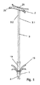
図1に示すインプラントは、遠位インプラント部1と、近位インプラント部2と、近位インプラント部と遠位インプラント部とを接続する索3とを備える。索は遠位インプラント部の遠位端から近位インプラント部に、また近位インプラント部を通って遠位インプラント部の遠位端に戻るよう誘導され、そのため索3は二重になり、2つの索部分3.1、3.2を、近位インプラント部と遠位インプラント部との間に有する。遠位インプラント部内およびその遠位端と近位端との間で、索部分3.1、3.2はシャフト13内に誘導され、遠位インプラント部の遠位のボス5によって固定される。
The implant shown in FIG. 1 includes a
代替の実施形態では、ボスの代わりに、遠位インプラント部を索に固定するために、例えばクリンプ、溶接などの他の技術を使用することができる。 In an alternative embodiment, instead of the boss, other techniques such as crimping, welding, etc. can be used to secure the distal implant to the chordee.
遠位インプラント部1は、索用の長手方向の貫通開口部を有するシャフト13と、後方に突出し、半径方向外側に曲がる複数の脚部15とを備える。
The
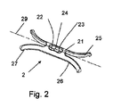
近位インプラント部2を、図2に幾分かより詳細に示している。近位インプラント部は、長手軸線29を規定する細長いものである。近位インプラント部は、中央本体21と、中央本体と一体で、中央本体から外側に延びている4つのアーム25とを有する。
The
中央本体およびアームの下側は、移植後の弁尖組織に移植後に載る当接面を形成する。 The central body and the underside of the arm form a contact surface that rests on the apical tissue after transplantation.
索3は、近位インプラント部2と遠位インプラント部1とを互いに機械的に連結し、これらのインプラント部の間の最大距離を規定する。この目的のために、近位インプラント部は、ブリッジ24によって分離された第1索用開口部22および第2索用開口部23を有する。索は、第1索用開口部を通ってブリッジを越えて、第2索用開口部に戻るように延び、近位インプラント部を通って輪になるようにする。ブリッジ24は、丸みを帯びた特徴を有し、索が損傷することなく容易にブリッジに沿って摺動することができるようにする。第1および第2の開口部は、当接領域の中心がそれらの開口部の間の中央に位置するように配置される。
The
開口部が近位インプラント部の中央に配置されているので、近位インプラント部に作用する索に結合される引っ張り力は、近位インプラント部にいかなるトルクをも生じさせない。 Since the opening is located in the center of the proximal implant, the pulling force attached to the cord acting on the proximal implant does not cause any torque in the proximal implant.
図示の構成では、索3は二重になり、近位インプラント部を通って輪になるが、この効果はまた、例えば、索が一方向のみであり、領域の中心のスポットに取り付けられるか、領域の中心にある単一の開口部に延びる場合にも達成できる。 In the configuration shown, the chordee is doubled and looped through the proximal implant, but this effect is also achieved, for example, if the chordee is unidirectional and can be attached to a spot in the center of the area. It can also be achieved if it extends to a single opening in the center of the area.
近位インプラント部2のアーム25は、軸線から外向きに曲げられている。それにより、近位インプラント部は、弁尖組織によって良好に支持される。当接面で、アームはそれぞれ、任意のフック特徴27を備える。
The
図3は、乳頭筋に固定された遠位インプラント部1を示す。人工の索3は、心室を通って延び、弁尖の開口部を通って延びている。近位インプラント部は、弁尖61の近位側に配置され、当接面は、弁尖組織に配置される。これにより、インプラントは、生来の腱索63が損傷している場合、さもなければ僧帽弁が十分に閉じるのに十分ではない場合、生来の腱索63を補助する。
FIG. 3 shows a
弁尖把持機構を実現する外科用器具の実施形態を図4、図5および図6に示す。図示の機構は、第1の外側の管の内部に誘導されるさらなる第2の管と、主要本体101と、顎部を形成する第1のアーム111および第2のアーム112と、主要本体101に対して摺動可能な押圧部材として形成された対応部80とを含み、取り付けられる。
Embodiments of a surgical instrument that realizes a valve leaflet gripping mechanism are shown in FIGS. 4, 5 and 6. The mechanism shown is a further second tube guided inside the first outer tube, a
最初、器具は外側の管に含まれる折り畳み位置(以下に説明する図7および図9参照)にあり、この位置から所望の(通常は左の)心房に前進させた後、外科医がそれを解放することができる。解放は、主要本体が取り付けられた第2の管に対して外側の管を引っ込めることによって実行してもよい。 Initially, the instrument is in a folded position contained in the outer tube (see FIGS. 7 and 9 described below), from which position is advanced to the desired (usually left) atrium, after which the surgeon releases it. can do. Release may be performed by retracting the outer tube relative to the second tube to which the main body is attached.
解放後、アームは図4〜図6に示す位置に回転して張り出す。これは、例えば後述するように、外科医による能動的な動作を含む機構によって行うことができる。あるいは、装置はまた、解放中に自動的に回転して張り出すように予め張力をかけることもできる。 After release, the arm rotates to the position shown in FIGS. 4 to 6 and projects. This can be done by a mechanism that involves active movement by the surgeon, for example, as described below. Alternatively, the device can also be pre-tensioned to automatically rotate and overhang during release.
回転張出位置では、第1のアームは、第1の管と第2の管によって規定される軸線120に対して、第1の角度にある。特に、第1の角度は、直角ではなく、例えば20°〜50°の間の鋭角であってもよい。第2のアーム112は、第1のアームに対して第2の角度α(90°から第1の角度を引いたもの)であり、第2のアームは軸線120にほぼ垂直である。第2のアームの近位側に向いた面122は、第1の当接面を備える。対応部80の遠位側に向いた端面81は、第2の当接面を形成する。
In the rotary overhang position, the first arm is at a first angle with respect to the axis 120 defined by the first and second tubes. In particular, the first angle may not be a right angle, but may be an acute angle, for example, between 20 ° and 50 °. The
第3の管の遠位部を構成する対応部80自体の内部に、第4の内側の管40(針の管)が誘導される。内側の管40の遠位端には、針を形成するための遠位の穿孔縁部41が設けられている。内側の管40の内部には、第5のアンカキャリア管50が存在する。アンカキャリア管の遠位端は、例えば、同日に本出願人によって出願された、房室心臓弁を修復するためのシステムを取り扱う同時係属中の出願に記載されているように、インプラントが取り付けられるアンカキャリアを形成する。キャリア管50と内側の管との間に、インプラントおよび特に索を内側の管40の縁部41から保護するために、鈍い遠位端を有するさらなる中間の管(またはスリーブ)を配置することができる。
Inside the third-enabled
この本文で言及している様々な管は、記載された部分の近位に、同心円状に誘導してもよい。プラスチック、メッシュワイヤ、レーザカットなどの適切な切込みを有する金属のような材料の管状材料を使用することができる。 The various tubes referred to in this text may be concentrically guided proximal to the section described. Tubular materials of materials such as metal with suitable cuts such as plastic, mesh wire, laser cut can be used.
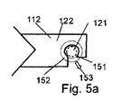
第1の当接面を有する第2のアーム112は、側面に開いた凹部121を有する。図5aでより詳細に示すように、第2のアームの形状は、第2のアームが解放状態にあるとき、主要本体101に対して前進させたときの内側の管が、第2のアームに遭遇することなく凹部を通ることができるようにしている。図5aの破線の円151は、第1のアームから突出しているときの内側の管の断面における位置を示す。第1の当接面は、対応部が主要本体101に対して前進するときに遠位側に向いた端面81が押圧可能な、面122の該当部分によって形成される。図5aにおいて、この端面の位置は略リング形状であると想定しており、152(破線)で示している。第1の当接面は、一般に、凹部に直接隣接する。図5aにおいて、軸線120は、円形領域151内の中心に延び、図面の平面に対して垂直に延びている。
The
この遠位の第2の当接面のリング形状は必須ではない。むしろ当接面は他の形状を有してもよい。特に、示された実施形態では、少なくとも図示された遠位端に向かう対応部は、弁尖がクランプされている間も近位インプラント部の解放を可能にするスリット付き管(1つまたは2つの軸線方向に延びるスリットを有する)の形状を有する。したがって、第2の当接面は、C字形または2つの平行な棒の形状(I字形)、またはL字形または単一の棒の形状さえも有することができる。 The ring shape of this distal second contact surface is not essential. Rather, the contact surface may have other shapes. In particular, in the illustrated embodiment, the corresponds portions toward the distal end that is at least shown, one tube with a slit (which also allows the release of the proximal implant portion while the leaflets are clamped or 2 It has a shape (with slits extending in one axial direction). Thus, the second contact surface can have a C-shape or the shape of two parallel rods (I-shape), or even an L-shape or even a single rod shape.
回転張出部の材料は、外科医のニーズに適合させることができる。適用可能な材料には、外科手術に合う性質の鋼またはPEEKなどのポリマベースの材料が含まれる。アームの表面は、画像化の目的のために最適化してもよい。 The material of the rotating overhang can be adapted to the needs of the surgeon. Applicable materials include polymer-based materials such as steel or PEEK with surgical properties. The surface of the arm may be optimized for imaging purposes.
図7は、折り畳み状態の装置を示し、この状態では第1のアーム111が遠位方向に真っ直ぐ(軸線方向)に延び、第1のアームの遠位端に取り付けられた第2のアームが第1のアームに沿って折り返されている、すなわち、第1のアームと平行である。操縦ワイヤ131は、主要本体101および第1のアーム111の小さな後部管腔内で誘導構造132の周りで誘導され、第2のアーム内の取付点(ボス(knot)133)に通じている。図7に矢印で示すように操縦ワイヤが引っ張られると、第1のアーム111と第2のアーム112は、回転張出位置に押し込まれる(図8)。図9に示すように、折り畳み状態になるように装置に予め張力をかけ、そのため、操縦ワイヤ131が解放されるとすぐに折り畳み状態に跳ね返るように、ばね要素が使用できる。図示された実施形態のばね要素は、第1のアーム111を軸線に平行に向けるための補強用ばね要素141と、第2のアーム112を第1のアーム111に折り込むためのねじりばね142とで構成される。
FIG. 7 shows a device in a folded state, in which the
図10〜図15は、装置によって実行されるプロセスを示す。図10は、アーム111、112が回転張出位置にあり、対応部80が第1の当接面を押圧する構成を示している。この構成は、第1の当接面と第2の当接面との間で弁尖の外側部分をクランプすると想定される。次に、図11に示すように、遠位インプラント部1および近位インプラント部2を有するアンカキャリアを含む内側の管40は、遠位方向に向かって移動することによって突出する。これにより、その管は弁尖を穿孔し、組織、特に乳頭筋などの筋組織を穿孔するまでさらに前進する。次に、アンカキャリアをそのまま保持しながら、内側の管40を後退させて、遠位インプラント部1を解放し、遠位インプラント部は脚部の効果により、組織内に棘状の様式で固定される(図12)。
10 to 15 show the processes performed by the device. 10, the
アンカキャリアを包囲する前述の種類の任意選択のスリーブ(図示せず)を使用して、内側の管40を後退させながらインプラントを保護できるが、それは、遠位の穿孔縁部41を有する内側の管を、スリーブがインプラント部を保護した状態で最初に引き込み、その後にのみスリーブが後退するという点においてのことである。
An optional sleeve of the aforementioned type (not shown) surrounding the anchor carrier can be used to protect the implant while retracting the
遠位インプラント部1が解放された後、内側の管40は、把持およびクランプされた弁尖の近位側に近位インプラント部2がくるまで、近位インプラント部2を保持するアンカキャリア(および任意選択で適用可能ならば、スリーブも)とともに、さらに後退させる(図13)。
After the
その後、内側の管は、アンカキャリアが近位インプラント部2を解放する位置に留まる間、さらに後退する(図14)。また、このステップは、内側の管40を最初に引っ込め、その時にのみアンカを保護するためにスリーブ(適用可能な場合)を引き込むサブステップを任意選択に含んでもよい。
The inner tube then retracts further while the anchor carrier remains in a position to release the proximal implant 2 (FIG. 14). This step may also optionally include a sub-step of retracting the
その結果、インプラントが設置される。弁尖を、対応部80を引っ込めることによって解放し得る(図15)。次に、索は、図5aの二重矢印153の方向に逃れることによって、第2のアームに対して動くことができる。その後、アームは、図7および図9に示す位置に折り込まれ、外側の管内に引き込まれる。
As a result, the implant is installed. The leaflets may be released by retracting the corresponds section 80 (FIG. 15). The chordee can then move relative to the second arm by escaping in the direction of
Claims (12)
軸線方向を規定する管の軸線(120)を有する第1の管と、
前記第1の管内に配置され、主要本体(101)および回転張出部を備える弁尖把持構造であり、前記回転張出部が、前記主要本体(101)に取り付けられた第1のアーム(111)と、第2のアーム(112)とを有し、前記第2のアーム(112)が前記第1のアームに対して回転式に取り付けられており、前記第1のアーム(111)が前記主要本体(101)に対して回転式に取り付けられている、弁尖把持構造と
を備え、
前記第2のアーム(112)が、前記第1のアームおよび前記第2のアーム(112)の回転張出位置において、近位側に向いた第1の当接面(122)を備え、
前記弁尖把持構造が、前記第1の管から解放可能である管の遠位部をなす対応部(80)をさらに備え、前記対応部が、前記主要本体(101)に対して軸線方向に移動可能であり、前記対応部(80)が、遠位方向に向かう力によって前記第1の当接面を押圧可能な遠位側に向いた第2の当接面(81)を備え、前記弁尖把持構造が、前記第1の当接面と前記第2の当接面との間で前記心臓弁の弁尖をクランプすることができ、
前記第2のアーム(112)は、凹部(121)を有し、前記第1のアーム(111)および前記第2のアーム(112)の前記回転張出位置において、前記第2のアームは、前記管の軸線(120)が前記凹部を通るように延びて、前記対応部(80)の内部から解放された人工の索が、前記弁尖がクランプされている間に前記凹部を貫通して延びること、および横方向の相対的な動きによって前記凹部(121)から解放されることを可能にする、器具において、
折り畳み位置において、前記第1のアーム(111)が、前記主要本体(101)の軸線方向遠位側に延びており、前記第2のアーム(112)が、前記第1のアーム(111)と平行になるように折り返されていることを特徴とする、器具。 A surgical instrument for repairing atrioventricular heart valves in a minimally invasive manner,
A first tube having an axis (120) of the tube that defines the axial direction,
It is a valve tip gripping structure that is arranged in the first pipe and includes a main body (101) and a rotary overhang, and the rotary overhang is a first arm (101) attached to the main body (101). 111) and a second arm (112), the second arm (112) is rotatably attached to the first arm, and the first arm (111) It has a valve leaflet gripping structure that is rotatably attached to the main body (101).
The second arm (112) comprises a first contact surface (122) facing proximally at the rotational overhang positions of the first arm and the second arm (112).
The valve leaflet gripping structure further comprises a corresponding portion (80) forming a distal portion of the tube that can be released from the first tube, the corresponding portion axially relative to the main body (101). The movable portion (80) includes a second contact surface (81) facing the distal side capable of pressing the first contact surface by a force toward the distal direction. The valve leaflet gripping structure can clamp the valve leaflet of the heart valve between the first contact surface and the second contact surface.
Said second arm (112) has a recess (121), in the rotation projecting position of said first arm (111) and said second arm (112), said second arm, axis before Symbol tube (120) extends so as to pass through the recess, the artificial chordae released from the inside of the corresponding portion (80), the recess penetrates while leaflets said valve is clamped In an appliance that allows it to extend and be released from the recess (121) by relative lateral movement.
At the folded position, the first arm (111) extends distal to the axial direction of the main body (101), and the second arm (112) and the first arm (111) An instrument characterized by being folded back in parallel.
Applications Claiming Priority (3)
| Application Number | Priority Date | Filing Date | Title |
|---|---|---|---|
| CH15352015 | 2015-10-21 | ||
| CH01535/15 | 2015-10-21 | ||
| PCT/CH2016/000138 WO2017066890A1 (en) | 2015-10-21 | 2016-10-19 | Medical instrument and method for heart valve repair |
Publications (3)
| Publication Number | Publication Date |
|---|---|
| JP2018533398A JP2018533398A (en) | 2018-11-15 |
| JP2018533398A5 JP2018533398A5 (en) | 2019-11-28 |
| JP6933421B2 true JP6933421B2 (en) | 2021-09-08 |
Family
ID=57199849
Family Applications (1)
| Application Number | Title | Priority Date | Filing Date |
|---|---|---|---|
| JP2018518491A Active JP6933421B2 (en) | 2015-10-21 | 2016-10-19 | Medical devices and methods for heart valve repair |
Country Status (5)
| Country | Link |
|---|---|
| US (1) | US10799357B2 (en) |
| EP (1) | EP3364884B1 (en) |
| JP (1) | JP6933421B2 (en) |
| CN (1) | CN108289662B (en) |
| WO (1) | WO2017066890A1 (en) |
Families Citing this family (21)
| Publication number | Priority date | Publication date | Assignee | Title |
|---|---|---|---|---|
| GB2536538B (en) | 2014-09-17 | 2018-07-18 | Cardiomech As | Anchor for implantation in body tissue |
| US9877833B1 (en) | 2016-12-30 | 2018-01-30 | Pipeline Medical Technologies, Inc. | Method and apparatus for transvascular implantation of neo chordae tendinae |
| US10925731B2 (en) | 2016-12-30 | 2021-02-23 | Pipeline Medical Technologies, Inc. | Method and apparatus for transvascular implantation of neo chordae tendinae |
| US11083580B2 (en) | 2016-12-30 | 2021-08-10 | Pipeline Medical Technologies, Inc. | Method of securing a leaflet anchor to a mitral valve leaflet |
| DE102017002974B4 (en) * | 2017-03-28 | 2024-08-08 | Immanuel Albertinen Diakonie Ggmbh | Heart valve implant, suitable for use in minimally invasive surgery to repair a heart valve and/or a heart valve leaflet on the beating heart and heart valve implant system |
| CN111163703B (en) * | 2017-10-12 | 2023-12-15 | 克里斯托夫梅斯克两合公司 | Pericardial clamp and method for implantation of temporary heart assist system |
| US11376127B2 (en) * | 2017-12-20 | 2022-07-05 | W. L. Gore & Associates, Inc. | Artificial chordae tendineae repair devices and delivery thereof |
| CN109009490B (en) * | 2018-09-13 | 2023-11-24 | 中国医科大学附属盛京医院 | Flexible recoverable puncture anchor and fixer thereof |
| WO2020109594A1 (en) * | 2018-11-29 | 2020-06-04 | Cardiomech As | Device for heart repair |
| EP3886726A1 (en) * | 2018-11-29 | 2021-10-06 | Cardiomech AS | Device for heart repair |
| JP2022513793A (en) | 2018-12-12 | 2022-02-09 | パイプライン メディカル テクノロジーズ, インコーポレイテッド | Methods and equipment for mitral valve chordae tendineae repair |
| US20200188115A1 (en) * | 2018-12-13 | 2020-06-18 | Medtronic Vascular, Inc. | Heart valve repair tool and techniques |
| US20220183841A1 (en) | 2019-03-19 | 2022-06-16 | Coremedic Gmbh | Instrument for repairing an atrioventricular heart valve |
| EP3993712A1 (en) | 2019-07-03 | 2022-05-11 | Boston Scientific Scimed, Inc. | Devices, systems, and methods for adjustably tensioning an artificial chordae tendineae between a leaflet and a papillary muscle or heart wall |
| EP3993709B1 (en) | 2019-07-03 | 2024-08-28 | Boston Scientific Scimed, Inc. | System for anchoring an artificial chordae tendineae to a papillary muscle or heart wall |
| CN114072100A (en) * | 2019-07-03 | 2022-02-18 | 波士顿科学国际有限公司 | Devices, systems, and methods for artificial chordae tendineae |
| US11850152B2 (en) | 2019-07-03 | 2023-12-26 | Boston Scientific Scimed, Inc. | Devices, systems, and methods for artificial chordae tendineae |
| US11648117B2 (en) | 2019-07-12 | 2023-05-16 | Boston Scientific Scimed, Inc. | Devices, systems, and methods for clamping a leaflet of a heart valve |
| JP2023538789A (en) * | 2020-09-30 | 2023-09-11 | ボストン サイエンティフィック サイムド,インコーポレイテッド | Apparatus, system, and method for adjusting tension on artificial chordae within the heart |
| GB2601146B (en) * | 2020-11-19 | 2023-02-22 | Cardiomech As | Device for heart repair |
| CN117243654B (en) * | 2023-10-10 | 2024-05-28 | 上海声拓医疗科技有限公司 | Loading and delivery assembly for prosthetic devices |
Family Cites Families (15)
| Publication number | Priority date | Publication date | Assignee | Title |
|---|---|---|---|---|
| WO2000040159A1 (en) * | 1998-12-31 | 2000-07-13 | Yeung Teresa T | Tissue fastening devices and delivery means |
| EP1253860A4 (en) * | 2000-02-09 | 2006-04-26 | Eva Corp | Surgical fastener |
| US8956407B2 (en) * | 2000-09-20 | 2015-02-17 | Mvrx, Inc. | Methods for reshaping a heart valve annulus using a tensioning implant |
| US7316706B2 (en) * | 2003-06-20 | 2008-01-08 | Medtronic Vascular, Inc. | Tensioning device, system, and method for treating mitral valve regurgitation |
| US20070004995A1 (en) | 2005-06-30 | 2007-01-04 | Horn Jeffrey L | Swab device and kit for the delivery of blood clotting materials to a wound site |
| US20070049952A1 (en) * | 2005-08-30 | 2007-03-01 | Weiss Steven J | Apparatus and method for mitral valve repair without cardiopulmonary bypass, including transmural techniques |
| WO2007062054A2 (en) | 2005-11-21 | 2007-05-31 | The Brigham And Women's Hospital, Inc. | Percutaneous cardiac valve repair with adjustable artificial chordae |
| US20110011917A1 (en) | 2008-12-31 | 2011-01-20 | Hansen Medical, Inc. | Methods, devices, and kits for treating valve prolapse |
| US8475525B2 (en) * | 2010-01-22 | 2013-07-02 | 4Tech Inc. | Tricuspid valve repair using tension |
| WO2012040865A1 (en) | 2010-10-01 | 2012-04-05 | Alberto Weber | Medical apparatus and method for heart valve repair |
| WO2013003228A1 (en) * | 2011-06-27 | 2013-01-03 | University Of Maryland, Baltimore | Transapical mitral valve repair device |
| US8900295B2 (en) * | 2011-09-26 | 2014-12-02 | Edwards Lifesciences Corporation | Prosthetic valve with ventricular tethers |
| ES2785667T3 (en) * | 2012-01-31 | 2020-10-07 | Mitral Valve Tech Sarl | Mitral valve restraint devices and systems |
| US9301842B2 (en) * | 2013-01-31 | 2016-04-05 | St. Jude Medical, Inc. | Method and device for heart valve repair |
| FR2998167B1 (en) * | 2013-03-20 | 2015-01-09 | Marco Vola | DEVICE FOR PERFORMING AN ANNULOPLASTY BY THE TRANSAPICAL PATH OF THE MITRAL VALVE |
-
2016
- 2016-10-19 WO PCT/CH2016/000138 patent/WO2017066890A1/en active Application Filing
- 2016-10-19 CN CN201680061670.1A patent/CN108289662B/en active Active
- 2016-10-19 US US15/768,887 patent/US10799357B2/en active Active
- 2016-10-19 EP EP16785327.4A patent/EP3364884B1/en active Active
- 2016-10-19 JP JP2018518491A patent/JP6933421B2/en active Active
Also Published As
| Publication number | Publication date |
|---|---|
| US10799357B2 (en) | 2020-10-13 |
| WO2017066890A1 (en) | 2017-04-27 |
| JP2018533398A (en) | 2018-11-15 |
| US20180303614A1 (en) | 2018-10-25 |
| EP3364884B1 (en) | 2020-02-05 |
| EP3364884A1 (en) | 2018-08-29 |
| CN108289662B (en) | 2021-03-12 |
| CN108289662A (en) | 2018-07-17 |
Similar Documents
| Publication | Publication Date | Title |
|---|---|---|
| JP6933421B2 (en) | Medical devices and methods for heart valve repair | |
| JP6935927B2 (en) | Medical implants and methods for heart valve repair | |
| US20240108327A1 (en) | Suturing devices and methods for suturing an anatomic valve | |
| JP6798753B2 (en) | Medical devices and methods for heart valve repair | |
| EP3169245B1 (en) | Medical apparatus for heart valve repair | |
| JP2018531092A6 (en) | Medical implants and methods for heart valve repair | |
| US20200100898A1 (en) | Device for performing or preparing for a mitral valve annuloplasty by a transfemoral approach | |
| CA2854116C (en) | Apparatuses and methods for cutting a tissue bridge and/or removing a heart valve clip or suture | |
| JP6595197B2 (en) | Suture passer designed for use in tight areas | |
| CN110325125A (en) | The method and apparatus that intravascular for newborn chordae tendineae is implanted into | |
| JP2018531093A6 (en) | Medical instruments and methods for heart valve repair | |
| CN109106412A (en) | For the fixed device of medical treatment with fixing component fixed object | |
| JP2022526046A (en) | A device for repairing the atrioventricular heart valve | |
| GB2579387A (en) | Device for heart repair | |
| CN113274167A (en) | Edge-to-edge repair device and edge-to-edge repair system |
Legal Events
| Date | Code | Title | Description |
|---|---|---|---|
| A521 | Request for written amendment filed |
Free format text: JAPANESE INTERMEDIATE CODE: A523 Effective date: 20180522 |
|
| RD04 | Notification of resignation of power of attorney |
Free format text: JAPANESE INTERMEDIATE CODE: A7424 Effective date: 20190919 |
|
| A521 | Request for written amendment filed |
Free format text: JAPANESE INTERMEDIATE CODE: A523 Effective date: 20191016 |
|
| A621 | Written request for application examination |
Free format text: JAPANESE INTERMEDIATE CODE: A621 Effective date: 20191016 |
|
| A977 | Report on retrieval |
Free format text: JAPANESE INTERMEDIATE CODE: A971007 Effective date: 20200918 |
|
| A131 | Notification of reasons for refusal |
Free format text: JAPANESE INTERMEDIATE CODE: A131 Effective date: 20201020 |
|
| A601 | Written request for extension of time |
Free format text: JAPANESE INTERMEDIATE CODE: A601 Effective date: 20210120 |
|
| A521 | Request for written amendment filed |
Free format text: JAPANESE INTERMEDIATE CODE: A523 Effective date: 20210319 |
|
| TRDD | Decision of grant or rejection written | ||
| A01 | Written decision to grant a patent or to grant a registration (utility model) |
Free format text: JAPANESE INTERMEDIATE CODE: A01 Effective date: 20210720 |
|
| A61 | First payment of annual fees (during grant procedure) |
Free format text: JAPANESE INTERMEDIATE CODE: A61 Effective date: 20210813 |
|
| R150 | Certificate of patent or registration of utility model |
Ref document number: 6933421 Country of ref document: JP Free format text: JAPANESE INTERMEDIATE CODE: R150 |
|
| R250 | Receipt of annual fees |
Free format text: JAPANESE INTERMEDIATE CODE: R250 |