EP3553799B1 - Procédé de fabrication d'un noyau de fer - Google Patents
Procédé de fabrication d'un noyau de fer Download PDFInfo
- Publication number
- EP3553799B1 EP3553799B1 EP17877845.2A EP17877845A EP3553799B1 EP 3553799 B1 EP3553799 B1 EP 3553799B1 EP 17877845 A EP17877845 A EP 17877845A EP 3553799 B1 EP3553799 B1 EP 3553799B1
- Authority
- EP
- European Patent Office
- Prior art keywords
- laminate
- thin strips
- laminated
- nanocrystal thin
- iron core
- Prior art date
- Legal status (The legal status is an assumption and is not a legal conclusion. Google has not performed a legal analysis and makes no representation as to the accuracy of the status listed.)
- Active
Links
Images

Classifications
-
- H—ELECTRICITY
- H02—GENERATION; CONVERSION OR DISTRIBUTION OF ELECTRIC POWER
- H02K—DYNAMO-ELECTRIC MACHINES
- H02K1/00—Details of the magnetic circuit
- H02K1/02—Details of the magnetic circuit characterised by the magnetic material
-
- H—ELECTRICITY
- H01—ELECTRIC ELEMENTS
- H01F—MAGNETS; INDUCTANCES; TRANSFORMERS; SELECTION OF MATERIALS FOR THEIR MAGNETIC PROPERTIES
- H01F1/00—Magnets or magnetic bodies characterised by the magnetic materials therefor; Selection of materials for their magnetic properties
- H01F1/01—Magnets or magnetic bodies characterised by the magnetic materials therefor; Selection of materials for their magnetic properties of inorganic materials
- H01F1/03—Magnets or magnetic bodies characterised by the magnetic materials therefor; Selection of materials for their magnetic properties of inorganic materials characterised by their coercivity
- H01F1/12—Magnets or magnetic bodies characterised by the magnetic materials therefor; Selection of materials for their magnetic properties of inorganic materials characterised by their coercivity of soft-magnetic materials
- H01F1/14—Magnets or magnetic bodies characterised by the magnetic materials therefor; Selection of materials for their magnetic properties of inorganic materials characterised by their coercivity of soft-magnetic materials metals or alloys
- H01F1/147—Alloys characterised by their composition
- H01F1/153—Amorphous metallic alloys, e.g. glassy metals
- H01F1/15333—Amorphous metallic alloys, e.g. glassy metals containing nanocrystallites, e.g. obtained by annealing
-
- H—ELECTRICITY
- H01—ELECTRIC ELEMENTS
- H01F—MAGNETS; INDUCTANCES; TRANSFORMERS; SELECTION OF MATERIALS FOR THEIR MAGNETIC PROPERTIES
- H01F3/00—Cores, Yokes, or armatures
- H01F3/04—Cores, Yokes, or armatures made from strips or ribbons
-
- H—ELECTRICITY
- H01—ELECTRIC ELEMENTS
- H01F—MAGNETS; INDUCTANCES; TRANSFORMERS; SELECTION OF MATERIALS FOR THEIR MAGNETIC PROPERTIES
- H01F41/00—Apparatus or processes specially adapted for manufacturing or assembling magnets, inductances or transformers; Apparatus or processes specially adapted for manufacturing materials characterised by their magnetic properties
- H01F41/02—Apparatus or processes specially adapted for manufacturing or assembling magnets, inductances or transformers; Apparatus or processes specially adapted for manufacturing materials characterised by their magnetic properties for manufacturing cores, coils, or magnets
- H01F41/0206—Manufacturing of magnetic cores by mechanical means
- H01F41/0213—Manufacturing of magnetic circuits made from strip(s) or ribbon(s)
- H01F41/0226—Manufacturing of magnetic circuits made from strip(s) or ribbon(s) from amorphous ribbons
-
- H—ELECTRICITY
- H02—GENERATION; CONVERSION OR DISTRIBUTION OF ELECTRIC POWER
- H02K—DYNAMO-ELECTRIC MACHINES
- H02K1/00—Details of the magnetic circuit
- H02K1/06—Details of the magnetic circuit characterised by the shape, form or construction
- H02K1/12—Stationary parts of the magnetic circuit
- H02K1/14—Stator cores with salient poles
- H02K1/146—Stator cores with salient poles consisting of a generally annular yoke with salient poles
-
- H—ELECTRICITY
- H02—GENERATION; CONVERSION OR DISTRIBUTION OF ELECTRIC POWER
- H02K—DYNAMO-ELECTRIC MACHINES
- H02K1/00—Details of the magnetic circuit
- H02K1/06—Details of the magnetic circuit characterised by the shape, form or construction
- H02K1/12—Stationary parts of the magnetic circuit
- H02K1/18—Means for mounting or fastening magnetic stationary parts on to, or to, the stator structures
- H02K1/185—Means for mounting or fastening magnetic stationary parts on to, or to, the stator structures to outer stators
-
- H—ELECTRICITY
- H02—GENERATION; CONVERSION OR DISTRIBUTION OF ELECTRIC POWER
- H02K—DYNAMO-ELECTRIC MACHINES
- H02K15/00—Processes or apparatus specially adapted for manufacturing, assembling, maintaining or repairing of dynamo-electric machines
- H02K15/02—Processes or apparatus specially adapted for manufacturing, assembling, maintaining or repairing of dynamo-electric machines of stator or rotor bodies
Definitions
- the technical field relates to a method to produce an iron core in which soft magnetic thin strips are laminated.
- a manufacturing process of a stator core disclosed in Japanese Patent Unexamined Publication No. 6-145917 is as follows. First, an amorphous alloy thin strip produced by a liquid quenching method such as a single roll method or a twin roll method is processed into a predetermined shape by a method such as winding, cutting, punching, and etching. Next, the processed product is formed by laminating.
- a liquid quenching method such as a single roll method or a twin roll method
- a method such as winding, cutting, punching, and etching.
- An alloy ribbon and a member using it is disclosed in Japanese Patent Application Publication No. 2004-353090 .
- An annular magnetic core using iron-based nanocrystalline soft magnetic alloy and a magnetic component using said annular magnetic core is disclosed in the European Patent Application Publication No. 2 958 116 .
- a bulk amorphous metal inductive device is disclosed in the US Patent Application Publication No. 2004-0085173 .
- a selective etching process for cutting amorphous metal shapes and components made thereof is disclosed in the US Patent Application Publication No. 2004-0212269 .
- the amorphous alloy thin strip in order to make the amorphous alloy thin strip to be a nanocrystal thin strip which is supposed to have better soft magnetic characteristics, further heat treatment is required.
- the thickness of the nanocrystal thin strip is about one-tenth of the thickness of a commonly used electromagnetic steel plate. Therefore, when the heat treatment is performed one by one, the handling amount is about ten times higher than the one in the related art.
- An object of the disclosure is to solve the problems in the related art, and to provide an iron core and a motor of nanocrystal thin strips with stable magnetic characteristics without impairing productivity.
- a method is defined in the appended claim and allows to obtain an iron core including a laminate in which a plurality of nanocrystal thin strips are laminated, a board, and a fastener that fastens the laminate and the board, in which at least one of upper and lower surfaces of the laminate has a colored oxide film and an uncolored oxide film is used. Moreover, the iron core having a region of the colored oxide film wider than a region of the uncolored oxide film region is used. Furthermore, a motor using the above-described iron core as a stator is used.
- the nanocrystal thin strips obtained by performing heat treatment on the laminated amorphous alloy thin strips at once are laminated, it is possible to provide an iron core and a motor of nanocrystal thin strips with stable magnetic characteristics without impairing productivity.
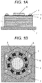
- FIGs. 1A and 1B are views showing a configuration of an iron core and a motor according to Embodiment 1 of the disclosure, specifically, a brushless motor.
- FIG. 1A is a side view of an iron core and a motor
- FIG. 1B is a top view.
- an iron core includes laminate 1 of nanocrystal thin strips 2 and a fastening mechanism composed of bolt 5 and fastener 6 penetrating laminate 1 and fastening them to metal board 7.
- the iron core to which winding 9 is applied is a stator.
- Rotor 8 is provided in an inner diameter portion of the stator, and the motor is driven by energizing.
- Laminate 1 is an iron core member of the stator of the motor. Laminate 1 becomes laminate 1 of nanocrystal thin strips 2 by laminating nanocrystal thin strips 2 which are amorphous alloy thin strips without using an adhesive therebetween and subjecting them to heat treatment. A space factor can be increased by not using an adhesive.
- the amorphous alloy thin strip before the heat treatment is an iron alloy having a plate thickness of 10 ⁇ m to 60 ⁇ m and containing at least one of boron and silicon.
- the amorphous alloy thin strip is manufactured by quenching by pouring the melted iron alloy onto a surface of a rotating cooling drum and stretching it into a ribbon shape.
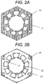
- a region of invisible oxide film 12 showing metallic luster may remain in a vicinity of the site.
- a region of visible oxide film 11 is wider than the region of invisible oxide film 12.
- Through-hole 10 is a through-hole for inserting bolt 5. Visible colors tend to obtain good magnetic characteristics in the range visible to bare eyes as shiny brown, blue, violet, and the like. However, there is no strict correlation between the color and magnetic characteristics.
- Nanocrystal thin strip 2 of FIG. 2B shows an interlayer surface of laminate 1. It has the region of invisible oxide film 12 showing metallic luster. Between the surfaces of nanocrystal thin strips 2, nanocrystal thin strips 2 come into contact with each other, or the gap between nanocrystal thin strips 2 becomes very narrow. Therefore, the atmosphere and the like can barely enter between the surfaces of nanocrystal thin strips 2. Therefore, as before the heat treatment, it is assumed that the region of invisible oxide film 12 showing metallic luster remains on the surface of nanocrystal thin strip 2.
- a visible, that is, a colored oxide film and an invisible, that is, an uncolored oxide film have almost the same thickness.
- the outer periphery of the region of invisible oxide film 12 showing metallic luster is surrounded by the region of visible oxide film 11. It is considered that this is the influence of the atmosphere entering through a small gap between the layers of nanocrystal thin strips 2 because the outer periphery of nanocrystal thin strip 2 is close. Even if laminated nanocrystal thin strips 2 are heat treated, if the number of the pieces is the upper limit or lower, each of nanocrystal thin strips 2 obtains predetermined magnetic characteristics. When the number of pieces exceeds the upper limit, the difference in temperature distribution in the thickness direction increases, and thereby good magnetic characteristics cannot be obtained.
- nanocrystal thin strips 2 on the surface of laminate 1 have mainly visible oxide film 11 on one side and mainly invisible oxide film 12 showing metallic luster on the other side.
- Nanocrystal thin strips 2 inside laminate 1 have mainly invisible oxide film 12 showing metallic luster on both sides.
- Single nanocrystal thin strip 2 of laminate 1 has mainly the visible oxide film on both sides.
- Nanocrystal thin strips 2 of laminate 1 may include any one of above-described nanocrystal thin strips 2.
- the heat generated by self-heating accompanied with crystallization is likely to be accumulated between laminated nanocrystal thin strips 2. Due to the excessive temperature rise, not only the magnetic characteristics are rather deteriorated, but also it becomes brittle and easily damaged. Although it depends on target magnetic characteristics and heat treatment conditions, good magnetic characteristics can be obtained even when ten or more nanocrystal thin strips 2 are laminated and heat treated.
- a portion of the region is pressed by fastener 6 and heat treated without using an adhesive between nanocrystal thin strips 2, so that the heat treatment can be performed in a laminated state, and characteristics can be obtained.
- processes such as heat treatment and lamination can be processed at once with ten or more pieces. Since the plate thickness of nanocrystal thin strip 2 is as thin as about one-tenth of an electromagnetic steel plate, there is a problem that the productivity deteriorates to about one-tenth when treated one by one. However, since ten or more pieces can be processed at once, this problem can be solved. Therefore, it is possible to manufacture laminate 1 of nanocrystal thin strips 2 with stable magnetic characteristics without impairing the productivity.
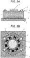
- FIGs. 3A and 3B are views showing configurations of an iron core and a motor according to Embodiment 2 of the disclosure.
- FIG. 3A is a side view of the iron core and motor
- FIG. 3B is a top view.
- FIGs. 3A and 3B are different from Embodiment 1 in that metal plate 4 is provided between laminate 1 in which nanocrystal thin strips 2 are laminated, and bolt 5 and fastener 6 which is a washer.
- nanocrystal thin strip 2 is brittle, when the same soft magnetic material electromagnetic steel plate is used for metal plate 4, nanocrystal thin strip 2 can be protected from the fastening force from bolt 5 and fastener 6, the tightening force of winding 9, or other external forces.
- metal plate 4 As another material for metal plate 4, as long as it is a nonmagnetic material, any materials not affecting the magnetic characteristics of the iron core can be used.
- metal plate 4 is provided above and below laminate 1, either one may be provided as long as the object can be achieved.
- metal plate 4 is provided on the surface thereof.
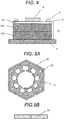
- FIG. 4 is a side view of an iron core and a motor according to Embodiment 3 of the disclosure.
- FIG. 4 is different from Embodiment 1 in that the entire laminated portion 20 has a three-stage structure in which same two first laminates 21a and 21b having a predetermined number of nanocrystal thin strips 2 and second laminate 22 having a smaller number of predetermined pieces are laminated.
- nanocrystal thin strips 2 are heat treated, it is difficult to secure temperature uniformity in the lamination direction when the number of laminated nanocrystal thin strips 2 increases, so that the width of the distribution of various magnetic characteristics increases between nanocrystal thin strips 2. Therefore, there is a limit in the laminated thickness of nanocrystal thin strips 2, and the heat treatment is performed for each laminate having a predetermined number of laminated pieces.
- laminated portion 20 is formed by laminating a plurality of laminates.
- the thickness of laminated portion 20 is thicker than a single laminate, one or plurality of laminates are laminated.
- the lamination amount of nanocrystal thin strip 2 in laminated portion 20 is controlled by the weight or the thickness at the time of fastening. Strictly speaking, since each nanocrystal thin strip 2 has different plate thicknesses, it is difficult to keep the thickness to be constant in controlling the number of laminated pieces.
- first, two first laminates 21a and 21b are laminated and the weight is measured. After confirming that the weight when another first laminate 21a or first laminate 21b is laminated exceeds a predetermined weight, second laminate 22 having less number of pieces than first laminate 21a and first laminate 21b is laminated to adjust the difference in weight. Since various values are generated in difference in weight, a plurality of laminates having different numbers of pieces or weights are prepared in advance, and second laminate 22 having an appropriate weight is laminated according to the difference in weight. In the case of thickness control, the difference in thickness can be adjusted similarly.
- Second laminate 22 having a smaller number of nanocrystal thin strips 2 than first laminate 21a, 21b having a larger number of nanocrystal thin strips 2 has a smaller number of pieces, so a more uniform heat treatment can be performed. Therefore, the magnetic characteristics are more stable. As a result, second laminate 22 not only can adjust the difference in weight and thickness but also stabilizes the magnetic characteristics.
- metal plate 4 may be provided between laminated portion 20 and a fastener including bolt 5 and fastener 6.
- FIG. 5A is a top view of first laminate 21 or second laminate 22, and FIG. 5B is a side view.
- Adhesive 23 is applied to the outer periphery of first laminate 21 and second laminate 22 and cured.
- An objective of providing adhesive 23 is to integrate first laminate 21 or second laminate 22 so that it can be easily handled. Therefore, as long as the integration can be secured, the bonding place may bond the entire outer periphery as shown in FIGs. 5A and 5B , partially bond the outer periphery, bond other inner portion such as a laminated end surface, or bond between layers of nanocrystal thin strip.
- the amorphous alloy thin strip may be bonded first to form first laminate 21 and second laminate 22, and then heat treatment may be performed, or nanocrystal thin strip 2 may be laminated and bonded.
- bonding between layers of the amorphous alloy thin strip causes disadvantages such as lowering the space factor, deteriorating heat conduction in the lamination direction during the heat treatment, increasing the width of distribution of the magnetic characteristics between nanocrystal thin strips 2, or requiring materials and time for interlayer bonding.
- adhesive 23 There is no particular restriction on the kind of adhesive 23. However, since it is often heated to 350°C or higher by the heat treatment, a polyimide-based adhesive with high heat resistance is desirable. When an adhesive with low heat resistance temperature such as an epoxy-based adhesive is used, the thermal history remains in the adhesive. A room temperature curing type or ultraviolet curing type adhesive may be used.
- FIG. 6A is a top view of a mechanically fastened laminate according to Embodiment 4 of the disclosure
- FIG. 6B is a cross-sectional view taken along line A-A' of FIG. 6A.
- FIGs. 6A and 6B are different from Embodiment 3 in that two portions are fixed by caulking member 24.
- the bonding causes disadvantages such as the magnetic characteristics being affected by other than the heat treatment due to the heating for curing or long treatment time for curing.
- mechanical means such as caulking
- the mechanical fastening method may be eyelets or a mechanism sandwiching the laminated end surface.
- FIG. 7 is a side view of an iron core and a motor according to Embodiment 5 of the disclosure.
- FIG. 7 is different from FIG. 4 of Embodiment 3 in that laminated portion 25 is formed by laminating two first laminates 21a and 21b having the same number of laminated nanocrystal thin strips 2 and layer 26 in which nanocrystal thin strips are laminated one by one instead of taking the form of a laminate in which nanocrystal thin strips 2 are fixed.
- the lamination amount of nanocrystal thin strips 2 in laminated portion 25 is controlled by the weight or the thickness at the time of fastening.
- first laminates 21a and 21b are laminated and the weight is measured first, and the difference in weight is adjusted by laminating nanocrystal thin strips 2 one by one. Therefore, the number of laminated layers 26 in which the nanocrystal thin strips are laminated is from one or more to less than the number of laminated layers of first laminates 21a and 21b.
- Nanocrystal thin strips 2 to be added may be heat treated one by one in separate process or may be taken one by one from first laminates 21a and 21b before the fixation and laminated. Nanocrystal thin strips 2 heat treated one by one are in a state having mainly visible oxide film 11 shown in FIG. 2A on both sides. There are two kinds of appearance of nanocrystal thin strip 2 in the case of extracting first laminates 21a and 21b before the fixation. One kind has one surface in a state shown in FIG. 2A and the other surface in a state having mainly invisible oxide film 12 showing metallic luster shown in FIG. 2B . Both sides are in the state of FIG. 2B in the other kind. Accordingly, layer 26 in which the nanocrystal thin strips are laminated, including any one kind or two or more kinds of these three kinds of nanocrystal thin strips is formed.
- metal plate 4 may be provided between laminated portion 25 and a fastener including bolt 5 and fastener 6.
- Embodiments 1 to 5 can be combined within the scope of the appended claim.
- the iron core according to the disclosure is useful as a stator of a motor. Furthermore, the iron core according to the disclosure can also be applied to applications of electronic components such as transformers, other than motors.
Landscapes
- Engineering & Computer Science (AREA)
- Power Engineering (AREA)
- Manufacturing & Machinery (AREA)
- Chemical & Material Sciences (AREA)
- Materials Engineering (AREA)
- Inorganic Chemistry (AREA)
- Crystallography & Structural Chemistry (AREA)
- Physics & Mathematics (AREA)
- Electromagnetism (AREA)
- Dispersion Chemistry (AREA)
- Iron Core Of Rotating Electric Machines (AREA)
- Manufacture Of Motors, Generators (AREA)
- Soft Magnetic Materials (AREA)
- Manufacturing Cores, Coils, And Magnets (AREA)
Claims (1)
- Procédé pour produire un noyau de fer comprenant un stratifié (1), le procédé comprenant les étapes de :- stratification d'une pluralité de bandes minces en alliage amorphe sans utilisation d'adhésif ;- fixation du stratifié sur une plaquette métallique avec un mécanisme de fixation comprenant un boulon (5) et un dispositif de fixation (6) pénétrant dans le stratifié (1) ;- soumission du stratifié (1) à un traitement à la chaleur pour que soit obtenu un stratifié (1) dans lequel une pluralité de bandes minces de nanocristal (2) sont stratifiées et dans lequel au moins l'une parmi les surfaces supérieure et inférieure du stratifié a un film d'oxyde coloré (11) et un film d'oxyde non coloré (12) ;dans lequel les bandes minces amorphes avant traitement à la chaleur sont faites d'un alliage de fer ayant une épaisseur de tôle de 10 µm à 60 µm et contenant au moins l'un parmi le bore et le silicium.
Applications Claiming Priority (2)
| Application Number | Priority Date | Filing Date | Title |
|---|---|---|---|
| JP2016237248 | 2016-12-07 | ||
| PCT/JP2017/042978 WO2018105473A1 (fr) | 2016-12-07 | 2017-11-30 | Noyau de fer et moteur électrique |
Publications (3)
| Publication Number | Publication Date |
|---|---|
| EP3553799A1 EP3553799A1 (fr) | 2019-10-16 |
| EP3553799A4 EP3553799A4 (fr) | 2019-11-20 |
| EP3553799B1 true EP3553799B1 (fr) | 2021-07-14 |
Family
ID=62491891
Family Applications (1)
| Application Number | Title | Priority Date | Filing Date |
|---|---|---|---|
| EP17877845.2A Active EP3553799B1 (fr) | 2016-12-07 | 2017-11-30 | Procédé de fabrication d'un noyau de fer |
Country Status (5)
| Country | Link |
|---|---|
| US (1) | US11025103B2 (fr) |
| EP (1) | EP3553799B1 (fr) |
| JP (1) | JP6490313B2 (fr) |
| CN (1) | CN109643603B (fr) |
| WO (1) | WO2018105473A1 (fr) |
Families Citing this family (23)
| Publication number | Priority date | Publication date | Assignee | Title |
|---|---|---|---|---|
| WO2020042912A1 (fr) * | 2018-08-31 | 2020-03-05 | 浙江盘毂动力科技有限公司 | Noyau de segment et moteur à flux axial |
| WO2020100527A1 (fr) * | 2018-11-16 | 2020-05-22 | パナソニックIpマネジメント株式会社 | Moteur, compresseur et procédé de fabrication de moteur |
| CA3131540A1 (fr) | 2018-12-17 | 2020-06-25 | Nippon Steel Corporation | Noyau stratifie et machine electrique rotative |
| EP3902106B1 (fr) | 2018-12-17 | 2025-10-29 | Nippon Steel Corporation | Noyau de stator laminé par collage, procédé pour sa fabrication, et moteur électrique |
| PL3902123T3 (pl) | 2018-12-17 | 2026-02-09 | Nippon Steel Corporation | Laminowany rdzeń, sposób wytwarzania laminowanych rdzeni i silnik elektryczny |
| SG11202108986QA (en) | 2018-12-17 | 2021-09-29 | Nippon Steel Corp | Laminated core and electric motor |
| WO2020129936A1 (fr) | 2018-12-17 | 2020-06-25 | 日本製鉄株式会社 | Noyau empilé et machine électrique rotative |
| EA202192064A1 (ru) | 2018-12-17 | 2021-11-24 | Ниппон Стил Корпорейшн | Шихтованный сердечник и электродвигатель |
| US12261482B2 (en) | 2018-12-17 | 2025-03-25 | Nippon Steel Corporation | Laminated core and electric motor |
| CN113243073B (zh) | 2018-12-17 | 2024-08-16 | 日本制铁株式会社 | 层叠铁芯及旋转电机 |
| EA202192071A1 (ru) | 2018-12-17 | 2021-11-08 | Ниппон Стил Корпорейшн | Шихтованный сердечник и электродвигатель |
| SG11202108950YA (en) | 2018-12-17 | 2021-09-29 | Nippon Steel Corp | Adhesively-laminated core for stator and electric motor |
| US11863017B2 (en) | 2018-12-17 | 2024-01-02 | Nippon Steel Corporation | Laminated core and electric motor |
| WO2020129946A1 (fr) | 2018-12-17 | 2020-06-25 | 日本製鉄株式会社 | Noyau de stratification de colle pour stators et son procédé de fabrication, et machine électrique tournante |
| CN113169595B (zh) | 2018-12-17 | 2025-02-28 | 日本制铁株式会社 | 层叠铁芯、铁芯块、旋转电机及铁芯块的制造方法 |
| PL3902121T3 (pl) | 2018-12-17 | 2025-11-24 | Nippon Steel Corporation | Rdzeń do stojana laminowany klejowo i silnik elektryczny |
| JP7180690B2 (ja) | 2018-12-17 | 2022-11-30 | 日本製鉄株式会社 | 積層コア、その製造方法及び回転電機 |
| EA202192070A1 (ru) | 2018-12-17 | 2021-11-08 | Ниппон Стил Корпорейшн | Клеено-шихтованный сердечник для статора, способ его производства и электродвигатель |
| CN113196616B (zh) | 2018-12-17 | 2024-03-29 | 日本制铁株式会社 | 层叠铁芯及旋转电机 |
| JP7095654B2 (ja) * | 2019-05-23 | 2022-07-05 | トヨタ自動車株式会社 | 金属箔の製造方法 |
| EP4191618B1 (fr) | 2020-09-09 | 2026-01-07 | Delta Electronics (Japan), Inc. | Noyau magnétique, et composant magnétique |
| JPWO2022054722A1 (fr) * | 2020-09-09 | 2022-03-17 | ||
| JP7590846B2 (ja) * | 2020-10-02 | 2024-11-27 | 東芝産業機器システム株式会社 | 積層鉄心の製造システム及び製造方法 |
Family Cites Families (22)
| Publication number | Priority date | Publication date | Assignee | Title |
|---|---|---|---|---|
| JPS61205241U (fr) * | 1985-06-14 | 1986-12-24 | ||
| JPH06145917A (ja) | 1992-11-09 | 1994-05-27 | Hitachi Metals Ltd | モータ |
| JP2668636B2 (ja) | 1993-06-29 | 1997-10-27 | 株式会社三協精機製作所 | モータ |
| KR100240995B1 (ko) | 1995-12-19 | 2000-03-02 | 이구택 | 절연피막의 밀착성이 우수한 무방향성 전기강판의 제조방법 |
| US5929545A (en) * | 1997-11-26 | 1999-07-27 | Emerson Electric Co. | End shield for an electric motor, electric motor construction, and method of assembling electric motor |
| FR2788455B1 (fr) * | 1999-01-19 | 2001-04-06 | Imphy Ugine Precision | Procede de traitement d'une bande mince metallique fragile et pieces magnetiques realisees a partir d'une bande en alliage nanocristallin |
| JP2004353090A (ja) * | 1999-04-15 | 2004-12-16 | Hitachi Metals Ltd | 合金薄帯並びにそれを用いた部材 |
| EP1045402B1 (fr) | 1999-04-15 | 2011-08-31 | Hitachi Metals, Ltd. | Bande mince en alliage, magnétiquement douce, procédé de fabrication et utilisation |
| US6562473B1 (en) * | 1999-12-03 | 2003-05-13 | Kawasaki Steel Corporation | Electrical steel sheet suitable for compact iron core and manufacturing method therefor |
| US6737951B1 (en) * | 2002-11-01 | 2004-05-18 | Metglas, Inc. | Bulk amorphous metal inductive device |
| US7235910B2 (en) * | 2003-04-25 | 2007-06-26 | Metglas, Inc. | Selective etching process for cutting amorphous metal shapes and components made thereof |
| JP2005103874A (ja) * | 2003-09-30 | 2005-04-21 | Kawaguchiko Seimitsu Co Ltd | 装飾部品及びその製造方法とそれを備えた電子機器 |
| WO2008133026A1 (fr) * | 2007-04-13 | 2008-11-06 | Hitachi Metals, Ltd. | Noyau magnétique pour antenne, procédé de fabrication d'un noyau magnétique pour antenne et antenne |
| ES2616345T3 (es) * | 2007-04-25 | 2017-06-12 | Hitachi Metals, Ltd. | Banda delgada magnética blanda, proceso para la producción de la misma, piezas magnéticas, y banda delgada amorfa |
| JP4648504B2 (ja) * | 2009-03-26 | 2011-03-09 | リンテック株式会社 | 金属酸化膜の形成方法および金属酸化膜 |
| JP6181346B2 (ja) * | 2010-03-23 | 2017-08-16 | 株式会社トーキン | 合金組成物、Fe基ナノ結晶合金及びその製造方法、並びに磁性部品 |
| CN102868241A (zh) * | 2012-09-20 | 2013-01-09 | 安泰科技股份有限公司 | 定子铁心及其制造方法 |
| JP6075438B2 (ja) * | 2013-02-15 | 2017-02-08 | 日立金属株式会社 | Fe基ナノ結晶軟磁性合金を用いた環状磁心、及びそれを用いた磁性部品 |
| JP6191908B2 (ja) * | 2013-06-12 | 2017-09-06 | 日立金属株式会社 | ナノ結晶軟磁性合金及びこれを用いた磁性部品 |
| JP6444504B2 (ja) * | 2015-07-03 | 2018-12-26 | 株式会社東北マグネットインスティテュート | 積層磁芯及びその製造方法 |
| JP6517844B2 (ja) * | 2016-02-09 | 2019-05-22 | 株式会社東北マグネットインスティテュート | アモルファス合金薄帯の積層体の熱処理装置および軟磁性コア |
| CN105821369A (zh) * | 2016-05-17 | 2016-08-03 | 山东大学 | 一种在钛合金表面制备氧化钛微纳米晶体的方法 |
-
2017
- 2017-11-30 EP EP17877845.2A patent/EP3553799B1/fr active Active
- 2017-11-30 WO PCT/JP2017/042978 patent/WO2018105473A1/fr not_active Ceased
- 2017-11-30 CN CN201780051502.9A patent/CN109643603B/zh not_active Expired - Fee Related
- 2017-11-30 JP JP2018541376A patent/JP6490313B2/ja not_active Expired - Fee Related
-
2019
- 2019-02-05 US US16/268,439 patent/US11025103B2/en not_active Expired - Fee Related
Non-Patent Citations (1)
| Title |
|---|
| None * |
Also Published As
| Publication number | Publication date |
|---|---|
| US11025103B2 (en) | 2021-06-01 |
| EP3553799A1 (fr) | 2019-10-16 |
| WO2018105473A1 (fr) | 2018-06-14 |
| EP3553799A4 (fr) | 2019-11-20 |
| CN109643603B (zh) | 2021-04-13 |
| JP6490313B2 (ja) | 2019-03-27 |
| JPWO2018105473A1 (ja) | 2018-12-20 |
| US20190173328A1 (en) | 2019-06-06 |
| CN109643603A (zh) | 2019-04-16 |
Similar Documents
| Publication | Publication Date | Title |
|---|---|---|
| EP3553799B1 (fr) | Procédé de fabrication d'un noyau de fer | |
| CZ20012582A3 (cs) | Způsob zpracování nejméně jednoho tenkého kovového pásu a magnetické výrobky obsahující kovovou slitinu v nanokrystalické formě | |
| KR101057464B1 (ko) | 낮은 코어 손실을 갖는 전기 모터용 비정질 금속 자기 부재 | |
| EP3902121B1 (fr) | Noyau laminé adhésif pour stator et moteur électrique | |
| US11594356B2 (en) | Magnetic field shielding sheet, method for manufacturing magnetic field shielding sheet, and antenna module using same | |
| EP1764424B1 (fr) | Matériau de base magnétique, lamine à base de ce matériau de base magnétique et procédé de fabrication | |
| US10636567B2 (en) | Heat treatment apparatus for laminated body of amorphous alloy ribbon and soft magnetic core | |
| CN102782185B (zh) | 无方向性电磁钢板及其制造方法 | |
| JP6522252B2 (ja) | 薄帯部品とその製造方法、および、薄帯部品を用いたモータ | |
| JP2009533855A (ja) | 変圧器鉄心用電磁鋼帯の積層方法 | |
| JP2008213410A (ja) | 積層板、および積層体の製造方法 | |
| EP3340435A1 (fr) | Noyau de stator et moteur le comprenant | |
| US10461589B2 (en) | Magnetic-plate laminated body and motor | |
| WO2018155206A1 (fr) | Élément stratifié, son procédé de fabrication, corps stratifié et moteur | |
| JP7645026B2 (ja) | 鉄基非晶質合金の積層体の製造方法 | |
| EP3035351B1 (fr) | Procédé pour fabriquer un noyau magnétique amorphe et noyau magnétique amorphe | |
| JP2019145704A (ja) | 軟磁性薄帯の積層体 | |
| EP3247027B1 (fr) | Procédé de fabrication d'un empilement de stratification destiné à être utilisé dans une machine électrique | |
| JPS63115313A (ja) | 非晶質磁性合金薄帯積層板を使用したコアの製造方法 | |
| JPS6298709A (ja) | 電磁誘導機器鉄心の製造方法 |
Legal Events
| Date | Code | Title | Description |
|---|---|---|---|
| STAA | Information on the status of an ep patent application or granted ep patent |
Free format text: STATUS: THE INTERNATIONAL PUBLICATION HAS BEEN MADE |
|
| PUAI | Public reference made under article 153(3) epc to a published international application that has entered the european phase |
Free format text: ORIGINAL CODE: 0009012 |
|
| STAA | Information on the status of an ep patent application or granted ep patent |
Free format text: STATUS: REQUEST FOR EXAMINATION WAS MADE |
|
| REG | Reference to a national code |
Ref country code: DE Ref legal event code: R079 Ref document number: 602017042301 Country of ref document: DE Free format text: PREVIOUS MAIN CLASS: H01F0027245000 Ipc: H01F0001153000 |
|
| 17P | Request for examination filed |
Effective date: 20190219 |
|
| AK | Designated contracting states |
Kind code of ref document: A1 Designated state(s): AL AT BE BG CH CY CZ DE DK EE ES FI FR GB GR HR HU IE IS IT LI LT LU LV MC MK MT NL NO PL PT RO RS SE SI SK SM TR |
|
| AX | Request for extension of the european patent |
Extension state: BA ME |
|
| A4 | Supplementary search report drawn up and despatched |
Effective date: 20191018 |
|
| RIC1 | Information provided on ipc code assigned before grant |
Ipc: H01F 1/153 20060101AFI20191014BHEP Ipc: H01F 41/02 20060101ALI20191014BHEP Ipc: H02K 15/02 20060101ALI20191014BHEP Ipc: H02K 1/14 20060101ALI20191014BHEP Ipc: H02K 1/02 20060101ALI20191014BHEP Ipc: H01F 3/04 20060101ALI20191014BHEP |
|
| DAV | Request for validation of the european patent (deleted) | ||
| DAX | Request for extension of the european patent (deleted) | ||
| GRAP | Despatch of communication of intention to grant a patent |
Free format text: ORIGINAL CODE: EPIDOSNIGR1 |
|
| STAA | Information on the status of an ep patent application or granted ep patent |
Free format text: STATUS: GRANT OF PATENT IS INTENDED |
|
| INTG | Intention to grant announced |
Effective date: 20210316 |
|
| GRAS | Grant fee paid |
Free format text: ORIGINAL CODE: EPIDOSNIGR3 |
|
| GRAA | (expected) grant |
Free format text: ORIGINAL CODE: 0009210 |
|
| STAA | Information on the status of an ep patent application or granted ep patent |
Free format text: STATUS: THE PATENT HAS BEEN GRANTED |
|
| AK | Designated contracting states |
Kind code of ref document: B1 Designated state(s): AL AT BE BG CH CY CZ DE DK EE ES FI FR GB GR HR HU IE IS IT LI LT LU LV MC MK MT NL NO PL PT RO RS SE SI SK SM TR |
|
| REG | Reference to a national code |
Ref country code: GB Ref legal event code: FG4D |
|
| REG | Reference to a national code |
Ref country code: DE Ref legal event code: R096 Ref document number: 602017042301 Country of ref document: DE |
|
| REG | Reference to a national code |
Ref country code: IE Ref legal event code: FG4D |
|
| REG | Reference to a national code |
Ref country code: AT Ref legal event code: REF Ref document number: 1411300 Country of ref document: AT Kind code of ref document: T Effective date: 20210815 |
|
| REG | Reference to a national code |
Ref country code: LT Ref legal event code: MG9D |
|
| REG | Reference to a national code |
Ref country code: NL Ref legal event code: MP Effective date: 20210714 |
|
| REG | Reference to a national code |
Ref country code: AT Ref legal event code: MK05 Ref document number: 1411300 Country of ref document: AT Kind code of ref document: T Effective date: 20210714 |
|
| PG25 | Lapsed in a contracting state [announced via postgrant information from national office to epo] |
Ref country code: RS Free format text: LAPSE BECAUSE OF FAILURE TO SUBMIT A TRANSLATION OF THE DESCRIPTION OR TO PAY THE FEE WITHIN THE PRESCRIBED TIME-LIMIT Effective date: 20210714 Ref country code: SE Free format text: LAPSE BECAUSE OF FAILURE TO SUBMIT A TRANSLATION OF THE DESCRIPTION OR TO PAY THE FEE WITHIN THE PRESCRIBED TIME-LIMIT Effective date: 20210714 Ref country code: HR Free format text: LAPSE BECAUSE OF FAILURE TO SUBMIT A TRANSLATION OF THE DESCRIPTION OR TO PAY THE FEE WITHIN THE PRESCRIBED TIME-LIMIT Effective date: 20210714 Ref country code: FI Free format text: LAPSE BECAUSE OF FAILURE TO SUBMIT A TRANSLATION OF THE DESCRIPTION OR TO PAY THE FEE WITHIN THE PRESCRIBED TIME-LIMIT Effective date: 20210714 Ref country code: ES Free format text: LAPSE BECAUSE OF FAILURE TO SUBMIT A TRANSLATION OF THE DESCRIPTION OR TO PAY THE FEE WITHIN THE PRESCRIBED TIME-LIMIT Effective date: 20210714 Ref country code: LT Free format text: LAPSE BECAUSE OF FAILURE TO SUBMIT A TRANSLATION OF THE DESCRIPTION OR TO PAY THE FEE WITHIN THE PRESCRIBED TIME-LIMIT Effective date: 20210714 Ref country code: AT Free format text: LAPSE BECAUSE OF FAILURE TO SUBMIT A TRANSLATION OF THE DESCRIPTION OR TO PAY THE FEE WITHIN THE PRESCRIBED TIME-LIMIT Effective date: 20210714 Ref country code: BG Free format text: LAPSE BECAUSE OF FAILURE TO SUBMIT A TRANSLATION OF THE DESCRIPTION OR TO PAY THE FEE WITHIN THE PRESCRIBED TIME-LIMIT Effective date: 20211014 Ref country code: NL Free format text: LAPSE BECAUSE OF FAILURE TO SUBMIT A TRANSLATION OF THE DESCRIPTION OR TO PAY THE FEE WITHIN THE PRESCRIBED TIME-LIMIT Effective date: 20210714 Ref country code: PT Free format text: LAPSE BECAUSE OF FAILURE TO SUBMIT A TRANSLATION OF THE DESCRIPTION OR TO PAY THE FEE WITHIN THE PRESCRIBED TIME-LIMIT Effective date: 20211115 Ref country code: NO Free format text: LAPSE BECAUSE OF FAILURE TO SUBMIT A TRANSLATION OF THE DESCRIPTION OR TO PAY THE FEE WITHIN THE PRESCRIBED TIME-LIMIT Effective date: 20211014 |
|
| PG25 | Lapsed in a contracting state [announced via postgrant information from national office to epo] |
Ref country code: PL Free format text: LAPSE BECAUSE OF FAILURE TO SUBMIT A TRANSLATION OF THE DESCRIPTION OR TO PAY THE FEE WITHIN THE PRESCRIBED TIME-LIMIT Effective date: 20210714 Ref country code: LV Free format text: LAPSE BECAUSE OF FAILURE TO SUBMIT A TRANSLATION OF THE DESCRIPTION OR TO PAY THE FEE WITHIN THE PRESCRIBED TIME-LIMIT Effective date: 20210714 Ref country code: GR Free format text: LAPSE BECAUSE OF FAILURE TO SUBMIT A TRANSLATION OF THE DESCRIPTION OR TO PAY THE FEE WITHIN THE PRESCRIBED TIME-LIMIT Effective date: 20211015 |
|
| REG | Reference to a national code |
Ref country code: DE Ref legal event code: R097 Ref document number: 602017042301 Country of ref document: DE |
|
| PG25 | Lapsed in a contracting state [announced via postgrant information from national office to epo] |
Ref country code: DK Free format text: LAPSE BECAUSE OF FAILURE TO SUBMIT A TRANSLATION OF THE DESCRIPTION OR TO PAY THE FEE WITHIN THE PRESCRIBED TIME-LIMIT Effective date: 20210714 |
|
| PLBE | No opposition filed within time limit |
Free format text: ORIGINAL CODE: 0009261 |
|
| STAA | Information on the status of an ep patent application or granted ep patent |
Free format text: STATUS: NO OPPOSITION FILED WITHIN TIME LIMIT |
|
| PG25 | Lapsed in a contracting state [announced via postgrant information from national office to epo] |
Ref country code: SM Free format text: LAPSE BECAUSE OF FAILURE TO SUBMIT A TRANSLATION OF THE DESCRIPTION OR TO PAY THE FEE WITHIN THE PRESCRIBED TIME-LIMIT Effective date: 20210714 Ref country code: SK Free format text: LAPSE BECAUSE OF FAILURE TO SUBMIT A TRANSLATION OF THE DESCRIPTION OR TO PAY THE FEE WITHIN THE PRESCRIBED TIME-LIMIT Effective date: 20210714 Ref country code: RO Free format text: LAPSE BECAUSE OF FAILURE TO SUBMIT A TRANSLATION OF THE DESCRIPTION OR TO PAY THE FEE WITHIN THE PRESCRIBED TIME-LIMIT Effective date: 20210714 Ref country code: EE Free format text: LAPSE BECAUSE OF FAILURE TO SUBMIT A TRANSLATION OF THE DESCRIPTION OR TO PAY THE FEE WITHIN THE PRESCRIBED TIME-LIMIT Effective date: 20210714 Ref country code: CZ Free format text: LAPSE BECAUSE OF FAILURE TO SUBMIT A TRANSLATION OF THE DESCRIPTION OR TO PAY THE FEE WITHIN THE PRESCRIBED TIME-LIMIT Effective date: 20210714 Ref country code: AL Free format text: LAPSE BECAUSE OF FAILURE TO SUBMIT A TRANSLATION OF THE DESCRIPTION OR TO PAY THE FEE WITHIN THE PRESCRIBED TIME-LIMIT Effective date: 20210714 |
|
| RAP4 | Party data changed (patent owner data changed or rights of a patent transferred) |
Owner name: PANASONIC HOLDINGS CORPORATION |
|
| 26N | No opposition filed |
Effective date: 20220419 |
|
| PG25 | Lapsed in a contracting state [announced via postgrant information from national office to epo] |
Ref country code: MC Free format text: LAPSE BECAUSE OF FAILURE TO SUBMIT A TRANSLATION OF THE DESCRIPTION OR TO PAY THE FEE WITHIN THE PRESCRIBED TIME-LIMIT Effective date: 20210714 |
|
| REG | Reference to a national code |
Ref country code: CH Ref legal event code: PL |
|
| PG25 | Lapsed in a contracting state [announced via postgrant information from national office to epo] |
Ref country code: LU Free format text: LAPSE BECAUSE OF NON-PAYMENT OF DUE FEES Effective date: 20211130 Ref country code: IT Free format text: LAPSE BECAUSE OF FAILURE TO SUBMIT A TRANSLATION OF THE DESCRIPTION OR TO PAY THE FEE WITHIN THE PRESCRIBED TIME-LIMIT Effective date: 20210714 Ref country code: BE Free format text: LAPSE BECAUSE OF NON-PAYMENT OF DUE FEES Effective date: 20211130 |
|
| REG | Reference to a national code |
Ref country code: BE Ref legal event code: MM Effective date: 20211130 |
|
| PG25 | Lapsed in a contracting state [announced via postgrant information from national office to epo] |
Ref country code: CH Free format text: LAPSE BECAUSE OF NON-PAYMENT OF DUE FEES Effective date: 20211130 Ref country code: LI Free format text: LAPSE BECAUSE OF NON-PAYMENT OF DUE FEES Effective date: 20211130 |
|
| PG25 | Lapsed in a contracting state [announced via postgrant information from national office to epo] |
Ref country code: IE Free format text: LAPSE BECAUSE OF NON-PAYMENT OF DUE FEES Effective date: 20211130 |
|
| REG | Reference to a national code |
Ref country code: DE Ref legal event code: R081 Ref document number: 602017042301 Country of ref document: DE Owner name: PANASONIC HOLDINGS CORPORATION, KADOMA-SHI, JP Free format text: FORMER OWNER: PANASONIC CORPORATION, KADOMA-SHI, OSAKA, JP |
|
| PG25 | Lapsed in a contracting state [announced via postgrant information from national office to epo] |
Ref country code: CY Free format text: LAPSE BECAUSE OF FAILURE TO SUBMIT A TRANSLATION OF THE DESCRIPTION OR TO PAY THE FEE WITHIN THE PRESCRIBED TIME-LIMIT Effective date: 20210714 |
|
| PG25 | Lapsed in a contracting state [announced via postgrant information from national office to epo] |
Ref country code: HU Free format text: LAPSE BECAUSE OF FAILURE TO SUBMIT A TRANSLATION OF THE DESCRIPTION OR TO PAY THE FEE WITHIN THE PRESCRIBED TIME-LIMIT; INVALID AB INITIO Effective date: 20171130 |
|
| PGFP | Annual fee paid to national office [announced via postgrant information from national office to epo] |
Ref country code: GB Payment date: 20231123 Year of fee payment: 7 |
|
| PGFP | Annual fee paid to national office [announced via postgrant information from national office to epo] |
Ref country code: FR Payment date: 20231120 Year of fee payment: 7 Ref country code: DE Payment date: 20231121 Year of fee payment: 7 |
|
| PG25 | Lapsed in a contracting state [announced via postgrant information from national office to epo] |
Ref country code: MK Free format text: LAPSE BECAUSE OF FAILURE TO SUBMIT A TRANSLATION OF THE DESCRIPTION OR TO PAY THE FEE WITHIN THE PRESCRIBED TIME-LIMIT Effective date: 20210714 |
|
| PG25 | Lapsed in a contracting state [announced via postgrant information from national office to epo] |
Ref country code: MT Free format text: LAPSE BECAUSE OF FAILURE TO SUBMIT A TRANSLATION OF THE DESCRIPTION OR TO PAY THE FEE WITHIN THE PRESCRIBED TIME-LIMIT Effective date: 20210714 |
|
| REG | Reference to a national code |
Ref country code: DE Ref legal event code: R119 Ref document number: 602017042301 Country of ref document: DE |
|
| GBPC | Gb: european patent ceased through non-payment of renewal fee |
Effective date: 20241130 |
|
| PG25 | Lapsed in a contracting state [announced via postgrant information from national office to epo] |
Ref country code: DE Free format text: LAPSE BECAUSE OF NON-PAYMENT OF DUE FEES Effective date: 20250603 |
|
| PG25 | Lapsed in a contracting state [announced via postgrant information from national office to epo] |
Ref country code: GB Free format text: LAPSE BECAUSE OF NON-PAYMENT OF DUE FEES Effective date: 20241130 |
|
| PG25 | Lapsed in a contracting state [announced via postgrant information from national office to epo] |
Ref country code: FR Free format text: LAPSE BECAUSE OF NON-PAYMENT OF DUE FEES Effective date: 20241130 |
|
| PG25 | Lapsed in a contracting state [announced via postgrant information from national office to epo] |
Ref country code: TR Free format text: LAPSE BECAUSE OF FAILURE TO SUBMIT A TRANSLATION OF THE DESCRIPTION OR TO PAY THE FEE WITHIN THE PRESCRIBED TIME-LIMIT Effective date: 20210714 |