EP3553799B1 - Method to produce an iron core - Google Patents
Method to produce an iron core Download PDFInfo
- Publication number
- EP3553799B1 EP3553799B1 EP17877845.2A EP17877845A EP3553799B1 EP 3553799 B1 EP3553799 B1 EP 3553799B1 EP 17877845 A EP17877845 A EP 17877845A EP 3553799 B1 EP3553799 B1 EP 3553799B1
- Authority
- EP
- European Patent Office
- Prior art keywords
- laminate
- thin strips
- laminated
- nanocrystal thin
- iron core
- Prior art date
- Legal status (The legal status is an assumption and is not a legal conclusion. Google has not performed a legal analysis and makes no representation as to the accuracy of the status listed.)
- Active
Links
Images

Classifications
-
- H—ELECTRICITY
- H02—GENERATION; CONVERSION OR DISTRIBUTION OF ELECTRIC POWER
- H02K—DYNAMO-ELECTRIC MACHINES
- H02K1/00—Details of the magnetic circuit
- H02K1/02—Details of the magnetic circuit characterised by the magnetic material
-
- H—ELECTRICITY
- H01—ELECTRIC ELEMENTS
- H01F—MAGNETS; INDUCTANCES; TRANSFORMERS; SELECTION OF MATERIALS FOR THEIR MAGNETIC PROPERTIES
- H01F1/00—Magnets or magnetic bodies characterised by the magnetic materials therefor; Selection of materials for their magnetic properties
- H01F1/01—Magnets or magnetic bodies characterised by the magnetic materials therefor; Selection of materials for their magnetic properties of inorganic materials
- H01F1/03—Magnets or magnetic bodies characterised by the magnetic materials therefor; Selection of materials for their magnetic properties of inorganic materials characterised by their coercivity
- H01F1/12—Magnets or magnetic bodies characterised by the magnetic materials therefor; Selection of materials for their magnetic properties of inorganic materials characterised by their coercivity of soft-magnetic materials
- H01F1/14—Magnets or magnetic bodies characterised by the magnetic materials therefor; Selection of materials for their magnetic properties of inorganic materials characterised by their coercivity of soft-magnetic materials metals or alloys
- H01F1/147—Alloys characterised by their composition
- H01F1/153—Amorphous metallic alloys, e.g. glassy metals
- H01F1/15333—Amorphous metallic alloys, e.g. glassy metals containing nanocrystallites, e.g. obtained by annealing
-
- H—ELECTRICITY
- H01—ELECTRIC ELEMENTS
- H01F—MAGNETS; INDUCTANCES; TRANSFORMERS; SELECTION OF MATERIALS FOR THEIR MAGNETIC PROPERTIES
- H01F3/00—Cores, Yokes, or armatures
- H01F3/04—Cores, Yokes, or armatures made from strips or ribbons
-
- H—ELECTRICITY
- H01—ELECTRIC ELEMENTS
- H01F—MAGNETS; INDUCTANCES; TRANSFORMERS; SELECTION OF MATERIALS FOR THEIR MAGNETIC PROPERTIES
- H01F41/00—Apparatus or processes specially adapted for manufacturing or assembling magnets, inductances or transformers; Apparatus or processes specially adapted for manufacturing materials characterised by their magnetic properties
- H01F41/02—Apparatus or processes specially adapted for manufacturing or assembling magnets, inductances or transformers; Apparatus or processes specially adapted for manufacturing materials characterised by their magnetic properties for manufacturing cores, coils, or magnets
- H01F41/0206—Manufacturing of magnetic cores by mechanical means
- H01F41/0213—Manufacturing of magnetic circuits made from strip(s) or ribbon(s)
- H01F41/0226—Manufacturing of magnetic circuits made from strip(s) or ribbon(s) from amorphous ribbons
-
- H—ELECTRICITY
- H02—GENERATION; CONVERSION OR DISTRIBUTION OF ELECTRIC POWER
- H02K—DYNAMO-ELECTRIC MACHINES
- H02K1/00—Details of the magnetic circuit
- H02K1/06—Details of the magnetic circuit characterised by the shape, form or construction
- H02K1/12—Stationary parts of the magnetic circuit
- H02K1/14—Stator cores with salient poles
- H02K1/146—Stator cores with salient poles consisting of a generally annular yoke with salient poles
-
- H—ELECTRICITY
- H02—GENERATION; CONVERSION OR DISTRIBUTION OF ELECTRIC POWER
- H02K—DYNAMO-ELECTRIC MACHINES
- H02K1/00—Details of the magnetic circuit
- H02K1/06—Details of the magnetic circuit characterised by the shape, form or construction
- H02K1/12—Stationary parts of the magnetic circuit
- H02K1/18—Means for mounting or fastening magnetic stationary parts on to, or to, the stator structures
- H02K1/185—Means for mounting or fastening magnetic stationary parts on to, or to, the stator structures to outer stators
-
- H—ELECTRICITY
- H02—GENERATION; CONVERSION OR DISTRIBUTION OF ELECTRIC POWER
- H02K—DYNAMO-ELECTRIC MACHINES
- H02K15/00—Processes or apparatus specially adapted for manufacturing, assembling, maintaining or repairing of dynamo-electric machines
- H02K15/02—Processes or apparatus specially adapted for manufacturing, assembling, maintaining or repairing of dynamo-electric machines of stator or rotor bodies
Definitions
- the technical field relates to a method to produce an iron core in which soft magnetic thin strips are laminated.
- a manufacturing process of a stator core disclosed in Japanese Patent Unexamined Publication No. 6-145917 is as follows. First, an amorphous alloy thin strip produced by a liquid quenching method such as a single roll method or a twin roll method is processed into a predetermined shape by a method such as winding, cutting, punching, and etching. Next, the processed product is formed by laminating.
- a liquid quenching method such as a single roll method or a twin roll method
- a method such as winding, cutting, punching, and etching.
- An alloy ribbon and a member using it is disclosed in Japanese Patent Application Publication No. 2004-353090 .
- An annular magnetic core using iron-based nanocrystalline soft magnetic alloy and a magnetic component using said annular magnetic core is disclosed in the European Patent Application Publication No. 2 958 116 .
- a bulk amorphous metal inductive device is disclosed in the US Patent Application Publication No. 2004-0085173 .
- a selective etching process for cutting amorphous metal shapes and components made thereof is disclosed in the US Patent Application Publication No. 2004-0212269 .
- the amorphous alloy thin strip in order to make the amorphous alloy thin strip to be a nanocrystal thin strip which is supposed to have better soft magnetic characteristics, further heat treatment is required.
- the thickness of the nanocrystal thin strip is about one-tenth of the thickness of a commonly used electromagnetic steel plate. Therefore, when the heat treatment is performed one by one, the handling amount is about ten times higher than the one in the related art.
- An object of the disclosure is to solve the problems in the related art, and to provide an iron core and a motor of nanocrystal thin strips with stable magnetic characteristics without impairing productivity.
- a method is defined in the appended claim and allows to obtain an iron core including a laminate in which a plurality of nanocrystal thin strips are laminated, a board, and a fastener that fastens the laminate and the board, in which at least one of upper and lower surfaces of the laminate has a colored oxide film and an uncolored oxide film is used. Moreover, the iron core having a region of the colored oxide film wider than a region of the uncolored oxide film region is used. Furthermore, a motor using the above-described iron core as a stator is used.
- the nanocrystal thin strips obtained by performing heat treatment on the laminated amorphous alloy thin strips at once are laminated, it is possible to provide an iron core and a motor of nanocrystal thin strips with stable magnetic characteristics without impairing productivity.
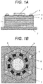
- FIGs. 1A and 1B are views showing a configuration of an iron core and a motor according to Embodiment 1 of the disclosure, specifically, a brushless motor.
- FIG. 1A is a side view of an iron core and a motor
- FIG. 1B is a top view.
- an iron core includes laminate 1 of nanocrystal thin strips 2 and a fastening mechanism composed of bolt 5 and fastener 6 penetrating laminate 1 and fastening them to metal board 7.
- the iron core to which winding 9 is applied is a stator.
- Rotor 8 is provided in an inner diameter portion of the stator, and the motor is driven by energizing.
- Laminate 1 is an iron core member of the stator of the motor. Laminate 1 becomes laminate 1 of nanocrystal thin strips 2 by laminating nanocrystal thin strips 2 which are amorphous alloy thin strips without using an adhesive therebetween and subjecting them to heat treatment. A space factor can be increased by not using an adhesive.
- the amorphous alloy thin strip before the heat treatment is an iron alloy having a plate thickness of 10 ⁇ m to 60 ⁇ m and containing at least one of boron and silicon.
- the amorphous alloy thin strip is manufactured by quenching by pouring the melted iron alloy onto a surface of a rotating cooling drum and stretching it into a ribbon shape.
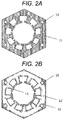
- a region of invisible oxide film 12 showing metallic luster may remain in a vicinity of the site.
- a region of visible oxide film 11 is wider than the region of invisible oxide film 12.
- Through-hole 10 is a through-hole for inserting bolt 5. Visible colors tend to obtain good magnetic characteristics in the range visible to bare eyes as shiny brown, blue, violet, and the like. However, there is no strict correlation between the color and magnetic characteristics.
- Nanocrystal thin strip 2 of FIG. 2B shows an interlayer surface of laminate 1. It has the region of invisible oxide film 12 showing metallic luster. Between the surfaces of nanocrystal thin strips 2, nanocrystal thin strips 2 come into contact with each other, or the gap between nanocrystal thin strips 2 becomes very narrow. Therefore, the atmosphere and the like can barely enter between the surfaces of nanocrystal thin strips 2. Therefore, as before the heat treatment, it is assumed that the region of invisible oxide film 12 showing metallic luster remains on the surface of nanocrystal thin strip 2.
- a visible, that is, a colored oxide film and an invisible, that is, an uncolored oxide film have almost the same thickness.
- the outer periphery of the region of invisible oxide film 12 showing metallic luster is surrounded by the region of visible oxide film 11. It is considered that this is the influence of the atmosphere entering through a small gap between the layers of nanocrystal thin strips 2 because the outer periphery of nanocrystal thin strip 2 is close. Even if laminated nanocrystal thin strips 2 are heat treated, if the number of the pieces is the upper limit or lower, each of nanocrystal thin strips 2 obtains predetermined magnetic characteristics. When the number of pieces exceeds the upper limit, the difference in temperature distribution in the thickness direction increases, and thereby good magnetic characteristics cannot be obtained.
- nanocrystal thin strips 2 on the surface of laminate 1 have mainly visible oxide film 11 on one side and mainly invisible oxide film 12 showing metallic luster on the other side.
- Nanocrystal thin strips 2 inside laminate 1 have mainly invisible oxide film 12 showing metallic luster on both sides.
- Single nanocrystal thin strip 2 of laminate 1 has mainly the visible oxide film on both sides.
- Nanocrystal thin strips 2 of laminate 1 may include any one of above-described nanocrystal thin strips 2.
- the heat generated by self-heating accompanied with crystallization is likely to be accumulated between laminated nanocrystal thin strips 2. Due to the excessive temperature rise, not only the magnetic characteristics are rather deteriorated, but also it becomes brittle and easily damaged. Although it depends on target magnetic characteristics and heat treatment conditions, good magnetic characteristics can be obtained even when ten or more nanocrystal thin strips 2 are laminated and heat treated.
- a portion of the region is pressed by fastener 6 and heat treated without using an adhesive between nanocrystal thin strips 2, so that the heat treatment can be performed in a laminated state, and characteristics can be obtained.
- processes such as heat treatment and lamination can be processed at once with ten or more pieces. Since the plate thickness of nanocrystal thin strip 2 is as thin as about one-tenth of an electromagnetic steel plate, there is a problem that the productivity deteriorates to about one-tenth when treated one by one. However, since ten or more pieces can be processed at once, this problem can be solved. Therefore, it is possible to manufacture laminate 1 of nanocrystal thin strips 2 with stable magnetic characteristics without impairing the productivity.
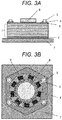
- FIGs. 3A and 3B are views showing configurations of an iron core and a motor according to Embodiment 2 of the disclosure.
- FIG. 3A is a side view of the iron core and motor
- FIG. 3B is a top view.
- FIGs. 3A and 3B are different from Embodiment 1 in that metal plate 4 is provided between laminate 1 in which nanocrystal thin strips 2 are laminated, and bolt 5 and fastener 6 which is a washer.
- nanocrystal thin strip 2 is brittle, when the same soft magnetic material electromagnetic steel plate is used for metal plate 4, nanocrystal thin strip 2 can be protected from the fastening force from bolt 5 and fastener 6, the tightening force of winding 9, or other external forces.
- metal plate 4 As another material for metal plate 4, as long as it is a nonmagnetic material, any materials not affecting the magnetic characteristics of the iron core can be used.
- metal plate 4 is provided above and below laminate 1, either one may be provided as long as the object can be achieved.
- metal plate 4 is provided on the surface thereof.
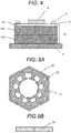
- FIG. 4 is a side view of an iron core and a motor according to Embodiment 3 of the disclosure.
- FIG. 4 is different from Embodiment 1 in that the entire laminated portion 20 has a three-stage structure in which same two first laminates 21a and 21b having a predetermined number of nanocrystal thin strips 2 and second laminate 22 having a smaller number of predetermined pieces are laminated.
- nanocrystal thin strips 2 are heat treated, it is difficult to secure temperature uniformity in the lamination direction when the number of laminated nanocrystal thin strips 2 increases, so that the width of the distribution of various magnetic characteristics increases between nanocrystal thin strips 2. Therefore, there is a limit in the laminated thickness of nanocrystal thin strips 2, and the heat treatment is performed for each laminate having a predetermined number of laminated pieces.
- laminated portion 20 is formed by laminating a plurality of laminates.
- the thickness of laminated portion 20 is thicker than a single laminate, one or plurality of laminates are laminated.
- the lamination amount of nanocrystal thin strip 2 in laminated portion 20 is controlled by the weight or the thickness at the time of fastening. Strictly speaking, since each nanocrystal thin strip 2 has different plate thicknesses, it is difficult to keep the thickness to be constant in controlling the number of laminated pieces.
- first, two first laminates 21a and 21b are laminated and the weight is measured. After confirming that the weight when another first laminate 21a or first laminate 21b is laminated exceeds a predetermined weight, second laminate 22 having less number of pieces than first laminate 21a and first laminate 21b is laminated to adjust the difference in weight. Since various values are generated in difference in weight, a plurality of laminates having different numbers of pieces or weights are prepared in advance, and second laminate 22 having an appropriate weight is laminated according to the difference in weight. In the case of thickness control, the difference in thickness can be adjusted similarly.
- Second laminate 22 having a smaller number of nanocrystal thin strips 2 than first laminate 21a, 21b having a larger number of nanocrystal thin strips 2 has a smaller number of pieces, so a more uniform heat treatment can be performed. Therefore, the magnetic characteristics are more stable. As a result, second laminate 22 not only can adjust the difference in weight and thickness but also stabilizes the magnetic characteristics.
- metal plate 4 may be provided between laminated portion 20 and a fastener including bolt 5 and fastener 6.
- FIG. 5A is a top view of first laminate 21 or second laminate 22, and FIG. 5B is a side view.
- Adhesive 23 is applied to the outer periphery of first laminate 21 and second laminate 22 and cured.
- An objective of providing adhesive 23 is to integrate first laminate 21 or second laminate 22 so that it can be easily handled. Therefore, as long as the integration can be secured, the bonding place may bond the entire outer periphery as shown in FIGs. 5A and 5B , partially bond the outer periphery, bond other inner portion such as a laminated end surface, or bond between layers of nanocrystal thin strip.
- the amorphous alloy thin strip may be bonded first to form first laminate 21 and second laminate 22, and then heat treatment may be performed, or nanocrystal thin strip 2 may be laminated and bonded.
- bonding between layers of the amorphous alloy thin strip causes disadvantages such as lowering the space factor, deteriorating heat conduction in the lamination direction during the heat treatment, increasing the width of distribution of the magnetic characteristics between nanocrystal thin strips 2, or requiring materials and time for interlayer bonding.
- adhesive 23 There is no particular restriction on the kind of adhesive 23. However, since it is often heated to 350°C or higher by the heat treatment, a polyimide-based adhesive with high heat resistance is desirable. When an adhesive with low heat resistance temperature such as an epoxy-based adhesive is used, the thermal history remains in the adhesive. A room temperature curing type or ultraviolet curing type adhesive may be used.
- FIG. 6A is a top view of a mechanically fastened laminate according to Embodiment 4 of the disclosure
- FIG. 6B is a cross-sectional view taken along line A-A' of FIG. 6A.
- FIGs. 6A and 6B are different from Embodiment 3 in that two portions are fixed by caulking member 24.
- the bonding causes disadvantages such as the magnetic characteristics being affected by other than the heat treatment due to the heating for curing or long treatment time for curing.
- mechanical means such as caulking
- the mechanical fastening method may be eyelets or a mechanism sandwiching the laminated end surface.
- FIG. 7 is a side view of an iron core and a motor according to Embodiment 5 of the disclosure.
- FIG. 7 is different from FIG. 4 of Embodiment 3 in that laminated portion 25 is formed by laminating two first laminates 21a and 21b having the same number of laminated nanocrystal thin strips 2 and layer 26 in which nanocrystal thin strips are laminated one by one instead of taking the form of a laminate in which nanocrystal thin strips 2 are fixed.
- the lamination amount of nanocrystal thin strips 2 in laminated portion 25 is controlled by the weight or the thickness at the time of fastening.
- first laminates 21a and 21b are laminated and the weight is measured first, and the difference in weight is adjusted by laminating nanocrystal thin strips 2 one by one. Therefore, the number of laminated layers 26 in which the nanocrystal thin strips are laminated is from one or more to less than the number of laminated layers of first laminates 21a and 21b.
- Nanocrystal thin strips 2 to be added may be heat treated one by one in separate process or may be taken one by one from first laminates 21a and 21b before the fixation and laminated. Nanocrystal thin strips 2 heat treated one by one are in a state having mainly visible oxide film 11 shown in FIG. 2A on both sides. There are two kinds of appearance of nanocrystal thin strip 2 in the case of extracting first laminates 21a and 21b before the fixation. One kind has one surface in a state shown in FIG. 2A and the other surface in a state having mainly invisible oxide film 12 showing metallic luster shown in FIG. 2B . Both sides are in the state of FIG. 2B in the other kind. Accordingly, layer 26 in which the nanocrystal thin strips are laminated, including any one kind or two or more kinds of these three kinds of nanocrystal thin strips is formed.
- metal plate 4 may be provided between laminated portion 25 and a fastener including bolt 5 and fastener 6.
- Embodiments 1 to 5 can be combined within the scope of the appended claim.
- the iron core according to the disclosure is useful as a stator of a motor. Furthermore, the iron core according to the disclosure can also be applied to applications of electronic components such as transformers, other than motors.
Landscapes
- Engineering & Computer Science (AREA)
- Power Engineering (AREA)
- Manufacturing & Machinery (AREA)
- Chemical & Material Sciences (AREA)
- Materials Engineering (AREA)
- Inorganic Chemistry (AREA)
- Crystallography & Structural Chemistry (AREA)
- Physics & Mathematics (AREA)
- Electromagnetism (AREA)
- Dispersion Chemistry (AREA)
- Iron Core Of Rotating Electric Machines (AREA)
- Manufacture Of Motors, Generators (AREA)
- Soft Magnetic Materials (AREA)
- Manufacturing Cores, Coils, And Magnets (AREA)
Description
- The technical field relates to a method to produce an iron core in which soft magnetic thin strips are laminated.
- As a laminate of magnetic plates in an iron core (stator) for a motor in the related art, pure iron or an electromagnetic steel plate is used. In motors aimed for higher efficiency, amorphous thin strips or thin strips having nanocrystal grains are used in some iron cores (for example, see
Japanese Patent Unexamined Publication No. 6-145917 - A manufacturing process of a stator core disclosed in
Japanese Patent Unexamined Publication No. 6-145917 - An alloy ribbon and a member using it is disclosed in
Japanese Patent Application Publication No. 2004-353090 European Patent Application Publication No. 2 958 116 . A bulk amorphous metal inductive device is disclosed in theUS Patent Application Publication No. 2004-0085173 . Finally, a selective etching process for cutting amorphous metal shapes and components made thereof is disclosed in theUS Patent Application Publication No. 2004-0212269 . - However, in order to make the amorphous alloy thin strip to be a nanocrystal thin strip which is supposed to have better soft magnetic characteristics, further heat treatment is required. Here, the thickness of the nanocrystal thin strip is about one-tenth of the thickness of a commonly used electromagnetic steel plate. Therefore, when the heat treatment is performed one by one, the handling amount is about ten times higher than the one in the related art.
- As a result, in the heat treatment and a subsequent lamination process, there is a problem that about ten times productivity for obtaining the same laminated thickness is required compared to the case of the electromagnetic steel plate.
- An object of the disclosure is to solve the problems in the related art, and to provide an iron core and a motor of nanocrystal thin strips with stable magnetic characteristics without impairing productivity.
- In order to achieve the above-described object, a method is defined in the appended claim and allows to obtain an iron core including a laminate in which a plurality of nanocrystal thin strips are laminated, a board, and a fastener that fastens the laminate and the board, in which at least one of upper and lower surfaces of the laminate has a colored oxide film and an uncolored oxide film is used. Moreover, the iron core having a region of the colored oxide film wider than a region of the uncolored oxide film region is used. Furthermore, a motor using the above-described iron core as a stator is used.
- According to the present method, since the nanocrystal thin strips obtained by performing heat treatment on the laminated amorphous alloy thin strips at once are laminated, it is possible to provide an iron core and a motor of nanocrystal thin strips with stable magnetic characteristics without impairing productivity.
- According to the present method, it is possible to provide an iron core and a motor of nanocrystal thin strips with stable magnetic characteristics without impairing productivity.
-
-
FIG. 1A is a side view of an iron core and a motor according toEmbodiment 1 of the disclosure; -
FIG. 1B is a top view ofFIG. 1A ; -
FIG. 2A is a view showing upper and lower surfaces of a laminate having mainly a visible oxide film according toEmbodiment 1 of the disclosure; -
FIG. 2B is a view showing an interlayer surface of a laminate having mainly an invisible oxide film according toEmbodiment 1 of the disclosure; -
FIG. 3A is a side view of an iron core and a motor according toEmbodiment 2 of the disclosure; -
FIG. 4 is a side view of an iron core and a motor according to Embodiment 3 of the disclosure; -
FIG. 5A is a top view of a bonded laminate according to Embodiment 3 of the disclosure; -
FIG. 5B is a side view ofFIG. 5A ; -
FIG. 6A is a top view of a mechanically fastened laminate according toEmbodiment 4 of the disclosure; -
FIG. 6B is a cross-sectional view taken along line A-A' ofFIG. 6A ; and -
FIG. 7 is a side view of an iron core and a motor according toEmbodiment 5 of the disclosure. - Hereinafter, embodiments of the disclosure will be described with reference to the drawings.
-
FIGs. 1A and 1B are views showing a configuration of an iron core and a motor according toEmbodiment 1 of the disclosure, specifically, a brushless motor.FIG. 1A is a side view of an iron core and a motor, andFIG. 1B is a top view. - As shown in
FIGs. 1A and 1B , an iron core includeslaminate 1 of nanocrystalthin strips 2 and a fastening mechanism composed ofbolt 5 and fastener 6 penetratinglaminate 1 and fastening them tometal board 7. The iron core to which winding 9 is applied is a stator.Rotor 8 is provided in an inner diameter portion of the stator, and the motor is driven by energizing. - Laminate 1 is an iron core member of the stator of the motor.
Laminate 1 becomeslaminate 1 of nanocrystalthin strips 2 by laminating nanocrystalthin strips 2 which are amorphous alloy thin strips without using an adhesive therebetween and subjecting them to heat treatment. A space factor can be increased by not using an adhesive. The amorphous alloy thin strip before the heat treatment is an iron alloy having a plate thickness of 10 µm to 60 µm and containing at least one of boron and silicon. The amorphous alloy thin strip is manufactured by quenching by pouring the melted iron alloy onto a surface of a rotating cooling drum and stretching it into a ribbon shape. - When amorphous alloy thin strips prepared to have a predetermined weight or laminated thickness are laminated and heat treated, a region having
visible oxide film 11 on almost the entire surface is obtained on at least one of upper and lower surfaces as shown in nanocrystalthin strip 2 ofFIG. 2A . - However, due to the influence of components fixing the laminate, a region of
invisible oxide film 12 showing metallic luster may remain in a vicinity of the site. A region ofvisible oxide film 11 is wider than the region ofinvisible oxide film 12. - Through-
hole 10 is a through-hole for insertingbolt 5. Visible colors tend to obtain good magnetic characteristics in the range visible to bare eyes as shiny brown, blue, violet, and the like. However, there is no strict correlation between the color and magnetic characteristics. - Nanocrystal
thin strip 2 ofFIG. 2B shows an interlayer surface oflaminate 1. It has the region ofinvisible oxide film 12 showing metallic luster. Between the surfaces of nanocrystalthin strips 2, nanocrystalthin strips 2 come into contact with each other, or the gap between nanocrystalthin strips 2 becomes very narrow. Therefore, the atmosphere and the like can barely enter between the surfaces of nanocrystalthin strips 2. Therefore, as before the heat treatment, it is assumed that the region ofinvisible oxide film 12 showing metallic luster remains on the surface of nanocrystalthin strip 2. - "Visible" indicates that it is colored, which means that it is not metallic luster, white, black, or transparent. "Invisible" indicates that the above-mentioned coloring is not carried out.
- Regarding the film thickness of the formed oxide film, a visible, that is, a colored oxide film and an invisible, that is, an uncolored oxide film have almost the same thickness.
- In principle, a normal healthy person can know with bare eyes whether the oxide film is colored or not.
- The outer periphery of the region of
invisible oxide film 12 showing metallic luster is surrounded by the region ofvisible oxide film 11. It is considered that this is the influence of the atmosphere entering through a small gap between the layers of nanocrystalthin strips 2 because the outer periphery of nanocrystalthin strip 2 is close. Even if laminated nanocrystalthin strips 2 are heat treated, if the number of the pieces is the upper limit or lower, each of nanocrystalthin strips 2 obtains predetermined magnetic characteristics. When the number of pieces exceeds the upper limit, the difference in temperature distribution in the thickness direction increases, and thereby good magnetic characteristics cannot be obtained. - Accordingly, nanocrystal
thin strips 2 on the surface oflaminate 1 have mainlyvisible oxide film 11 on one side and mainlyinvisible oxide film 12 showing metallic luster on the other side. - Nanocrystal
thin strips 2 insidelaminate 1 have mainlyinvisible oxide film 12 showing metallic luster on both sides. - Single nanocrystal
thin strip 2 oflaminate 1 has mainly the visible oxide film on both sides. - Nanocrystal
thin strips 2 oflaminate 1 may include any one of above-described nanocrystalthin strips 2. - The heat generated by self-heating accompanied with crystallization is likely to be accumulated between laminated nanocrystal
thin strips 2. Due to the excessive temperature rise, not only the magnetic characteristics are rather deteriorated, but also it becomes brittle and easily damaged. Although it depends on target magnetic characteristics and heat treatment conditions, good magnetic characteristics can be obtained even when ten or more nanocrystalthin strips 2 are laminated and heat treated. - A portion of the region is pressed by
fastener 6 and heat treated without using an adhesive between nanocrystalthin strips 2, so that the heat treatment can be performed in a laminated state, and characteristics can be obtained. - Accordingly, processes such as heat treatment and lamination can be processed at once with ten or more pieces. Since the plate thickness of nanocrystal
thin strip 2 is as thin as about one-tenth of an electromagnetic steel plate, there is a problem that the productivity deteriorates to about one-tenth when treated one by one. However, since ten or more pieces can be processed at once, this problem can be solved. Therefore, it is possible to manufacturelaminate 1 of nanocrystalthin strips 2 with stable magnetic characteristics without impairing the productivity. -
FIGs. 3A and 3B are views showing configurations of an iron core and a motor according toEmbodiment 2 of the disclosure.FIG. 3A is a side view of the iron core and motor, andFIG. 3B is a top view.FIGs. 3A and 3B are different fromEmbodiment 1 in thatmetal plate 4 is provided betweenlaminate 1 in which nanocrystalthin strips 2 are laminated, andbolt 5 andfastener 6 which is a washer. - Since nanocrystal
thin strip 2 is brittle, when the same soft magnetic material electromagnetic steel plate is used formetal plate 4, nanocrystalthin strip 2 can be protected from the fastening force frombolt 5 andfastener 6, the tightening force of winding 9, or other external forces. - As another material for
metal plate 4, as long as it is a nonmagnetic material, any materials not affecting the magnetic characteristics of the iron core can be used. InFIGs. 3A and 3B , althoughmetal plate 4 is provided above and belowlaminate 1, either one may be provided as long as the object can be achieved. - In a case where one or a plurality of nanocrystal
thin strips 2 are used instead oflaminate 1,metal plate 4 is provided on the surface thereof. -
FIG. 4 is a side view of an iron core and a motor according to Embodiment 3 of the disclosure.FIG. 4 is different fromEmbodiment 1 in that the entirelaminated portion 20 has a three-stage structure in which same twofirst laminates thin strips 2 andsecond laminate 22 having a smaller number of predetermined pieces are laminated. - When nanocrystal
thin strips 2 are heat treated, it is difficult to secure temperature uniformity in the lamination direction when the number of laminated nanocrystalthin strips 2 increases, so that the width of the distribution of various magnetic characteristics increases between nanocrystalthin strips 2. Therefore, there is a limit in the laminated thickness of nanocrystalthin strips 2, and the heat treatment is performed for each laminate having a predetermined number of laminated pieces. - Therefore,
laminated portion 20 is formed by laminating a plurality of laminates. - In a case where the thickness of
laminated portion 20 is thicker than a single laminate, one or plurality of laminates are laminated. The lamination amount of nanocrystalthin strip 2 inlaminated portion 20 is controlled by the weight or the thickness at the time of fastening. Strictly speaking, since each nanocrystalthin strip 2 has different plate thicknesses, it is difficult to keep the thickness to be constant in controlling the number of laminated pieces. - In
FIG. 4 , first, twofirst laminates first laminate 21a orfirst laminate 21b is laminated exceeds a predetermined weight,second laminate 22 having less number of pieces thanfirst laminate 21a andfirst laminate 21b is laminated to adjust the difference in weight. Since various values are generated in difference in weight, a plurality of laminates having different numbers of pieces or weights are prepared in advance, andsecond laminate 22 having an appropriate weight is laminated according to the difference in weight. In the case of thickness control, the difference in thickness can be adjusted similarly. -
Second laminate 22 having a smaller number of nanocrystalthin strips 2 thanfirst laminate thin strips 2 has a smaller number of pieces, so a more uniform heat treatment can be performed. Therefore, the magnetic characteristics are more stable. As a result,second laminate 22 not only can adjust the difference in weight and thickness but also stabilizes the magnetic characteristics. - As in
FIGs. 3A and 3B ,metal plate 4 may be provided betweenlaminated portion 20 and afastener including bolt 5 andfastener 6. -
FIG. 5A is a top view of first laminate 21 orsecond laminate 22, andFIG. 5B is a side view.Adhesive 23 is applied to the outer periphery of first laminate 21 andsecond laminate 22 and cured. An objective of providingadhesive 23 is to integrate first laminate 21 orsecond laminate 22 so that it can be easily handled. Therefore, as long as the integration can be secured, the bonding place may bond the entire outer periphery as shown inFIGs. 5A and 5B , partially bond the outer periphery, bond other inner portion such as a laminated end surface, or bond between layers of nanocrystal thin strip. The amorphous alloy thin strip may be bonded first to form first laminate 21 andsecond laminate 22, and then heat treatment may be performed, or nanocrystalthin strip 2 may be laminated and bonded. - However, bonding between layers of the amorphous alloy thin strip causes disadvantages such as lowering the space factor, deteriorating heat conduction in the lamination direction during the heat treatment, increasing the width of distribution of the magnetic characteristics between nanocrystal
thin strips 2, or requiring materials and time for interlayer bonding. - There is no particular restriction on the kind of
adhesive 23. However, since it is often heated to 350°C or higher by the heat treatment, a polyimide-based adhesive with high heat resistance is desirable. When an adhesive with low heat resistance temperature such as an epoxy-based adhesive is used, the thermal history remains in the adhesive. A room temperature curing type or ultraviolet curing type adhesive may be used. -
FIG. 6A is a top view of a mechanically fastened laminate according toEmbodiment 4 of the disclosure, andFIG. 6B is a cross-sectional view taken along line A-A' ofFIG. 6A. FIGs. 6A and 6B are different from Embodiment 3 in that two portions are fixed bycaulking member 24. The bonding causes disadvantages such as the magnetic characteristics being affected by other than the heat treatment due to the heating for curing or long treatment time for curing. However, when mechanical means such as caulking is used, there is an advantage that it can be fixed in a short time of crushing at room temperature. Besides caulking, the mechanical fastening method may be eyelets or a mechanism sandwiching the laminated end surface. -
FIG. 7 is a side view of an iron core and a motor according toEmbodiment 5 of the disclosure.FIG. 7 is different fromFIG. 4 of Embodiment 3 in thatlaminated portion 25 is formed by laminating twofirst laminates thin strips 2 andlayer 26 in which nanocrystal thin strips are laminated one by one instead of taking the form of a laminate in which nanocrystalthin strips 2 are fixed. - As described in
FIG. 4 , the lamination amount of nanocrystalthin strips 2 inlaminated portion 25 is controlled by the weight or the thickness at the time of fastening. InFIG. 7 as well,first laminates thin strips 2 one by one. Therefore, the number oflaminated layers 26 in which the nanocrystal thin strips are laminated is from one or more to less than the number of laminated layers offirst laminates - However, in a case where the plate thickness is thin, the number of pieces may be larger than
first laminates thin strips 2 to be added may be heat treated one by one in separate process or may be taken one by one fromfirst laminates thin strips 2 heat treated one by one are in a state having mainlyvisible oxide film 11 shown inFIG. 2A on both sides. There are two kinds of appearance of nanocrystalthin strip 2 in the case of extractingfirst laminates FIG. 2A and the other surface in a state having mainlyinvisible oxide film 12 showing metallic luster shown inFIG. 2B . Both sides are in the state ofFIG. 2B in the other kind. Accordingly,layer 26 in which the nanocrystal thin strips are laminated, including any one kind or two or more kinds of these three kinds of nanocrystal thin strips is formed. - As in
FIGs. 3A and 3B ,metal plate 4 may be provided betweenlaminated portion 25 and afastener including bolt 5 andfastener 6. - As a whole,
Embodiments 1 to 5 can be combined within the scope of the appended claim. - The iron core according to the disclosure is useful as a stator of a motor. Furthermore, the iron core according to the disclosure can also be applied to applications of electronic components such as transformers, other than motors.
-
- 1 LAMINATE
- 2 NANOCRYSTAL THIN STRIP
- 4 METAL PLATE
- 5 BOLT
- 6 FASTENER
- 7 METAL BOARD
- 8 ROTOR
- 9 WINDING
- 10 THROUGH-HOLE
- 11 VISIBLE OXIDE FILM
- 12 INVISIBLE OXIDE FILM
- 20 LAMINATED PORTION
- 21a,21b FIRST LAMINATE
- 22 SECOND LAMINATE
- 23 ADHESIVE
- 24 CAULKING MEMBER
- 25 LAMINATED PORTION
- 26 LAMINATED LAYER IN WHICH NANOCRYSTAL THIN STRIPS ARE LAMINATED
Claims (1)
- A method to produce an iron core comprising a laminate (1), the method comprising the steps of:- laminating a plurality of amorphous alloy thin strips without using an adhesive;- fastening the laminate on a metal board with a fastener comprising bolt (5) and fastener (6) penetrating the laminate (1);- subjecting the laminate (1) to heat treatment to obtain a laminate (1) in which a plurality of nanocrystal thin strips (2) is laminated and in which at least one of upper and lower surfaces of the laminate has a colored oxide film (11) and an uncolored oxide film (12);wherein the amorphous thin strips before heat treatment are made of iron alloy having a plate thickness of 10 µm to 60 µm and containing at least one of boron and silicon.
Applications Claiming Priority (2)
| Application Number | Priority Date | Filing Date | Title |
|---|---|---|---|
| JP2016237248 | 2016-12-07 | ||
| PCT/JP2017/042978 WO2018105473A1 (en) | 2016-12-07 | 2017-11-30 | Iron core and motor |
Publications (3)
| Publication Number | Publication Date |
|---|---|
| EP3553799A1 EP3553799A1 (en) | 2019-10-16 |
| EP3553799A4 EP3553799A4 (en) | 2019-11-20 |
| EP3553799B1 true EP3553799B1 (en) | 2021-07-14 |
Family
ID=62491891
Family Applications (1)
| Application Number | Title | Priority Date | Filing Date |
|---|---|---|---|
| EP17877845.2A Active EP3553799B1 (en) | 2016-12-07 | 2017-11-30 | Method to produce an iron core |
Country Status (5)
| Country | Link |
|---|---|
| US (1) | US11025103B2 (en) |
| EP (1) | EP3553799B1 (en) |
| JP (1) | JP6490313B2 (en) |
| CN (1) | CN109643603B (en) |
| WO (1) | WO2018105473A1 (en) |
Families Citing this family (23)
| Publication number | Priority date | Publication date | Assignee | Title |
|---|---|---|---|---|
| WO2020042912A1 (en) * | 2018-08-31 | 2020-03-05 | 浙江盘毂动力科技有限公司 | Segment core and axial flux motor |
| WO2020100527A1 (en) * | 2018-11-16 | 2020-05-22 | パナソニックIpマネジメント株式会社 | Motor, compressor, and motor manufacturing method |
| CA3131540A1 (en) | 2018-12-17 | 2020-06-25 | Nippon Steel Corporation | Laminated core and electric motor |
| EP3902106B1 (en) | 2018-12-17 | 2025-10-29 | Nippon Steel Corporation | Adhesively laminated core for stator, method of manufacturing the same, and electric motor |
| PL3902123T3 (en) | 2018-12-17 | 2026-02-09 | Nippon Steel Corporation | Laminated core, laminated core manufacturing method, and electric motor |
| SG11202108986QA (en) | 2018-12-17 | 2021-09-29 | Nippon Steel Corp | Laminated core and electric motor |
| WO2020129936A1 (en) | 2018-12-17 | 2020-06-25 | 日本製鉄株式会社 | Stacked core and rotary electric machine |
| EA202192064A1 (en) | 2018-12-17 | 2021-11-24 | Ниппон Стил Корпорейшн | CORE AND ELECTRIC MOTOR |
| US12261482B2 (en) | 2018-12-17 | 2025-03-25 | Nippon Steel Corporation | Laminated core and electric motor |
| CN113243073B (en) | 2018-12-17 | 2024-08-16 | 日本制铁株式会社 | Laminated iron core and rotary electric machine |
| EA202192071A1 (en) | 2018-12-17 | 2021-11-08 | Ниппон Стил Корпорейшн | CORE AND ELECTRIC MOTOR |
| SG11202108950YA (en) | 2018-12-17 | 2021-09-29 | Nippon Steel Corp | Adhesively-laminated core for stator and electric motor |
| US11863017B2 (en) | 2018-12-17 | 2024-01-02 | Nippon Steel Corporation | Laminated core and electric motor |
| WO2020129946A1 (en) | 2018-12-17 | 2020-06-25 | 日本製鉄株式会社 | Glue lamination core for stators and method for manufacturing same, and rotating electrical machine |
| CN113169595B (en) | 2018-12-17 | 2025-02-28 | 日本制铁株式会社 | Laminated iron core, iron core block, rotating electrical machine and method for manufacturing iron core block |
| PL3902121T3 (en) | 2018-12-17 | 2025-11-24 | Nippon Steel Corporation | Adhesively laminated core for stator and electric motor |
| JP7180690B2 (en) | 2018-12-17 | 2022-11-30 | 日本製鉄株式会社 | LAMINATED CORE, MANUFACTURING METHOD THEREOF, AND ROTATING ELECTRICAL MACHINE |
| EA202192070A1 (en) | 2018-12-17 | 2021-11-08 | Ниппон Стил Корпорейшн | GLUED-PLATED CORE FOR STATOR, METHOD OF ITS PRODUCTION AND ELECTRIC MOTOR |
| CN113196616B (en) | 2018-12-17 | 2024-03-29 | 日本制铁株式会社 | Laminated iron core and rotary electric machine |
| JP7095654B2 (en) * | 2019-05-23 | 2022-07-05 | トヨタ自動車株式会社 | Metal leaf manufacturing method |
| EP4191618B1 (en) | 2020-09-09 | 2026-01-07 | Delta Electronics (Japan), Inc. | Magnetic core and magnetic part |
| JPWO2022054722A1 (en) * | 2020-09-09 | 2022-03-17 | ||
| JP7590846B2 (en) * | 2020-10-02 | 2024-11-27 | 東芝産業機器システム株式会社 | Manufacturing system and method for laminated core |
Family Cites Families (22)
| Publication number | Priority date | Publication date | Assignee | Title |
|---|---|---|---|---|
| JPS61205241U (en) * | 1985-06-14 | 1986-12-24 | ||
| JPH06145917A (en) | 1992-11-09 | 1994-05-27 | Hitachi Metals Ltd | Motor |
| JP2668636B2 (en) | 1993-06-29 | 1997-10-27 | 株式会社三協精機製作所 | motor |
| KR100240995B1 (en) | 1995-12-19 | 2000-03-02 | 이구택 | Manufacturing method of non-oriented electrical steel sheet having excellent adhesion of insulating film |
| US5929545A (en) * | 1997-11-26 | 1999-07-27 | Emerson Electric Co. | End shield for an electric motor, electric motor construction, and method of assembling electric motor |
| FR2788455B1 (en) * | 1999-01-19 | 2001-04-06 | Imphy Ugine Precision | PROCESS FOR TREATING A FRAGILE METAL THIN STRIP AND MAGNETIC PARTS MADE FROM A NANOCRYSTALLINE ALLOY STRIP |
| JP2004353090A (en) * | 1999-04-15 | 2004-12-16 | Hitachi Metals Ltd | Amorphous alloy ribbon and member using the same |
| EP1045402B1 (en) | 1999-04-15 | 2011-08-31 | Hitachi Metals, Ltd. | Soft magnetic alloy strip, manufacturing method and use thereof |
| US6562473B1 (en) * | 1999-12-03 | 2003-05-13 | Kawasaki Steel Corporation | Electrical steel sheet suitable for compact iron core and manufacturing method therefor |
| US6737951B1 (en) * | 2002-11-01 | 2004-05-18 | Metglas, Inc. | Bulk amorphous metal inductive device |
| US7235910B2 (en) * | 2003-04-25 | 2007-06-26 | Metglas, Inc. | Selective etching process for cutting amorphous metal shapes and components made thereof |
| JP2005103874A (en) * | 2003-09-30 | 2005-04-21 | Kawaguchiko Seimitsu Co Ltd | Decorative component, its manufacturing method and electronic equipment with decorative component |
| WO2008133026A1 (en) * | 2007-04-13 | 2008-11-06 | Hitachi Metals, Ltd. | Magnetic core for antenna, method for producing magnetic core for antenna, and antenna |
| ES2616345T3 (en) * | 2007-04-25 | 2017-06-12 | Hitachi Metals, Ltd. | Soft magnetic thin band, process for its production, magnetic pieces, and thin amorphous band |
| JP4648504B2 (en) * | 2009-03-26 | 2011-03-09 | リンテック株式会社 | Method for forming metal oxide film and metal oxide film |
| JP6181346B2 (en) * | 2010-03-23 | 2017-08-16 | 株式会社トーキン | Alloy composition, Fe-based nanocrystalline alloy and method for producing the same, and magnetic component |
| CN102868241A (en) * | 2012-09-20 | 2013-01-09 | 安泰科技股份有限公司 | Stator core and manufacturing method thereof |
| JP6075438B2 (en) * | 2013-02-15 | 2017-02-08 | 日立金属株式会社 | Annular magnetic core using Fe-based nanocrystalline soft magnetic alloy, and magnetic component using the same |
| JP6191908B2 (en) * | 2013-06-12 | 2017-09-06 | 日立金属株式会社 | Nanocrystalline soft magnetic alloy and magnetic component using the same |
| JP6444504B2 (en) * | 2015-07-03 | 2018-12-26 | 株式会社東北マグネットインスティテュート | Laminated magnetic core and manufacturing method thereof |
| JP6517844B2 (en) * | 2016-02-09 | 2019-05-22 | 株式会社東北マグネットインスティテュート | Heat treatment apparatus and soft magnetic core for laminate of amorphous alloy ribbon |
| CN105821369A (en) * | 2016-05-17 | 2016-08-03 | 山东大学 | Method for preparing titanium oxide micro-nano crystals on surface of titanium alloy |
-
2017
- 2017-11-30 EP EP17877845.2A patent/EP3553799B1/en active Active
- 2017-11-30 WO PCT/JP2017/042978 patent/WO2018105473A1/en not_active Ceased
- 2017-11-30 CN CN201780051502.9A patent/CN109643603B/en not_active Expired - Fee Related
- 2017-11-30 JP JP2018541376A patent/JP6490313B2/en not_active Expired - Fee Related
-
2019
- 2019-02-05 US US16/268,439 patent/US11025103B2/en not_active Expired - Fee Related
Non-Patent Citations (1)
| Title |
|---|
| None * |
Also Published As
| Publication number | Publication date |
|---|---|
| US11025103B2 (en) | 2021-06-01 |
| EP3553799A1 (en) | 2019-10-16 |
| WO2018105473A1 (en) | 2018-06-14 |
| EP3553799A4 (en) | 2019-11-20 |
| CN109643603B (en) | 2021-04-13 |
| JP6490313B2 (en) | 2019-03-27 |
| JPWO2018105473A1 (en) | 2018-12-20 |
| US20190173328A1 (en) | 2019-06-06 |
| CN109643603A (en) | 2019-04-16 |
Similar Documents
| Publication | Publication Date | Title |
|---|---|---|
| EP3553799B1 (en) | Method to produce an iron core | |
| CZ20012582A3 (en) | Method enabling treatment of at least one thin metal strip, notably for subsequent production of components for magnetic applications from nanocrystalline alloy strip | |
| KR101057464B1 (en) | Amorphous metal magnetic element for electric motors with low core loss | |
| EP3902121B1 (en) | Adhesively laminated core for stator and electric motor | |
| US11594356B2 (en) | Magnetic field shielding sheet, method for manufacturing magnetic field shielding sheet, and antenna module using same | |
| EP1764424B1 (en) | Magnetic substrate, laminate of magnetic substrate and method for producing thereof | |
| US10636567B2 (en) | Heat treatment apparatus for laminated body of amorphous alloy ribbon and soft magnetic core | |
| CN102782185B (en) | Non-oriented electrical steel sheet and manufacturing method thereof | |
| JP6522252B2 (en) | THIN-LIP PARTS, ITS MANUFACTURING METHOD, AND MOTOR USING THIN-LIP PARTS | |
| JP2009533855A (en) | Lamination method of electromagnetic steel strip for transformer core | |
| JP2008213410A (en) | Laminated sheet and manufacturing method of laminate | |
| EP3340435A1 (en) | Stator core and motor equipped with same | |
| US10461589B2 (en) | Magnetic-plate laminated body and motor | |
| WO2018155206A1 (en) | Laminated member, method for manufacturing same, laminated body, and motor | |
| JP7645026B2 (en) | Method for manufacturing laminate of iron-based amorphous alloy | |
| EP3035351B1 (en) | Method of manufacturing an amorphous magnetic core and amorphous magnetic core | |
| JP2019145704A (en) | Laminate of soft magnetic ribbon | |
| EP3247027B1 (en) | Method of manufacturing a lamination stack for use in an electrical machine | |
| JPS63115313A (en) | Manufacture of core using amorphous magnetic alloy thin strip laminated plate | |
| JPS6298709A (en) | Manufacturing method for electromagnetic induction equipment core |
Legal Events
| Date | Code | Title | Description |
|---|---|---|---|
| STAA | Information on the status of an ep patent application or granted ep patent |
Free format text: STATUS: THE INTERNATIONAL PUBLICATION HAS BEEN MADE |
|
| PUAI | Public reference made under article 153(3) epc to a published international application that has entered the european phase |
Free format text: ORIGINAL CODE: 0009012 |
|
| STAA | Information on the status of an ep patent application or granted ep patent |
Free format text: STATUS: REQUEST FOR EXAMINATION WAS MADE |
|
| REG | Reference to a national code |
Ref country code: DE Ref legal event code: R079 Ref document number: 602017042301 Country of ref document: DE Free format text: PREVIOUS MAIN CLASS: H01F0027245000 Ipc: H01F0001153000 |
|
| 17P | Request for examination filed |
Effective date: 20190219 |
|
| AK | Designated contracting states |
Kind code of ref document: A1 Designated state(s): AL AT BE BG CH CY CZ DE DK EE ES FI FR GB GR HR HU IE IS IT LI LT LU LV MC MK MT NL NO PL PT RO RS SE SI SK SM TR |
|
| AX | Request for extension of the european patent |
Extension state: BA ME |
|
| A4 | Supplementary search report drawn up and despatched |
Effective date: 20191018 |
|
| RIC1 | Information provided on ipc code assigned before grant |
Ipc: H01F 1/153 20060101AFI20191014BHEP Ipc: H01F 41/02 20060101ALI20191014BHEP Ipc: H02K 15/02 20060101ALI20191014BHEP Ipc: H02K 1/14 20060101ALI20191014BHEP Ipc: H02K 1/02 20060101ALI20191014BHEP Ipc: H01F 3/04 20060101ALI20191014BHEP |
|
| DAV | Request for validation of the european patent (deleted) | ||
| DAX | Request for extension of the european patent (deleted) | ||
| GRAP | Despatch of communication of intention to grant a patent |
Free format text: ORIGINAL CODE: EPIDOSNIGR1 |
|
| STAA | Information on the status of an ep patent application or granted ep patent |
Free format text: STATUS: GRANT OF PATENT IS INTENDED |
|
| INTG | Intention to grant announced |
Effective date: 20210316 |
|
| GRAS | Grant fee paid |
Free format text: ORIGINAL CODE: EPIDOSNIGR3 |
|
| GRAA | (expected) grant |
Free format text: ORIGINAL CODE: 0009210 |
|
| STAA | Information on the status of an ep patent application or granted ep patent |
Free format text: STATUS: THE PATENT HAS BEEN GRANTED |
|
| AK | Designated contracting states |
Kind code of ref document: B1 Designated state(s): AL AT BE BG CH CY CZ DE DK EE ES FI FR GB GR HR HU IE IS IT LI LT LU LV MC MK MT NL NO PL PT RO RS SE SI SK SM TR |
|
| REG | Reference to a national code |
Ref country code: GB Ref legal event code: FG4D |
|
| REG | Reference to a national code |
Ref country code: DE Ref legal event code: R096 Ref document number: 602017042301 Country of ref document: DE |
|
| REG | Reference to a national code |
Ref country code: IE Ref legal event code: FG4D |
|
| REG | Reference to a national code |
Ref country code: AT Ref legal event code: REF Ref document number: 1411300 Country of ref document: AT Kind code of ref document: T Effective date: 20210815 |
|
| REG | Reference to a national code |
Ref country code: LT Ref legal event code: MG9D |
|
| REG | Reference to a national code |
Ref country code: NL Ref legal event code: MP Effective date: 20210714 |
|
| REG | Reference to a national code |
Ref country code: AT Ref legal event code: MK05 Ref document number: 1411300 Country of ref document: AT Kind code of ref document: T Effective date: 20210714 |
|
| PG25 | Lapsed in a contracting state [announced via postgrant information from national office to epo] |
Ref country code: RS Free format text: LAPSE BECAUSE OF FAILURE TO SUBMIT A TRANSLATION OF THE DESCRIPTION OR TO PAY THE FEE WITHIN THE PRESCRIBED TIME-LIMIT Effective date: 20210714 Ref country code: SE Free format text: LAPSE BECAUSE OF FAILURE TO SUBMIT A TRANSLATION OF THE DESCRIPTION OR TO PAY THE FEE WITHIN THE PRESCRIBED TIME-LIMIT Effective date: 20210714 Ref country code: HR Free format text: LAPSE BECAUSE OF FAILURE TO SUBMIT A TRANSLATION OF THE DESCRIPTION OR TO PAY THE FEE WITHIN THE PRESCRIBED TIME-LIMIT Effective date: 20210714 Ref country code: FI Free format text: LAPSE BECAUSE OF FAILURE TO SUBMIT A TRANSLATION OF THE DESCRIPTION OR TO PAY THE FEE WITHIN THE PRESCRIBED TIME-LIMIT Effective date: 20210714 Ref country code: ES Free format text: LAPSE BECAUSE OF FAILURE TO SUBMIT A TRANSLATION OF THE DESCRIPTION OR TO PAY THE FEE WITHIN THE PRESCRIBED TIME-LIMIT Effective date: 20210714 Ref country code: LT Free format text: LAPSE BECAUSE OF FAILURE TO SUBMIT A TRANSLATION OF THE DESCRIPTION OR TO PAY THE FEE WITHIN THE PRESCRIBED TIME-LIMIT Effective date: 20210714 Ref country code: AT Free format text: LAPSE BECAUSE OF FAILURE TO SUBMIT A TRANSLATION OF THE DESCRIPTION OR TO PAY THE FEE WITHIN THE PRESCRIBED TIME-LIMIT Effective date: 20210714 Ref country code: BG Free format text: LAPSE BECAUSE OF FAILURE TO SUBMIT A TRANSLATION OF THE DESCRIPTION OR TO PAY THE FEE WITHIN THE PRESCRIBED TIME-LIMIT Effective date: 20211014 Ref country code: NL Free format text: LAPSE BECAUSE OF FAILURE TO SUBMIT A TRANSLATION OF THE DESCRIPTION OR TO PAY THE FEE WITHIN THE PRESCRIBED TIME-LIMIT Effective date: 20210714 Ref country code: PT Free format text: LAPSE BECAUSE OF FAILURE TO SUBMIT A TRANSLATION OF THE DESCRIPTION OR TO PAY THE FEE WITHIN THE PRESCRIBED TIME-LIMIT Effective date: 20211115 Ref country code: NO Free format text: LAPSE BECAUSE OF FAILURE TO SUBMIT A TRANSLATION OF THE DESCRIPTION OR TO PAY THE FEE WITHIN THE PRESCRIBED TIME-LIMIT Effective date: 20211014 |
|
| PG25 | Lapsed in a contracting state [announced via postgrant information from national office to epo] |
Ref country code: PL Free format text: LAPSE BECAUSE OF FAILURE TO SUBMIT A TRANSLATION OF THE DESCRIPTION OR TO PAY THE FEE WITHIN THE PRESCRIBED TIME-LIMIT Effective date: 20210714 Ref country code: LV Free format text: LAPSE BECAUSE OF FAILURE TO SUBMIT A TRANSLATION OF THE DESCRIPTION OR TO PAY THE FEE WITHIN THE PRESCRIBED TIME-LIMIT Effective date: 20210714 Ref country code: GR Free format text: LAPSE BECAUSE OF FAILURE TO SUBMIT A TRANSLATION OF THE DESCRIPTION OR TO PAY THE FEE WITHIN THE PRESCRIBED TIME-LIMIT Effective date: 20211015 |
|
| REG | Reference to a national code |
Ref country code: DE Ref legal event code: R097 Ref document number: 602017042301 Country of ref document: DE |
|
| PG25 | Lapsed in a contracting state [announced via postgrant information from national office to epo] |
Ref country code: DK Free format text: LAPSE BECAUSE OF FAILURE TO SUBMIT A TRANSLATION OF THE DESCRIPTION OR TO PAY THE FEE WITHIN THE PRESCRIBED TIME-LIMIT Effective date: 20210714 |
|
| PLBE | No opposition filed within time limit |
Free format text: ORIGINAL CODE: 0009261 |
|
| STAA | Information on the status of an ep patent application or granted ep patent |
Free format text: STATUS: NO OPPOSITION FILED WITHIN TIME LIMIT |
|
| PG25 | Lapsed in a contracting state [announced via postgrant information from national office to epo] |
Ref country code: SM Free format text: LAPSE BECAUSE OF FAILURE TO SUBMIT A TRANSLATION OF THE DESCRIPTION OR TO PAY THE FEE WITHIN THE PRESCRIBED TIME-LIMIT Effective date: 20210714 Ref country code: SK Free format text: LAPSE BECAUSE OF FAILURE TO SUBMIT A TRANSLATION OF THE DESCRIPTION OR TO PAY THE FEE WITHIN THE PRESCRIBED TIME-LIMIT Effective date: 20210714 Ref country code: RO Free format text: LAPSE BECAUSE OF FAILURE TO SUBMIT A TRANSLATION OF THE DESCRIPTION OR TO PAY THE FEE WITHIN THE PRESCRIBED TIME-LIMIT Effective date: 20210714 Ref country code: EE Free format text: LAPSE BECAUSE OF FAILURE TO SUBMIT A TRANSLATION OF THE DESCRIPTION OR TO PAY THE FEE WITHIN THE PRESCRIBED TIME-LIMIT Effective date: 20210714 Ref country code: CZ Free format text: LAPSE BECAUSE OF FAILURE TO SUBMIT A TRANSLATION OF THE DESCRIPTION OR TO PAY THE FEE WITHIN THE PRESCRIBED TIME-LIMIT Effective date: 20210714 Ref country code: AL Free format text: LAPSE BECAUSE OF FAILURE TO SUBMIT A TRANSLATION OF THE DESCRIPTION OR TO PAY THE FEE WITHIN THE PRESCRIBED TIME-LIMIT Effective date: 20210714 |
|
| RAP4 | Party data changed (patent owner data changed or rights of a patent transferred) |
Owner name: PANASONIC HOLDINGS CORPORATION |
|
| 26N | No opposition filed |
Effective date: 20220419 |
|
| PG25 | Lapsed in a contracting state [announced via postgrant information from national office to epo] |
Ref country code: MC Free format text: LAPSE BECAUSE OF FAILURE TO SUBMIT A TRANSLATION OF THE DESCRIPTION OR TO PAY THE FEE WITHIN THE PRESCRIBED TIME-LIMIT Effective date: 20210714 |
|
| REG | Reference to a national code |
Ref country code: CH Ref legal event code: PL |
|
| PG25 | Lapsed in a contracting state [announced via postgrant information from national office to epo] |
Ref country code: LU Free format text: LAPSE BECAUSE OF NON-PAYMENT OF DUE FEES Effective date: 20211130 Ref country code: IT Free format text: LAPSE BECAUSE OF FAILURE TO SUBMIT A TRANSLATION OF THE DESCRIPTION OR TO PAY THE FEE WITHIN THE PRESCRIBED TIME-LIMIT Effective date: 20210714 Ref country code: BE Free format text: LAPSE BECAUSE OF NON-PAYMENT OF DUE FEES Effective date: 20211130 |
|
| REG | Reference to a national code |
Ref country code: BE Ref legal event code: MM Effective date: 20211130 |
|
| PG25 | Lapsed in a contracting state [announced via postgrant information from national office to epo] |
Ref country code: CH Free format text: LAPSE BECAUSE OF NON-PAYMENT OF DUE FEES Effective date: 20211130 Ref country code: LI Free format text: LAPSE BECAUSE OF NON-PAYMENT OF DUE FEES Effective date: 20211130 |
|
| PG25 | Lapsed in a contracting state [announced via postgrant information from national office to epo] |
Ref country code: IE Free format text: LAPSE BECAUSE OF NON-PAYMENT OF DUE FEES Effective date: 20211130 |
|
| REG | Reference to a national code |
Ref country code: DE Ref legal event code: R081 Ref document number: 602017042301 Country of ref document: DE Owner name: PANASONIC HOLDINGS CORPORATION, KADOMA-SHI, JP Free format text: FORMER OWNER: PANASONIC CORPORATION, KADOMA-SHI, OSAKA, JP |
|
| PG25 | Lapsed in a contracting state [announced via postgrant information from national office to epo] |
Ref country code: CY Free format text: LAPSE BECAUSE OF FAILURE TO SUBMIT A TRANSLATION OF THE DESCRIPTION OR TO PAY THE FEE WITHIN THE PRESCRIBED TIME-LIMIT Effective date: 20210714 |
|
| PG25 | Lapsed in a contracting state [announced via postgrant information from national office to epo] |
Ref country code: HU Free format text: LAPSE BECAUSE OF FAILURE TO SUBMIT A TRANSLATION OF THE DESCRIPTION OR TO PAY THE FEE WITHIN THE PRESCRIBED TIME-LIMIT; INVALID AB INITIO Effective date: 20171130 |
|
| PGFP | Annual fee paid to national office [announced via postgrant information from national office to epo] |
Ref country code: GB Payment date: 20231123 Year of fee payment: 7 |
|
| PGFP | Annual fee paid to national office [announced via postgrant information from national office to epo] |
Ref country code: FR Payment date: 20231120 Year of fee payment: 7 Ref country code: DE Payment date: 20231121 Year of fee payment: 7 |
|
| PG25 | Lapsed in a contracting state [announced via postgrant information from national office to epo] |
Ref country code: MK Free format text: LAPSE BECAUSE OF FAILURE TO SUBMIT A TRANSLATION OF THE DESCRIPTION OR TO PAY THE FEE WITHIN THE PRESCRIBED TIME-LIMIT Effective date: 20210714 |
|
| PG25 | Lapsed in a contracting state [announced via postgrant information from national office to epo] |
Ref country code: MT Free format text: LAPSE BECAUSE OF FAILURE TO SUBMIT A TRANSLATION OF THE DESCRIPTION OR TO PAY THE FEE WITHIN THE PRESCRIBED TIME-LIMIT Effective date: 20210714 |
|
| REG | Reference to a national code |
Ref country code: DE Ref legal event code: R119 Ref document number: 602017042301 Country of ref document: DE |
|
| GBPC | Gb: european patent ceased through non-payment of renewal fee |
Effective date: 20241130 |
|
| PG25 | Lapsed in a contracting state [announced via postgrant information from national office to epo] |
Ref country code: DE Free format text: LAPSE BECAUSE OF NON-PAYMENT OF DUE FEES Effective date: 20250603 |
|
| PG25 | Lapsed in a contracting state [announced via postgrant information from national office to epo] |
Ref country code: GB Free format text: LAPSE BECAUSE OF NON-PAYMENT OF DUE FEES Effective date: 20241130 |
|
| PG25 | Lapsed in a contracting state [announced via postgrant information from national office to epo] |
Ref country code: FR Free format text: LAPSE BECAUSE OF NON-PAYMENT OF DUE FEES Effective date: 20241130 |
|
| PG25 | Lapsed in a contracting state [announced via postgrant information from national office to epo] |
Ref country code: TR Free format text: LAPSE BECAUSE OF FAILURE TO SUBMIT A TRANSLATION OF THE DESCRIPTION OR TO PAY THE FEE WITHIN THE PRESCRIBED TIME-LIMIT Effective date: 20210714 |