EP3553485A1 - Drehmomentsensor - Google Patents
Drehmomentsensor Download PDFInfo
- Publication number
- EP3553485A1 EP3553485A1 EP17879378.2A EP17879378A EP3553485A1 EP 3553485 A1 EP3553485 A1 EP 3553485A1 EP 17879378 A EP17879378 A EP 17879378A EP 3553485 A1 EP3553485 A1 EP 3553485A1
- Authority
- EP
- European Patent Office
- Prior art keywords
- strain
- protrusion
- region
- generation part
- torque sensor
- Prior art date
- Legal status (The legal status is an assumption and is not a legal conclusion. Google has not performed a legal analysis and makes no representation as to the accuracy of the status listed.)
- Granted
Links
Images


Classifications
-
- G—PHYSICS
- G01—MEASURING; TESTING
- G01L—MEASURING FORCE, STRESS, TORQUE, WORK, MECHANICAL POWER, MECHANICAL EFFICIENCY, OR FLUID PRESSURE
- G01L1/00—Measuring force or stress, in general
- G01L1/20—Measuring force or stress, in general by measuring variations in ohmic resistance of solid materials or of electrically-conductive fluids; by making use of electrokinetic cells, i.e. liquid-containing cells wherein an electrical potential is produced or varied upon the application of stress
- G01L1/22—Measuring force or stress, in general by measuring variations in ohmic resistance of solid materials or of electrically-conductive fluids; by making use of electrokinetic cells, i.e. liquid-containing cells wherein an electrical potential is produced or varied upon the application of stress using resistance strain gauges
- G01L1/2206—Special supports with preselected places to mount the resistance strain gauges; Mounting of supports
- G01L1/2231—Special supports with preselected places to mount the resistance strain gauges; Mounting of supports the supports being disc- or ring-shaped, adapted for measuring a force along a single direction
- G01L1/2237—Special supports with preselected places to mount the resistance strain gauges; Mounting of supports the supports being disc- or ring-shaped, adapted for measuring a force along a single direction the direction being perpendicular to the central axis
-
- B—PERFORMING OPERATIONS; TRANSPORTING
- B25—HAND TOOLS; PORTABLE POWER-DRIVEN TOOLS; MANIPULATORS
- B25J—MANIPULATORS; CHAMBERS PROVIDED WITH MANIPULATION DEVICES
- B25J13/00—Controls for manipulators
- B25J13/08—Controls for manipulators by means of sensing devices, e.g. viewing or touching devices
- B25J13/085—Force or torque sensors
-
- B—PERFORMING OPERATIONS; TRANSPORTING
- B25—HAND TOOLS; PORTABLE POWER-DRIVEN TOOLS; MANIPULATORS
- B25J—MANIPULATORS; CHAMBERS PROVIDED WITH MANIPULATION DEVICES
- B25J19/00—Accessories fitted to manipulators, e.g. for monitoring, for viewing; Safety devices combined with or specially adapted for use in connection with manipulators
- B25J19/02—Sensing devices
-
- G—PHYSICS
- G01—MEASURING; TESTING
- G01L—MEASURING FORCE, STRESS, TORQUE, WORK, MECHANICAL POWER, MECHANICAL EFFICIENCY, OR FLUID PRESSURE
- G01L1/00—Measuring force or stress, in general
- G01L1/18—Measuring force or stress, in general using properties of piezo-resistive materials, i.e. materials of which the ohmic resistance varies according to changes in magnitude or direction of force applied to the material
-
- G—PHYSICS
- G01—MEASURING; TESTING
- G01L—MEASURING FORCE, STRESS, TORQUE, WORK, MECHANICAL POWER, MECHANICAL EFFICIENCY, OR FLUID PRESSURE
- G01L3/00—Measuring torque, work, mechanical power, or mechanical efficiency, in general
- G01L3/02—Rotary-transmission dynamometers
- G01L3/04—Rotary-transmission dynamometers wherein the torque-transmitting element comprises a torsionally-flexible shaft
- G01L3/10—Rotary-transmission dynamometers wherein the torque-transmitting element comprises a torsionally-flexible shaft involving electric or magnetic means for indicating
- G01L3/108—Rotary-transmission dynamometers wherein the torque-transmitting element comprises a torsionally-flexible shaft involving electric or magnetic means for indicating involving resistance strain gauges
-
- G—PHYSICS
- G01—MEASURING; TESTING
- G01L—MEASURING FORCE, STRESS, TORQUE, WORK, MECHANICAL POWER, MECHANICAL EFFICIENCY, OR FLUID PRESSURE
- G01L5/00—Apparatus for, or methods of, measuring force, work, mechanical power, or torque, specially adapted for specific purposes
- G01L5/0061—Force sensors associated with industrial machines or actuators
Definitions
- Embodiments described herein relate generally to a torque sensor provided at, for example, a joint of a robot arm.
- the torque sensor of this type comprises a first structure to which a torque is applied, a second structure from which a torque is output, and a plurality of strain generation parts that connects the first structure and the second structure, and a strain sensor is disposed in these strain generation parts (see, for example, Patent Literatures 1, 2, and 3).
- Embodiments of the present invention provide a torque sensor capable of independently setting the sensitivity and the allowable torque of the strain sensor or the mechanical strength of the torque sensor.
- the torque sensor of the present embodiments comprises a first region, a second region, and a plurality of third regions connecting the first region and the second region, and a torque to be measured is transmitted between the first region and the second region via the third region, and the torque sensor comprises a first strain generation part provided between the first region and the second region and provided with a first resistor, and a second strain generation part provided at a position separate from the first strain generation part, between the first region and the second region, and provided with a second resistor.
- the present invention can provide a torque sensor capable of independently setting the sensitivity and allowable torque of the strain sensor or the mechanical strength of the torque sensor.
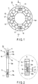
- a torque sensor 10 comprises a first structure (first region) 11, a second structure 12 (second region), a plurality of beams (third regions) 13, a first strain generation part 14, and a second strain generation part 15.
- the first structure 11, the second structure 12, the plurality of beams 13, the first strain generation part 14, and the second strain generation part 15 are formed of, for example, metal, but can be formed by using materials other than metal if a mechanical strength can be sufficiently obtained to the applied torque.
- the first structure 11 to which the torque is applied and the second structure 12 from which the torque is output have an annular shape.
- a diameter of the second structure 12 is smaller than a diameter of the first structure 11.
- the second structure 12 is disposed concentrically with the first structure 11, and the first structure 11 and the second structure 12 are connected by the plurality of beams 13 radially arranged, the first strain generation part 14, and the second strain generation part 15.
- the second structure 12 also includes a hollow portion 12a.
- the first strain generation part 14 and the second strain generation part 15 are arranged at positions symmetrical with respect to the centers of the first structure 11 and the second structure 12 (the center of action of the torque).
- the first strain generation part 14 comprises a first protrusion 14a, a second protrusion 14b, and a first strain body 16.
- the first protrusion 14a protrudes from the first structure 11, and the second protrusion 14b protrudes from the second structure 12.
- a first gap is provided between the first protrusion 14a and the second protrusion 14b, and the first protrusion 14a and the second protrusion 14b are connected by the first strain body 16.
- the first strain body 16 comprises, for example, a plurality of strain sensors (hereinafter, referred to as strain gauges) as resistors to be described later.
- the second strain generation part 15 comprises a third protrusion 15a, a fourth protrusion 15b, and a second strain body 17.
- the third protrusion 15a protrudes from the first structure 11, and the fourth protrusion 15b protrudes from the second structure 12.
- a second gap is provided between the third protrusion 15a and the fourth protrusion 15b, and the third protrusion 15a and the fourth protrusion 15b are connected by the second strain body 17.
- the second strain body 17 comprises, for example, a plurality of strain gauges as resistors to be described later.
- the first structure 11, the second structure 12, and the beams 13 have a first thickness T1
- the first strain generation part 14 and the second strain generation part 15 have a second thickness T2 smaller than the first thickness T1.
- the substantial thicknesses (second thickness T2) for obtaining the rigidity of the first strain generation part 14 and the second strain generation part 15 correspond to the thicknesses of the first strain body 16 and the second strain body 17, respectively. More specifically, when the first thickness T1 is, for example, 10 mm, the second thickness T1 is, for example, approximately 0.7 mm.
- the strength of the beams 13 is defined by the width of the beams 13 if the thicknesses of the first structure 11 and the second structure 12 are assumed to be equal.
- a substantial rotation angle of the first structure 11 to the second structure 12 is determined based on the plurality of beams 13 in accordance with the torque applied to the first structure 11.
- strain generated in the first strain generation part 14 and the second strain generation part 15 in accordance with the rotation angle of the first structure 11 to the second structure 12 is detected by the plurality of strain gauges provided in the first strain body 16 and the second strain body 17.
- the thickness of the first protrusion 14a, the second protrusion 14b, the third protrusion 15a, and the fourth protrusion 15b are set to, for example, a third thickness T3 which is smaller than the first thickness T1 and larger than the second thickness T2.
- the thickness of the first protrusion 14a, the second protrusion 14b, the third protrusion 15a, and the fourth protrusion 15b to the thickness T1 of the first structure 11 and the second structure 12 is variable.
- the sensitivity of the torque sensor 10 can be adjusted by adjusting the thicknesses T1, T2, and T3.
- Each of the length of the first protrusion 14a and the second protrusion 14b of the first strain generation part 14 and the length of the third protrusion 15a and the fourth protrusion 15b of the second strain generating part 15 is set to L1, and each of length L2 of a first gap provided between the first protrusion 14a and the second protrusion 14b and length L2 of a second gap provided between the third protrusion 15a and the fourth protrusion 15b of the second strain generation part 15 is set to be shorter than L1.
- the total length of the first protrusion 14a and the second protrusion 14b and the total length of the third protrusion 15a and the fourth protrusion 15b, that is, 2 ⁇ L1 are shorter than length L3 of each of the plurality of beams 13 ( FIG. 2 shows only the lengths L1 and L2 on the first strain generation part 14 side, but L3 is not shown).
- the amount of strain generated in the first strain generation part 14 and the second strain generation part 15 can be adjusted by adjusting these lengths L1, L2, and L3. More specifically, the length L2 of the first gap and the length L2 of the second gap are shorter than the length L1 of the first protrusion 14a, the second protrusion 14b, the third protrusion 15a, and the fourth protrusion 15b, and the first length L1 of the first protrusion 14a, the second protrusion 14b, the third protrusion 15a, and the fourth protrusion 15b is shorter than the length L3 of the plurality of beams 13. For this reason, when the torque is applied to the first structure 11, the amount of strain of the first strain generation part 14 and the second strain generation part 15 becomes larger than the amount of strain of the beams 13. Therefore, a bridge circuit to be described later can obtain a large gain.
- the allowable torque (maximum torque) and mechanical strength of the torque sensor 10 can be set based on, for example, the thickness and width of the first structure 11, the second structure 12 and the plurality of beams 13, independently of the first strain generation part 14 and the second strain generation part 15.
- the sensitivity of the torque sensor 10 can be set by the thickness of the first strain body 16 and the second strain body 17.
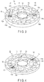
- FIG. 3 and FIG. 4 specifically show the first strain generation part 14 and the second strain generation part 15.
- the first strain generation part 14 includes a first accommodation part 14c for accommodating the first strain body 16, and the second strain generation part 15 includes a second accommodation part 15c for accommodating the second strain body 17.
- the first accommodation part 14c positions the first strain body 16 with respect to the first strain generation part 14, and the second accommodation part 15c positions the second strain body 17 with respect to the second strain generation part 15.
- the first accommodation part 14c is constituted by a substantially frame-shaped projection provided on the first projection 14a and the second projection 14b
- the second accommodation part 15c is constituted by a substantially frame-shaped projection provided on the third protrusion 15a and the fourth protrusion 15b.
- the first accommodation part 14c includes a gap corresponding to the gap between the first projection 14a and the second projection 14b
- the second accommodation part 15c includes a gap corresponding to the gap between the third protrusion 15a and the fourth protrusion 15b.
- the first strain body 16 and the second strain body 17 are accommodated in the first accommodation part 14c and the second accommodation part 15c from the upper sides of the first accommodation part 14c and the second accommodation part 15c, respectively.
- the first straining body 16 is fixed to the first projection 14a and the second projection 14b by, for example, welding, in a state in which the first strain body 16 and the second strain body 17 are accommodated in the first accommodation part 14c and the second accommodation part 15c, respectively.
- the second strain body 17 is fixed to the third protrusion 15a and the fourth protrusion 15b by, for example, welding.
- the method of fixing the first strain body 16 and the second strain body 17 is not limited to welding, but may be a method of fixing the first strain body 16 and the second strain body 17 to the first to fourth protrusions 14a to 15b with strength sufficient to the torque applied to the first strain body 16 and the second strain body 17.
- Wirings (not shown) of the first strain body 16 and the second strain body 17 are covered with an insulating member 32 (shown in FIG. 6 ).
- FIG. 5 shows an example of a strain gauge 21 provided on the first strain body 16 and the second strain body 17, and shows a cross-section of an end portion of the strain gage 21.
- the strain gauge 21 comprises, for example, an insulating film 21a, a thin film resistor (strain sensitive film) 21b, an adhesive film 21c, a wiring 21d, an adhesive film 21e, and a glass film 21f serving as a protective film.
- the insulating film 21a is provided on the first strain body 16 (second strain body 17) formed of metal
- the thin film resistor 21b composed of, for example, a Cr-N resistor is provided on the insulating film 21a.
- the thin film resistor 21b may have a linear shape, a shape bent at plural times, etc.
- a wiring 21d serving as an electrode lead formed of, for example, copper (Cu) is provided on the end of the thin film resistor 21b via an adhesive film 21c.
- the adhesive film 21e is provided on the wiring 21d.
- the insulating film 21a, the thin film resistor 21b, and the adhesive film 21e are covered with the glass film 21f.
- the adhesive film 21c enhances the adhesion between the wiring 21d and the thin film resistor 21b
- the adhesive film 21e enhances the adhesion between the wiring 21d and the glass film 21f.
- the adhesive films 21c and 21e are films containing, for example, chromium (Cr).
- the configuration of the strain gauge 21 is not limited to this.
- Each of the first strain body 16 and the second strain body 17 comprises, for example, two strain gauges 21 shown in FIG. 5 , and a bridge circuit to be described later is constituted by four strain gauges 21.
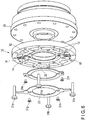
- FIG. 6 shows the relationship between the torque sensor 10 and, for example, a speed reducer 30 provided at one of the joints of the robot.
- the first structure 11 of the torque sensor 10 is attached to the speed reducer 30 by bolts 31a, 31b, 31c, and 31d.
- the speed reducer 30 is connected to a motor (not shown).
- the insulating member 32 is attached to the second structure 12 of the torque sensor 10 by the bolts 31e and 31f.
- the insulating member 32 covers lead wirings of a plurality of strain gauges 21 (not shown).
- the insulating member 32, the first strain generation part 14, and the second strain generation part 15 are covered with a lid 33.
- the lid 33 is attached to the second structure 12 by bolts 31g and 31h.
- the second structure 12 is attached to, for example, the other of joints of a robot (not shown).
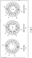
- FIG. 7(a), FIG. 7(b), and FIG. 7(c) show the operation of the torque sensor 10, and FIG. 7(a) shows a case where the torque is applied to the first structure 11, FIG. 7(b) shows a case where a thrust force is applied to the first structure 11 in the X-axis direction in the figure, and FIG. 7(c) shows a case where a thrust force is applied to the first structure 11 in the Y-axis direction in the figure.
- FIG. 8 schematically shows a bridge circuit 40 provided in the present torque sensor 10.
- each of the first strain body 16 of the first strain generation part 14 and the second strain body 17 of the second strain generation part 15 comprises two strain gauges 21. More specifically, the first strain body 16 comprises strain gauges 21-1 and 21-2, and the second strain body 17 comprises strain gauges 21-3 and 21-4.
- the first strain body 16 and the second strain body 17 are arranged symmetrically with respect to the centers of the first structure 11 and the second structure 12, and the strain gauges 21-1 and 21-2 and the strain gauges 21-3 and 21-4 are also arranged symmetrically with respect to the centers of the first structure 11 and the second structure 12.
- the strain gauges 21-1 and 21-3 are connected in series, and the strain gauges 21-2 and 21-4 are connected in series.
- the strain gauges 21-1 and 21-3 connected in series are connected in parallel to the strain gauges 21-2 and 21-4 connected in series.
- a power source Vo for example, 5V, is supplied to a connection point of the strain gauges 21-2 and 21-4, and a connection point of the strain gauges 21-1 and 21-3 is, for example, grounded.
- An output voltage Vout+ is output from a connection point of the strain gauges 21-1 and 21-2
- an output voltage Vout- is output from a connection point of the strain gauges 21-3 and 21-4.
- FIG. 9(a) shows the variation in resistance value of the bridge circuit 40 in a case where the torque is applied to the torque sensor 10 as shown in FIG. 7(a)
- FIG. 9(b) shows the variation in resistance value of the bridge circuit 40 in a case where, for example, the thrust force in the X-axis direction is applied to the torque sensor 10 as shown in FIG. 7(b)
- ⁇ R is the value of variation in the resistance.
- FIG. 10 shows results of obtaining the output voltage Vout of the torque sensor 10 under different conditions (1) to (6) from the equation (1).
- R ⁇ (1+ ⁇ T) indicates the resistance value at the time when the temperature coefficient of resistance is ⁇ and the temperature variation is ⁇ T.
- the output voltage Vout of the torque sensor 10 is 0V. That is, when the thrust force is applied to the first structure 11 and the second structure 12, and/or when a temperature variation is applied to the strain gauges 21-1 and 21-2, the thrust force and the temperature variation are canceled and each output voltage Vout of the torque sensor 10 is 0V.
- the torque sensor 10 when the torque is applied to the torque sensor 10 represented in (2), and when the torque is applied to the torque sensor 10 represented in (5) and the temperature variation is given to the strain gauges 21-1 and 21-2, - ⁇ R/R ⁇ Vo is output as the output voltage Vout of the torque sensor 10.
- the output voltage Vout is a value which does not include temperature coefficient ⁇ or temperature change ⁇ T of the resistance. Therefore, the torque sensor 10 can offset the thrust force and the temperature variation and detect only the torque.
- the first structure 11 and the second structure 12 are connected by the plurality of beams 13 and, furthermore, the first structure 11 and the second structure 12 are connected by the first strain generation part 14 and the second strain generation part 15.
- the thickness T1 of the plurality of beams 13 is set to be larger than the substantial thickness (thickness of the first strain body 16 and second strain body 17) T2 for obtaining the rigidity of the first strain generation part 14 and the second strain generation part 15.
- the allowable torque of the torque sensor 10 and the mechanical strength of the torque sensor 10 are defined by the first structure 11, the second structure 12, and the beams 13. Therefore, the allowable torque of the torque sensor 10 and the mechanical force of the torque sensor 10 can be freely set as needed by changing the thickness T1 of the first structure 11, the second structure 12 and the beams 13, or changing the number of the beams 13.
- first strain generation part 14 is configured by the first protrusion 14a and the second protrusion 14b provided at the first structure 11 and the second structure body 12, respectively, and the first strain generation part 16 including the strain gauges 21-1 and 21-2 which connect the first protrusion 14a and the second protrusion 14b
- second strain generation part 15 is configured by the third protrusion 15a and the fourth protrusion 15b provided at the first structure 11 and the second structure body 12, respectively, and the second strain generation part 17 provided with the strain gauges 21-3 and 21-4 which connect the third protrusion 15a and the fourth protrusion 15b.
- the first strain body 16 and the second strain body 17 are independent of the first structure 11, the second structure 12, the plurality of beams 13, the first protrusion 14a, the second protrusion 14b, the third protrusion 15a, and the fourth protrusion 15b. For this reason, the size including the shape, thickness and/or width of the first strain body 16 and the second strain body 17 can be set freely.
- the first strain body 16 and the second strain body 17 are independent of the first structure 11, the second structure 12, the plurality of beams 13, the first protrusion 14a, the second protrusion 14b, the third protrusion 15a, and the fourth protrusion 15b.
- the sensitivity and size of the strain gauges 21-1, 21-2, 21-3, and 21-4 provided on the first strain body 16 and the second strain body 17 can be set in accordance with the size of the first strain body 16 and the second strain body 17. Therefore, the sensitivity and the size of the strain gauges 21-1, 21-2, 21-3, and 21-4 can be set easily.
- the length L1 of the first gap provided between the first protrusion 14a and the second protrusion 14b of the first strain generation part 14, and the length L1 of the second gap provided between the third protrusion 15a and the fourth protrusion 15b of the second strain generation part 15 are shorter than the length L2 of the first protrusion 14a, the second protrusion 14b, the third protrusion 15a, and the fourth protrusion 15b, and the length L2 of the first protrusion 14a, the second protrusion 14b, the third protrusion 15a and the fourth protrusion 15b is shorter than the length L3 of the plurality of beams 13.
- the first strain generating part 14 and the second strain generating part 15 can generate strain larger than the strain of the beams 13.
- the first straining body 16 and the second straining body 17 can generate a large strain as compared with the beams 13, the gains of the strain gauges 21-1, 21-2, 21-3, and 21-4 provided at the first straining body 16 and the second straining body 17 can be made larger. Therefore, resistance to noise and detection accuracy of torque can be improved.
- first strain body 16 is configured separately from the first protrusion 14a and the second protrusion 14b
- second strain body 17 is configured separately from the third protrusion 15a and the fourth protrusion 15b.
- the fine strain gauges 21-1, 21-2, 21-3, and 21-4 can easily be formed on the first strain body 16 and the second strain body 17.
- the torque sensor 10 can be configured by attaching the first strain body 16 provided with the strain gauges 21-1 and 21-2 to the first protrusion 14a and the second protrusion 14b of the first strain generation part 14, and attaching the second strain body 17 provided with the strain gauges 21-3 and 21-4 to the third protrusion 15a and the fourth protrusion 15b of the second strain generation part 15. For this reason, the torque sensor 10 can be manufactured easily.
- first strain generation part 14 provided with the first strain body 16 and the second strain generation part 15 provided with the second strain body 17 are arranged at positions symmetrical with respect to the centers of the first structure 11 and the second structure 12. For this reason, the thrust force can be offset and the only torque can be detected.
- a pair of strain gauges 21-1 and 21-2 are provided at the first strain body 16, and a pair of strain gauges 21-3 and 21-4 are provided at the second strain body 17, and a bridge circuit 40 is composed of strain gauges 21-1, 21-2, 21-3, and 21-4. For this reason, the influence of the temperature coefficient of the strain gauges 21-1, 21-2, 21-3, and 21-4 can be offset.
- the second structure 12 includes a hollow portion 12a in the first structure 11 and the second structure 12 arranged concentrically. For this reason, a plurality of strain gauge wirings, and wirings necessary for control of a robot can be passed through the hollow portion 12a, and space can be used effectively.
- the first structure 11 and the second structure 12 are arranged concentrically, and the first structure 11 and the second structure 12 are connected by the plurality of beams 13.
- the present invention is not limited to this, but can employ the following configuration.
- the first structure and the second structure are configured linearly, and the first structure and the second structure are arranged in parallel.
- the first structure and the second structure are connected by the plurality of beams.
- a first sensor unit having a strain body provided with a resistor, and a second sensor unit having the same configuration as the first sensor unit are disposed at central portions in the longitudinal direction of the first structure and the second structure, and the first structure and the second structure are connected by the first sensor unit and the second sensor unit.
- the first sensor unit and the second sensor unit are arranged at positions where the central portions in the longitudinal direction of the second structure of the first sensor unit and the second structure of the second sensor unit are located at an equal distance from the action center of the torque, and the first sensor unit and the second sensor unit are parallel to each other. That is, the strain body of the first sensor unit and the strain body of the second sensor unit are arranged at symmetrical positions with respect to the action center of the torque. Also in this configuration, the same effects as the above embodiment can be obtained.
- the present invention is not limited to the above embodiments as it is, and at the implementation stage, the constituent elements can be modified and embodied without departing from the scope of the invention.
- various inventions can be formed by appropriate combinations of a plurality of constituent elements disclosed in the above embodiments. For example, some components may be deleted from all the components shown in the embodiment. Furthermore, components in different embodiments may be combined as appropriate.
- the torque sensor according to the embodiments of the present invention can be applied to, for example, a joint of a robot arm.
- 10 torque sensor, 11 ... first structure, 12 ... second structure, 13 ... beam, 14 ... first strain generation part, 14a ... first protrusion, 14b ... second protrusion, 15 ... second strain generation part, 15a ... third protrusion, 15b ... fourth protrusion, 16 ... first strain body, 17 ... second strain body, 21, 21-1, 21-2, 21-3, 21-4 ... strain gauge.
Landscapes
- Engineering & Computer Science (AREA)
- Physics & Mathematics (AREA)
- General Physics & Mathematics (AREA)
- Robotics (AREA)
- Mechanical Engineering (AREA)
- Human Computer Interaction (AREA)
- Chemical & Material Sciences (AREA)
- Analytical Chemistry (AREA)
- Force Measurement Appropriate To Specific Purposes (AREA)
- Manipulator (AREA)
- Measurement Of Force In General (AREA)
Applications Claiming Priority (2)
| Application Number | Priority Date | Filing Date | Title |
|---|---|---|---|
| JP2016237778A JP2018091813A (ja) | 2016-12-07 | 2016-12-07 | トルクセンサ |
| PCT/JP2017/035633 WO2018105209A1 (ja) | 2016-12-07 | 2017-09-29 | トルクセンサ |
Publications (3)
| Publication Number | Publication Date |
|---|---|
| EP3553485A1 true EP3553485A1 (de) | 2019-10-16 |
| EP3553485A4 EP3553485A4 (de) | 2020-08-19 |
| EP3553485B1 EP3553485B1 (de) | 2025-07-16 |
Family
ID=62491428
Family Applications (1)
| Application Number | Title | Priority Date | Filing Date |
|---|---|---|---|
| EP17879378.2A Active EP3553485B1 (de) | 2016-12-07 | 2017-09-29 | Drehmomentsensor |
Country Status (6)
| Country | Link |
|---|---|
| US (1) | US11085839B2 (de) |
| EP (1) | EP3553485B1 (de) |
| JP (1) | JP2018091813A (de) |
| KR (1) | KR102368172B1 (de) |
| CN (1) | CN109923389A (de) |
| WO (1) | WO2018105209A1 (de) |
Families Citing this family (25)
| Publication number | Priority date | Publication date | Assignee | Title |
|---|---|---|---|---|
| JP6808469B2 (ja) * | 2016-12-07 | 2021-01-06 | 日本電産コパル電子株式会社 | トルクセンサ |
| JP6987676B2 (ja) * | 2018-03-08 | 2022-01-05 | 日本電産コパル電子株式会社 | トルクセンサ |
| JP7091545B2 (ja) * | 2018-03-08 | 2022-06-27 | 日本電産コパル電子株式会社 | トルクセンサ |
| JP6968739B2 (ja) * | 2018-03-29 | 2021-11-17 | 日本電産コパル電子株式会社 | トルクセンサ |
| JP6910991B2 (ja) * | 2018-07-02 | 2021-07-28 | 日本電産コパル電子株式会社 | トルクセンサの支持装置 |
| JP6910990B2 (ja) * | 2018-07-02 | 2021-07-28 | 日本電産コパル電子株式会社 | トルクセンサの支持装置 |
| JP7066560B2 (ja) * | 2018-07-13 | 2022-05-13 | 日本電産コパル電子株式会社 | トルクセンサの取り付け構造 |
| CN112513603B (zh) | 2018-07-13 | 2022-02-22 | 日本电产科宝电子株式会社 | 扭矩传感器的安装结构 |
| JP2020012657A (ja) * | 2018-07-13 | 2020-01-23 | 日本電産コパル電子株式会社 | トルクセンサ |
| JP7059138B2 (ja) | 2018-07-13 | 2022-04-25 | 日本電産コパル電子株式会社 | トルクセンサの取り付け構造 |
| JP7062540B2 (ja) * | 2018-07-13 | 2022-05-06 | 日本電産コパル電子株式会社 | トルクセンサ |
| TWI716789B (zh) * | 2018-12-20 | 2021-01-21 | 財團法人工業技術研究院 | 多軸力感測裝置 |
| JP7159073B2 (ja) * | 2019-02-07 | 2022-10-24 | 日本電産コパル電子株式会社 | ロードセル |
| JP7159072B2 (ja) * | 2019-02-07 | 2022-10-24 | 日本電産コパル電子株式会社 | ロードセル |
| WO2021070665A1 (ja) * | 2019-10-09 | 2021-04-15 | 日本電産コパル電子株式会社 | 歪センサの固定装置とそれを用いたトルクセンサ |
| JP1667823S (de) * | 2019-11-29 | 2020-09-07 | ||
| JP1667822S (de) * | 2019-11-29 | 2020-09-07 | ||
| US20230010885A1 (en) * | 2019-12-13 | 2023-01-12 | Nagano Keiki Co., Ltd. | Torque sensor |
| JP7471825B2 (ja) * | 2020-01-07 | 2024-04-22 | キヤノン株式会社 | 検出装置、検出方法、制御方法、ロボット装置、物品の製造方法、プログラム、および記録媒体 |
| WO2021230173A1 (ja) * | 2020-05-13 | 2021-11-18 | アルプスアルパイン株式会社 | 力覚センサ装置 |
| CN112665765A (zh) * | 2020-12-01 | 2021-04-16 | 哈尔滨工业大学 | 一种基于并联分载原理的机器人高刚度关节力矩传感器 |
| CN112539862A (zh) * | 2020-12-04 | 2021-03-23 | 法奥意威(苏州)机器人系统有限公司 | 一种机器人关节的扭矩测量装置 |
| JP7574120B2 (ja) | 2021-03-22 | 2024-10-28 | ニデックコンポーネンツ株式会社 | トルクセンサ |
| JP7775123B2 (ja) | 2022-03-25 | 2025-11-25 | ニデックコンポーネンツ株式会社 | トルクセンサ |
| JP2024072155A (ja) * | 2022-11-15 | 2024-05-27 | 新東工業株式会社 | トルクセンサおよびロボット |
Family Cites Families (18)
| Publication number | Priority date | Publication date | Assignee | Title |
|---|---|---|---|---|
| JPS5640905B2 (de) | 1973-10-31 | 1981-09-24 | ||
| US5648617A (en) * | 1995-08-25 | 1997-07-15 | Applied Robotics, Inc. | Single axis robot force sensor assembly |
| US6038933A (en) * | 1997-07-15 | 2000-03-21 | Mts Systems Corporation | Multi-axis load cell |
| US20080204266A1 (en) * | 2004-02-03 | 2008-08-28 | Jussi Malmberg | Method and Device For Implementing Vibration Output Commands in Mobile Terminal Devices |
| EP1719991A4 (de) * | 2004-02-04 | 2007-04-11 | Ono Sokki Co Ltd | Drehmomentmessvorrichtung |
| JP4764619B2 (ja) * | 2004-08-23 | 2011-09-07 | 株式会社エー・アンド・デイ | 回転型分力計測装置 |
| JP4877665B2 (ja) * | 2006-01-16 | 2012-02-15 | 有限会社ケイテックシステム | 3軸力覚センサ |
| US7743672B2 (en) * | 2008-06-06 | 2010-06-29 | Kulite Semiconductor Products, Inc. | Multiple axis load cell controller |
| DE102009053043A1 (de) * | 2009-11-16 | 2011-05-19 | Baumer Innotec Ag | Kraftmesszelle zur Messung der Einspritzkraft beim Spritzgießen |
| JP5640905B2 (ja) | 2011-06-14 | 2014-12-17 | トヨタ自動車株式会社 | 起歪体及びこれを含む装置 |
| JP5699904B2 (ja) | 2011-10-28 | 2015-04-15 | トヨタ自動車株式会社 | 起歪体及びトルクセンサ |
| CN103076131B (zh) * | 2012-12-31 | 2014-12-17 | 东南大学 | 用于测量大型机械臂大力与小力矩的六维力与力矩传感器 |
| JP6135408B2 (ja) | 2013-09-04 | 2017-05-31 | トヨタ自動車株式会社 | トルクセンサ、駆動装置、及びロボット |
| CN104048791B (zh) * | 2014-06-24 | 2016-01-13 | 东南大学 | 一种低维间耦合的双十字梁型六维力和力矩传感器 |
| JP2017172983A (ja) * | 2016-03-18 | 2017-09-28 | 株式会社安川電機 | ロボット及びトルクセンサ |
| CN106153237A (zh) * | 2016-06-14 | 2016-11-23 | 南京神源生智能科技有限公司 | 一种小型六维力和力矩传感器 |
| CN105973515A (zh) * | 2016-06-28 | 2016-09-28 | 北京轻客智能科技有限责任公司 | 爪盘式功率计以及包括此爪盘式功率计的骑行装置 |
| JP6968739B2 (ja) * | 2018-03-29 | 2021-11-17 | 日本電産コパル電子株式会社 | トルクセンサ |
-
2016
- 2016-12-07 JP JP2016237778A patent/JP2018091813A/ja active Pending
-
2017
- 2017-09-29 EP EP17879378.2A patent/EP3553485B1/de active Active
- 2017-09-29 CN CN201780068876.1A patent/CN109923389A/zh active Pending
- 2017-09-29 KR KR1020197011293A patent/KR102368172B1/ko not_active Expired - Fee Related
- 2017-09-29 WO PCT/JP2017/035633 patent/WO2018105209A1/ja not_active Ceased
-
2019
- 2019-04-24 US US16/393,021 patent/US11085839B2/en not_active Expired - Fee Related
Also Published As
| Publication number | Publication date |
|---|---|
| KR102368172B1 (ko) | 2022-02-25 |
| WO2018105209A1 (ja) | 2018-06-14 |
| EP3553485A4 (de) | 2020-08-19 |
| JP2018091813A (ja) | 2018-06-14 |
| US20190250051A1 (en) | 2019-08-15 |
| EP3553485B1 (de) | 2025-07-16 |
| KR20190093556A (ko) | 2019-08-09 |
| CN109923389A (zh) | 2019-06-21 |
| US11085839B2 (en) | 2021-08-10 |
Similar Documents
| Publication | Publication Date | Title |
|---|---|---|
| EP3553485A1 (de) | Drehmomentsensor | |
| EP3553484B1 (de) | Drehmomentsensor | |
| JP6047703B2 (ja) | 力覚センサ | |
| US11499879B2 (en) | Torque sensor having a strain sensor | |
| JP6618128B2 (ja) | 力覚センサ及び力覚センサのブリッジ回路構成方法 | |
| US11408786B2 (en) | Torque sensor | |
| KR102241350B1 (ko) | 스트레인 게이지 및 다축력 센서 | |
| JP2018146309A (ja) | 力覚センサ | |
| JP2020012660A (ja) | トルクセンサ | |
| CN110857896B (zh) | 力传感器 | |
| JP2013234975A (ja) | 力覚センサ | |
| US9885624B2 (en) | Strain sensor, and load detection device using same | |
| JP6935602B2 (ja) | トルクセンサ | |
| JP7775123B2 (ja) | トルクセンサ | |
| WO2022209210A1 (ja) | 力覚センサ | |
| JP2006058211A (ja) | 歪みゲージ型センサ | |
| JP7323970B1 (ja) | トルクセンサ | |
| JP2025042874A (ja) | トルクセンサ | |
| JP5197101B2 (ja) | 可動テーブル装置 |
Legal Events
| Date | Code | Title | Description |
|---|---|---|---|
| STAA | Information on the status of an ep patent application or granted ep patent |
Free format text: STATUS: THE INTERNATIONAL PUBLICATION HAS BEEN MADE |
|
| PUAI | Public reference made under article 153(3) epc to a published international application that has entered the european phase |
Free format text: ORIGINAL CODE: 0009012 |
|
| STAA | Information on the status of an ep patent application or granted ep patent |
Free format text: STATUS: REQUEST FOR EXAMINATION WAS MADE |
|
| 17P | Request for examination filed |
Effective date: 20190425 |
|
| AK | Designated contracting states |
Kind code of ref document: A1 Designated state(s): AL AT BE BG CH CY CZ DE DK EE ES FI FR GB GR HR HU IE IS IT LI LT LU LV MC MK MT NL NO PL PT RO RS SE SI SK SM TR |
|
| AX | Request for extension of the european patent |
Extension state: BA ME |
|
| DAV | Request for validation of the european patent (deleted) | ||
| DAX | Request for extension of the european patent (deleted) | ||
| A4 | Supplementary search report drawn up and despatched |
Effective date: 20200722 |
|
| RIC1 | Information provided on ipc code assigned before grant |
Ipc: G01L 1/22 20060101ALI20200716BHEP Ipc: B25J 13/08 20060101ALI20200716BHEP Ipc: G01L 3/10 20060101AFI20200716BHEP |
|
| STAA | Information on the status of an ep patent application or granted ep patent |
Free format text: STATUS: EXAMINATION IS IN PROGRESS |
|
| 17Q | First examination report despatched |
Effective date: 20230918 |
|
| GRAP | Despatch of communication of intention to grant a patent |
Free format text: ORIGINAL CODE: EPIDOSNIGR1 |
|
| STAA | Information on the status of an ep patent application or granted ep patent |
Free format text: STATUS: GRANT OF PATENT IS INTENDED |
|
| INTG | Intention to grant announced |
Effective date: 20250218 |
|
| GRAS | Grant fee paid |
Free format text: ORIGINAL CODE: EPIDOSNIGR3 |
|
| GRAA | (expected) grant |
Free format text: ORIGINAL CODE: 0009210 |
|
| STAA | Information on the status of an ep patent application or granted ep patent |
Free format text: STATUS: THE PATENT HAS BEEN GRANTED |
|
| AK | Designated contracting states |
Kind code of ref document: B1 Designated state(s): AL AT BE BG CH CY CZ DE DK EE ES FI FR GB GR HR HU IE IS IT LI LT LU LV MC MK MT NL NO PL PT RO RS SE SI SK SM TR |
|
| REG | Reference to a national code |
Ref country code: GB Ref legal event code: FG4D |
|
| REG | Reference to a national code |
Ref country code: CH Ref legal event code: EP |
|
| REG | Reference to a national code |
Ref country code: DE Ref legal event code: R096 Ref document number: 602017090667 Country of ref document: DE |
|
| REG | Reference to a national code |
Ref country code: IE Ref legal event code: FG4D |
|
| REG | Reference to a national code |
Ref country code: NL Ref legal event code: MP Effective date: 20250716 |
|
| PG25 | Lapsed in a contracting state [announced via postgrant information from national office to epo] |
Ref country code: PT Free format text: LAPSE BECAUSE OF FAILURE TO SUBMIT A TRANSLATION OF THE DESCRIPTION OR TO PAY THE FEE WITHIN THE PRESCRIBED TIME-LIMIT Effective date: 20251117 |
|
| PG25 | Lapsed in a contracting state [announced via postgrant information from national office to epo] |
Ref country code: NL Free format text: LAPSE BECAUSE OF FAILURE TO SUBMIT A TRANSLATION OF THE DESCRIPTION OR TO PAY THE FEE WITHIN THE PRESCRIBED TIME-LIMIT Effective date: 20250716 |
|
| REG | Reference to a national code |
Ref country code: AT Ref legal event code: MK05 Ref document number: 1814408 Country of ref document: AT Kind code of ref document: T Effective date: 20250716 |
|
| PG25 | Lapsed in a contracting state [announced via postgrant information from national office to epo] |
Ref country code: IS Free format text: LAPSE BECAUSE OF FAILURE TO SUBMIT A TRANSLATION OF THE DESCRIPTION OR TO PAY THE FEE WITHIN THE PRESCRIBED TIME-LIMIT Effective date: 20251116 |
|
| PGFP | Annual fee paid to national office [announced via postgrant information from national office to epo] |
Ref country code: DE Payment date: 20250930 Year of fee payment: 9 |
|
| PG25 | Lapsed in a contracting state [announced via postgrant information from national office to epo] |
Ref country code: NO Free format text: LAPSE BECAUSE OF FAILURE TO SUBMIT A TRANSLATION OF THE DESCRIPTION OR TO PAY THE FEE WITHIN THE PRESCRIBED TIME-LIMIT Effective date: 20251016 |
|
| REG | Reference to a national code |
Ref country code: LT Ref legal event code: MG9D |
|
| PG25 | Lapsed in a contracting state [announced via postgrant information from national office to epo] |
Ref country code: AT Free format text: LAPSE BECAUSE OF FAILURE TO SUBMIT A TRANSLATION OF THE DESCRIPTION OR TO PAY THE FEE WITHIN THE PRESCRIBED TIME-LIMIT Effective date: 20250716 |
|
| PG25 | Lapsed in a contracting state [announced via postgrant information from national office to epo] |
Ref country code: FI Free format text: LAPSE BECAUSE OF FAILURE TO SUBMIT A TRANSLATION OF THE DESCRIPTION OR TO PAY THE FEE WITHIN THE PRESCRIBED TIME-LIMIT Effective date: 20250716 |
|
| PG25 | Lapsed in a contracting state [announced via postgrant information from national office to epo] |
Ref country code: HR Free format text: LAPSE BECAUSE OF FAILURE TO SUBMIT A TRANSLATION OF THE DESCRIPTION OR TO PAY THE FEE WITHIN THE PRESCRIBED TIME-LIMIT Effective date: 20250716 |
|
| PG25 | Lapsed in a contracting state [announced via postgrant information from national office to epo] |
Ref country code: GR Free format text: LAPSE BECAUSE OF FAILURE TO SUBMIT A TRANSLATION OF THE DESCRIPTION OR TO PAY THE FEE WITHIN THE PRESCRIBED TIME-LIMIT Effective date: 20251017 |
|
| PG25 | Lapsed in a contracting state [announced via postgrant information from national office to epo] |
Ref country code: SE Free format text: LAPSE BECAUSE OF FAILURE TO SUBMIT A TRANSLATION OF THE DESCRIPTION OR TO PAY THE FEE WITHIN THE PRESCRIBED TIME-LIMIT Effective date: 20250716 |
|
| PG25 | Lapsed in a contracting state [announced via postgrant information from national office to epo] |
Ref country code: LV Free format text: LAPSE BECAUSE OF FAILURE TO SUBMIT A TRANSLATION OF THE DESCRIPTION OR TO PAY THE FEE WITHIN THE PRESCRIBED TIME-LIMIT Effective date: 20250716 |
|
| PG25 | Lapsed in a contracting state [announced via postgrant information from national office to epo] |
Ref country code: BG Free format text: LAPSE BECAUSE OF FAILURE TO SUBMIT A TRANSLATION OF THE DESCRIPTION OR TO PAY THE FEE WITHIN THE PRESCRIBED TIME-LIMIT Effective date: 20250716 Ref country code: PL Free format text: LAPSE BECAUSE OF FAILURE TO SUBMIT A TRANSLATION OF THE DESCRIPTION OR TO PAY THE FEE WITHIN THE PRESCRIBED TIME-LIMIT Effective date: 20250716 |
|
| PG25 | Lapsed in a contracting state [announced via postgrant information from national office to epo] |
Ref country code: RS Free format text: LAPSE BECAUSE OF FAILURE TO SUBMIT A TRANSLATION OF THE DESCRIPTION OR TO PAY THE FEE WITHIN THE PRESCRIBED TIME-LIMIT Effective date: 20251016 |
|
| PG25 | Lapsed in a contracting state [announced via postgrant information from national office to epo] |
Ref country code: ES Free format text: LAPSE BECAUSE OF FAILURE TO SUBMIT A TRANSLATION OF THE DESCRIPTION OR TO PAY THE FEE WITHIN THE PRESCRIBED TIME-LIMIT Effective date: 20250716 |
|
| PG25 | Lapsed in a contracting state [announced via postgrant information from national office to epo] |
Ref country code: RO Free format text: LAPSE BECAUSE OF FAILURE TO SUBMIT A TRANSLATION OF THE DESCRIPTION OR TO PAY THE FEE WITHIN THE PRESCRIBED TIME-LIMIT Effective date: 20250716 |
|
| PG25 | Lapsed in a contracting state [announced via postgrant information from national office to epo] |
Ref country code: SM Free format text: LAPSE BECAUSE OF FAILURE TO SUBMIT A TRANSLATION OF THE DESCRIPTION OR TO PAY THE FEE WITHIN THE PRESCRIBED TIME-LIMIT Effective date: 20250716 |
|
| PG25 | Lapsed in a contracting state [announced via postgrant information from national office to epo] |
Ref country code: DK Free format text: LAPSE BECAUSE OF FAILURE TO SUBMIT A TRANSLATION OF THE DESCRIPTION OR TO PAY THE FEE WITHIN THE PRESCRIBED TIME-LIMIT Effective date: 20250716 |
|
| PG25 | Lapsed in a contracting state [announced via postgrant information from national office to epo] |
Ref country code: IT Free format text: LAPSE BECAUSE OF FAILURE TO SUBMIT A TRANSLATION OF THE DESCRIPTION OR TO PAY THE FEE WITHIN THE PRESCRIBED TIME-LIMIT Effective date: 20250716 |
|
| PG25 | Lapsed in a contracting state [announced via postgrant information from national office to epo] |
Ref country code: CZ Free format text: LAPSE BECAUSE OF FAILURE TO SUBMIT A TRANSLATION OF THE DESCRIPTION OR TO PAY THE FEE WITHIN THE PRESCRIBED TIME-LIMIT Effective date: 20250716 |
|
| PG25 | Lapsed in a contracting state [announced via postgrant information from national office to epo] |
Ref country code: SK Free format text: LAPSE BECAUSE OF FAILURE TO SUBMIT A TRANSLATION OF THE DESCRIPTION OR TO PAY THE FEE WITHIN THE PRESCRIBED TIME-LIMIT Effective date: 20250716 Ref country code: EE Free format text: LAPSE BECAUSE OF FAILURE TO SUBMIT A TRANSLATION OF THE DESCRIPTION OR TO PAY THE FEE WITHIN THE PRESCRIBED TIME-LIMIT Effective date: 20250716 |