EP3553321A1 - Hlk-gebläseeinlass - Google Patents
Hlk-gebläseeinlass Download PDFInfo
- Publication number
- EP3553321A1 EP3553321A1 EP19167566.9A EP19167566A EP3553321A1 EP 3553321 A1 EP3553321 A1 EP 3553321A1 EP 19167566 A EP19167566 A EP 19167566A EP 3553321 A1 EP3553321 A1 EP 3553321A1
- Authority
- EP
- European Patent Office
- Prior art keywords
- fan housing
- fan
- apexes
- inlet
- nadirs
- Prior art date
- Legal status (The legal status is an assumption and is not a legal conclusion. Google has not performed a legal analysis and makes no representation as to the accuracy of the status listed.)
- Granted
Links
- 239000003507 refrigerant Substances 0.000 claims description 12
- 239000002991 molded plastic Substances 0.000 claims description 3
- 238000001816 cooling Methods 0.000 description 7
- 238000010438 heat treatment Methods 0.000 description 7
- 238000000926 separation method Methods 0.000 description 7
- 229910052751 metal Inorganic materials 0.000 description 6
- 239000002184 metal Substances 0.000 description 6
- 238000011144 upstream manufacturing Methods 0.000 description 5
- 230000001133 acceleration Effects 0.000 description 3
- 238000010521 absorption reaction Methods 0.000 description 2
- 238000004378 air conditioning Methods 0.000 description 2
- 238000010276 construction Methods 0.000 description 2
- 210000003141 lower extremity Anatomy 0.000 description 2
- 239000000463 material Substances 0.000 description 2
- 230000009467 reduction Effects 0.000 description 2
- 229910000838 Al alloy Inorganic materials 0.000 description 1
- 229910000851 Alloy steel Inorganic materials 0.000 description 1
- 239000004743 Polypropylene Substances 0.000 description 1
- 238000013459 approach Methods 0.000 description 1
- 239000011324 bead Substances 0.000 description 1
- 238000000071 blow moulding Methods 0.000 description 1
- 125000004122 cyclic group Chemical group 0.000 description 1
- 230000001419 dependent effect Effects 0.000 description 1
- 238000012938 design process Methods 0.000 description 1
- 230000004069 differentiation Effects 0.000 description 1
- 230000000694 effects Effects 0.000 description 1
- 210000003414 extremity Anatomy 0.000 description 1
- 239000012530 fluid Substances 0.000 description 1
- 239000006260 foam Substances 0.000 description 1
- 238000002347 injection Methods 0.000 description 1
- 239000007924 injection Substances 0.000 description 1
- 239000007788 liquid Substances 0.000 description 1
- 238000000034 method Methods 0.000 description 1
- 238000012986 modification Methods 0.000 description 1
- 230000004048 modification Effects 0.000 description 1
- 238000000465 moulding Methods 0.000 description 1
- 230000002093 peripheral effect Effects 0.000 description 1
- -1 polypropylene Polymers 0.000 description 1
- 229920001155 polypropylene Polymers 0.000 description 1
- 230000002250 progressing effect Effects 0.000 description 1
- 230000003014 reinforcing effect Effects 0.000 description 1
- 239000010959 steel Substances 0.000 description 1
- 230000002123 temporal effect Effects 0.000 description 1
- 238000003856 thermoforming Methods 0.000 description 1
- 230000007704 transition Effects 0.000 description 1
- 238000009423 ventilation Methods 0.000 description 1
Images





Classifications
-
- F—MECHANICAL ENGINEERING; LIGHTING; HEATING; WEAPONS; BLASTING
- F04—POSITIVE - DISPLACEMENT MACHINES FOR LIQUIDS; PUMPS FOR LIQUIDS OR ELASTIC FLUIDS
- F04D—NON-POSITIVE-DISPLACEMENT PUMPS
- F04D29/00—Details, component parts, or accessories
- F04D29/40—Casings; Connections of working fluid
- F04D29/52—Casings; Connections of working fluid for axial pumps
- F04D29/54—Fluid-guiding means, e.g. diffusers
- F04D29/541—Specially adapted for elastic fluid pumps
- F04D29/545—Ducts
-
- F—MECHANICAL ENGINEERING; LIGHTING; HEATING; WEAPONS; BLASTING
- F24—HEATING; RANGES; VENTILATING
- F24F—AIR-CONDITIONING; AIR-HUMIDIFICATION; VENTILATION; USE OF AIR CURRENTS FOR SCREENING
- F24F1/00—Room units for air-conditioning, e.g. separate or self-contained units or units receiving primary air from a central station
- F24F1/06—Separate outdoor units, e.g. outdoor unit to be linked to a separate room comprising a compressor and a heat exchanger
- F24F1/38—Fan details of outdoor units, e.g. bell-mouth shaped inlets or fan mountings
-
- F—MECHANICAL ENGINEERING; LIGHTING; HEATING; WEAPONS; BLASTING
- F04—POSITIVE - DISPLACEMENT MACHINES FOR LIQUIDS; PUMPS FOR LIQUIDS OR ELASTIC FLUIDS
- F04D—NON-POSITIVE-DISPLACEMENT PUMPS
- F04D25/00—Pumping installations or systems
- F04D25/02—Units comprising pumps and their driving means
- F04D25/08—Units comprising pumps and their driving means the working fluid being air, e.g. for ventilation
-
- F—MECHANICAL ENGINEERING; LIGHTING; HEATING; WEAPONS; BLASTING
- F04—POSITIVE - DISPLACEMENT MACHINES FOR LIQUIDS; PUMPS FOR LIQUIDS OR ELASTIC FLUIDS
- F04D—NON-POSITIVE-DISPLACEMENT PUMPS
- F04D27/00—Control, e.g. regulation, of pumps, pumping installations or pumping systems specially adapted for elastic fluids
- F04D27/006—Control, e.g. regulation, of pumps, pumping installations or pumping systems specially adapted for elastic fluids by influencing fluid temperatures
-
- F—MECHANICAL ENGINEERING; LIGHTING; HEATING; WEAPONS; BLASTING
- F04—POSITIVE - DISPLACEMENT MACHINES FOR LIQUIDS; PUMPS FOR LIQUIDS OR ELASTIC FLUIDS
- F04D—NON-POSITIVE-DISPLACEMENT PUMPS
- F04D29/00—Details, component parts, or accessories
- F04D29/002—Details, component parts, or accessories especially adapted for elastic fluid pumps
-
- F—MECHANICAL ENGINEERING; LIGHTING; HEATING; WEAPONS; BLASTING
- F04—POSITIVE - DISPLACEMENT MACHINES FOR LIQUIDS; PUMPS FOR LIQUIDS OR ELASTIC FLUIDS
- F04D—NON-POSITIVE-DISPLACEMENT PUMPS
- F04D29/00—Details, component parts, or accessories
- F04D29/40—Casings; Connections of working fluid
- F04D29/52—Casings; Connections of working fluid for axial pumps
- F04D29/522—Casings; Connections of working fluid for axial pumps especially adapted for elastic fluid pumps
-
- F—MECHANICAL ENGINEERING; LIGHTING; HEATING; WEAPONS; BLASTING
- F04—POSITIVE - DISPLACEMENT MACHINES FOR LIQUIDS; PUMPS FOR LIQUIDS OR ELASTIC FLUIDS
- F04D—NON-POSITIVE-DISPLACEMENT PUMPS
- F04D29/00—Details, component parts, or accessories
- F04D29/40—Casings; Connections of working fluid
- F04D29/52—Casings; Connections of working fluid for axial pumps
- F04D29/54—Fluid-guiding means, e.g. diffusers
- F04D29/541—Specially adapted for elastic fluid pumps
- F04D29/545—Ducts
- F04D29/547—Ducts having a special shape in order to influence fluid flow
-
- F—MECHANICAL ENGINEERING; LIGHTING; HEATING; WEAPONS; BLASTING
- F04—POSITIVE - DISPLACEMENT MACHINES FOR LIQUIDS; PUMPS FOR LIQUIDS OR ELASTIC FLUIDS
- F04D—NON-POSITIVE-DISPLACEMENT PUMPS
- F04D29/00—Details, component parts, or accessories
- F04D29/70—Suction grids; Strainers; Dust separation; Cleaning
- F04D29/701—Suction grids; Strainers; Dust separation; Cleaning especially adapted for elastic fluid pumps
- F04D29/703—Suction grids; Strainers; Dust separation; Cleaning especially adapted for elastic fluid pumps specially for fans, e.g. fan guards
-
- F—MECHANICAL ENGINEERING; LIGHTING; HEATING; WEAPONS; BLASTING
- F04—POSITIVE - DISPLACEMENT MACHINES FOR LIQUIDS; PUMPS FOR LIQUIDS OR ELASTIC FLUIDS
- F04D—NON-POSITIVE-DISPLACEMENT PUMPS
- F04D3/00—Axial-flow pumps
-
- F—MECHANICAL ENGINEERING; LIGHTING; HEATING; WEAPONS; BLASTING
- F05—INDEXING SCHEMES RELATING TO ENGINES OR PUMPS IN VARIOUS SUBCLASSES OF CLASSES F01-F04
- F05D—INDEXING SCHEME FOR ASPECTS RELATING TO NON-POSITIVE-DISPLACEMENT MACHINES OR ENGINES, GAS-TURBINES OR JET-PROPULSION PLANTS
- F05D2250/00—Geometry
- F05D2250/50—Inlet or outlet
- F05D2250/51—Inlet
Definitions
- the outdoor unit has a generally square footprint with the heat exchanger wrapping around four sides and three corners of that footprint between two headers.
- the compressor is positioned within a central cavity surrounded by the heat exchanger on a base of the unit.
- a service panel of the housing is mounted aligned with the gap and carries the inverter.
- the fan is mounted atop the outdoor unit and draws air inward through the heat exchanger to the central cavity and then exhausts it upward.
- the invention provides a fan housing for accommodating a fan rotating about a central axis.
- the fan housing comprises: an inlet; a diffuser; an inner diameter (ID) surface facing the central axis; and an outer diameter (OD) surface facing away from the central axis.
- a rim at the inlet has a plurality of apexes and a plurality of nadirs.
- the housing has a mounting flange.
- the apexes are of protrusions along an underside of the mounting flange protruding downward and radially outward relative to the central axis.
- the inner diameter surface and the outer diameter surface each have convex portions. At least at a given axial position, respective radial positions of the inner diameter surface and outer diameter surface convex portions may vary in the circumferential direction around the central axis.
- the outer diameter surface convex portion extends over a longitudinal span (H 2 ) of 5% to 40% of a throat diameter (D THROAT ) and a radial span (R S ) of 3% to 20% of D THROAT .
- the radial span (R S ) is at least 200% of the radial span (R S ) at the nadirs.
- the radial span (R S ) is 200% to 1000% of the radial span (R S ) at the nadirs.
- the apexes are axially spaced from the nadirs by a height H 1 of at least 3% of a throat diameter (D THROAT ).
- the apexes are axially spaced from the nadirs by said height H 1 of 4% to 12% of the throat diameter (D THROAT ).
- the fan housing comprises a top cover mated to a lower member, the lower member being of molded plastic and including the mounting flange.
- a climate control outdoor unit comprising a fan housing as discussed above and further comprising: a compressor having an electric motor; a refrigerant-air heat exchanger coupled to the compressor and extending around the central axis between a first header and a second header; and an electric fan encircled by the fan housing and positioned to drive an air flow along an air flowpath across the refrigerant-air heat exchanger then through the inlet and out the diffuser.
- the refrigerant air heat exchanger has a footprint with four sides and four corners, an inter-header gap at one of the four corners; the apexes are aligned with respective ones of the four corners; and the nadirs are aligned with respective ones of the four sides.
- the electric fan is atop the outdoor unit.
- a fan housing for accommodating a fan rotating about a central axis, the fan housing comprising: an inlet; a diffuser; an inner diameter (ID) surface facing the central axis; and an outer diameter (OD) surface facing away from the central axis.
- the outer diameter surface In central longitudinal section, the outer diameter surface has a convex portion.
- the inner diameter surface In said central longitudinal section, the inner diameter surface has a convex portion. At least at a given axial position, respective radial positions of the inner diameter surface and outer diameter surface convex portions vary in the circumferential direction around the central axis.
- a climate control outdoor unit comprising: a compressor having an electric motor; a refrigerant-air heat exchanger coupled to the compressor and extending around a central axis between a first header and a second header; a fan housing having a lower inlet and an upper diffuser; and an electric fan encircled by the fan housing and positioned to drive an air flow along an air flowpath across the refrigerant-air heat exchanger then through the inlet and out the diffuser.
- the fan duct inlet comprises means for limiting an inlet flow separation and reducing inflow non-uniformities about the central axis.
- the refrigerant air heat exchanger has a footprint with four sides and four corners, an inter-header gap at one of the four corners; the inlet has first portions aligned with the three remaining corners and second portions aligned with the four sides; and the first portions protrude axially beyond the second portions.
- HVAC heating, ventilation, and air conditioning
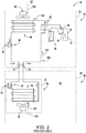
- FIG. 1 shows one example of an HVAC system 20 having an outdoor unit 22 (having a housing 23) and an indoor unit 24 (having a housing 25).
- the indoor unit 24 is within the interior 26 of a building 28.
- the exemplary outdoor unit 22 is a residential heat pump having both heating ( FIG. 1 ) and cooling ( FIG. 2 ) modes.
- the exemplary heat pump outdoor unit contains an electrically-powered compressor 30 having a motor 32.
- the compressor drives a refrigerant flow along a refrigerant flowpath entering the compressor at a suction port 34 and exiting the compressor at a discharge port 36.
- the various illustrated lines may be of conventional refrigerant line/conduit construction.
- the exemplary outdoor unit further includes an expansion device 44 for use in the heating mode (e.g., a thermal expansion valve, electronic expansion valve, orifice, or the like).
- a check valve bypass 46 is provided to bypass the expansion device 44 in the cooling mode.
- the indoor unit includes a heating mode expansion device 54 and a bypassing check valve 56.
- the exemplary outdoor unit further includes an accumulator 60 and one or more switching valves for switching between the heating mode and the cooling mode.
- the exemplary illustrated switching valve is a four-way valve 62.
- a flow 510 of refrigerant is compressed by the compressor and passes along a refrigerant flowpath 511 from the discharge port through the exemplary switching valve 62 along a line (vapor line) passing out from the outdoor unit and entering the building to ultimately enter the indoor unit to feed the indoor heat exchanger 50.
- the indoor heat exchanger 50 serves as a heat rejection heat exchanger rejecting heat to the air flow 522 (e.g., acting as a condenser or gas cooler).
- the cooled refrigerant flow then passes through the bypass 56 and back out of the indoor unit and building via a line (liquid line) to re-enter the outdoor unit.
- FIG. 1 shows an exemplary pair of service valves 70 and 72 in the outdoor unit allowing service thereof.
- the refrigerant After passing into the outdoor unit, the refrigerant proceeds through the expansion device 44 to the heat exchanger 40 which therefore serves conventionally as a heat absorption heat exchanger or evaporator absorbing heat from the air flow 520. The refrigerant then returns via the valve 62 and exemplary accumulator 60 to the suction port 34.
- the FIG. 2 cooling mode generally reverses direction of flow through the heat exchangers with the compressed refrigerant passing initially to the outdoor heat exchanger, then through the bypass 46 and through the expansion device 54 and indoor heat exchanger 50 to ultimately return.
- the outdoor heat exchanger serves as a heat rejection heat exchanger
- the indoor heat exchanger serves as a heat absorption heat exchanger rejecting heat to and absorbing heat from their respective associated air flows.
- the exemplary compressor motor 32 is powered by an inverter. Inverter cooling is a critical factor in system operation.
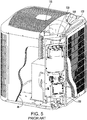
- FIG. 3 shows an exemplary outdoor unit 22.
- the outdoor unit has a base (base pan) 100 of generally square (e.g., with rounded or faceted corners) planform.
- the base pan supports the remainder of the outdoor unit components.
- Alternative coils can be of other planforms such as non-square rectangles or triangles of other polygons. Yet other coils may be oriented differently (e.g., V-coils where the shroud is above the V).
- the base pan forms a portion of the housing 23.
- the housing extends upward to include a top cover 102.
- one or more louver panels 104 and/or corner posts 105 may connect the base pan to the top cover.
- the top cover may be an assembly carrying the fan 42 and integrated with a housing/shroud (discussed below) of said fan.
- the exemplary fan and its motor define a central vertical axis 500 shared with the remainder of the outdoor unit.
- the top cover assembly may include a screen or fan guard 110.
- the louver openings form an air inlet along the outdoor unit air flowpath and the top cover fan guard openings form an air outlet.
- the exemplary outdoor heat exchanger 40 comprises a tube array wrapping generally around four sides and three corners of the footprint of the outdoor unit between a first header 120 and a second header 122 (shown in FIG. 5 ).
- a gap 123 between the two headers is aligned generally with one corner 124 ( FIG. 4 , shown with top cover 102 and fan guard 110 locally cut-away) of the footprint of the outdoor unit.
- a control box 130 FIG. 5 ) may be vertically mounted along this corner and contain the compressor motor control/inverter unit 132 and other associated components.
- the compressor (not shown) may be located centrally surrounded by the outdoor heat exchanger supported atop the base pan.
- Exemplary input power is single phase AC (e.g., nominal 220V, 60Hz).
- Exemplary output of the inverter unit is three-phase AC (e.g., varying in voltage, current, and frequency). Inverter power is typically limited by current and inverter temperature.
- Exemplary mounting may be via screwing to the fan guard 110 or to a framework (not shown) mounted across an upper end of an opening 180 through the top cover.
- the exemplary top cover 102 combines with a lower member 182 having an opening 183 to define a fan housing 184 (aka, fan shroud or unit outlet duct) surrounding the fan impeller.
- FIG. 7 shows the assembled top cover 102 and lower member 182 forming an outlet duct 184 with a vertical passage 186 therethrough.
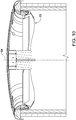
- FIG. 9 shows the top cover inboard or inner diameter (ID) surface 200 having a downstream divergent shape to serve as a diffuser 202.
- ID inner diameter
- a minimum ID location or throat 204 on the outlet duct is proximate a junction between the top cover ID surface 200 and the ID surface 210 of the member 182.
- the junction may be formed by abutting top cover lower rim 206 and member 182 upper rim 208.
- this does not have to be the case and, as is discussed below, even in other such two-piece duct combinations the boundary can be along one or the other of the two pieces. And, additionally, combinations of more pieces are possible and single-piece ducts are also possible.
- the member 182 forms an inlet 212 (upstream of the throat) for the fan with a generally downstream convergent surface extending from a lower extremity 220.
- An exemplary R S at the apexes is at least 5% of D THROAT , more particularly, 6% to 25% or 6% to 15%.
- An exemplary R S at the nadirs is at least 1% of D THROAT , more particularly, 1% to 10% or 2% to 6%.
- R S at the apexes may be at least 200% R S at the nadirs, or 200% to 1000% or 250% to 1000%.
- Technically R S at the nadirs could go to zero when the troughs might go to the flange.
- the lobed inlet structure may be adopted as a retrofit of an existing unit having an existing top cover 900.
- the existing top cover may be preserved/maintained and the added lower member 182 may mate with the top cover 900 to downwardly extend the resulting outlet duct below the rim 902 and define both the protuberant structure generally (e.g., shifting airflow away from the outer surface of the sheet metal) and defining the particular discrete protrusions/lobes.
- the existing top cover may define the inlet ID surface until the lower rim 902 of the top cover.
- the lower member may be a molded plastic material. This can be a relatively structural molding (e.g., injection molded) with reinforcing webs/ribs. Or it may be a thin wall structure such as a blow molding or sheet thermoforming. Yet further variations include forming the lower member of expanded bead material (e.g., expanded polypropylene (EPP)) or foams. Alternatively, a sheet metal stamping could be used for the lower member.
- EPP expanded polypropylene
Landscapes
- Engineering & Computer Science (AREA)
- Mechanical Engineering (AREA)
- General Engineering & Computer Science (AREA)
- Physics & Mathematics (AREA)
- Fluid Mechanics (AREA)
- Chemical & Material Sciences (AREA)
- Combustion & Propulsion (AREA)
- Other Air-Conditioning Systems (AREA)
- Structures Of Non-Positive Displacement Pumps (AREA)
Priority Applications (1)
| Application Number | Priority Date | Filing Date | Title |
|---|---|---|---|
| EP19211215.9A EP3633210B1 (de) | 2018-04-10 | 2019-04-05 | Einlass für hlk-gebläse |
Applications Claiming Priority (1)
| Application Number | Priority Date | Filing Date | Title |
|---|---|---|---|
| US201862655411P | 2018-04-10 | 2018-04-10 |
Related Child Applications (2)
| Application Number | Title | Priority Date | Filing Date |
|---|---|---|---|
| EP19211215.9A Division EP3633210B1 (de) | 2018-04-10 | 2019-04-05 | Einlass für hlk-gebläse |
| EP19211215.9A Division-Into EP3633210B1 (de) | 2018-04-10 | 2019-04-05 | Einlass für hlk-gebläse |
Publications (2)
| Publication Number | Publication Date |
|---|---|
| EP3553321A1 true EP3553321A1 (de) | 2019-10-16 |
| EP3553321B1 EP3553321B1 (de) | 2021-08-11 |
Family
ID=66101942
Family Applications (2)
| Application Number | Title | Priority Date | Filing Date |
|---|---|---|---|
| EP19211215.9A Active EP3633210B1 (de) | 2018-04-10 | 2019-04-05 | Einlass für hlk-gebläse |
| EP19167566.9A Active EP3553321B1 (de) | 2018-04-10 | 2019-04-05 | Hlk-gebläseeinlass |
Family Applications Before (1)
| Application Number | Title | Priority Date | Filing Date |
|---|---|---|---|
| EP19211215.9A Active EP3633210B1 (de) | 2018-04-10 | 2019-04-05 | Einlass für hlk-gebläse |
Country Status (4)
| Country | Link |
|---|---|
| US (1) | US10982863B2 (de) |
| EP (2) | EP3633210B1 (de) |
| CN (1) | CN110360137B (de) |
| ES (2) | ES2859598T3 (de) |
Families Citing this family (20)
| Publication number | Priority date | Publication date | Assignee | Title |
|---|---|---|---|---|
| WO2019049259A1 (ja) * | 2017-09-07 | 2019-03-14 | 三菱電機株式会社 | 冷凍サイクル装置における電気品カバーの落下防止構造 |
| US11435118B2 (en) | 2017-12-18 | 2022-09-06 | Daikin Industries, Ltd. | Heat source unit and refrigeration cycle apparatus |
| KR20200098565A (ko) | 2017-12-18 | 2020-08-20 | 다이킨 고교 가부시키가이샤 | 냉매를 포함하는 조성물, 그 사용, 그리고 그것을 갖는 냉동기 및 그 냉동기의 운전 방법 |
| US11506425B2 (en) | 2017-12-18 | 2022-11-22 | Daikin Industries, Ltd. | Refrigeration cycle apparatus |
| US11820933B2 (en) | 2017-12-18 | 2023-11-21 | Daikin Industries, Ltd. | Refrigeration cycle apparatus |
| US11549695B2 (en) * | 2017-12-18 | 2023-01-10 | Daikin Industries, Ltd. | Heat exchange unit |
| US11493244B2 (en) | 2017-12-18 | 2022-11-08 | Daikin Industries, Ltd. | Air-conditioning unit |
| US11365335B2 (en) | 2017-12-18 | 2022-06-21 | Daikin Industries, Ltd. | Composition comprising refrigerant, use thereof, refrigerating machine having same, and method for operating said refrigerating machine |
| US11441802B2 (en) | 2017-12-18 | 2022-09-13 | Daikin Industries, Ltd. | Air conditioning apparatus |
| US11906207B2 (en) | 2017-12-18 | 2024-02-20 | Daikin Industries, Ltd. | Refrigeration apparatus |
| US11441819B2 (en) | 2017-12-18 | 2022-09-13 | Daikin Industries, Ltd. | Refrigeration cycle apparatus |
| US12379140B2 (en) | 2017-12-18 | 2025-08-05 | Daikin Industries., Ltd. | Air conditioner |
| US11549041B2 (en) | 2017-12-18 | 2023-01-10 | Daikin Industries, Ltd. | Composition containing refrigerant, use of said composition, refrigerator having said composition, and method for operating said refrigerator |
| CN111511874A (zh) | 2017-12-18 | 2020-08-07 | 大金工业株式会社 | 制冷循环装置 |
| US12270575B2 (en) | 2017-12-18 | 2025-04-08 | Daikin Industries, Ltd. | Warm-water generating apparatus |
| US20210080132A1 (en) * | 2019-09-16 | 2021-03-18 | HYFRA lndustriekühlanlagen GmbH | Modular housing system for a process chiller |
| BR102019026205A2 (pt) * | 2019-12-10 | 2021-06-22 | Embraco Indústria De Compressores E Soluções Em Refrigeração Ltda. | aparelho de refrigeração compreendendo entrada de ventilação e elemento difusor |
| EP4142448A1 (de) | 2021-08-26 | 2023-03-01 | Rohde & Schwarz GmbH & Co. KG | Ungleichförmiges luftgitter |
| CN115750412A (zh) * | 2022-11-08 | 2023-03-07 | 苏州国立洁净技术有限公司 | 一种节能风机过滤机组 |
| DE102023134471A1 (de) * | 2023-12-08 | 2025-06-12 | Ebm-Papst St. Georgen Gmbh & Co. Kg | Strömungsleiteinrichtung und Ventilator mit einer Strömungsleiteinrichtung |
Citations (6)
| Publication number | Priority date | Publication date | Assignee | Title |
|---|---|---|---|---|
| US3306179A (en) * | 1964-06-03 | 1967-02-28 | Colt Ventilation & Heating Ltd | Fan ventilator with air shroud means |
| JPH03168395A (ja) * | 1989-11-28 | 1991-07-22 | Matsushita Refrig Co Ltd | 送風機 |
| JPH1068537A (ja) * | 1996-08-27 | 1998-03-10 | Daikin Ind Ltd | 空気調和機用室外機ユニット |
| US20040201961A1 (en) * | 2003-04-11 | 2004-10-14 | Hao-Wen Ko | Heat-dissipating device and a housing thereof |
| JP2006077585A (ja) * | 2004-09-07 | 2006-03-23 | Mitsubishi Electric Corp | 送風機および空調機 |
| US20100269537A1 (en) * | 2008-03-11 | 2010-10-28 | Mitsubishi Electric Corporation | Air conditioner |
Family Cites Families (28)
| Publication number | Priority date | Publication date | Assignee | Title |
|---|---|---|---|---|
| US4775295A (en) | 1985-05-17 | 1988-10-04 | Klein, Schanzlin & Becker Aktiengesellschaft | Centrifugal pump casing |
| US4927328A (en) | 1989-03-02 | 1990-05-22 | Scoates William D | Shroud assembly for axial flow fans |
| JPH11173605A (ja) * | 1997-12-11 | 1999-07-02 | Hitachi Ltd | 空気調和機の室外ユニット |
| US6915841B2 (en) * | 2002-05-23 | 2005-07-12 | Whirlpool Corporation | Flexible size air conditioner |
| CA2447334A1 (fr) | 2003-02-10 | 2004-08-10 | Ghislain Lauzon | Systeme d'evacuation a ventilateur axial avec accelerateur/deflecteur integre |
| US7086825B2 (en) | 2004-09-24 | 2006-08-08 | Carrier Corporation | Fan |
| US20060131101A1 (en) | 2004-12-17 | 2006-06-22 | Michael Crocker | Fan noise attenuator |
| US20080170935A1 (en) | 2007-01-16 | 2008-07-17 | Sanyo Denki Co., Ltd. | Axial-flow fan |
| WO2009130954A1 (ja) * | 2008-04-22 | 2009-10-29 | 三菱電機株式会社 | 送風機およびこの送風機を用いたヒートポンプ装置 |
| US20100112929A1 (en) | 2008-11-03 | 2010-05-06 | Airex Inc. | Recessed fan inlet cover |
| EP2317150B1 (de) * | 2009-10-29 | 2019-12-18 | ResMed Pty Ltd | Patientenbeatmungsvorrichtung und Komponenten davon |
| US8662840B2 (en) | 2010-03-08 | 2014-03-04 | Robert Bosch Gmbh | Axial cooling fan shroud |
| JP5728210B2 (ja) | 2010-04-27 | 2015-06-03 | ミネベア株式会社 | 軸流ファン |
| KR101724294B1 (ko) * | 2010-10-27 | 2017-04-07 | 엘지전자 주식회사 | 공기조화기의 실외기 |
| IN2014CN03317A (de) | 2011-11-10 | 2015-07-03 | Mitsubishi Electric Corp | |
| JP5218629B2 (ja) * | 2011-12-12 | 2013-06-26 | ダイキン工業株式会社 | ヒータ及びそれを備えた冷凍装置の室外ユニット |
| JP2015036510A (ja) | 2013-08-09 | 2015-02-23 | 株式会社日本計器製作所 | 遠心流れ用バイパス付ファンモータ |
| CA2930839C (en) * | 2013-11-18 | 2020-09-15 | Broan-Nutone Llc | Ventilation damper system and method |
| JP6385752B2 (ja) | 2013-12-02 | 2018-09-05 | 三星電子株式会社Samsung Electronics Co.,Ltd. | 送風装置及び空気調和装置用室外機 |
| JP2016142431A (ja) * | 2015-01-30 | 2016-08-08 | ジョンソンコントロールズ ヒタチ エア コンディショニング テクノロジー(ホンコン)リミテッド | 空気調和機 |
| US9915267B2 (en) | 2015-06-08 | 2018-03-13 | Air Distribution Technologies Ip, Llc | Fan inlet recirculation guide vanes |
| US10612563B2 (en) * | 2015-07-10 | 2020-04-07 | Samsung Electronics Co., Ltd. | Blower and air conditioner having the same |
| JP6276739B2 (ja) | 2015-10-21 | 2018-02-07 | 川崎重工業株式会社 | 摩擦撹拌点接合装置及び摩擦撹拌点接合方法 |
| US10495328B2 (en) | 2015-11-02 | 2019-12-03 | Mitsubishi Electric Corporation | Outdoor unit of air conditioner and refrigeration cycle device |
| US10928080B2 (en) | 2015-11-09 | 2021-02-23 | Carrier Corporation | Climate control outdoor unit with inverter cooling |
| JP6365582B2 (ja) | 2016-04-27 | 2018-08-01 | ダイキン工業株式会社 | 冷凍装置の室外ユニット |
| WO2017192647A1 (en) | 2016-05-03 | 2017-11-09 | Carrier Corporation | Inlet for axial fan |
| JP6611676B2 (ja) | 2016-06-16 | 2019-11-27 | 三菱電機株式会社 | 送風機および冷凍サイクル装置の室外機 |
-
2019
- 2019-03-11 US US16/298,098 patent/US10982863B2/en active Active
- 2019-04-05 ES ES19211215T patent/ES2859598T3/es active Active
- 2019-04-05 EP EP19211215.9A patent/EP3633210B1/de active Active
- 2019-04-05 EP EP19167566.9A patent/EP3553321B1/de active Active
- 2019-04-05 ES ES19167566T patent/ES2883724T3/es active Active
- 2019-04-10 CN CN201910284706.8A patent/CN110360137B/zh active Active
Patent Citations (6)
| Publication number | Priority date | Publication date | Assignee | Title |
|---|---|---|---|---|
| US3306179A (en) * | 1964-06-03 | 1967-02-28 | Colt Ventilation & Heating Ltd | Fan ventilator with air shroud means |
| JPH03168395A (ja) * | 1989-11-28 | 1991-07-22 | Matsushita Refrig Co Ltd | 送風機 |
| JPH1068537A (ja) * | 1996-08-27 | 1998-03-10 | Daikin Ind Ltd | 空気調和機用室外機ユニット |
| US20040201961A1 (en) * | 2003-04-11 | 2004-10-14 | Hao-Wen Ko | Heat-dissipating device and a housing thereof |
| JP2006077585A (ja) * | 2004-09-07 | 2006-03-23 | Mitsubishi Electric Corp | 送風機および空調機 |
| US20100269537A1 (en) * | 2008-03-11 | 2010-10-28 | Mitsubishi Electric Corporation | Air conditioner |
Also Published As
| Publication number | Publication date |
|---|---|
| CN110360137A (zh) | 2019-10-22 |
| CN110360137B (zh) | 2023-08-22 |
| ES2859598T3 (es) | 2021-10-04 |
| ES2883724T3 (es) | 2021-12-09 |
| EP3633210B1 (de) | 2021-02-24 |
| EP3553321B1 (de) | 2021-08-11 |
| US20190309963A1 (en) | 2019-10-10 |
| EP3633210A1 (de) | 2020-04-08 |
| US10982863B2 (en) | 2021-04-20 |
Similar Documents
| Publication | Publication Date | Title |
|---|---|---|
| EP3633210B1 (de) | Einlass für hlk-gebläse | |
| EP1361367B1 (de) | Turbolüfter und Klimaanlage mit einem solchen Lüfter | |
| US9086073B2 (en) | Blower assembly | |
| US11187083B2 (en) | HVAC fan | |
| JP5295321B2 (ja) | 送風機、室外機及び冷凍サイクル装置 | |
| US11319961B2 (en) | Centrifugal blower, air conditioner, and refrigeration cycle apparatus | |
| US10982688B2 (en) | HVAC fan assembly air inlet systems and methods | |
| JP5374206B2 (ja) | 遠心ファン及び車両用空調装置 | |
| TWI832906B (zh) | 離心式送風機、空調裝置以及冷凍循環裝置 | |
| AU2016385149B2 (en) | Axial fan assembly and motor home air-conditioner using same | |
| TWI754505B (zh) | 遠心送風機的渦形殼體、具備這個渦形殼體的遠心送風機、空氣調和裝置以及冷凍循環裝置 | |
| JP2007205268A (ja) | 遠心ファン | |
| JP2012002165A (ja) | ターボファンおよびそれを用いた空気調和機 | |
| JP2005121310A (ja) | 空気調和装置 | |
| JP5558449B2 (ja) | 送風機、室外機及び冷凍サイクル装置 | |
| CN109891101B (zh) | 螺旋桨风扇、室外机和制冷循环装置 | |
| US20250102157A1 (en) | Air conditioner outdoor unit and air conditioner | |
| JP2007051790A (ja) | 空調用室内機 | |
| JP4045247B2 (ja) | 一体型空気調和機 | |
| WO2018096658A1 (ja) | 送風機、室外機及び冷凍サイクル装置 | |
| KR20240010289A (ko) | 축류팬 및 이를 포함하는 창문형 공기조화기 | |
| KR101419943B1 (ko) | 공기 조화기 및 공기 조화기의 팬 어셈블리 |
Legal Events
| Date | Code | Title | Description |
|---|---|---|---|
| PUAI | Public reference made under article 153(3) epc to a published international application that has entered the european phase |
Free format text: ORIGINAL CODE: 0009012 |
|
| STAA | Information on the status of an ep patent application or granted ep patent |
Free format text: STATUS: THE APPLICATION HAS BEEN PUBLISHED |
|
| AK | Designated contracting states |
Kind code of ref document: A1 Designated state(s): AL AT BE BG CH CY CZ DE DK EE ES FI FR GB GR HR HU IE IS IT LI LT LU LV MC MK MT NL NO PL PT RO RS SE SI SK SM TR |
|
| AX | Request for extension of the european patent |
Extension state: BA ME |
|
| STAA | Information on the status of an ep patent application or granted ep patent |
Free format text: STATUS: REQUEST FOR EXAMINATION WAS MADE |
|
| 17P | Request for examination filed |
Effective date: 20200320 |
|
| RBV | Designated contracting states (corrected) |
Designated state(s): AL AT BE BG CH CY CZ DE DK EE ES FI FR GB GR HR HU IE IS IT LI LT LU LV MC MK MT NL NO PL PT RO RS SE SI SK SM TR |
|
| GRAP | Despatch of communication of intention to grant a patent |
Free format text: ORIGINAL CODE: EPIDOSNIGR1 |
|
| STAA | Information on the status of an ep patent application or granted ep patent |
Free format text: STATUS: GRANT OF PATENT IS INTENDED |
|
| INTG | Intention to grant announced |
Effective date: 20210311 |
|
| GRAS | Grant fee paid |
Free format text: ORIGINAL CODE: EPIDOSNIGR3 |
|
| GRAA | (expected) grant |
Free format text: ORIGINAL CODE: 0009210 |
|
| STAA | Information on the status of an ep patent application or granted ep patent |
Free format text: STATUS: THE PATENT HAS BEEN GRANTED |
|
| AK | Designated contracting states |
Kind code of ref document: B1 Designated state(s): AL AT BE BG CH CY CZ DE DK EE ES FI FR GB GR HR HU IE IS IT LI LT LU LV MC MK MT NL NO PL PT RO RS SE SI SK SM TR |
|
| REG | Reference to a national code |
Ref country code: CH Ref legal event code: EP |
|
| REG | Reference to a national code |
Ref country code: DE Ref legal event code: R096 Ref document number: 602019006712 Country of ref document: DE |
|
| REG | Reference to a national code |
Ref country code: IE Ref legal event code: FG4D Ref country code: AT Ref legal event code: REF Ref document number: 1419649 Country of ref document: AT Kind code of ref document: T Effective date: 20210915 |
|
| REG | Reference to a national code |
Ref country code: ES Ref legal event code: FG2A Ref document number: 2883724 Country of ref document: ES Kind code of ref document: T3 Effective date: 20211209 |
|
| REG | Reference to a national code |
Ref country code: LT Ref legal event code: MG9D |
|
| REG | Reference to a national code |
Ref country code: NL Ref legal event code: MP Effective date: 20210811 |
|
| REG | Reference to a national code |
Ref country code: AT Ref legal event code: MK05 Ref document number: 1419649 Country of ref document: AT Kind code of ref document: T Effective date: 20210811 |
|
| PG25 | Lapsed in a contracting state [announced via postgrant information from national office to epo] |
Ref country code: SE Free format text: LAPSE BECAUSE OF FAILURE TO SUBMIT A TRANSLATION OF THE DESCRIPTION OR TO PAY THE FEE WITHIN THE PRESCRIBED TIME-LIMIT Effective date: 20210811 Ref country code: RS Free format text: LAPSE BECAUSE OF FAILURE TO SUBMIT A TRANSLATION OF THE DESCRIPTION OR TO PAY THE FEE WITHIN THE PRESCRIBED TIME-LIMIT Effective date: 20210811 Ref country code: FI Free format text: LAPSE BECAUSE OF FAILURE TO SUBMIT A TRANSLATION OF THE DESCRIPTION OR TO PAY THE FEE WITHIN THE PRESCRIBED TIME-LIMIT Effective date: 20210811 Ref country code: HR Free format text: LAPSE BECAUSE OF FAILURE TO SUBMIT A TRANSLATION OF THE DESCRIPTION OR TO PAY THE FEE WITHIN THE PRESCRIBED TIME-LIMIT Effective date: 20210811 Ref country code: NO Free format text: LAPSE BECAUSE OF FAILURE TO SUBMIT A TRANSLATION OF THE DESCRIPTION OR TO PAY THE FEE WITHIN THE PRESCRIBED TIME-LIMIT Effective date: 20211111 Ref country code: PT Free format text: LAPSE BECAUSE OF FAILURE TO SUBMIT A TRANSLATION OF THE DESCRIPTION OR TO PAY THE FEE WITHIN THE PRESCRIBED TIME-LIMIT Effective date: 20211213 Ref country code: LT Free format text: LAPSE BECAUSE OF FAILURE TO SUBMIT A TRANSLATION OF THE DESCRIPTION OR TO PAY THE FEE WITHIN THE PRESCRIBED TIME-LIMIT Effective date: 20210811 Ref country code: BG Free format text: LAPSE BECAUSE OF FAILURE TO SUBMIT A TRANSLATION OF THE DESCRIPTION OR TO PAY THE FEE WITHIN THE PRESCRIBED TIME-LIMIT Effective date: 20211111 Ref country code: AT Free format text: LAPSE BECAUSE OF FAILURE TO SUBMIT A TRANSLATION OF THE DESCRIPTION OR TO PAY THE FEE WITHIN THE PRESCRIBED TIME-LIMIT Effective date: 20210811 |
|
| PG25 | Lapsed in a contracting state [announced via postgrant information from national office to epo] |
Ref country code: PL Free format text: LAPSE BECAUSE OF FAILURE TO SUBMIT A TRANSLATION OF THE DESCRIPTION OR TO PAY THE FEE WITHIN THE PRESCRIBED TIME-LIMIT Effective date: 20210811 Ref country code: LV Free format text: LAPSE BECAUSE OF FAILURE TO SUBMIT A TRANSLATION OF THE DESCRIPTION OR TO PAY THE FEE WITHIN THE PRESCRIBED TIME-LIMIT Effective date: 20210811 Ref country code: GR Free format text: LAPSE BECAUSE OF FAILURE TO SUBMIT A TRANSLATION OF THE DESCRIPTION OR TO PAY THE FEE WITHIN THE PRESCRIBED TIME-LIMIT Effective date: 20211112 |
|
| PG25 | Lapsed in a contracting state [announced via postgrant information from national office to epo] |
Ref country code: NL Free format text: LAPSE BECAUSE OF FAILURE TO SUBMIT A TRANSLATION OF THE DESCRIPTION OR TO PAY THE FEE WITHIN THE PRESCRIBED TIME-LIMIT Effective date: 20210811 |
|
| PG25 | Lapsed in a contracting state [announced via postgrant information from national office to epo] |
Ref country code: DK Free format text: LAPSE BECAUSE OF FAILURE TO SUBMIT A TRANSLATION OF THE DESCRIPTION OR TO PAY THE FEE WITHIN THE PRESCRIBED TIME-LIMIT Effective date: 20210811 |
|
| REG | Reference to a national code |
Ref country code: DE Ref legal event code: R097 Ref document number: 602019006712 Country of ref document: DE |
|
| PG25 | Lapsed in a contracting state [announced via postgrant information from national office to epo] |
Ref country code: SM Free format text: LAPSE BECAUSE OF FAILURE TO SUBMIT A TRANSLATION OF THE DESCRIPTION OR TO PAY THE FEE WITHIN THE PRESCRIBED TIME-LIMIT Effective date: 20210811 Ref country code: SK Free format text: LAPSE BECAUSE OF FAILURE TO SUBMIT A TRANSLATION OF THE DESCRIPTION OR TO PAY THE FEE WITHIN THE PRESCRIBED TIME-LIMIT Effective date: 20210811 Ref country code: RO Free format text: LAPSE BECAUSE OF FAILURE TO SUBMIT A TRANSLATION OF THE DESCRIPTION OR TO PAY THE FEE WITHIN THE PRESCRIBED TIME-LIMIT Effective date: 20210811 Ref country code: EE Free format text: LAPSE BECAUSE OF FAILURE TO SUBMIT A TRANSLATION OF THE DESCRIPTION OR TO PAY THE FEE WITHIN THE PRESCRIBED TIME-LIMIT Effective date: 20210811 Ref country code: CZ Free format text: LAPSE BECAUSE OF FAILURE TO SUBMIT A TRANSLATION OF THE DESCRIPTION OR TO PAY THE FEE WITHIN THE PRESCRIBED TIME-LIMIT Effective date: 20210811 Ref country code: AL Free format text: LAPSE BECAUSE OF FAILURE TO SUBMIT A TRANSLATION OF THE DESCRIPTION OR TO PAY THE FEE WITHIN THE PRESCRIBED TIME-LIMIT Effective date: 20210811 |
|
| PLBE | No opposition filed within time limit |
Free format text: ORIGINAL CODE: 0009261 |
|
| STAA | Information on the status of an ep patent application or granted ep patent |
Free format text: STATUS: NO OPPOSITION FILED WITHIN TIME LIMIT |
|
| 26N | No opposition filed |
Effective date: 20220512 |
|
| PG25 | Lapsed in a contracting state [announced via postgrant information from national office to epo] |
Ref country code: IT Free format text: LAPSE BECAUSE OF FAILURE TO SUBMIT A TRANSLATION OF THE DESCRIPTION OR TO PAY THE FEE WITHIN THE PRESCRIBED TIME-LIMIT Effective date: 20210811 |
|
| PGFP | Annual fee paid to national office [announced via postgrant information from national office to epo] |
Ref country code: ES Payment date: 20220502 Year of fee payment: 4 |
|
| PG25 | Lapsed in a contracting state [announced via postgrant information from national office to epo] |
Ref country code: SI Free format text: LAPSE BECAUSE OF FAILURE TO SUBMIT A TRANSLATION OF THE DESCRIPTION OR TO PAY THE FEE WITHIN THE PRESCRIBED TIME-LIMIT Effective date: 20210811 |
|
| REG | Reference to a national code |
Ref country code: DE Ref legal event code: R119 Ref document number: 602019006712 Country of ref document: DE |
|
| REG | Reference to a national code |
Ref country code: CH Ref legal event code: PL |
|
| REG | Reference to a national code |
Ref country code: BE Ref legal event code: MM Effective date: 20220430 |
|
| PG25 | Lapsed in a contracting state [announced via postgrant information from national office to epo] |
Ref country code: MC Free format text: LAPSE BECAUSE OF FAILURE TO SUBMIT A TRANSLATION OF THE DESCRIPTION OR TO PAY THE FEE WITHIN THE PRESCRIBED TIME-LIMIT Effective date: 20210811 Ref country code: LU Free format text: LAPSE BECAUSE OF NON-PAYMENT OF DUE FEES Effective date: 20220405 Ref country code: LI Free format text: LAPSE BECAUSE OF NON-PAYMENT OF DUE FEES Effective date: 20220430 Ref country code: DE Free format text: LAPSE BECAUSE OF NON-PAYMENT OF DUE FEES Effective date: 20221103 Ref country code: CH Free format text: LAPSE BECAUSE OF NON-PAYMENT OF DUE FEES Effective date: 20220430 |
|
| PG25 | Lapsed in a contracting state [announced via postgrant information from national office to epo] |
Ref country code: BE Free format text: LAPSE BECAUSE OF NON-PAYMENT OF DUE FEES Effective date: 20220430 |
|
| PG25 | Lapsed in a contracting state [announced via postgrant information from national office to epo] |
Ref country code: IE Free format text: LAPSE BECAUSE OF NON-PAYMENT OF DUE FEES Effective date: 20220405 |
|
| GBPC | Gb: european patent ceased through non-payment of renewal fee |
Effective date: 20230405 |
|
| PG25 | Lapsed in a contracting state [announced via postgrant information from national office to epo] |
Ref country code: GB Free format text: LAPSE BECAUSE OF NON-PAYMENT OF DUE FEES Effective date: 20230405 |
|
| PG25 | Lapsed in a contracting state [announced via postgrant information from national office to epo] |
Ref country code: GB Free format text: LAPSE BECAUSE OF NON-PAYMENT OF DUE FEES Effective date: 20230405 |
|
| PG25 | Lapsed in a contracting state [announced via postgrant information from national office to epo] |
Ref country code: HU Free format text: LAPSE BECAUSE OF FAILURE TO SUBMIT A TRANSLATION OF THE DESCRIPTION OR TO PAY THE FEE WITHIN THE PRESCRIBED TIME-LIMIT; INVALID AB INITIO Effective date: 20190405 |
|
| PG25 | Lapsed in a contracting state [announced via postgrant information from national office to epo] |
Ref country code: MK Free format text: LAPSE BECAUSE OF FAILURE TO SUBMIT A TRANSLATION OF THE DESCRIPTION OR TO PAY THE FEE WITHIN THE PRESCRIBED TIME-LIMIT Effective date: 20210811 Ref country code: CY Free format text: LAPSE BECAUSE OF FAILURE TO SUBMIT A TRANSLATION OF THE DESCRIPTION OR TO PAY THE FEE WITHIN THE PRESCRIBED TIME-LIMIT Effective date: 20210811 |
|
| REG | Reference to a national code |
Ref country code: ES Ref legal event code: FD2A Effective date: 20240524 |
|
| PG25 | Lapsed in a contracting state [announced via postgrant information from national office to epo] |
Ref country code: TR Free format text: LAPSE BECAUSE OF FAILURE TO SUBMIT A TRANSLATION OF THE DESCRIPTION OR TO PAY THE FEE WITHIN THE PRESCRIBED TIME-LIMIT Effective date: 20210811 |
|
| PG25 | Lapsed in a contracting state [announced via postgrant information from national office to epo] |
Ref country code: ES Free format text: LAPSE BECAUSE OF NON-PAYMENT OF DUE FEES Effective date: 20230406 |
|
| PG25 | Lapsed in a contracting state [announced via postgrant information from national office to epo] |
Ref country code: ES Free format text: LAPSE BECAUSE OF NON-PAYMENT OF DUE FEES Effective date: 20230406 |
|
| PG25 | Lapsed in a contracting state [announced via postgrant information from national office to epo] |
Ref country code: MT Free format text: LAPSE BECAUSE OF FAILURE TO SUBMIT A TRANSLATION OF THE DESCRIPTION OR TO PAY THE FEE WITHIN THE PRESCRIBED TIME-LIMIT Effective date: 20210811 |
|
| PGFP | Annual fee paid to national office [announced via postgrant information from national office to epo] |
Ref country code: FR Payment date: 20250319 Year of fee payment: 7 |