EP3552963B1 - Monuments multimode transformables pour espaces de porte d'aéronef - Google Patents
Monuments multimode transformables pour espaces de porte d'aéronef Download PDFInfo
- Publication number
- EP3552963B1 EP3552963B1 EP19167878.8A EP19167878A EP3552963B1 EP 3552963 B1 EP3552963 B1 EP 3552963B1 EP 19167878 A EP19167878 A EP 19167878A EP 3552963 B1 EP3552963 B1 EP 3552963B1
- Authority
- EP
- European Patent Office
- Prior art keywords
- monument
- transformable
- aircraft
- aisle
- cross
- Prior art date
- Legal status (The legal status is an assumption and is not a legal conclusion. Google has not performed a legal analysis and makes no representation as to the accuracy of the status listed.)
- Active
Links
Images












Classifications
-
- B—PERFORMING OPERATIONS; TRANSPORTING
- B64—AIRCRAFT; AVIATION; COSMONAUTICS
- B64D—EQUIPMENT FOR FITTING IN OR TO AIRCRAFT; FLIGHT SUITS; PARACHUTES; ARRANGEMENT OR MOUNTING OF POWER PLANTS OR PROPULSION TRANSMISSIONS IN AIRCRAFT
- B64D11/00—Passenger or crew accommodation; Flight-deck installations not otherwise provided for
-
- B—PERFORMING OPERATIONS; TRANSPORTING
- B64—AIRCRAFT; AVIATION; COSMONAUTICS
- B64D—EQUIPMENT FOR FITTING IN OR TO AIRCRAFT; FLIGHT SUITS; PARACHUTES; ARRANGEMENT OR MOUNTING OF POWER PLANTS OR PROPULSION TRANSMISSIONS IN AIRCRAFT
- B64D11/00—Passenger or crew accommodation; Flight-deck installations not otherwise provided for
- B64D11/0007—Devices specially adapted for food or beverage distribution services
-
- B—PERFORMING OPERATIONS; TRANSPORTING
- B64—AIRCRAFT; AVIATION; COSMONAUTICS
- B64D—EQUIPMENT FOR FITTING IN OR TO AIRCRAFT; FLIGHT SUITS; PARACHUTES; ARRANGEMENT OR MOUNTING OF POWER PLANTS OR PROPULSION TRANSMISSIONS IN AIRCRAFT
- B64D11/00—Passenger or crew accommodation; Flight-deck installations not otherwise provided for
- B64D11/0015—Arrangements for entertainment or communications, e.g. radio, television
-
- B—PERFORMING OPERATIONS; TRANSPORTING
- B64—AIRCRAFT; AVIATION; COSMONAUTICS
- B64D—EQUIPMENT FOR FITTING IN OR TO AIRCRAFT; FLIGHT SUITS; PARACHUTES; ARRANGEMENT OR MOUNTING OF POWER PLANTS OR PROPULSION TRANSMISSIONS IN AIRCRAFT
- B64D11/00—Passenger or crew accommodation; Flight-deck installations not otherwise provided for
- B64D11/003—Stowage devices for passengers' personal luggage
-
- B—PERFORMING OPERATIONS; TRANSPORTING
- B64—AIRCRAFT; AVIATION; COSMONAUTICS
- B64D—EQUIPMENT FOR FITTING IN OR TO AIRCRAFT; FLIGHT SUITS; PARACHUTES; ARRANGEMENT OR MOUNTING OF POWER PLANTS OR PROPULSION TRANSMISSIONS IN AIRCRAFT
- B64D11/00—Passenger or crew accommodation; Flight-deck installations not otherwise provided for
- B64D11/04—Galleys
-
- B—PERFORMING OPERATIONS; TRANSPORTING
- B64—AIRCRAFT; AVIATION; COSMONAUTICS
- B64D—EQUIPMENT FOR FITTING IN OR TO AIRCRAFT; FLIGHT SUITS; PARACHUTES; ARRANGEMENT OR MOUNTING OF POWER PLANTS OR PROPULSION TRANSMISSIONS IN AIRCRAFT
- B64D11/00—Passenger or crew accommodation; Flight-deck installations not otherwise provided for
- B64D11/06—Arrangements of seats, or adaptations or details specially adapted for aircraft seats
- B64D11/0624—Arrangements of electrical connectors, e.g. for earphone, internet or electric supply
-
- B—PERFORMING OPERATIONS; TRANSPORTING
- B64—AIRCRAFT; AVIATION; COSMONAUTICS
- B64D—EQUIPMENT FOR FITTING IN OR TO AIRCRAFT; FLIGHT SUITS; PARACHUTES; ARRANGEMENT OR MOUNTING OF POWER PLANTS OR PROPULSION TRANSMISSIONS IN AIRCRAFT
- B64D11/00—Passenger or crew accommodation; Flight-deck installations not otherwise provided for
- B64D11/06—Arrangements of seats, or adaptations or details specially adapted for aircraft seats
- B64D11/0639—Arrangements of seats, or adaptations or details specially adapted for aircraft seats with features for adjustment or converting of seats
-
- B—PERFORMING OPERATIONS; TRANSPORTING
- B64—AIRCRAFT; AVIATION; COSMONAUTICS
- B64D—EQUIPMENT FOR FITTING IN OR TO AIRCRAFT; FLIGHT SUITS; PARACHUTES; ARRANGEMENT OR MOUNTING OF POWER PLANTS OR PROPULSION TRANSMISSIONS IN AIRCRAFT
- B64D11/00—Passenger or crew accommodation; Flight-deck installations not otherwise provided for
- B64D11/06—Arrangements of seats, or adaptations or details specially adapted for aircraft seats
- B64D11/0691—Arrangements of seats, or adaptations or details specially adapted for aircraft seats specially adapted for cabin crew
-
- B—PERFORMING OPERATIONS; TRANSPORTING
- B64—AIRCRAFT; AVIATION; COSMONAUTICS
- B64D—EQUIPMENT FOR FITTING IN OR TO AIRCRAFT; FLIGHT SUITS; PARACHUTES; ARRANGEMENT OR MOUNTING OF POWER PLANTS OR PROPULSION TRANSMISSIONS IN AIRCRAFT
- B64D11/00—Passenger or crew accommodation; Flight-deck installations not otherwise provided for
- B64D2011/0038—Illumination systems for cabins as a whole
-
- B—PERFORMING OPERATIONS; TRANSPORTING
- B64—AIRCRAFT; AVIATION; COSMONAUTICS
- B64D—EQUIPMENT FOR FITTING IN OR TO AIRCRAFT; FLIGHT SUITS; PARACHUTES; ARRANGEMENT OR MOUNTING OF POWER PLANTS OR PROPULSION TRANSMISSIONS IN AIRCRAFT
- B64D11/00—Passenger or crew accommodation; Flight-deck installations not otherwise provided for
- B64D2011/0046—Modular or preassembled units for creating cabin interior structures
Definitions
- European patent application EP 2 808 255 A1 discloses an aircraft passageway storage units.
- An example apparatus includes a storage assembly to be supported on a floor of an interior of a fuselage of an aircraft.
- the storage assembly has a comer to be adjacent a passageway of the interior of the fuselage, and the passageway is to extend around the comer.
- the example apparatus also includes a door coupled to the storage assembly.
- European patent application EP 2 724 938 A1 discloses an aircraft monument comprising a first compartment and a cabin attendant seat having a backrest and a seat element.
- the seat element is movable relative to the backrest between a folded position, wherein a seat surface of the seat element extends substantially parallel to a backrest surface of the backrest, and an unfolded position, wherein the seat surface of the seat element extends substantially perpendicular to the backrest surface of the backrest.
- the cabin attendant seat is movable relative to the aircraft monument between a stowed position, wherein the cabin attendant seat, with the seat element being in its folded position, is received in the first compartment of the aircraft monument, and an operating position, wherein the cabin attendant seat is disposed outside of the first compartment of the aircraft monument in a position which allows the seat element to be moved into its unfolded position.
- a partition wall for integration into the vehicle cabin of a transportation means and comprising a first surface and a second surface, which are arranged parallel to each other.
- the first surface comprises a recess, which may be filled with an at least regionally flat body designed correspondingly thereto, wherein the body is pivoted to the body by means of a swivelling means and may be brought into a stowed position and use position.
- the body fills out the accompanying recess when in its stowed position.
- United States patent application US 2014/373759 A1 discloses a folding table system including a table and a removable extension, together with a rigidification element slidably mounted within a cavity made in the table such that a portion of the rigidification element can be inserted in a housing made in the removable extension so as to rigidify the assembly formed by the table and the removable extension.
- the removable character of the removable extension in particular allows the system to be deployed by passing around possible obstacles by means of an appropriate conformation of at least one edge of the abovementioned assembly.
- United States patent application US 2007/035919 A1 discloses a modular communication fixture installed in a passenger aircraft adjacent to an entrance and exit area adjoining a passenger boarding door.
- the fixture includes a housing, at least one access door that is selectively movable to an open position and a closed position relative to the housing, an information and communication terminal arrangement that is installed at least partly in the housing and that includes a control section, and a seat that is adapted to support a person seated thereon and that is arranged movable into and out of the housing.
- the at least one access door permits access to the control section and the seat, and extends into the entrance and exit area.
- the at least one access door prohibits access to the control section and the seat, and does not obstruct the entrance and exit area.
- the current invention aims to provide a aircraft passenger cabin comprising an enhanced monument system to fulfill multiple needs.
- the current invention is directed to an aircraft according to claim 1.
- a letter following a reference numeral is intended to reference an embodiment of the feature or element that may be similar, but not necessarily identical, to a previously described element or feature bearing the same reference numeral (e.g., 1, 1a, 1b). Such shorthand notations are used for purposes of convenience only, and should not be construed to limit the current invention in any way unless expressly stated to the contrary.
- a referencenumeral e.g. 100
- the current invention is directed to multi-mode monuments transformable at cruising altitudes to provide cabin crew or passenger spaces adjacent to cabin doors.
- Transformable multi-mode monuments make productive use of otherwise underutilized space without encroaching on existing storage or passenger seating space. The resulting spaces may be used by cabin crew to facilitate passenger catering, or by passengers themselves as self-service or entertainment/socialization spaces.
- the transformable portions of multi-mode monuments may, in their deployed configurations, protect the cabin doors from unauthorized access inflight.
- Transformable monuments may be deployed, either alone or in combinations, on both single-aisle and twin-aisle aircraft. Class division zones (e.g., between business and economy class) may provide secondary locations for deployment of transformable monuments.
- an illustrative example not being part of the present invention of a transformable monument 100 for an aircraft passenger cabin is implemented proximate to an exit door 102 of an aircraft 104, separating the lateral aisle also referred to as cross-aisle 106 (e.g., the doorway space extending laterally across the aircraft from the exit door) from a seating area 108 of the aircraft (e.g., passenger cabin).
- the transformable monument 100 may, on its outboard side, contour with a bulkhead 110 of the aircraft 104.
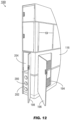
- the transformable monument 100 has an upper portion or section 112, a middle portion or section 114 directly below the upper section, and a lower portion or section 116 directly below the middle section.
- the upper section 112 may extend from approximately eye level to the ceiling (or the bulkhead 110) of the aircraft 104, while the lower section 116 may extend from approximately waist level to the floor of the passenger cabin.
- the upper section 112 may include storage compartments for crew equipment or passenger amenities, accessible on the inboard side (e.g., facing an aisle of the aircraft) via an inboard-side door 112a.
- the single-aisle aircraft 104a and twin-aisle aircraft 104b may be implemented and may function similarly to the aircraft 104 of FIG. 1 , except that the aircraft 104a-b may maximize the efficient use of limited interior space by positioning the transformable monument 100 in otherwise unused or underused cross-aisles 106 immediately proximate to exit doors (102, FIG. 1 ).
- the twin-aisle aircraft 104b may additionally implement the transformable monument 100 in class division spaces 106a where, e.g., premium seats may be bounded or otherwise separated from economy-class seats.
- the aircraft 104c and transformable monuments 100a-c may be implemented and may function similarly to the aircraft 104a-b of FIGS. 2A and 2B and the transformable monument 100 of FIG. 1 , except that the transformable monument 100a, which, however, is an illustrative example not being part of the current invention shows an extendable section 118 that extends into the cross-aisle 106, e.g., substantially parallel to the longitudinal or roll axis of the aircraft 104c, to create a temporary space within the cross-aisle and at least partially obstruct the exit door 102 from unauthorized passenger access.
- the extendable section 118 may extend partially, or fully, across the cross-aisle 106 and may extend from either or both of the lower section (116, FIG. 1 ), the middle section (114, FIG. 1 ), or the upper section (112, FIG. 1 ) individually or collectively.
- transformable monument 100b which, however, is an illustrative example not being part of the current invention, may be implemented and may function similarly to the transformable monument 100a, except that the transformable monument 100b incorporates a pivoting section 120 configured to pivot or unfold into the cross-aisle 106, e.g., relative to a horizontal pivotal or rotational axis substantially parallel to the lateral or pitch axis of the aircraft 104c, to create the temporary space.
- a transformable monument 100c which is an illustrative example not being part of the present invention may be implemented and may function similarly to the transformable monument 100b, except that the pivoting section 120 of the transformable monument 100b pivots into the cross-aisle relative to a vertical pivotal or rotational axis substantially parallel to the z-axis or yaw axis of the aircraft 104c.
- a transformable monument system 100d may be implemented and may function similarly to the transformable monument 100c of FIG. 2C , except that the transformable monument system 100d incorporates a pair of transformable monuments 100c on either side of the cross-aisle 106.
- Each transformable monument 100c incorporates a pivoting section (122a-b) that pivots into the cross-aisle 106, the pivoting sections 122a-b collectively creating the temporary space and obstructing the exit door 102.
- a transformable monument system 100e may be implemented and may function similarly to the transformable monument system 100d, transformable monument system 100e, which is an illustrative example not being part of the current invention.
- the transformable monument system 100e incorporates a pair of transformable monuments 100a on either side of the cross-aisle 106b, the extendable sections 118a-b of each transformable monument 100a extending into the cross-aisle 106 to create the temporary space and obstruct the exit door 102.
- the transformable monument 100 which, which is an illustrative example not being part of the current invention, may be implemented and may function similarly to the transformable monument 100a of FIG. 2C , except that the transformable monument 100f may include in its lower portion 116 an endcap 122 as well as upper and lower table leaves 124, 126 capable of deploying into the cross-aisle 106 to create a multi-level temporary work surface for cabin crew.
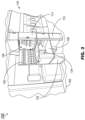
- the middle portion 114 of the transformable monument 100f may include a self-service compartment 128 for the storage of refreshments 130 accessible by cabin crew (e.g., for passenger catering) or accessible by the passengers themselves (e.g., once the aircraft 104 has reached safe cruising altitude).
- the transformable monument 100g which, which is an illustrative example not being part of the current invention, may be implemented and may function similarly to the transformable monument 100f of FIG. 3 , except that the upper and lower table leaves 124, 126 of the transformable monument 100g may be deployed by an exterior latch 132 in the endcap 122 of the lower portion 116.
- the transformable monument 100g may remain locked in a default or closed configuration, e.g., as shown by the transformable monument 100 of FIG. 1 .
- the exterior latch 132 may be configured for actuation by a single hand, e.g., the left or right hand of a cabin crewmember. By pulling upward on the exterior latch 132, the locking mechanism for the upper and lower table leaves 124, 126 may be released.
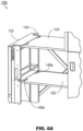
- the transformable monument 100h which, is an illustrative example not being part of the current invention, may be implemented and may function similarly to the transformable monument 100g of FIG. 4A , except that the upper and lower table leaves 124, 126 of the transformable monument 100h, once unlocked by the actuation of the exterior latch 132, may track upward and outward (e.g., in a longitudinal or forward direction substantially parallel with the roll axis of the aircraft 104, into the cross-aisle (106, FIG. 3 )) and into the deployed position shown by FIG. 4B .
- the upper and lower table leaves 124, 126 may lock into the deployed position for use as temporary work surfaces.
- a crewmember may similarly unlock the upper and lower table leaves 124, 126 by pulling upward with a single hand on the exterior latch 132 and pushing inward, folding the upper and lower table leaves back into the closed position shown by FIG. 1 .
- the deployment of the upper and lower table leaves 124, 126 may be assisted, and the deployed position of the upper and lower table leaves may be stabilized, by a crosslink system 134 on the outboard side of the transformable monument 100h.
- the crosslink system 134 may link the endcap 122 to an outboard track plate 136 inside the lower portion 116, pivoting and expanding as the upper and lower table leaves 124, 126 deploy.
- the endcap 122 may include additional auxiliary storage accessible via an auxiliary storage door 138 that opens into the cross-aisle 106.
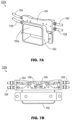
- the transformable monument 100i which, is an illustrative example not being part part of the current invention, may be implemented and may function similarly to the transformable monument 100h of FIG. 4B , except that the upper and lower table leaves 124, 126 may be pivotably attached to the endcap 122 by rotary latches 140 configured to lock the upper and lower table leaves in the default closed position (e.g., as shown by FIG. 1 ) until actuation of the exterior latch 132.
- the upper and lower table leaves 124, 126 may be connected to the endcap 122 by the rotary latches 140 at their forward ends 124a, 126a (e.g., proximate to the exit door (102, FIG.
- the rotary latches 140 allow the forward ends 124a, 126a of the upper and lower table leaves 124, 126 to pivot in place relative to the endcap 122 as the tail ends 124b, 126b of the upper and lower table leaves translate upward and the upper and lower table leaves deploy.
- the lower portion 116 of the transformable monument 100i may include track plates 136 on both the inboard and outboard sides of the upper and lower table leaves 124, 126.
- Tracks 142, 144 may be machined into each track plate 136; the tail ends 124b, 126b of the upper and lower table leaves 124, 126 may track generally upward and outward toward a substantially horizontal terminal section 146 for supporting the table leaves in the deployed position.
- the tail end 124b of the upper table leaf 124 and the tail end 126b of the lower table leaf 126 may include leaf latches 148a-b incorporating sleeve bearings 150, 152 that track upward and downward along the tracks 142, 144 set into the track plates 136.
- the sleeve bearing 150 of the upper table leaf 124 may incorporate a spring-loaded locking pin 154.
- the spring-loaded locking pin 154 may extend into a hole or slot (not shown) in the track plate 136, locking the upper and lower table leaves into the deployed position.
- the deployment of the upper and lower table leaves 124, 126 may be further assisted by a cable retractor 156 (e.g., a 5-pound constantforce cable retractor) and tensioned cable 158 operating independently of the exterior latch 132.
- the leaf latch 148a attached to the tail end 124a of the upper table leaf 124 may include the cable retractor 156, which may be connected to the track plate 136 by the tensioned cable 158. By pulling on the tensioned cable 158, the cable retractor 156 may assist the upper and lower table leaves 124, 126 in deploying from the default closed position (shown by FIG. 1 ) to the fully deployed position (shown by FIG. 4B ).
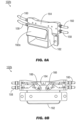
- the transformable monument 100j which, is an illustrative example not being part of the current invention, may be implemented and may function similarly to the transformable monument 100i of FIG. 5A , except that the lower table leaf 126 of the transformable monument 100j may be pivotably connected to the endcap 122 by rotary latches 140a.
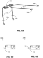
- the rotary latches 140a may be linked to the exterior latch 132 by rotary latch cables 158.
- the exterior latch 132 may be linked to the leaf latches 148a of the upper table leaf 124 by leaf latch cables 160. Actuating the exterior latch 132 may pull the rotary latch cables 158 and leaf latch cables 160, unlocking the rotary latches 140a and leaf latches 148a and unlocking the upper and lower table leaves 124, 126 from the default closed position, allowing the upper and lower table leaves to be deployed.
- the leaf latch 148c may be implemented and may function similarly to the leaf latches 148a of FIG. 6B , except that the leaf latch 148c may be in an open position, allowing the upper and lower table leaves 124, 126 ( FIG. 6A ) to deploy.
- the leaf latch 148d may be implemented and may function similarly to the leaf latch 148c of FIG. 6C , except that when the endcap 122 ( FIG.
- the spring-loaded pin 154 may extend from the sleeve bearing 150 and into the corresponding hole in the track plate (136, FIG. 5A ), locking the upper and lower table leaves 124, 126 into the deployed open position (shown by FIG. 4B ).
- the exterior latch 132a may be implemented and may function similarly to the exterior latch 132 of FIG. 6B , except that the exterior latch 132a may include a handle assembly 162 and cable actuator 164.
- the handle assembly 162 (including the handle 162a) may be mounted on the exterior face of the endcap 122 (see also, e.g., FIG. 5A ) while the cable actuator 164 may be mounted inside the endcap 122 directly opposite the handle assembly.
- the rotary latch cables 158 and leaf latch cables 160 may terminate at the cable actuator 164.
- Torsion springs (not shown) may hold the cable actuator 164 in the default, closed position while the exterior latch 132a remains unactuated.
- the exterior latch 132b may be implemented and may function similarly to the exterior latch 132a of FIGS. 7A /B, except that the exterior latch 132b may be deployed by a cabin crewmember by pulling upward the handle 162a with either hand. Pulling up the handle 162a causes rockers 166 in the cable actuator 164 to be pulled downward, simultaneously pulling all four of the rotary latch cables 158 and leaf latch cables 160 and unlocking the upper and lower table leaves 124, 126 ( FIG. 6A ) for deployment to the open deployed position.
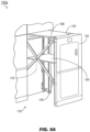
- the crosslink system 134a may be implemented and may function similarly to the crosslink system 134 of FIG. 4B , except that the crosslink system 134a may include two crossing members 168, 170 centrally linked by a pivot pin 172 or similar mechanism at their midpoints (e.g., through holes or openings at the midpoint of each crossing member).
- the crosslink system 134a may be implemented on the outboard side (e.g., facing the exit door (102, FIG. 1 )) of the lower portion 116 of the transformable monument (100, FIG. 1 ) to stabilize the upper and lower table leaves 124, 126 in the open and deployed position.
- the crossing member 168 may pivotably connect the interior of the endcap 122 (proximate to the upper table leaf 124 and the outboard rotary latch 140) to the outboard track plate (136, FIG. 4B ) while the crossing member 170 may pivotably connect the outboard track plate 136 (proximate to the upper table leaf 124 and the outboard leaf latch 148a ( FIG. 5B )) to the interior of the endcap 122 below its connection point to the crossing member 168.
- the crossing members 168, 170 may each, at their lower points of connection with the outboard track plate 136 and the endcap 122 respectively, track within substantially vertical linear guides 174, 176.
- the crossing members 168, 170 may be fully extended (e.g., wherein the vertical angle 178 between the crossing members reaches its maximum) and their points of connection may reach the high terminal points (174a, 176a) of the linear guides 174, 176.
- the linear guides 174, 176 may prevent the crossing members 168, 170 from extending any further and help to stabilize the upper and lower table leaves 124, 126 in the fully deployed position.
- the crosslink system 134b may be implemented and may function similarly to the crosslink system 134a of FIG. 9B , except that when the upper and lower table leaves 124, 126 are unlocked from the open, fully deployed positions and retracted back into the lower portion 116, the crossing members 168, 170 may track downward in the linear guides 174, 176 until reaching the low terminal points 174b, 176b, at which point the horizontal angle 178a between the crossing members 166, 170 may reach its maximum and the upper and lower table leaves 124, 126 are locked into the default, closed position.
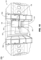
- the self-service compartment 128a may be implemented and may function similarly to the self-service compartment 128 of FIG. 3 , except that the self-service compartment 128a includes edge lighting elements 180, interior lighting 182, inventory sensors 182, and a camera 184.
- edge lighting elements 180 may demarcate the boundaries of the middle portion 114 of the transformable monument (100, FIG. 1 ) with respect to the upper portion 112 and lower portion 116.
- the edge lighting elements 180 may be connected to an aircraft network controller to be activated, deactivated, or adjusted based on command input entered by a cabin crewmember, or due to other predetermined or preprogrammed factors.
- the edge lighting elements 180 in concert with other cabin lighting, may be dimmed or brightened, or its output spectrally shifted, based on the current time or on a current flight segment.
- Interior lighting 182 may illuminate the contents of the self-service compartment 128a, activating when the door 188 of the self-service compartment is opened.
- the self-service compartment 128a may be a room-temperature compartment for the storage of refreshments 130 at or near the ambient cabin temperature, or the self-service compartment may be equipped with a chiller (e.g., air-cooled or conductive chiller) or heating element (not shown) for regulating the storage temperature of the refreshments 130.
- a chiller e.g., air-cooled or conductive chiller
- heating element not shown
- the interior lighting 182 may be powered by the aircraft power system (e.g., as a galley insert (GAIN)) and connected to a galley network controller (GNC) or other aircraft controller configured to adjust the output of the interior lighting based on the contents or status of the self-service compartment 128a.
- the interior lighting 182 may be tinted blue to indicate a chiller compartment, tinted red to indicate a warmer compartment, flashed or blinked to instruct passengers to return to their seats, or dimmed to indicate a compartment that is nearly or fully empty.
- Cabin crewmembers may use the self-service compartment 128a to dispense refreshments 130 to passengers throughout the course of catering and service operations.
- passengers may (during the appropriate flight segments, e.g., at a safe cruising altitude) use the cross-aisle (106, FIG. 1 ) immediately proximate to the transformable monument 100 as a congregational or social area (e.g., provided the extendable portion (118, FIG. 2C ) in the lower portion 116 is not deployed) and selfserve refreshments 130 from the self-service compartment 128a.
- a congregational or social area e.g., provided the extendable portion (118, FIG. 2C ) in the lower portion 116 is not deployed
- the interior shelves and compartments 190 of the self-service compartment 128a may include inventory sensors 184 for determining when a refreshment item 130 has been removed from the shelf, e.g., by a change in weight or pressure.
- the inventory sensors 184 may thus track the inventory of each self-service compartment 128a (e.g., by forwarding inventory tracking information to an aircraft network or galley network controller) or alert cabin crew to shortages of any particular item (e.g., by messaging a mobile communications or computing device carried by a crewmember).
- the camera 186 may activate whenever a removal is detected by the inventory sensors 184; for example, if a passenger removes a refreshment item 130 the camera may capture one or more images in response to the detected removal, and forward the images to an aircraft network controller or other like control processor for analysis of the image.
- the network controller may attempt to positively identify the passenger via image recognition (e.g., facial recognition, comparison to a reference image, or detection of a QR code or similar visually encoded data held or worn by the passenger to facilitate use of the self-service compartment 128a) so that the correct passenger may be charged for any refreshment items 130 removed from the self-service compartment.
- image recognition e.g., facial recognition, comparison to a reference image, or detection of a QR code or similar visually encoded data held or worn by the passenger to facilitate use of the self-service compartment 128a
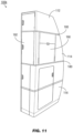
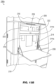
- a transformable monument 100k which, however, is an illustrative example not being part of the current invention, may be implemented and may function similarly to the transformable monument 100b of FIG. 2C , except that the transformable monument 100k may include, within its middle portion 114, a multipurpose panel 190 set into the inward side (e.g., the side proximate the cross-aisle (106, FIG. 1 )).
- the multipurpose panel 190 may be implemented and may function similarly to the pivoting portion 120 of FIG.
- the multipurpose panel 190 may reveal, within the middle portion 114, inboard-accessible storage (e.g., through a door 192 opening into the cross-aisle) for crew equipment or two standard units (SU). It is contemplated that the multipurpose panel 190 may have an overall thickness of no more than 1.5 inches, such that the multipurpose panel may be integrated into a new transforming monument 100k or retrofitted into an existing monument. Similarly to the transformable monuments shown by, e.g., FIGS.
- the transformable monument 100k may include edge lighting elements 180 demarcating the upper portion 112, the middle portion 114, and the lower portion 116; the edge lighting elements 180 may be communicatively linked to an aircraft network controller configured to activate, deactivate, dim, brighten, or shift the luminous output of the edge lighting elements in concert with other cabin lighting, e.g., based on the current time or current flight segment.
- a multipurpose station (transformable) monument 100l which, however, is an illustrative example not being part of the current invention, may be implemented and may function similarly to the transformable monument 100k of FIG. 11 , except that the transformable monument 100l may include, within its lower portion 116, longitudinally-accessible storage 194 (e.g., through a door 196 opening in a forward or aft direction) for crew equipment or passenger amenities as well as inboard-accessible storage (e.g., through a door 198 opening into the aisle) for oxygen containers 200 (e.g., in the lowermost lower portion 202) and crew equipment (e.g., in the uppermost lower portion 204).
- longitudinally-accessible storage 194 e.g., through a door 196 opening in a forward or aft direction
- inboard-accessible storage e.g., through a door 198 opening into the aisle
- oxygen containers 200 e.g., in the lowermost lower portion 202
- crew equipment e.
- the middle portion 114a may be implemented and may function similar to the middle portion 114 of the transformable monument 100l of FIG. 11 , except that the middle portion 114a may include a multipurpose panel 190 divided into a charging-compartment cover 206 and a deployable surface 208 covering substantially the top third and the bottom two-thirds respectively of the multipurpose panel 190.
- the middle portion 114a may include deployable hooks 210 on either side of the multipurpose panel 190; the deployable hooks 210 may be magnetically secured into place until deployed by pressing on the upper end.
- the multipurpose panel 190 may be deployed, e.g., by pressing on the exterior latch 212, e.g., with a single hand.
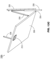
- the multipurpose panel 190a may be implemented and may function similar to the multipurpose panel 190 of FIG. 13A , except that upon deployment (e.g., by pressing the exterior latch 212 ( FIG. 13A )), the charging-compartment cover 206 of the multipurpose panel 190a may pivot upward, and the deployable surface 208 may deploy downward, into a substantially horizontal work surface of c. 500 in2.
- the deployable surface 208 may deploy downward to reveal a note holder 214 to which notes 216 or small sheets of paper may be secured in place (e.g., by pressing a lower portion 214a backwards to secure the note between the lower portion and an upper portion 214b).
- the deployable hooks 210 may, in their deployed state, be used to secure trash bags or other objects.
- the charging-compartment cover 206 may pivot upward to reveal a downward-oriented work light 218 and a charging compartment 220 configured to wirelessly and inductively charge any suitably equipped mobile devices (222; e.g., smartphones, tablets) placed therein.
- the multipurpose panel 190b may be implemented and may function similarly to the multipurpose panel 190a of FIG. 13B , except that the multipurpose panel 190b may include a damping system.
- the damping system allows the deployable surface 208 to deploy downward at a consistent and regulated rate, providing for single-hand deployment of the multipurpose panel 190b (e.g., via the exterior latch 212).
- the deployable surface 208 may be connected to the multipurpose panel 190b by fixed pivot points 224 and support struts 226 which translate upward or downward along a table strut track 228 as the deployable surface 208 is opened or closed.
- the support struts 226 may track downward along the table strut track 228, the tracking speed of the support struts (and the speed with which the deployable surface opens) regulated by the compression of a gas spring (230) or like damper.
- the charging compartment 220a may be implemented and may function similarly to the charging compartment 220 of FIG. 13B , except that the charging compartment 220a may include a pocket 232 for securing any mobile devices (222, FIG. 13B ) placed therein and a wireless inductive charger 234 embedded within the rear panel 236 of the charging compartment.
- the charging compartment 220b may be implemented and may function similarly to the charging compartment 220a of FIG. 14A , except that the charging compartment 220b may include USB ports 238 or other like charging or connection ports for connecting mobile devices 222 incapable of wireless or inductive charging.
- the USB ports 238 may be situated within a side interior panel of the charging compartment 220b, behind the pocket 232 and the rear panel 236.
- the transformable monument system 100m may be implemented and may function similarly to the transformable monument systems 100d-e of FIG. 2D , except that the transformable monument system 100m incorporates left-side and right-side transformable monuments 100c on either side of the exit door 102, creating a temporary socialization or entertainment area within the cross-aisle 106 proximate to the exit door.
- the transformable monument system 100m incorporates (on either the left or the right side) any combination of the left-side and right-side transformable monuments 100c on either side of the cross-aisle 106.
- the transformable monument system 100m may be more commonly implemented in larger cross-aisles 106 associated with larger twin-aisle aircraft (104b, FIG. 2B ). Both the left-side and right-side monuments 100c may separate the cross-aisle 106 from seating areas 108 of the aircraft 104. Generally the left-side and right-side transformable monuments 100c may be similar or identical with respect to the components of their upper portions 112, middle portions 114, and lower portions 116. Either the left-side or right-side transformable monument 100c may include an attendant seat 240 mounted to an inside panel; the attendant seat 240 may fold down for temporary use by cabin crew, e.g., during takeoff, climb, descent, and landing segments. The attendant seat 240 mounted to the right-side monument 100c may provide added structural stability to the right-side transformable monument when converted into the open configuration described below.
- the transformable monument system 100n may be implemented and may function similarly to the transformable monument system 100m of FIG. 15
- the inside exterior panels 242 of the left-side and right-side transformable monuments 100c may be implemented and may function similarly to the pivoting portions 122a-b of FIG. 2D , except that the inside exterior panels 242 may pivot open to reveal literature compartments 244, self-service compartments 128 within which refreshments 130 may be stored for passenger selection, or fold-out ledges (246) for temporary placement of refreshments.
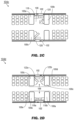
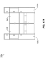
- FIGS. 17A and 17B an embodiment of a transformable monument system 100p according to the present invention is shown, the transformable monument system 100p may be implemented and may function similarly to the transformable monument system 100n of FIG. 16 , except that the left-side and right-side monuments 100c of the transformable monument system 100p fully extend their inside exterior panels 242 to create a temporary passenger destination space within the cross-aisle 106, obscuring the exit door 102.
- the left-side and right-side inside exterior panels 242 may not interconnect or physically link to each other when in the open configuration; rather, each inside exterior panel may pivot into its open configuration (e.g., through an angle of at least 90 degrees) and secure via locking ball detent latches (not shown) or other like means of independently weighing or loading each inside exterior panel for increased structural stability and resistance to vibration or rattling.
- the inside exterior panels 242 may each pivot open substantially 90 degrees inward 248 while translating in an outboard direction.
- Pivot arms (250) connect the outboard side of the exterior panels 242 to their respective transformable monuments 100c via fixed pivot points 250a-b at either end of the pivot arms.
- the right-side exterior panel 242 may pivot around the door pivot point 250a while the pivot arm 250 pivots around the fixed pivot point 250b relative to the right-side transformable monument 100c.
- the fold-out ledge 246 may include a base246a and a leaf 246b that folds over from the base 312a when the inside exterior panels 308a-b have fully pivoted into their open configuration.
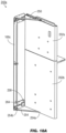
- FIGS. 18A and 18B an embodiment of a transformable monument system 100 according to the present invention is shown, the exterior panel 242a of which may be implemented and may function similarly to the left-side and right-side exterior panels 242 of FIGS. 17A-B , except that the exterior panel 242a may include upper and lower partitions 252a-b corresponding to the middle and lower portions 114, 116 ( FIG. 15 ) of the corresponding right-side transformable monument 100c.
- the exterior panel 242a may be mounted to the right-side transformable monument 100c by an upper pivot arm 250 and a lower pivot arm 254, both pivot arms extending from fixed pivot points 250b, 254b to door pivot points 250a, 254a.
- the exterior panel 242a may further be connected to the right-side transformable monument 100c by an upper hinge 256 and a lower hinge 258, the upper and lower hinges operating in concert with the pivot arms 250, 254 as the exterior panel 242a pivots into the open configuration (as shown by FIGS. 17A-B ).
- the upper and lower hinges 256, 258 translate outboard (260) with the exterior panel along upper and lower hinge slides 262, 264.
- the exterior panel 242a is converted back into the closed, default configuration (as shown by FIG. 15 )
- the upper and lower hinges 256, 258 translate inboard along the hinge slides 262, 264 with the exterior panel.
- the transformable monument system 100q may be implemented and may function similarly to the transformable monument system 100p of FIGS. 17A-B , except that the transformable monument system 100q may include auxiliary lighting elements 266 and fold-out shelves 246 for temporary placement of beverages or other refreshments 130, e.g., available in a self-service compartment 128 of the transformable monument system 100q.
- the fold-out shelves 246 may be partially or fully stored within a slot 268 within the transformable monument 100c while the transformable monument system 100q is in the default, closed configuration (as shown by FIG. 15 ).
- the fold-out shelf 246 may include a base portion 246a and a leaf portion 246b; when the transformable monument system 100q is in the open configuration, the leaf portion 246b may be folded over from the base portion 246a to fully extend the fold-out shelf 246.
- the auxiliary lighting elements 266 may be connected to an aircraft network controller for central control of the activation, deactivation, or dimming of the lighting elements, or the auxiliary lighting elements may be activated by the conversion of the transformable monument system 100q to the open configuration (e.g., similarly to the interior lighting (182, FIG. 10 ) of the self-service compartment 128).
- the fold-out shelf 246c of an embodiment of a transformable monument system 100q according to the present invention is shown, that may be implemented and may function similarly to the fold-out shelf 246 of FIG. 19 , except that the fold-out shelf 246c may include power cabling for the auxiliary lighting elements (266, FIG. 19 ) within the base section 246a and leaf section 246b.
- the base section 246a and leaf section 246b may be connected by invisible hinges 270 that disappear from view as the leaf section 246b is folded over to fully extend the foldout shelf 246c.
- the base section 246a and leaf section 246b may additionally conceal a Reed switch 272 or like magnetic switching means connected to the power cabling, such that when the leaf section 246b is folded over, the switch circuit completes and the auxiliary lighting elements 266 are activated (and again deactivated when the leaf section is folded back onto the base section).
Landscapes
- Engineering & Computer Science (AREA)
- Aviation & Aerospace Engineering (AREA)
- Aiming, Guidance, Guns With A Light Source, Armor, Camouflage, And Targets (AREA)
- Cabinets, Racks, Or The Like Of Rigid Construction (AREA)
- Tires In General (AREA)
Claims (11)
- Aéronef comprenant une cabine passagers, une porte de sortie (102), une allée transversale (106) s'étendant latéralement à travers l'aéronef depuis la porte de sortie (102) de l'aéronef (104) et un système de monuments (100d), le système de monuments (100d) comprenant une paire de monuments avec un premier (100c) et un second monument (100c) positionnés entre un plancher et un plafond (110) de la cabine passagers et à proximité de la porte de sortie (102) et de l'allée transversale (106) de l'aéronef (104),le premier monument (100c) ayant un côté intérieur adjacent à l'allée transversale (106) et un côté extérieur opposé au côté intérieur,le premier monument (100c) ayant en outre une section pivotante (120) configurée pour pivoter dans l'allée transversale par rapport à un axe de pivotement ou de rotation vertical sensiblement parallèle à l'axe z ou à l'axe de lacet de l'aéronef (104c) créant l'espace fonctionnel temporaire à travers l'allée transversale et obstruant la porte de sortie (102),le premier monument (100c) ayant une partie supérieure (112) adjacente au plafond (110), une partie inférieure (116) adjacente au plancher, et au moins une partie médiane (114) entre la partie supérieure (112) et la partie inférieure (116),dans lequel le premier monument (100c) est un monument multimode transformable (110c), au moins l'une parmi la partie médiane (114) et la partie inférieure (116) comprenant une partie de transformation configurée pour définir un espace fonctionnel à travers l'allée transversale (106) en pivotant de manière réversible depuis le côté interne par rapport à un axe de rotation de l'état replié à l'état déployé,caractérisé en ce que le système de monuments (100d) comprend la paire de monuments (100c) de chaque côté de l'allée transversale (106), chacun du premier monument (100c) et du second monument (100c) incorporant une section pivotante (120a, 120b) qui pivote dans l'allée transversale (106), les sections pivotantes (120a, 120b) créant collectivement l'espace fonctionnel temporaire à travers l'allée transversale et obstruant la porte de sortie (102), eten ce que le premier monument (100c) a un premier côté intérieur et la partie de transformation est configurée pour définir l'espace fonctionnel à travers l'allée transversale (106) en collaboration avec le second monument (100c), le second monument (100c) ayant un second côté intérieur opposé au premier côté intérieur.
- Aéronef selon la revendication 1, dans lequel la partie de transformation est configurée pour obstruer au moins partiellement la porte de sortie (102).
- Aéronef selon une ou plusieurs des revendications 1 et 2 et comprenant une partie de transformation, dans lequel la seconde partie de transformation comprend au moins une deuxième surface déployable configurée pour pivoter par rapport à un axe de rotation sensiblement horizontal, dans lequel la seconde partie de transformation comprend en outre de préférence au moins un premier compartiment de stockage disposé derrière la deuxième surface déployable, dans lequel le premier compartiment de stockage (128) comprend en outre de préférence au moins l'un parmi :un port de connexion pouvant être couplé à un dispositif électronique portable (PED) ; etun chargeur sans fil configuré pour charger par induction le PED.
- Aéronef selon une ou plusieurs des revendications 1 à 3, dans lequel au moins un siège déployable (240) est attaché au côté intérieur, le siège déployable (240) est capable d'accueillir un membre d'équipage lorsque la partie de transformation est en position repliée.
- Aéronef selon une ou plusieurs des revendications 1 à 4, dans lequel la partie de transformation peut être actionnée de l'état replié à l'état déployé par l'intermédiaire d'un loquet externe (132) configuré pour être actionné par une seule main.
- Aéronef selon une ou plusieurs des revendications 1 à 5, comprenant en outre :
au moins un second compartiment de stockage (128a) accessible depuis l'espace fonctionnel à travers l'allée transversale lorsque la partie de transformation est à l'état déployé. - Aéronef selon la revendication 6, dans lequel le second compartiment de stockage (128a) est accessible via au moins une porte (188), comprenant en outre :
au moins un capteur d'inventaire (184) disposé à l'intérieur du second compartiment de stockage (128a), le capteur d'inventaire étant configuré pour détecter le retrait d'un article stocké dans le second compartiment de stockage. - Aéronef selon la revendication 7, dans lequel le capteur d'inventaire (184) comprend un appareil photo (186) couplé en communication à un réseau de l'aéronef (104), l'appareil photo (186) étant configuré pour :capturer au moins une image correspondant au retrait ; ettransmettre l'image capturée au réseau.
- Aéronef selon une ou plusieurs des revendications 1 à 8, comprenant en outre :
au moins un élément d'éclairage de bord (180) qui est couplé en communication à un réseau de l'aéronef (104), l'élément d'éclairage de bord (180) étant capable de générer une sortie lumineuse et configuré pour effectuer au moins l'un parmi l'activation, la désactivation et le réglage de la sortie lumineuse sur la base d'un ou de plusieurs parmi une heure, un segment de vol et une entrée d'instruction fourni(e) au réseau par un membre d'équipage. - Aéronef selon une ou plusieurs des revendications 1 à 9, lorsqu'elles dépendent de la revendication 3,
dans lequel la seconde partie de transformation comprend au moins une troisième surface déployable configurée pour pivoter par rapport à un axe de rotation sensiblement vertical. - Aéronef selon une ou plusieurs des revendications 1 à 10, lorsqu'elles dépendent de la revendication 3,
dans lequel la seconde partie de transformation comprend au moins un loquet de verrouillage configuré pour fixer la seconde partie de transformation à un ou plusieurs parmi le plancher, le premier monument et le second monument.
Applications Claiming Priority (2)
| Application Number | Priority Date | Filing Date | Title |
|---|---|---|---|
| US201815950089A | 2018-04-10 | 2018-04-10 | |
| US16/030,586 US11124299B2 (en) | 2018-04-10 | 2018-07-09 | Multi-mode transformable monuments for aircraft doorway spaces |
Publications (2)
| Publication Number | Publication Date |
|---|---|
| EP3552963A1 EP3552963A1 (fr) | 2019-10-16 |
| EP3552963B1 true EP3552963B1 (fr) | 2024-07-31 |
Family
ID=66102531
Family Applications (1)
| Application Number | Title | Priority Date | Filing Date |
|---|---|---|---|
| EP19167878.8A Active EP3552963B1 (fr) | 2018-04-10 | 2019-04-08 | Monuments multimode transformables pour espaces de porte d'aéronef |
Country Status (3)
| Country | Link |
|---|---|
| US (1) | US11124299B2 (fr) |
| EP (1) | EP3552963B1 (fr) |
| CN (1) | CN110356560B (fr) |
Families Citing this family (27)
| Publication number | Priority date | Publication date | Assignee | Title |
|---|---|---|---|---|
| US11919643B2 (en) * | 2018-04-10 | 2024-03-05 | Rockwell Collins, Inc. | Self-deploying counter for multimode transformable monuments |
| US11377213B2 (en) | 2018-05-02 | 2022-07-05 | B/E Aerospace, Inc. | Modular lavatory accessible to passengers of reduced mobility (PRM) |
| DE102018127044A1 (de) * | 2018-10-30 | 2020-04-30 | Airbus Operations Gmbh | Verkleidungsbauteil für eine Kabine eines Transportmittels |
| DE102019002501B4 (de) * | 2019-04-05 | 2023-03-16 | Diehl Aviation Laupheim Gmbh | Kabinensegment mit Freiraum |
| US11130575B2 (en) | 2019-05-10 | 2021-09-28 | B/E Aerospace, Inc. | Slim aircraft monument with deployable workstation |
| USD945855S1 (en) * | 2019-06-06 | 2022-03-15 | B/E Aerospace, Inc. | Push button latch assembly |
| US11027846B2 (en) * | 2019-08-27 | 2021-06-08 | B/E Aerospace, Inc. | Stowable door folding table |
| US11548640B2 (en) * | 2019-11-19 | 2023-01-10 | B/E Aerospace, Inc. | Compartment content notification and inspection device and method |
| US11623748B2 (en) | 2020-02-26 | 2023-04-11 | B/E Aerospace, Inc. | Galley slide out utensil drawer and message center |
| US11643210B2 (en) * | 2020-03-27 | 2023-05-09 | B/E Aerospace, Inc. | Flexible bar and shop space for aircraft cabin |
| US11572170B2 (en) * | 2020-07-21 | 2023-02-07 | B/E Aerospace, Inc. | Aircraft interior structure including actuatable panels and a footwell |
| EP4005923B1 (fr) | 2020-11-30 | 2023-08-30 | Bucher Leichtbau AG | Station de ravitaillement embarquée |
| JP7157834B2 (ja) * | 2021-01-29 | 2022-10-20 | 本田技研工業株式会社 | 乗物用シート |
| JP7242723B2 (ja) * | 2021-01-29 | 2023-03-20 | 本田技研工業株式会社 | 乗物用シート |
| US20220388660A1 (en) * | 2021-06-04 | 2022-12-08 | The Boeing Company | Resting area systems for an internal cabin of a vehicle |
| EP4113492A1 (fr) | 2021-06-28 | 2023-01-04 | B/E Aerospace, Inc. | Affichage réglable |
| EP4140885B1 (fr) | 2021-08-24 | 2023-10-04 | Airbus Operations GmbH | Récipient d'oxygène mobile et monument, section de véhicule de passager et véhicule le comportant |
| EP4183684A1 (fr) * | 2021-11-20 | 2023-05-24 | B/E Aerospace, Inc. | Postes de travail embarqués pour aéronef |
| US11918117B2 (en) | 2022-05-18 | 2024-03-05 | B/E Aerospace, Inc. | Convertible closet with articulating top shelf |
| US12208904B2 (en) | 2022-08-09 | 2025-01-28 | B/E Aerospace, Inc. | Split cabin attendant seat |
| USD1062581S1 (en) * | 2023-02-02 | 2025-02-18 | Textron Innovations Inc. | Aircraft galley |
| US12312097B2 (en) | 2023-06-16 | 2025-05-27 | The Boeing Company | Hybrid barrier for aircraft cabin |
| US12291351B2 (en) * | 2023-06-16 | 2025-05-06 | The Boeing Company | Deployable attendant seat aircraft cabin barrier |
| US12227282B2 (en) | 2023-06-16 | 2025-02-18 | The Boeing Company | Barrier door for an aircraft |
| US12534179B2 (en) | 2023-06-16 | 2026-01-27 | The Boeing Company | Barrier door for an aircraft |
| EP4527738A1 (fr) * | 2023-09-19 | 2025-03-26 | B/E Aerospace (UK) Limited | Étagère de cuisine |
| US20250091717A1 (en) * | 2023-09-20 | 2025-03-20 | Textron Aviation Inc. | Adjustable Pocket for Aircraft Sidewall |
Citations (2)
| Publication number | Priority date | Publication date | Assignee | Title |
|---|---|---|---|---|
| US20070035919A1 (en) * | 2003-02-24 | 2007-02-15 | Airbus Deutschland Gmbh | Modular communication fixture for installation on board of a passenger conveyance |
| US20140373759A1 (en) * | 2013-06-19 | 2014-12-25 | Airbus (Sas) | Folding table system with removable extension and rigidification element, and aircraft including such a system |
Family Cites Families (104)
| Publication number | Priority date | Publication date | Assignee | Title |
|---|---|---|---|---|
| US2763900A (en) * | 1954-06-14 | 1956-09-25 | Boeing Co | Door for pressurized aircraft |
| US2854307A (en) * | 1954-11-26 | 1958-09-30 | Archibald D Londeree | Power elevated cabinet |
| US3472219A (en) * | 1968-02-23 | 1969-10-14 | Coleman Co | Collapsible galley assembly for trailer |
| USRE32176E (en) * | 1968-04-04 | 1986-06-10 | Unitized aircraft food and beverage service | |
| US4022404A (en) * | 1975-10-22 | 1977-05-10 | The Boeing Company | Upper deck main galley in a three deck, wide-bodied passenger airplane |
| US4055317A (en) * | 1976-06-30 | 1977-10-25 | The Boeing Company | Aft main deck split level galley |
| GB1599821A (en) | 1977-03-01 | 1981-10-07 | Vega Manuf | Folding seat and table unit |
| US4361014A (en) * | 1981-03-19 | 1982-11-30 | Sundstrand Corporation | Panel air chiller |
| US4375876A (en) * | 1981-06-04 | 1983-03-08 | The Boeing Company | Overhead sliding door and foldable cabin panel assembly for an airplane |
| US4478467A (en) | 1982-12-27 | 1984-10-23 | Tyndall Howard W | Portable workshop |
| US4776903A (en) * | 1983-11-25 | 1988-10-11 | Nordskog Robert A | Method of fabricating a light weight plastic vehicular interior building construction |
| US5090639A (en) * | 1989-10-26 | 1992-02-25 | United Parcel Service General Services Co. | Cargo-carrying system for passenger aircraft |
| US5224297A (en) * | 1991-06-10 | 1993-07-06 | Nelson A. Taylor Co., Inc. | Sliding door and latching/locking assembly |
| US5322244A (en) * | 1992-03-17 | 1994-06-21 | Deutsche Aerospace Airbus Gmbh | Supply system for passenger aircraft |
| US6007025A (en) * | 1996-12-23 | 1999-12-28 | The Boeing Company | Stowable module airplane lavatory |
| US5907127A (en) * | 1997-08-29 | 1999-05-25 | Lucent Technologies Inc. | Enclosure for telecommunications applications having a configurable mounting plane |
| DE19956668B4 (de) * | 1999-11-25 | 2005-03-10 | Airbus Gmbh | Duscheinrichtung |
| US6257523B1 (en) * | 1999-12-09 | 2001-07-10 | The Boeing Company | Foldable partition with integral door |
| JP2001199399A (ja) * | 2000-01-20 | 2001-07-24 | Jamco Corp | 航空機用ギャレイユニット |
| JP2001204552A (ja) | 2000-01-31 | 2001-07-31 | Jamco Corp | 航空機用配膳車 |
| CA96186S (en) * | 2000-06-02 | 2003-03-24 | Fairchild Dornier Gmbh | Aircraft interior |
| US6646863B1 (en) | 2000-10-26 | 2003-11-11 | Neptune Networks, Inc. | Semi-private internet kiosk |
| US6691952B2 (en) * | 2001-09-26 | 2004-02-17 | Marvin Keogh | Aircraft medical unit |
| US20050116098A1 (en) * | 2002-01-09 | 2005-06-02 | Larry Martens | Flight deck security system |
| JP3719510B2 (ja) * | 2002-04-08 | 2005-11-24 | アルプス電気株式会社 | 非接触式充電器を有する保管庫 |
| NL1021107C2 (nl) * | 2002-07-18 | 2004-01-20 | Driessen Aircraft Holding B V | Modulaire kombuis voor in een vliegtuig of trein alsmede wand en module voor een dergelijke kombuis en daarmee uitgerust vliegtuig of trein. |
| US6761332B1 (en) * | 2003-04-01 | 2004-07-13 | The Boeing Company | Multi-functional galley system |
| JP4200073B2 (ja) * | 2003-09-29 | 2008-12-24 | 株式会社ジャムコ | 航空機用ギャレーの通信装置 |
| JP3970825B2 (ja) * | 2003-10-02 | 2007-09-05 | 株式会社ジャムコ | 航空機用ギャレー |
| US8005580B2 (en) * | 2003-12-09 | 2011-08-23 | The Boeing Company | Aircraft galley systems and methods for managing electric power for aircraft galley systems |
| US20050133308A1 (en) * | 2003-12-22 | 2005-06-23 | Reysa Gary D. | Galley cart storage system and method of use |
| US7080806B2 (en) * | 2004-03-26 | 2006-07-25 | The Boeing Company | Overhead space access conversion monument and service area staircase and stowage system |
| US7159821B2 (en) * | 2004-04-02 | 2007-01-09 | The Boeing Company | Integrated transport system for overhead stowage |
| JP2006069457A (ja) * | 2004-09-06 | 2006-03-16 | Jamco Corp | オーブン |
| US7494091B2 (en) * | 2005-02-22 | 2009-02-24 | The Boeing Company | Aircraft cart transport and stowage system |
| US7721797B2 (en) * | 2005-04-25 | 2010-05-25 | Be Intellectual Property, Inc. | Refrigerator-oven combination for an aircraft galley food service system |
| US20070102579A1 (en) * | 2005-09-13 | 2007-05-10 | Airbus Deutschland Gmbh | Modular structure |
| DE102005043610A1 (de) | 2005-09-13 | 2007-03-22 | Airbus Deutschland Gmbh | Modulares Monument |
| WO2007096000A1 (fr) * | 2006-02-24 | 2007-08-30 | Airbus Deutschland Gmbh | cambuse et procédé de RESTAURATION pour passagers dans un aéronef |
| US20070228216A1 (en) * | 2006-04-03 | 2007-10-04 | Be Aerospace, Inc. | Galley assembly for an aircraft |
| DE102006023047B4 (de) * | 2006-05-17 | 2010-01-14 | Airbus Deutschland Gmbh | Modulare Bordküche, insbesondere für ein Flugzeug |
| US7954761B2 (en) * | 2006-11-30 | 2011-06-07 | Be Aerospace, Inc. | Modular integrated galley |
| US20080150406A1 (en) * | 2006-12-20 | 2008-06-26 | Be Aerospace, Inc. | Galley unit including container handling mechanism |
| DE102007001806A1 (de) * | 2007-01-12 | 2008-07-17 | Airbus Deutschland Gmbh | Beschichtung einer Montageschiene |
| US20100140398A1 (en) * | 2007-02-19 | 2010-06-10 | Be Aerospace, Inc. | Modular galley unit including beverage maker |
| US20100050665A1 (en) * | 2007-08-13 | 2010-03-04 | B/E Aerospace, Inc. | Method and apparatus for maintaining a uniform temperature in a refrigeration system |
| US8543259B2 (en) * | 2007-10-29 | 2013-09-24 | The Boeing Company | System and method for virtual information |
| DE102008009938B4 (de) * | 2008-02-20 | 2011-05-12 | Airbus Operations Gmbh | Anordnung und Verfahren zum Verstauen und Entnehmen eines Überlebens-Ausrüstungspakets in einer Passagierkabine eines Flugzeugs |
| USD604254S1 (en) * | 2008-03-27 | 2009-11-17 | The Boeing Company | Attendant module |
| US8047467B2 (en) * | 2008-05-08 | 2011-11-01 | The Boeing Company | Integrated closet system |
| US8286917B2 (en) * | 2008-05-11 | 2012-10-16 | The Boeing Company | Attachment assembly and method |
| US20110210203A1 (en) * | 2008-08-22 | 2011-09-01 | Singapore Airlines Limited | Galley unit |
| FR2935684B1 (fr) * | 2008-09-10 | 2011-05-13 | Airbus | Systeme de sieges pour passager integrant un meuble multi-fonctionnel, et aeronef comprenant un tel systeme |
| US9238398B2 (en) * | 2008-09-25 | 2016-01-19 | B/E Aerospace, Inc. | Refrigeration systems and methods for connection with a vehicle's liquid cooling system |
| US8191829B2 (en) * | 2008-11-12 | 2012-06-05 | The Boeing Company | Seat track adapter |
| DE102008064119B4 (de) * | 2008-12-19 | 2014-11-20 | Airbus Operations Gmbh | Bordküche für ein Flugzeug |
| DE102008064070B4 (de) * | 2008-12-19 | 2011-01-13 | Airbus Operations Gmbh | Bordküchenofen zur Zubereitung von Speisen an Bord eines Flugzeugs |
| FR2941917B1 (fr) * | 2009-02-11 | 2012-08-31 | Airbus | Dispositif de cloisonnement modulable destine a un aeronef |
| DE102009014598A1 (de) * | 2009-03-24 | 2010-09-30 | Airbus Deutschland Gmbh | Konfektionierbare Monumente |
| US8519824B1 (en) * | 2009-04-14 | 2013-08-27 | The Boeing Company | Customizable service space |
| DE102009018690A1 (de) * | 2009-04-23 | 2010-10-28 | Airbus Deutschland Gmbh | Monumentenkomplex für einen Flugzeugheckbereich |
| DE102009024210B4 (de) * | 2009-06-08 | 2013-04-18 | Airbus Operations Gmbh | Geräteträgereinheit für eine Flugzeugbordküche |
| US9387912B2 (en) * | 2009-10-09 | 2016-07-12 | Driessen Aircraft Interior Systems, Inc. | Panel inserts for aircraft and other vessels |
| US8378825B2 (en) * | 2009-10-21 | 2013-02-19 | Airbus Operations Gmbh | System and method for stockkeeping in an aircraft galley |
| US8322654B2 (en) * | 2009-11-02 | 2012-12-04 | Embraer S.A. | Aircraft galley units |
| JP5543770B2 (ja) * | 2009-12-22 | 2014-07-09 | 株式会社ジャムコ | 航空機用ギャレーのコントロールシステム |
| US8880685B2 (en) * | 2010-03-26 | 2014-11-04 | Be Intellectual Property, Inc. | Gain to gain network for aircraft galley system |
| CN103098544A (zh) | 2010-06-18 | 2013-05-08 | B/E航空公司 | 用于交通工具照明的模块化发光二极管系统 |
| US8516832B2 (en) * | 2010-08-30 | 2013-08-27 | B/E Aerospace, Inc. | Control system for a food and beverage compartment thermoelectric cooling system |
| JP5615685B2 (ja) * | 2010-12-24 | 2014-10-29 | 株式会社ジャムコ | 航空機用スチームオーブン |
| DE102011013049A1 (de) * | 2011-03-04 | 2012-09-06 | Airbus Operations Gmbh | Flugzeugbereich |
| DE102011016031A1 (de) * | 2011-04-04 | 2012-10-04 | Airbus Operations Gmbh | Kabinensegment, Kabine und Fahrzeug mit einer Kabine |
| US9708062B2 (en) * | 2011-04-18 | 2017-07-18 | C Series Aircraft Limited Partnership | Aircraft lavatory for a person with reduced mobility |
| US8944376B2 (en) * | 2012-01-23 | 2015-02-03 | B/E Aerospace, Inc. | Aircraft galley |
| US9045230B2 (en) * | 2012-02-14 | 2015-06-02 | C&D Zodiac, Inc. | Lavatory Monument Assembly |
| US9079668B2 (en) * | 2012-02-14 | 2015-07-14 | C&D Zodiac, Inc. | Integrated lavatory galley monument |
| DE102012003713B4 (de) * | 2012-02-24 | 2025-10-02 | Airbus Operations Gmbh | Toilettenmodul für ein Fahrzeug und ein Fahrzeug mit einer Fahrzeugkabine und mindestens einem Toilettenmodul |
| EP2825457B1 (fr) * | 2012-03-13 | 2019-10-09 | Safran Cabin Netherlands N.V. | Gestion de puissance pour cuisine de bord à pile à combustible |
| JP2015514199A (ja) * | 2012-03-23 | 2015-05-18 | ビーイー・エアロスペース・インコーポレーテッド | 航空機乗客用スイート用の動的冷却ミニバー |
| US9415872B2 (en) * | 2012-03-23 | 2016-08-16 | B/E Aerospace, Inc. | Integrated aircraft galley and appliance operating system |
| US9868530B2 (en) * | 2012-03-23 | 2018-01-16 | B/E Aerospace, Inc. | Acoustically and thermally insulated galley shell |
| US9599138B2 (en) * | 2012-03-28 | 2017-03-21 | B/E Aerospace, Inc. | Aircraft monument integrated attachment device |
| US9322192B2 (en) * | 2012-03-29 | 2016-04-26 | B/E Aerospace, Inc. | Aircraft galley latches and sealing system |
| US8931857B2 (en) * | 2012-04-13 | 2015-01-13 | B/E Aerospace, Inc. | Multiple access aircraft galley chiller |
| WO2014031915A1 (fr) * | 2012-08-23 | 2014-02-27 | Mag Aerospace Industries, Inc. | Solutions de stockage perfectionnées qui utilisent les toilettes d'un avion |
| US9302772B2 (en) * | 2012-10-05 | 2016-04-05 | The Boeing Company | Aircraft lavatory and galley separated by an internal wall having an intermediate notch that improves the lavatory environment |
| EP2724938B1 (fr) * | 2012-10-26 | 2017-03-08 | Airbus Operations GmbH | Monument d'aéronef comportant un siège intégré pour membres d'équipage et zone de cabine d'aéronef |
| US8820862B1 (en) * | 2012-10-31 | 2014-09-02 | The Boeing Company | Floor mounted attendant station |
| US20140291446A1 (en) * | 2012-11-05 | 2014-10-02 | C&D Zodiac, Inc. | Lavatory monument with storage compartment |
| US9399516B2 (en) * | 2013-02-22 | 2016-07-26 | B/E Aerospace, Inc. | Convertible aircraft galley refrigerator/chiller with side door access |
| US9038945B2 (en) * | 2013-03-15 | 2015-05-26 | B/E Aerospace, Inc. | Integrated aircraft galley system |
| US20140319275A1 (en) * | 2013-04-29 | 2014-10-30 | C&D Zodiac, Inc. | Compact cabin attendant seat stowage |
| DE102013008291A1 (de) * | 2013-05-15 | 2014-11-20 | Airbus Operations Gmbh | Erweiterbares Flugzeugmonument |
| US9321533B2 (en) * | 2013-05-29 | 2016-04-26 | The Boeing Company | Aircraft passageway storage units |
| USD730804S1 (en) * | 2013-05-29 | 2015-06-02 | The Boeing Company | Aircraft passageway storage unit |
| US9386845B2 (en) * | 2013-05-31 | 2016-07-12 | The Boeing Company | Dual-function food tray support tubes for a galley cart |
| US20140367517A1 (en) * | 2013-06-17 | 2014-12-18 | B/E Aerospace, Inc. | Aircraft Galley and Lighting System |
| EP2815976A1 (fr) * | 2013-06-17 | 2014-12-24 | Airbus Operations GmbH | Véhicule comprenant un agencement de transport |
| DE102013108121A1 (de) * | 2013-07-30 | 2015-02-05 | Airbus Operations Gmbh | Trennwand für eine Fahrzeugkabine, eine Monumentenanordnung in einer Kabine eines Verkehrsmittels und ein Verkehrsmittel mit einer Kabine sowie mindestens einer darin angeordneten derartigen Trennwand |
| CN103622319B (zh) | 2013-12-06 | 2016-05-25 | 志邦厨柜股份有限公司 | 一款隐藏式厨柜餐台 |
| CN106716763B (zh) * | 2014-04-07 | 2020-09-29 | 赛峰座椅美国有限责任公司 | 飞机座椅内的感应电力传输 |
| US9840332B2 (en) | 2015-10-15 | 2017-12-12 | The Boeing Company | Deployable door-mounted seat |
| DE202015106958U1 (de) * | 2015-12-21 | 2016-01-19 | Airbus Operations Gmbh | Einsatz für eine Flugzeugbordküche zur Aufbewahrung und Aufladung von Personal Electronic Devices (PEDs) |
| US9886827B2 (en) * | 2016-04-25 | 2018-02-06 | Bernd Schoner | Registry verification for a mechanized store |
-
2018
- 2018-07-09 US US16/030,586 patent/US11124299B2/en active Active
-
2019
- 2019-04-08 EP EP19167878.8A patent/EP3552963B1/fr active Active
- 2019-04-10 CN CN201910282609.5A patent/CN110356560B/zh active Active
Patent Citations (2)
| Publication number | Priority date | Publication date | Assignee | Title |
|---|---|---|---|---|
| US20070035919A1 (en) * | 2003-02-24 | 2007-02-15 | Airbus Deutschland Gmbh | Modular communication fixture for installation on board of a passenger conveyance |
| US20140373759A1 (en) * | 2013-06-19 | 2014-12-25 | Airbus (Sas) | Folding table system with removable extension and rigidification element, and aircraft including such a system |
Also Published As
| Publication number | Publication date |
|---|---|
| US20190308728A1 (en) | 2019-10-10 |
| EP3552963A1 (fr) | 2019-10-16 |
| CN110356560A (zh) | 2019-10-22 |
| CN110356560B (zh) | 2024-05-28 |
| US11124299B2 (en) | 2021-09-21 |
Similar Documents
| Publication | Publication Date | Title |
|---|---|---|
| EP3552963B1 (fr) | Monuments multimode transformables pour espaces de porte d'aéronef | |
| US11565814B2 (en) | Slim aircraft monument with deployable workstation | |
| US11919643B2 (en) | Self-deploying counter for multimode transformable monuments | |
| EP3741676B1 (fr) | Monument transformable multimodes | |
| EP2803578B1 (fr) | Monument d'aéronef extensible | |
| EP2803577B1 (fr) | Monument d'aéronef modifiable | |
| EP2848526B1 (fr) | Monument de partition dans cabine d'aronef avec compartiment de rangement et procedé | |
| EP3608226B1 (fr) | Agencement de toilette pour véhicule | |
| EP3354569B1 (fr) | Compartiment à bagages supérieur comportant deux étagères sensiblement rigides | |
| US8550143B2 (en) | Curtain support assembly with integrated storage facility in a cabin of a vehicle | |
| EP3747769B1 (fr) | Boîtiers électroniques consolidés pour sièges d'avion en quinconce | |
| EP3871975B1 (fr) | Structure intérieure d'aéronef comprenant une surface et un espace intégré pour les jambes | |
| EP4051592B1 (fr) | Unité de siège de passager comprenant une porte pliable | |
| EP3786063A1 (fr) | Table pliante de porte escamotable | |
| US20030127562A1 (en) | Security partition system for prevention of hijackings | |
| EP4098564B1 (fr) | Systèmes de zone de repos pour cabine interne d'un véhicule | |
| CN107826232B (zh) | 飞机座舱区域、包括该飞机座舱区域的飞机及其操作方法 | |
| EP4079639A1 (fr) | Système de siège de membre d'équipage déployable | |
| EP4279384B1 (fr) | Placard convertible avec tablette supérieure articulée | |
| EP3849897B1 (fr) | Trappe bidirectionnelle pour compartiment de repos de passager | |
| US20210107656A1 (en) | Seating systems and methods for an internal cabin of an aircraft | |
| US11383844B1 (en) | Stowable auxiliary compartment panel system |
Legal Events
| Date | Code | Title | Description |
|---|---|---|---|
| PUAI | Public reference made under article 153(3) epc to a published international application that has entered the european phase |
Free format text: ORIGINAL CODE: 0009012 |
|
| STAA | Information on the status of an ep patent application or granted ep patent |
Free format text: STATUS: THE APPLICATION HAS BEEN PUBLISHED |
|
| AK | Designated contracting states |
Kind code of ref document: A1 Designated state(s): AL AT BE BG CH CY CZ DE DK EE ES FI FR GB GR HR HU IE IS IT LI LT LU LV MC MK MT NL NO PL PT RO RS SE SI SK SM TR |
|
| AX | Request for extension of the european patent |
Extension state: BA ME |
|
| STAA | Information on the status of an ep patent application or granted ep patent |
Free format text: STATUS: REQUEST FOR EXAMINATION WAS MADE |
|
| 17P | Request for examination filed |
Effective date: 20200416 |
|
| RBV | Designated contracting states (corrected) |
Designated state(s): AL AT BE BG CH CY CZ DE DK EE ES FI FR GB GR HR HU IE IS IT LI LT LU LV MC MK MT NL NO PL PT RO RS SE SI SK SM TR |
|
| STAA | Information on the status of an ep patent application or granted ep patent |
Free format text: STATUS: EXAMINATION IS IN PROGRESS |
|
| 17Q | First examination report despatched |
Effective date: 20201013 |
|
| P01 | Opt-out of the competence of the unified patent court (upc) registered |
Effective date: 20230606 |
|
| REG | Reference to a national code |
Ref country code: DE Ref legal event code: R079 Free format text: PREVIOUS MAIN CLASS: B64D0011000000 Ipc: B64D0011040000 Ref country code: DE Ref legal event code: R079 Ref document number: 602019055992 Country of ref document: DE Free format text: PREVIOUS MAIN CLASS: B64D0011000000 Ipc: B64D0011040000 |
|
| RIC1 | Information provided on ipc code assigned before grant |
Ipc: B64D 11/00 20060101ALN20240319BHEP Ipc: B64D 11/06 20060101ALI20240319BHEP Ipc: B64D 11/04 20060101AFI20240319BHEP |
|
| GRAP | Despatch of communication of intention to grant a patent |
Free format text: ORIGINAL CODE: EPIDOSNIGR1 |
|
| STAA | Information on the status of an ep patent application or granted ep patent |
Free format text: STATUS: GRANT OF PATENT IS INTENDED |
|
| RIC1 | Information provided on ipc code assigned before grant |
Ipc: B64D 11/00 20060101ALN20240411BHEP Ipc: B64D 11/06 20060101ALI20240411BHEP Ipc: B64D 11/04 20060101AFI20240411BHEP |
|
| RIC1 | Information provided on ipc code assigned before grant |
Ipc: B64D 11/00 20060101ALN20240412BHEP Ipc: B64D 11/06 20060101ALI20240412BHEP Ipc: B64D 11/04 20060101AFI20240412BHEP |
|
| INTG | Intention to grant announced |
Effective date: 20240429 |
|
| GRAS | Grant fee paid |
Free format text: ORIGINAL CODE: EPIDOSNIGR3 |
|
| GRAA | (expected) grant |
Free format text: ORIGINAL CODE: 0009210 |
|
| STAA | Information on the status of an ep patent application or granted ep patent |
Free format text: STATUS: THE PATENT HAS BEEN GRANTED |
|
| AK | Designated contracting states |
Kind code of ref document: B1 Designated state(s): AL AT BE BG CH CY CZ DE DK EE ES FI FR GB GR HR HU IE IS IT LI LT LU LV MC MK MT NL NO PL PT RO RS SE SI SK SM TR |
|
| REG | Reference to a national code |
Ref country code: CH Ref legal event code: EP Ref country code: GB Ref legal event code: FG4D |
|
| REG | Reference to a national code |
Ref country code: DE Ref legal event code: R096 Ref document number: 602019055992 Country of ref document: DE |
|
| REG | Reference to a national code |
Ref country code: IE Ref legal event code: FG4D |
|
| REG | Reference to a national code |
Ref country code: LT Ref legal event code: MG9D |
|
| REG | Reference to a national code |
Ref country code: NL Ref legal event code: MP Effective date: 20240731 |
|
| PG25 | Lapsed in a contracting state [announced via postgrant information from national office to epo] |
Ref country code: PT Free format text: LAPSE BECAUSE OF FAILURE TO SUBMIT A TRANSLATION OF THE DESCRIPTION OR TO PAY THE FEE WITHIN THE PRESCRIBED TIME-LIMIT Effective date: 20241202 |
|
| REG | Reference to a national code |
Ref country code: AT Ref legal event code: MK05 Ref document number: 1708255 Country of ref document: AT Kind code of ref document: T Effective date: 20240731 |
|
| PG25 | Lapsed in a contracting state [announced via postgrant information from national office to epo] |
Ref country code: PT Free format text: LAPSE BECAUSE OF FAILURE TO SUBMIT A TRANSLATION OF THE DESCRIPTION OR TO PAY THE FEE WITHIN THE PRESCRIBED TIME-LIMIT Effective date: 20241202 |
|
| PG25 | Lapsed in a contracting state [announced via postgrant information from national office to epo] |
Ref country code: NO Free format text: LAPSE BECAUSE OF FAILURE TO SUBMIT A TRANSLATION OF THE DESCRIPTION OR TO PAY THE FEE WITHIN THE PRESCRIBED TIME-LIMIT Effective date: 20241031 |
|
| PG25 | Lapsed in a contracting state [announced via postgrant information from national office to epo] |
Ref country code: NL Free format text: LAPSE BECAUSE OF FAILURE TO SUBMIT A TRANSLATION OF THE DESCRIPTION OR TO PAY THE FEE WITHIN THE PRESCRIBED TIME-LIMIT Effective date: 20240731 Ref country code: FI Free format text: LAPSE BECAUSE OF FAILURE TO SUBMIT A TRANSLATION OF THE DESCRIPTION OR TO PAY THE FEE WITHIN THE PRESCRIBED TIME-LIMIT Effective date: 20240731 Ref country code: GR Free format text: LAPSE BECAUSE OF FAILURE TO SUBMIT A TRANSLATION OF THE DESCRIPTION OR TO PAY THE FEE WITHIN THE PRESCRIBED TIME-LIMIT Effective date: 20241101 Ref country code: PL Free format text: LAPSE BECAUSE OF FAILURE TO SUBMIT A TRANSLATION OF THE DESCRIPTION OR TO PAY THE FEE WITHIN THE PRESCRIBED TIME-LIMIT Effective date: 20240731 |
|
| PG25 | Lapsed in a contracting state [announced via postgrant information from national office to epo] |
Ref country code: BG Free format text: LAPSE BECAUSE OF FAILURE TO SUBMIT A TRANSLATION OF THE DESCRIPTION OR TO PAY THE FEE WITHIN THE PRESCRIBED TIME-LIMIT Effective date: 20240731 |
|
| PG25 | Lapsed in a contracting state [announced via postgrant information from national office to epo] |
Ref country code: LV Free format text: LAPSE BECAUSE OF FAILURE TO SUBMIT A TRANSLATION OF THE DESCRIPTION OR TO PAY THE FEE WITHIN THE PRESCRIBED TIME-LIMIT Effective date: 20240731 |
|
| PG25 | Lapsed in a contracting state [announced via postgrant information from national office to epo] |
Ref country code: AT Free format text: LAPSE BECAUSE OF FAILURE TO SUBMIT A TRANSLATION OF THE DESCRIPTION OR TO PAY THE FEE WITHIN THE PRESCRIBED TIME-LIMIT Effective date: 20240731 Ref country code: IS Free format text: LAPSE BECAUSE OF FAILURE TO SUBMIT A TRANSLATION OF THE DESCRIPTION OR TO PAY THE FEE WITHIN THE PRESCRIBED TIME-LIMIT Effective date: 20241130 |
|
| PG25 | Lapsed in a contracting state [announced via postgrant information from national office to epo] |
Ref country code: HR Free format text: LAPSE BECAUSE OF FAILURE TO SUBMIT A TRANSLATION OF THE DESCRIPTION OR TO PAY THE FEE WITHIN THE PRESCRIBED TIME-LIMIT Effective date: 20240731 |
|
| PG25 | Lapsed in a contracting state [announced via postgrant information from national office to epo] |
Ref country code: ES Free format text: LAPSE BECAUSE OF FAILURE TO SUBMIT A TRANSLATION OF THE DESCRIPTION OR TO PAY THE FEE WITHIN THE PRESCRIBED TIME-LIMIT Effective date: 20240731 Ref country code: RS Free format text: LAPSE BECAUSE OF FAILURE TO SUBMIT A TRANSLATION OF THE DESCRIPTION OR TO PAY THE FEE WITHIN THE PRESCRIBED TIME-LIMIT Effective date: 20241031 |
|
| PG25 | Lapsed in a contracting state [announced via postgrant information from national office to epo] |
Ref country code: RS Free format text: LAPSE BECAUSE OF FAILURE TO SUBMIT A TRANSLATION OF THE DESCRIPTION OR TO PAY THE FEE WITHIN THE PRESCRIBED TIME-LIMIT Effective date: 20241031 Ref country code: PL Free format text: LAPSE BECAUSE OF FAILURE TO SUBMIT A TRANSLATION OF THE DESCRIPTION OR TO PAY THE FEE WITHIN THE PRESCRIBED TIME-LIMIT Effective date: 20240731 Ref country code: NO Free format text: LAPSE BECAUSE OF FAILURE TO SUBMIT A TRANSLATION OF THE DESCRIPTION OR TO PAY THE FEE WITHIN THE PRESCRIBED TIME-LIMIT Effective date: 20241031 Ref country code: NL Free format text: LAPSE BECAUSE OF FAILURE TO SUBMIT A TRANSLATION OF THE DESCRIPTION OR TO PAY THE FEE WITHIN THE PRESCRIBED TIME-LIMIT Effective date: 20240731 Ref country code: LV Free format text: LAPSE BECAUSE OF FAILURE TO SUBMIT A TRANSLATION OF THE DESCRIPTION OR TO PAY THE FEE WITHIN THE PRESCRIBED TIME-LIMIT Effective date: 20240731 Ref country code: IS Free format text: LAPSE BECAUSE OF FAILURE TO SUBMIT A TRANSLATION OF THE DESCRIPTION OR TO PAY THE FEE WITHIN THE PRESCRIBED TIME-LIMIT Effective date: 20241130 Ref country code: HR Free format text: LAPSE BECAUSE OF FAILURE TO SUBMIT A TRANSLATION OF THE DESCRIPTION OR TO PAY THE FEE WITHIN THE PRESCRIBED TIME-LIMIT Effective date: 20240731 Ref country code: GR Free format text: LAPSE BECAUSE OF FAILURE TO SUBMIT A TRANSLATION OF THE DESCRIPTION OR TO PAY THE FEE WITHIN THE PRESCRIBED TIME-LIMIT Effective date: 20241101 Ref country code: FI Free format text: LAPSE BECAUSE OF FAILURE TO SUBMIT A TRANSLATION OF THE DESCRIPTION OR TO PAY THE FEE WITHIN THE PRESCRIBED TIME-LIMIT Effective date: 20240731 Ref country code: ES Free format text: LAPSE BECAUSE OF FAILURE TO SUBMIT A TRANSLATION OF THE DESCRIPTION OR TO PAY THE FEE WITHIN THE PRESCRIBED TIME-LIMIT Effective date: 20240731 Ref country code: BG Free format text: LAPSE BECAUSE OF FAILURE TO SUBMIT A TRANSLATION OF THE DESCRIPTION OR TO PAY THE FEE WITHIN THE PRESCRIBED TIME-LIMIT Effective date: 20240731 Ref country code: AT Free format text: LAPSE BECAUSE OF FAILURE TO SUBMIT A TRANSLATION OF THE DESCRIPTION OR TO PAY THE FEE WITHIN THE PRESCRIBED TIME-LIMIT Effective date: 20240731 |
|
| PG25 | Lapsed in a contracting state [announced via postgrant information from national office to epo] |
Ref country code: SM Free format text: LAPSE BECAUSE OF FAILURE TO SUBMIT A TRANSLATION OF THE DESCRIPTION OR TO PAY THE FEE WITHIN THE PRESCRIBED TIME-LIMIT Effective date: 20240731 Ref country code: DK Free format text: LAPSE BECAUSE OF FAILURE TO SUBMIT A TRANSLATION OF THE DESCRIPTION OR TO PAY THE FEE WITHIN THE PRESCRIBED TIME-LIMIT Effective date: 20240731 Ref country code: RO Free format text: LAPSE BECAUSE OF FAILURE TO SUBMIT A TRANSLATION OF THE DESCRIPTION OR TO PAY THE FEE WITHIN THE PRESCRIBED TIME-LIMIT Effective date: 20240731 |
|
| PG25 | Lapsed in a contracting state [announced via postgrant information from national office to epo] |
Ref country code: EE Free format text: LAPSE BECAUSE OF FAILURE TO SUBMIT A TRANSLATION OF THE DESCRIPTION OR TO PAY THE FEE WITHIN THE PRESCRIBED TIME-LIMIT Effective date: 20240731 |
|
| PG25 | Lapsed in a contracting state [announced via postgrant information from national office to epo] |
Ref country code: CZ Free format text: LAPSE BECAUSE OF FAILURE TO SUBMIT A TRANSLATION OF THE DESCRIPTION OR TO PAY THE FEE WITHIN THE PRESCRIBED TIME-LIMIT Effective date: 20240731 |
|
| PG25 | Lapsed in a contracting state [announced via postgrant information from national office to epo] |
Ref country code: IT Free format text: LAPSE BECAUSE OF FAILURE TO SUBMIT A TRANSLATION OF THE DESCRIPTION OR TO PAY THE FEE WITHIN THE PRESCRIBED TIME-LIMIT Effective date: 20240731 Ref country code: SK Free format text: LAPSE BECAUSE OF FAILURE TO SUBMIT A TRANSLATION OF THE DESCRIPTION OR TO PAY THE FEE WITHIN THE PRESCRIBED TIME-LIMIT Effective date: 20240731 |
|
| REG | Reference to a national code |
Ref country code: DE Ref legal event code: R097 Ref document number: 602019055992 Country of ref document: DE |
|
| PLBE | No opposition filed within time limit |
Free format text: ORIGINAL CODE: 0009261 |
|
| STAA | Information on the status of an ep patent application or granted ep patent |
Free format text: STATUS: NO OPPOSITION FILED WITHIN TIME LIMIT |
|
| 26N | No opposition filed |
Effective date: 20250501 |
|
| PGFP | Annual fee paid to national office [announced via postgrant information from national office to epo] |
Ref country code: DE Payment date: 20250319 Year of fee payment: 7 |
|
| PG25 | Lapsed in a contracting state [announced via postgrant information from national office to epo] |
Ref country code: SE Free format text: LAPSE BECAUSE OF FAILURE TO SUBMIT A TRANSLATION OF THE DESCRIPTION OR TO PAY THE FEE WITHIN THE PRESCRIBED TIME-LIMIT Effective date: 20240731 |
|
| REG | Reference to a national code |
Ref country code: CH Ref legal event code: H13 Free format text: ST27 STATUS EVENT CODE: U-0-0-H10-H13 (AS PROVIDED BY THE NATIONAL OFFICE) Effective date: 20251125 |
|
| PG25 | Lapsed in a contracting state [announced via postgrant information from national office to epo] |
Ref country code: LU Free format text: LAPSE BECAUSE OF NON-PAYMENT OF DUE FEES Effective date: 20250408 |
|
| PG25 | Lapsed in a contracting state [announced via postgrant information from national office to epo] |
Ref country code: MC Free format text: LAPSE BECAUSE OF FAILURE TO SUBMIT A TRANSLATION OF THE DESCRIPTION OR TO PAY THE FEE WITHIN THE PRESCRIBED TIME-LIMIT Effective date: 20240731 |
|
| REG | Reference to a national code |
Ref country code: BE Ref legal event code: MM Effective date: 20250430 |
|
| PG25 | Lapsed in a contracting state [announced via postgrant information from national office to epo] |
Ref country code: BE Free format text: LAPSE BECAUSE OF NON-PAYMENT OF DUE FEES Effective date: 20250430 |
|
| PG25 | Lapsed in a contracting state [announced via postgrant information from national office to epo] |
Ref country code: CH Free format text: LAPSE BECAUSE OF NON-PAYMENT OF DUE FEES Effective date: 20250430 |
|
| PGFP | Annual fee paid to national office [announced via postgrant information from national office to epo] |
Ref country code: GB Payment date: 20260319 Year of fee payment: 8 |
|
| PG25 | Lapsed in a contracting state [announced via postgrant information from national office to epo] |
Ref country code: IE Free format text: LAPSE BECAUSE OF NON-PAYMENT OF DUE FEES Effective date: 20250408 |
|
| PGFP | Annual fee paid to national office [announced via postgrant information from national office to epo] |
Ref country code: FR Payment date: 20260320 Year of fee payment: 8 |