EP3552901B1 - Apparatus and method for providing safety strategy in vehicle - Google Patents
Apparatus and method for providing safety strategy in vehicle Download PDFInfo
- Publication number
- EP3552901B1 EP3552901B1 EP19167264.1A EP19167264A EP3552901B1 EP 3552901 B1 EP3552901 B1 EP 3552901B1 EP 19167264 A EP19167264 A EP 19167264A EP 3552901 B1 EP3552901 B1 EP 3552901B1
- Authority
- EP
- European Patent Office
- Prior art keywords
- vehicle
- road
- lane
- control circuit
- mrm
- Prior art date
- Legal status (The legal status is an assumption and is not a legal conclusion. Google has not performed a legal analysis and makes no representation as to the accuracy of the status listed.)
- Active
Links
Images


Classifications
-
- B—PERFORMING OPERATIONS; TRANSPORTING
- B60—VEHICLES IN GENERAL
- B60W—CONJOINT CONTROL OF VEHICLE SUB-UNITS OF DIFFERENT TYPE OR DIFFERENT FUNCTION; CONTROL SYSTEMS SPECIALLY ADAPTED FOR HYBRID VEHICLES; ROAD VEHICLE DRIVE CONTROL SYSTEMS FOR PURPOSES NOT RELATED TO THE CONTROL OF A PARTICULAR SUB-UNIT
- B60W30/00—Purposes of road vehicle drive control systems not related to the control of a particular sub-unit, e.g. of systems using conjoint control of vehicle sub-units
- B60W30/08—Active safety systems predicting or avoiding probable or impending collision or attempting to minimise its consequences
-
- B—PERFORMING OPERATIONS; TRANSPORTING
- B60—VEHICLES IN GENERAL
- B60W—CONJOINT CONTROL OF VEHICLE SUB-UNITS OF DIFFERENT TYPE OR DIFFERENT FUNCTION; CONTROL SYSTEMS SPECIALLY ADAPTED FOR HYBRID VEHICLES; ROAD VEHICLE DRIVE CONTROL SYSTEMS FOR PURPOSES NOT RELATED TO THE CONTROL OF A PARTICULAR SUB-UNIT
- B60W10/00—Conjoint control of vehicle sub-units of different type or different function
- B60W10/04—Conjoint control of vehicle sub-units of different type or different function including control of propulsion units
- B60W10/06—Conjoint control of vehicle sub-units of different type or different function including control of propulsion units including control of combustion engines
-
- B—PERFORMING OPERATIONS; TRANSPORTING
- B60—VEHICLES IN GENERAL
- B60K—ARRANGEMENT OR MOUNTING OF PROPULSION UNITS OR OF TRANSMISSIONS IN VEHICLES; ARRANGEMENT OR MOUNTING OF PLURAL DIVERSE PRIME-MOVERS IN VEHICLES; AUXILIARY DRIVES FOR VEHICLES; INSTRUMENTATION OR DASHBOARDS FOR VEHICLES; ARRANGEMENTS IN CONNECTION WITH COOLING, AIR INTAKE, GAS EXHAUST OR FUEL SUPPLY OF PROPULSION UNITS IN VEHICLES
- B60K28/00—Safety devices for propulsion-unit control, specially adapted for, or arranged in, vehicles, e.g. preventing fuel supply or ignition in the event of potentially dangerous conditions
- B60K28/02—Safety devices for propulsion-unit control, specially adapted for, or arranged in, vehicles, e.g. preventing fuel supply or ignition in the event of potentially dangerous conditions responsive to conditions relating to the driver
- B60K28/06—Safety devices for propulsion-unit control, specially adapted for, or arranged in, vehicles, e.g. preventing fuel supply or ignition in the event of potentially dangerous conditions responsive to conditions relating to the driver responsive to incapacity of driver
-
- B—PERFORMING OPERATIONS; TRANSPORTING
- B60—VEHICLES IN GENERAL
- B60W—CONJOINT CONTROL OF VEHICLE SUB-UNITS OF DIFFERENT TYPE OR DIFFERENT FUNCTION; CONTROL SYSTEMS SPECIALLY ADAPTED FOR HYBRID VEHICLES; ROAD VEHICLE DRIVE CONTROL SYSTEMS FOR PURPOSES NOT RELATED TO THE CONTROL OF A PARTICULAR SUB-UNIT
- B60W10/00—Conjoint control of vehicle sub-units of different type or different function
- B60W10/18—Conjoint control of vehicle sub-units of different type or different function including control of braking systems
-
- B—PERFORMING OPERATIONS; TRANSPORTING
- B60—VEHICLES IN GENERAL
- B60W—CONJOINT CONTROL OF VEHICLE SUB-UNITS OF DIFFERENT TYPE OR DIFFERENT FUNCTION; CONTROL SYSTEMS SPECIALLY ADAPTED FOR HYBRID VEHICLES; ROAD VEHICLE DRIVE CONTROL SYSTEMS FOR PURPOSES NOT RELATED TO THE CONTROL OF A PARTICULAR SUB-UNIT
- B60W10/00—Conjoint control of vehicle sub-units of different type or different function
- B60W10/20—Conjoint control of vehicle sub-units of different type or different function including control of steering systems
-
- B—PERFORMING OPERATIONS; TRANSPORTING
- B60—VEHICLES IN GENERAL
- B60W—CONJOINT CONTROL OF VEHICLE SUB-UNITS OF DIFFERENT TYPE OR DIFFERENT FUNCTION; CONTROL SYSTEMS SPECIALLY ADAPTED FOR HYBRID VEHICLES; ROAD VEHICLE DRIVE CONTROL SYSTEMS FOR PURPOSES NOT RELATED TO THE CONTROL OF A PARTICULAR SUB-UNIT
- B60W30/00—Purposes of road vehicle drive control systems not related to the control of a particular sub-unit, e.g. of systems using conjoint control of vehicle sub-units
- B60W30/10—Path keeping
-
- B—PERFORMING OPERATIONS; TRANSPORTING
- B60—VEHICLES IN GENERAL
- B60W—CONJOINT CONTROL OF VEHICLE SUB-UNITS OF DIFFERENT TYPE OR DIFFERENT FUNCTION; CONTROL SYSTEMS SPECIALLY ADAPTED FOR HYBRID VEHICLES; ROAD VEHICLE DRIVE CONTROL SYSTEMS FOR PURPOSES NOT RELATED TO THE CONTROL OF A PARTICULAR SUB-UNIT
- B60W30/00—Purposes of road vehicle drive control systems not related to the control of a particular sub-unit, e.g. of systems using conjoint control of vehicle sub-units
- B60W30/14—Adaptive cruise control
- B60W30/143—Speed control
-
- B—PERFORMING OPERATIONS; TRANSPORTING
- B60—VEHICLES IN GENERAL
- B60W—CONJOINT CONTROL OF VEHICLE SUB-UNITS OF DIFFERENT TYPE OR DIFFERENT FUNCTION; CONTROL SYSTEMS SPECIALLY ADAPTED FOR HYBRID VEHICLES; ROAD VEHICLE DRIVE CONTROL SYSTEMS FOR PURPOSES NOT RELATED TO THE CONTROL OF A PARTICULAR SUB-UNIT
- B60W30/00—Purposes of road vehicle drive control systems not related to the control of a particular sub-unit, e.g. of systems using conjoint control of vehicle sub-units
- B60W30/18—Propelling the vehicle
- B60W30/18009—Propelling the vehicle related to particular drive situations
- B60W30/181—Preparing for stopping
-
- B—PERFORMING OPERATIONS; TRANSPORTING
- B60—VEHICLES IN GENERAL
- B60W—CONJOINT CONTROL OF VEHICLE SUB-UNITS OF DIFFERENT TYPE OR DIFFERENT FUNCTION; CONTROL SYSTEMS SPECIALLY ADAPTED FOR HYBRID VEHICLES; ROAD VEHICLE DRIVE CONTROL SYSTEMS FOR PURPOSES NOT RELATED TO THE CONTROL OF A PARTICULAR SUB-UNIT
- B60W30/00—Purposes of road vehicle drive control systems not related to the control of a particular sub-unit, e.g. of systems using conjoint control of vehicle sub-units
- B60W30/18—Propelling the vehicle
- B60W30/18009—Propelling the vehicle related to particular drive situations
- B60W30/18163—Lane change; Overtaking manoeuvres
-
- B—PERFORMING OPERATIONS; TRANSPORTING
- B60—VEHICLES IN GENERAL
- B60W—CONJOINT CONTROL OF VEHICLE SUB-UNITS OF DIFFERENT TYPE OR DIFFERENT FUNCTION; CONTROL SYSTEMS SPECIALLY ADAPTED FOR HYBRID VEHICLES; ROAD VEHICLE DRIVE CONTROL SYSTEMS FOR PURPOSES NOT RELATED TO THE CONTROL OF A PARTICULAR SUB-UNIT
- B60W40/00—Estimation or calculation of non-directly measurable driving parameters for road vehicle drive control systems not related to the control of a particular sub unit, e.g. by using mathematical models
- B60W40/02—Estimation or calculation of non-directly measurable driving parameters for road vehicle drive control systems not related to the control of a particular sub unit, e.g. by using mathematical models related to ambient conditions
-
- B—PERFORMING OPERATIONS; TRANSPORTING
- B60—VEHICLES IN GENERAL
- B60W—CONJOINT CONTROL OF VEHICLE SUB-UNITS OF DIFFERENT TYPE OR DIFFERENT FUNCTION; CONTROL SYSTEMS SPECIALLY ADAPTED FOR HYBRID VEHICLES; ROAD VEHICLE DRIVE CONTROL SYSTEMS FOR PURPOSES NOT RELATED TO THE CONTROL OF A PARTICULAR SUB-UNIT
- B60W40/00—Estimation or calculation of non-directly measurable driving parameters for road vehicle drive control systems not related to the control of a particular sub unit, e.g. by using mathematical models
- B60W40/10—Estimation or calculation of non-directly measurable driving parameters for road vehicle drive control systems not related to the control of a particular sub unit, e.g. by using mathematical models related to vehicle motion
-
- B—PERFORMING OPERATIONS; TRANSPORTING
- B60—VEHICLES IN GENERAL
- B60W—CONJOINT CONTROL OF VEHICLE SUB-UNITS OF DIFFERENT TYPE OR DIFFERENT FUNCTION; CONTROL SYSTEMS SPECIALLY ADAPTED FOR HYBRID VEHICLES; ROAD VEHICLE DRIVE CONTROL SYSTEMS FOR PURPOSES NOT RELATED TO THE CONTROL OF A PARTICULAR SUB-UNIT
- B60W50/00—Details of control systems for road vehicle drive control not related to the control of a particular sub-unit, e.g. process diagnostic or vehicle driver interfaces
- B60W50/0098—Details of control systems ensuring comfort, safety or stability not otherwise provided for
-
- B—PERFORMING OPERATIONS; TRANSPORTING
- B60—VEHICLES IN GENERAL
- B60W—CONJOINT CONTROL OF VEHICLE SUB-UNITS OF DIFFERENT TYPE OR DIFFERENT FUNCTION; CONTROL SYSTEMS SPECIALLY ADAPTED FOR HYBRID VEHICLES; ROAD VEHICLE DRIVE CONTROL SYSTEMS FOR PURPOSES NOT RELATED TO THE CONTROL OF A PARTICULAR SUB-UNIT
- B60W50/00—Details of control systems for road vehicle drive control not related to the control of a particular sub-unit, e.g. process diagnostic or vehicle driver interfaces
- B60W50/08—Interaction between the driver and the control system
- B60W50/082—Selecting or switching between different modes of propelling
-
- B—PERFORMING OPERATIONS; TRANSPORTING
- B60—VEHICLES IN GENERAL
- B60W—CONJOINT CONTROL OF VEHICLE SUB-UNITS OF DIFFERENT TYPE OR DIFFERENT FUNCTION; CONTROL SYSTEMS SPECIALLY ADAPTED FOR HYBRID VEHICLES; ROAD VEHICLE DRIVE CONTROL SYSTEMS FOR PURPOSES NOT RELATED TO THE CONTROL OF A PARTICULAR SUB-UNIT
- B60W50/00—Details of control systems for road vehicle drive control not related to the control of a particular sub-unit, e.g. process diagnostic or vehicle driver interfaces
- B60W50/08—Interaction between the driver and the control system
- B60W50/14—Means for informing the driver, warning the driver or prompting a driver intervention
-
- B—PERFORMING OPERATIONS; TRANSPORTING
- B60—VEHICLES IN GENERAL
- B60W—CONJOINT CONTROL OF VEHICLE SUB-UNITS OF DIFFERENT TYPE OR DIFFERENT FUNCTION; CONTROL SYSTEMS SPECIALLY ADAPTED FOR HYBRID VEHICLES; ROAD VEHICLE DRIVE CONTROL SYSTEMS FOR PURPOSES NOT RELATED TO THE CONTROL OF A PARTICULAR SUB-UNIT
- B60W60/00—Drive control systems specially adapted for autonomous road vehicles
- B60W60/005—Handover processes
- B60W60/0053—Handover processes from vehicle to occupant
-
- B—PERFORMING OPERATIONS; TRANSPORTING
- B60—VEHICLES IN GENERAL
- B60W—CONJOINT CONTROL OF VEHICLE SUB-UNITS OF DIFFERENT TYPE OR DIFFERENT FUNCTION; CONTROL SYSTEMS SPECIALLY ADAPTED FOR HYBRID VEHICLES; ROAD VEHICLE DRIVE CONTROL SYSTEMS FOR PURPOSES NOT RELATED TO THE CONTROL OF A PARTICULAR SUB-UNIT
- B60W50/00—Details of control systems for road vehicle drive control not related to the control of a particular sub-unit, e.g. process diagnostic or vehicle driver interfaces
- B60W2050/0001—Details of the control system
- B60W2050/0043—Signal treatments, identification of variables or parameters, parameter estimation or state estimation
-
- B—PERFORMING OPERATIONS; TRANSPORTING
- B60—VEHICLES IN GENERAL
- B60W—CONJOINT CONTROL OF VEHICLE SUB-UNITS OF DIFFERENT TYPE OR DIFFERENT FUNCTION; CONTROL SYSTEMS SPECIALLY ADAPTED FOR HYBRID VEHICLES; ROAD VEHICLE DRIVE CONTROL SYSTEMS FOR PURPOSES NOT RELATED TO THE CONTROL OF A PARTICULAR SUB-UNIT
- B60W50/00—Details of control systems for road vehicle drive control not related to the control of a particular sub-unit, e.g. process diagnostic or vehicle driver interfaces
- B60W50/08—Interaction between the driver and the control system
- B60W50/14—Means for informing the driver, warning the driver or prompting a driver intervention
- B60W2050/146—Display means
-
- B—PERFORMING OPERATIONS; TRANSPORTING
- B60—VEHICLES IN GENERAL
- B60W—CONJOINT CONTROL OF VEHICLE SUB-UNITS OF DIFFERENT TYPE OR DIFFERENT FUNCTION; CONTROL SYSTEMS SPECIALLY ADAPTED FOR HYBRID VEHICLES; ROAD VEHICLE DRIVE CONTROL SYSTEMS FOR PURPOSES NOT RELATED TO THE CONTROL OF A PARTICULAR SUB-UNIT
- B60W2420/00—Indexing codes relating to the type of sensors based on the principle of their operation
- B60W2420/40—Photo, light or radio wave sensitive means, e.g. infrared sensors
- B60W2420/403—Image sensing, e.g. optical camera
-
- B—PERFORMING OPERATIONS; TRANSPORTING
- B60—VEHICLES IN GENERAL
- B60W—CONJOINT CONTROL OF VEHICLE SUB-UNITS OF DIFFERENT TYPE OR DIFFERENT FUNCTION; CONTROL SYSTEMS SPECIALLY ADAPTED FOR HYBRID VEHICLES; ROAD VEHICLE DRIVE CONTROL SYSTEMS FOR PURPOSES NOT RELATED TO THE CONTROL OF A PARTICULAR SUB-UNIT
- B60W2420/00—Indexing codes relating to the type of sensors based on the principle of their operation
- B60W2420/40—Photo, light or radio wave sensitive means, e.g. infrared sensors
- B60W2420/408—Radar; Laser, e.g. lidar
-
- B—PERFORMING OPERATIONS; TRANSPORTING
- B60—VEHICLES IN GENERAL
- B60W—CONJOINT CONTROL OF VEHICLE SUB-UNITS OF DIFFERENT TYPE OR DIFFERENT FUNCTION; CONTROL SYSTEMS SPECIALLY ADAPTED FOR HYBRID VEHICLES; ROAD VEHICLE DRIVE CONTROL SYSTEMS FOR PURPOSES NOT RELATED TO THE CONTROL OF A PARTICULAR SUB-UNIT
- B60W2552/00—Input parameters relating to infrastructure
- B60W2552/53—Road markings, e.g. lane marker or crosswalk
-
- B—PERFORMING OPERATIONS; TRANSPORTING
- B60—VEHICLES IN GENERAL
- B60W—CONJOINT CONTROL OF VEHICLE SUB-UNITS OF DIFFERENT TYPE OR DIFFERENT FUNCTION; CONTROL SYSTEMS SPECIALLY ADAPTED FOR HYBRID VEHICLES; ROAD VEHICLE DRIVE CONTROL SYSTEMS FOR PURPOSES NOT RELATED TO THE CONTROL OF A PARTICULAR SUB-UNIT
- B60W2554/00—Input parameters relating to objects
- B60W2554/20—Static objects
-
- B—PERFORMING OPERATIONS; TRANSPORTING
- B60—VEHICLES IN GENERAL
- B60W—CONJOINT CONTROL OF VEHICLE SUB-UNITS OF DIFFERENT TYPE OR DIFFERENT FUNCTION; CONTROL SYSTEMS SPECIALLY ADAPTED FOR HYBRID VEHICLES; ROAD VEHICLE DRIVE CONTROL SYSTEMS FOR PURPOSES NOT RELATED TO THE CONTROL OF A PARTICULAR SUB-UNIT
- B60W2554/00—Input parameters relating to objects
- B60W2554/40—Dynamic objects, e.g. animals, windblown objects
- B60W2554/404—Characteristics
- B60W2554/4041—Position
-
- B—PERFORMING OPERATIONS; TRANSPORTING
- B60—VEHICLES IN GENERAL
- B60W—CONJOINT CONTROL OF VEHICLE SUB-UNITS OF DIFFERENT TYPE OR DIFFERENT FUNCTION; CONTROL SYSTEMS SPECIALLY ADAPTED FOR HYBRID VEHICLES; ROAD VEHICLE DRIVE CONTROL SYSTEMS FOR PURPOSES NOT RELATED TO THE CONTROL OF A PARTICULAR SUB-UNIT
- B60W2710/00—Output or target parameters relating to a particular sub-units
- B60W2710/06—Combustion engines, Gas turbines
-
- B—PERFORMING OPERATIONS; TRANSPORTING
- B60—VEHICLES IN GENERAL
- B60W—CONJOINT CONTROL OF VEHICLE SUB-UNITS OF DIFFERENT TYPE OR DIFFERENT FUNCTION; CONTROL SYSTEMS SPECIALLY ADAPTED FOR HYBRID VEHICLES; ROAD VEHICLE DRIVE CONTROL SYSTEMS FOR PURPOSES NOT RELATED TO THE CONTROL OF A PARTICULAR SUB-UNIT
- B60W2710/00—Output or target parameters relating to a particular sub-units
- B60W2710/18—Braking system
-
- B—PERFORMING OPERATIONS; TRANSPORTING
- B60—VEHICLES IN GENERAL
- B60W—CONJOINT CONTROL OF VEHICLE SUB-UNITS OF DIFFERENT TYPE OR DIFFERENT FUNCTION; CONTROL SYSTEMS SPECIALLY ADAPTED FOR HYBRID VEHICLES; ROAD VEHICLE DRIVE CONTROL SYSTEMS FOR PURPOSES NOT RELATED TO THE CONTROL OF A PARTICULAR SUB-UNIT
- B60W2710/00—Output or target parameters relating to a particular sub-units
- B60W2710/20—Steering systems
-
- B—PERFORMING OPERATIONS; TRANSPORTING
- B60—VEHICLES IN GENERAL
- B60W—CONJOINT CONTROL OF VEHICLE SUB-UNITS OF DIFFERENT TYPE OR DIFFERENT FUNCTION; CONTROL SYSTEMS SPECIALLY ADAPTED FOR HYBRID VEHICLES; ROAD VEHICLE DRIVE CONTROL SYSTEMS FOR PURPOSES NOT RELATED TO THE CONTROL OF A PARTICULAR SUB-UNIT
- B60W50/00—Details of control systems for road vehicle drive control not related to the control of a particular sub-unit, e.g. process diagnostic or vehicle driver interfaces
- B60W50/08—Interaction between the driver and the control system
- B60W50/10—Interpretation of driver requests or demands
-
- B—PERFORMING OPERATIONS; TRANSPORTING
- B60—VEHICLES IN GENERAL
- B60W—CONJOINT CONTROL OF VEHICLE SUB-UNITS OF DIFFERENT TYPE OR DIFFERENT FUNCTION; CONTROL SYSTEMS SPECIALLY ADAPTED FOR HYBRID VEHICLES; ROAD VEHICLE DRIVE CONTROL SYSTEMS FOR PURPOSES NOT RELATED TO THE CONTROL OF A PARTICULAR SUB-UNIT
- B60W60/00—Drive control systems specially adapted for autonomous road vehicles
- B60W60/001—Planning or execution of driving tasks
- B60W60/0015—Planning or execution of driving tasks specially adapted for safety
- B60W60/0018—Planning or execution of driving tasks specially adapted for safety by employing degraded modes, e.g. reducing speed, in response to suboptimal conditions
Definitions
- the present invention relates to an apparatus and method for providing a strategy for the maintenance of safety depending on the occurrence of an event.
- US 2018/0091085 A1 discloses an information presentation device, mounted on a vehicle for which automatic evacuation control functions when it is difficult for a driver to continue driving the vehicle, and presenting information to an occupant of the vehicle except the driver by a display in a display area that is visually recognizable by the occupant.
- the device includes: an operation information acquisition unit that acquires operation information of the automatic evacuation control; and a display generation unit that generates an occupant notification display that is displayed in the display area to notify information relating to the automatic evacuation control when the automatic evacuation control is in operation.
- the occupant notification display includes: an explanatory image that shows an explanation of a process executed currently; and a progress image that indicates a degree of progress in the automatic evacuation control.
- EP 2657 921 A1 discloses a method for performing a secured emergency stop maneuver of a moving motor vehicle including monitoring the driver of the motor vehicle to generate driver status data, determining the driver's fitness to drive from the driver status data, transferring the vehicle to an automatic driving mode if the driver's ability to drive falls below a specified threshold and executing a secured emergency stop maneuver.
- a minimum-risk stop position for the emergency stop of the vehicle is determined from predictive route data of the future route of the motor vehicle, the minimal risk stopping position is approached with the automatic riving mode, and the secured emergency stop maneuver is executed in the minimum risk stop position.
- control circuit 150 may perform a lane change to a lane capable of being changed within a specified time between the lane neighboring to the left end of the road or the lane neighboring to the right end of the road.
- control circuit 150 may perform a lane change to a lane in a predetermined direction between the lane neighboring to the left end of the road or the lane neighboring to the right end of the road. After performing the lane change, the control circuit 150 may control the vehicle to be adjacent to the one end of the road.
- the MRM determining device 260 may determine whether it is possible to perform a lane change to the shoulder. When it is possible to perform the lane change to the shoulder, the MRM determining device 260 may select a strategy for stopping in the shoulder. When there is no shoulder in the road, the MRM determining device 260 may select a strategy for stopping in a lane. When there is no shoulder in the road, the MRM determining device 260 may select the strategy for stopping in the lane and may control the vehicle to stop on a location adjacent to an edge of the road.
- the MRM path generator 270 may generate a driving path according to the determined MRM.
- the MRM path generator 270 may output a location where the vehicle is traveling, a heading angle of the vehicle, and a speed of the vehicle. For example, when the strategy for stopping in the shoulder is selected, the MRM path generator 270 may determine whether it is possible to perform a lane change to the shoulder before an event occurs. When it is possible to perform the lane change to the shoulder, the MRM path generator 270 may generate a driving path for stopping after performing the lane change to the shoulder. When it is impossible to perform the lane change to the shoulder, the MRM path generator 270 may perform stopping control in a driving lane.
- the MRM path generator 270 may calculate a target lateral location adjacent to a road edge when a current lane is a first lane or a final lane and may generate a driving path for stopping in the target lateral location.
- the MRM path generator 270 may generate a driving path for stopping on the center of a driving lane.
- the driving controller 280 may control a behavior of the vehicle by operating an actuator285.
- the driving controller 280 may control the vehicle depending on the generated path.
- the display controller 290 may provide visual information to the driver through a cluster 295.
- FIG. 3 is a drawing illustrating an exemplary operation of an apparatus for providing a safety strategy in a vehicle in some forms of the present disclosure.
- a vehicle 310 in some forms of the present disclosure may be traveling on a lane adjacent to a right end of a road.
- the vehicle 310 may perform autonomous control using an autonomous system. While performing the autonomous control, the vehicle 310 may detect an event for requiring to hand over control authority. The vehicle 310 may request its driver to hand over control authority. When the driver does not take over the control authority, the vehicle 310 may initiate an MRM.
- the vehicle 310 When the vehicle 310 is traveling on the lane adjacent to the right end of the road, it may execute a strategy for stopping on a location adjacent to the right end of the road. For example, the vehicle 310 may stop on a location away from the right end of the road at a specified distance TBD.
- TBD specified distance
- FIG. 4 is a drawing illustrating an exemplary operation of an apparatus for providing a safety strategy in a vehicle in some forms of the present disclosure.
- the vehicle 410 may calculate a path for moving from the current lateral location d LatOffset to the target lateral location d Target in a lateral direction.
- the path may be calculated as, for example, a cubic plane curve which connects the current lateral location d LatOffset with the target lateral location d Target .
- the vehicle 410 may control itself along the calculated path.
- FIG. 5 is a drawing illustrating an exemplary operation of an apparatus for providing a safety strategy in a vehicle in some forms of the present disclosure.
- a vehicle 510 in some forms of the present disclosure may be traveling on a lane adjacent to a left end of a road.
- the vehicle 510 may perform autonomous control using an autonomous system. While performing the autonomous control, the vehicle 510 may detect an event for requiring to hand over control authority.
- the vehicle 510 may request its driver to hand over control authority. When the driver does not take over the control authority, the vehicle 510 may initiate an MRM.
- the vehicle 510 When the vehicle 510 is traveling on the lane adjacent to the left end of the road, it may execute a strategy for stopping on a location adjacent to the left end of the road. For example, the vehicle 510 may stop on a location away from the left end of the road at a specified distance. Meanwhile, the vehicle 510 may detect an external object 520. It may be difficult to perform a lane change to a right lane due to the external object 520. Thus, the vehicle 510 may execute a strategy for stopping on the location adjacent to the left end of the road without moving to a right end of the road.
- FIG. 6 is a drawing illustrating an exemplary operation of an apparatus for providing a safety strategy in a vehicle in some forms of the present disclosure.
- a vehicle 610 in some forms of the present disclosure may be traveling on the center of a lane of a road.
- the vehicle 610 may perform autonomous control using its autonomous system. While performing the autonomous control, the vehicle 610 may detect an event for requiring to hand over control authority.
- the vehicle 610 may request its driver to hand over control authority. When the driver does not take over the control authority, the vehicle 610 may initiate an MRM.
- the vehicle 610 When the vehicle 610 is traveling on the center of the lane of the road, it may execute a strategy for stopping or decelerating in a driving lane. Meanwhile, the vehicle 610 may detect an external object 620. It may be difficult to perform a lane change to a right lane due to the external object 620 although there is a shoulder in the lane. Thus, the vehicle 610 may execute a strategy for stopping in the driving lane without moving to the right lane.
- FIG. 7 is a drawing illustrating an exemplary operation of an apparatus for providing a safety strategy in a vehicle in some forms of the present disclosure.
- a vehicle 710 in some forms of the present disclosure may be traveling on a lane adjacent to a right end of a road.
- the vehicle 710 may initiate an MRM.
- the vehicle 710 may execute a strategy for stopping in the shoulder included in the road.
- the vehicle 710 may execute a strategy for performing a lane change to the shoulder and stopping in the shoulder.
- FIG. 8 is a flowchart illustrating a method for providing a safety strategy in a vehicle in some forms of the present disclosure.
- a vehicle including an apparatus 100 for providing a safety strategy in FIG. 1 performs a process of FIG. 8 .
- an operation described as being performed by the vehicle may be understood as being controlled by a control circuit 150 of the apparatus 100 for providing the safety strategy.
- the vehicle may initiate an MRM. For example, while the vehicle performs autonomous control, when an event for control authority transition occurs and when a driver of the vehicle does not take over control authority, the vehicle may execute the MRM.
- the vehicle may determine its lateral location based on sensor information and a location of a driving lane of the vehicle in a road. For example, the vehicle may determine a target lateral location of the MRM in consideration of information about an external object, information about the road, and information about its current location.
- the target lateral location may be, for example, the center of a driving lane, a shoulder, or a location adjacent to a road edge.
- the vehicle may control itself to move to the determined lateral location. For example, the vehicle may move to the location adjacent to the road edge and may perform stopping or deceleration control. For another example, the vehicle may perform stopping or deceleration control on the center of the lane. For another example, the vehicle may move to the shoulder and may perform stopping or deceleration control.
- FIG. 9 is a block diagram illustrating a configuration of a computing system in some forms of the present disclosure.
- a computing system 1000 may include at least one processor 1100, a memory 1300, a user interface input device 1400, a user interface output device 1500, a storage 1600, and a network interface 1700, which are connected with each other via a bus 1200.
- the processor 1100 may be a central processing unit (CPU) or a semiconductor device for performing processing of instructions stored in the memory 1300 and/or the storage 1600.
- CPU central processing unit
- Each of the memory 1300 and the storage 1600 may include various types of volatile or non-volatile storage media.
- the memory 1300 may include a read only memory (ROM) and a random access memory (RAM).
- the operations of the methods or algorithms described in some forms of the present disclosure disclosed in the specification may be directly implemented with a hardware module, a software module, or combinations thereof, executed by the processor 1100.
- the software module may reside on a storage medium (i.e., the memory 1300 and/or the storage 1600) such as a RAM, a flash memory, a ROM, an erasable and programmable ROM (EPROM), an electrically EPROM (EEPROM), a register, a hard disc, a removable disc, or a compact disc-ROM (CD-ROM).
- An exemplary storage medium may be coupled to the processor 1100.
- the processor 1100 may read out information from the storage medium and may write information in the storage medium.
- the storage medium may be integrated with the processor 1100.
- the processor and storage medium may reside in an application specific integrated circuit (ASIC).
- the ASIC may reside in a user terminal.
- the processor and storage medium may reside as a separate component of the user terminal.
- the apparatus for providing the safety strategy in the vehicle in some forms of the present invention may enhance the safety of the vehicle in a relationship between the vehicle and a surrounding vehicle upon stopping or deceleration control by determining a target lateral location of the vehicle when executing an MRM based on sensor information and location information of the vehicle.
Landscapes
- Engineering & Computer Science (AREA)
- Automation & Control Theory (AREA)
- Transportation (AREA)
- Mechanical Engineering (AREA)
- Chemical & Material Sciences (AREA)
- Combustion & Propulsion (AREA)
- Human Computer Interaction (AREA)
- Physics & Mathematics (AREA)
- Mathematical Physics (AREA)
- Traffic Control Systems (AREA)
- Control Of Driving Devices And Active Controlling Of Vehicle (AREA)
Description
- The present application claims priority to and the benefit of
Korean Patent Application No. 10-2019-0013932, filed on February 1, 2019 US Patent Application No. 62/655,831, filed on April 11, 2018 - The present invention relates to an apparatus and method for providing a strategy for the maintenance of safety depending on the occurrence of an event.
- The statements in this section merely provide background information related to the present invention and may not constitute prior art.
- With the development of the auto industry, an autonomous system and a driving assistance system which facilitates partially autonomous driving (hereinafter, for convenience of description, both of autonomous driving and driving assistance are referred to as "autonomous driving") have been developed. The autonomous system may provide a variety of functions, for example, setting speed keeping, vehicle-to-vehicle distance keeping, lane keeping, and a lane change. The autonomous system may perform autonomous driving using various devices such as a sensor for sensing environments outside the vehicle, a sensor for sensing information about the vehicle, a global positioning system (GPS), a detailed map, a driver state monitoring system, a steering actuator, an acceleration/deceleration actuator, a communication circuit, and a control circuit (e.g., an electronic control unit (ECU)). The autonomous system may detect a critical situation and may provide a minimum risk maneuver (MRM) when sensing the critical situation.
- The above-mentioned MRM may include, for example, stopping control in a driving lane, stopping control in a shoulder, or the like. When there is no shoulder in a road, the stopping control in the driving lane may put another surrounding vehicle as well as the vehicle in danger. Thus, when there is no space to safely stop, for example, a shoulder in the road, there is a need for providing a strategy for safe stopping control.
-
US 2018/0091085 A1 discloses an information presentation device, mounted on a vehicle for which automatic evacuation control functions when it is difficult for a driver to continue driving the vehicle, and presenting information to an occupant of the vehicle except the driver by a display in a display area that is visually recognizable by the occupant. The device includes: an operation information acquisition unit that acquires operation information of the automatic evacuation control; and a display generation unit that generates an occupant notification display that is displayed in the display area to notify information relating to the automatic evacuation control when the automatic evacuation control is in operation. The occupant notification display includes: an explanatory image that shows an explanation of a process executed currently; and a progress image that indicates a degree of progress in the automatic evacuation control. -
US 2015/0006012 A1 discloses a method for safely parking a vehicle, in which it is checked whether an emergency situation is present, and the vehicle is driven by the driver assistance system to a road shoulder upon recognition of an emergency situation. In controlling the driving operation, information is requested from an external database and taken into account by the driver assistance system. -
EP 2657 921 A1 discloses a method for performing a secured emergency stop maneuver of a moving motor vehicle including monitoring the driver of the motor vehicle to generate driver status data, determining the driver's fitness to drive from the driver status data, transferring the vehicle to an automatic driving mode if the driver's ability to drive falls below a specified threshold and executing a secured emergency stop maneuver. A minimum-risk stop position for the emergency stop of the vehicle is determined from predictive route data of the future route of the motor vehicle, the minimal risk stopping position is approached with the automatic riving mode, and the secured emergency stop maneuver is executed in the minimum risk stop position. -
US 2017/0108865 A1 discloses a method for generating a signal for transferring a partly or highly automated vehicle into a safe system state at a target site. First, a need to transfer the vehicle into a safe system state is ascertained. A vehicle state is then determined, the vehicle state encompassing the current vehicle position. At least one target site is ascertained. Travel trajectories are ascertained from the current vehicle position to the at least one target site. The travel trajectories are related. One of the travel trajectories is selected based on the rating that has been carried out. A signal is generated on the basis of the selected travel trajectory. -
US 2016/0297431 A1 discloses a method for safely parking a vehicle, wherein after identifying an emergency situation of the motor vehicle, an emergency stopping position region is selected from a digital map, and the vehicle is parked within the emergency stopping position region by an automatic driving function. The method includes registering the surroundings, determining stationary objects and conditions in the vicinity of the vehicle within the selected emergency stopping position region, checking the conditions in the vicinity of the vehicle and the stationary objects within the emergency stopping position region regarding parking the vehicle in an optimized manner and determining an optimized emergency stopping position within the emergency stopping position region, and parking the vehicle at the optimized emergency stopping position within the emergency stopping position region using the automatic driving function. -
US 2015/0019063 A1 discloses an environment monitor having a plurality of sensors for detecting predetermined safety risks associated with a plurality of potential destination regions around a vehicle as the vehicle moves over a roadway. The environment monitor selects one of the potential destination regions having a substantially lowest safety risk as a target area. A path determination unit assembles a plurality of plausible paths between the vehicle and the target area, monitors predetermined safety risks associated with the plurality of plausible paths, and selects one of the plausible paths having a substantially lowest safety risk as a target path. An impact detector detects an impact between the vehicle and another object. A stability control is configured to autonomously steer the vehicle onto the target path when the impact is detected. -
EP 2 314 490 A1 discloses a method for controlling the operation of a fully automatic driver assistance system of a motor vehicle for independent vehicle guidance and motor vehicle. The method involves transferring the motor vehicle from a takeover condition to a safe condition and the driving interference or a request for driver assumption determines plan of action, which contains temporal operational sequence of control commands of vehicle systems. -
US 2015/0094899 A1 discloses a driver assistance system of a vehicle where the driver assistance system is able to control the vehicle at least partially automatically, a method alerts the driver to retake control of the vehicle from the driver assistance system based on the distance between the current location of the vehicle and an end of the autopilot capable route section: an end of an autopilot route section in a route planned for the vehicle is determined and distance information is determined between a current position of the vehicle and the end of the autopilot route section, and the distance information is compared to a first and a second threshold value, and a first or a second indication is output as a function thereof. -
US 2018/0088574 A1 discloses a control system that is operable to control a vehicle in an autonomous or semi-autonomous mode includes a processor that processes data captured by a plurality of exterior sensing sensors: when the control system is operating in the autonomous or semi-autonomous mode and responsive to a determination of an upcoming event that requires the system to hand over control of the vehicle to a driver before the vehicle encounters the event, the control determines (i) a total action time until the vehicle encounters the event, (ii) an estimated time for the driver to take over control and (iii) an estimated handling time for the vehicle to be controlled before the vehicle encounters the event. Responsive to the determinations, this control system (i) allows the driver to take over control of the vehicle or (ii) controls the vehicle to slow down and stop the vehicle before the vehicle encounters the event. -
EP 3 075 618 A2 discloses a vehicle control apparatus including a departure margin time computation unit configured to compute a departure margin time until the vehicle departs from the running lane within a previously set steering control range and vehicle speed control range, a hand-release duration time measurement unit configured to measure a hand-release duration time, a driving return time estimation unit configured to estimate a driving return time until the driver in the hand-release state returns to driving operation, based on the hand-release duration time, and a control unit configured to output an alarm to the driver when a difference resulting from subtracting the driving return time from the departure margin time is less than or equal to a first threshold. - An aspect of the present invention provides an apparatus and method for enhancing safety of a minimum risk strategy (MRM).
- The technical problems to be solved by the present inventive concept are not limited to the aforementioned problems, and any other technical problems not mentioned herein will be clearly understood from the following description by those skilled in the art to which the present disclosure pertains.
- In some forms of the present disclosure, the present invention provides an apparatus for providing a safety strategy in a vehicle, in accordance with claim 1.
- In some forms of the present disclosure, the control circuit may be configured to perform stopping control or deceleration control according to the MRM.
- In some forms of the present disclosure, the control circuit may be configured to control the vehicle to be adjacent to one end of the road while executing the MRM, when the driving lane is neighboring to the one end of the road.
- In some forms of the present disclosure, the control circuit may be configured to perform a lane change to a lane neighboring to one end of the road, when the driving lane is not neighboring to the one end of the road and control the vehicle to be adjacent to the one end of the road, the one end being neighboring to the changed lane, while executing the MRM.
- In some forms of the present disclosure, the control circuit may be configured to perform a lane change to a lane close to the driving lane between a lane neighboring to a left end of the road or a lane neighboring to a right end of the road.
- In some forms of the present disclosure, the control circuit may be configured to perform a lane change to a lane capable of being changed within a specified time between a lane neighboring to a left end of the road or a lane neighboring to a right end of the road.
- In some forms of the present disclosure, the control circuit may be configured to control the vehicle to be located on the center of the driving lane while executing the MRM, when the driving lane is not neighboring to one end of the road.
- In some forms of the present disclosure, the control circuit may be configured to control the vehicle to be located on the center of the driving lane, when it is impossible to perform a lane change within a specified time.
- In some forms of the present disclosure, the control circuit may be configured to control the vehicle to move to a shoulder while executing the MRM, when the shoulder is included in the road.
- In some forms of the present disclosure, the control circuit may be configured to control the vehicle to move to the shoulder, when it is possible to perform a lane change to the shoulder within a specified time.
- In some forms of the present disclosure, the present invention provides a method for providing a safety strategy in a vehicle, in accordance with claim 11.
- In some forms of the present disclosure, the controlling may include performing stopping control or deceleration control according to the MRM.
- In some forms of the present disclosure, the controlling may include controlling the vehicle to be adjacent to one end of the road while executing the MRM, when the driving lane is neighboring to the one end of the road.
- In some forms of the present disclosure, the controlling may include performing a lane change to a lane neighboring to one end of the road, when the driving lane is not neighboring to the one end of the road and controlling the vehicle to be adjacent to the one end of the road, the one end being neighboring to the changed lane, while executing the MRM.
- In some forms of the present disclosure, the controlling may include controlling the vehicle to be located on the center of the driving lane while executing the MRM, when the driving lane is not neighboring to one end of the road.
- Further areas of applicability will become apparent from the description provided herein. It should be understood that the description and specific examples are intended for purposes of illustration only and are not intended to limit the scope of the present disclosure, as defined by the appended claims.
- In order that the disclosure may be well understood, there will now be described various forms thereof, given by way of example, reference being made to the accompanying drawings, in which:
-
FIG. 1 is a block diagram illustrating a configuration of an apparatus for providing a safety strategy in a vehicle in one form of the present disclosure; -
FIG. 2 is a block diagram illustrating a configuration of an apparatus for providing a safety strategy in a vehicle in one form of the present disclosure; -
FIG. 3 is a drawing illustrating an exemplary operation of an apparatus for providing a safety strategy in a vehicle in one form of the present disclosure; -
FIG. 4 is a drawing illustrating an exemplary operation of an apparatus for providing a safety strategy in a vehicle in one form of the present disclosure; -
FIG. 5 is a drawing illustrating an exemplary operation of an apparatus for providing a safety strategy in a vehicle in one form of the present disclosure; -
FIG. 6 is a drawing illustrating an exemplary operation of an apparatus for providing a safety strategy in a vehicle in one form of the present disclosure; -
FIG. 7 is a drawing illustrating an exemplary operation of an apparatus for providing a safety strategy in a vehicle in one form of the present disclosure; -
FIG. 8 is a flowchart illustrating a method for providing a safety strategy in a vehicle in one form of the present disclosure; and -
FIG. 9 is a block diagram illustrating a configuration of a computing system in one form of the present disclosure. - The drawings described herein are for illustration purposes only and are not intended to limit the scope of the present disclosure in any way.
- The following description is merely exemplary in nature and is not intended to limit the present disclosure, application, or uses. It should be understood that throughout the drawings, corresponding reference numerals indicate like or corresponding parts and features.
- In describing elements of some forms of the present disclosure, the terms 1st, 2nd, first, second, A, B, (a), (b), and the like may be used herein. These terms are only used to distinguish one element from another element, but do not limit the corresponding elements irrespective of the nature, turn, or order of the corresponding elements. Unless otherwise defined, all terms used herein, including technical or scientific terms, have the same meanings as those generally understood by those skilled in the art to which the present disclosure pertains. Such terms as those defined in a generally used dictionary are to be interpreted as having meanings equal to the contextual meanings in the relevant field of art, and are not to be interpreted as having ideal or excessively formal meanings unless clearly defined as having such in the present application.
-
FIG. 1 is a block diagram illustrating a configuration of an apparatus for providing a safety strategy in a vehicle in some forms of the present disclosure. - Referring to
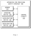
FIG. 1 , an apparatus 100 for providing a safety strategy in a vehicle in some forms of the present disclosure may include asensor 110, asteering device 120, anacceleration device 130, adeceleration device 140, and acontrol circuit 150. The apparatus 100 for providing the safety strategy inFIG. 1 may be a portion of an autonomous system and may be loaded into the vehicle. - The
sensor 110 may be configured to sense information about the outside and inside of the vehicle. For example, thesensor 110 may be configured to sense information about an external object. Thesensor 110 may include a radar, a light detection and ranging (LiDAR), a camera, and the like, for sensing an environment outside the vehicle. For another example, thesensor 110 may include a wheel speed sensor, a yaw rate sensor, an acceleration sensor, a torque sensor, and the like, for sensing a state of the vehicle. - The
steering device 120 may be configured to control a steering angle of the vehicle. Thesteering device 120 may include, for example, a steering wheel, an actuator interlocked with the steering wheel, and a controller for controlling the actuator and may be controlled by a driver of the vehicle and/or the autonomous system. - The
acceleration device 130 may be configured to control acceleration of the vehicle. Theacceleration device 130 may include, for example, a throttle, an actuator interlocked with the throttle, and a controller for controlling the actuator and may be controlled by the driver and/or the autonomous system. - The
deceleration device 140 may be configured to control deceleration of the vehicle. Thedeceleration device 140 may include, for example, a brake, an actuator interlocked with the brake, and a controller for controlling the actuator and may be controlled by the driver and/or the autonomous system. - The
control circuit 150 may be electrically connected with thesensor 110, thesteering device 120, theacceleration device 130, and thedeceleration device 140. Thecontrol circuit 150 may control thesensor 110, thesteering device 120, theacceleration device 130, and thedeceleration device 140, and may perform a variety of data processing and various arithmetic operations. Thecontrol circuit 150 may be, for example, an electronic control unit (ECU), a micro controller unit (MCU), or a sub-controller, which is loaded into the vehicle. - In some forms of the present disclosure, when a predetermined condition is met, the
control circuit 150 may initiate a minimum risk maneuver (MRM). For example, after a transition demand (TD) occurs, when control authority is not handed over or when an emergency critical situation is detected, thecontrol circuit 150 may execute the MRM. Thecontrol circuit 150 may perform stopping control or deceleration control according to a predetermined MRM. - In some forms of the present disclosure, the
control circuit 150 may determine a lateral location of the vehicle based on information obtained by thesensor 110 and a location of a driving lane of the vehicle in a road. Thecontrol circuit 150 may obtain information about an external object using thesensor 110. Thecontrol circuit 150 may obtain information about whether a lane where the vehicle is located is an nth lane in a road on which the vehicle is traveling. When executing an MRM based on the information, thecontrol circuit 150 may determine a target lateral location of the vehicle. For example, thecontrol circuit 150 may determine the target lateral location as a location adjacent to a left or right end of the driving lane or the center of the driving lane. Thecontrol circuit 150 may control the vehicle to move to the determined lateral location while executing the MRM. After moving the vehicle to the determined lateral location, thecontrol circuit 150 may perform stopping control or deceleration control. - In some forms of the present disclosure, while the driving lane is neighboring to one end of the road on which the vehicle is traveling, the
control circuit 150 may control the vehicle to be adjacent to the one end of the road while executing an MRM. When the driving lane is not neighboring to the one end of the road, thecontrol circuit 150 may perform a lane change to a lane neighboring to the one end of the road and may control the vehicle to be adjacent to the one end of the road neighboring to the changed lane. For example, thecontrol circuit 150 may perform a lane change to a lane close to the driving lane between a lane neighboring to the left end of the road or a lane neighboring to the right end of the road. For another example, thecontrol circuit 150 may perform a lane change to a lane capable of being changed within a specified time between the lane neighboring to the left end of the road or the lane neighboring to the right end of the road. For another example, thecontrol circuit 150 may perform a lane change to a lane in a predetermined direction between the lane neighboring to the left end of the road or the lane neighboring to the right end of the road. After performing the lane change, thecontrol circuit 150 may control the vehicle to be adjacent to the one end of the road. - When a shoulder is not included in the road on which the vehicle is traveling, the vehicle may be stopped as close to a road edge as possible by calculating a distance from an outermost lane to the road edge, without stopping at the lane center. Thus, a remote vehicle may be easy to avoid the stopped vehicle to reduce a risk of collision.
- In some forms of the present disclosure, when the driving lane is not neighboring to one end of the road, the
control circuit 150 may control the vehicle to be located on the center of the driving lane while executing an MRM. For example, when it is impossible to perform a lane change within a specified time (when a risk of collision is high upon a lane change), thecontrol circuit 150 may control the vehicle to be located on the center of the driving lane without performing the lane change. - In some forms of the present disclosure, when a shoulder is included in the road, the
control circuit 150 may control the vehicle to move to the shoulder while executing an MRM. For example, when it is possible to perform a lane change to the shoulder within a specified time (when there is no risk of collision upon a lane change), thecontrol circuit 150 may control the vehicle to move to the shoulder. After the vehicle moves to the shoulder, thecontrol circuit 150 may perform stopping control or deceleration control. -
FIG. 2 is a block diagram illustrating a configuration of an apparatus for providing a safety strategy in a vehicle in some forms of the present disclosure. - Referring to
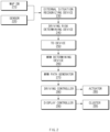
FIG. 2 , the apparatus for providing the safety strategy in some forms of the present disclosure may include an externalsituation recognizing device 230, a drivingrisk determining device 240, a transition demand (TD)device 250, anMRM determining device 260, anMRM path generator 270, a drivingcontroller 280, and adisplay controller 290. The apparatus for providing the safety strategy may determine a driving risk situation and may provide an MRM suitable for the situation. - The external
situation recognizing device 230 may obtain information (e.g., a location, a speed, acceleration, an expected trajectory, and the like) about a static object, such as a structure, a guiderail, and a stopped object, and a moving object, such as an external vehicle, using asensor 220. The externalsituation recognizing device 230 may obtain information about a road on which the vehicle is currently traveling (e.g., a type of the road, whether there is a shoulder, and the like), based on a map database (DB) 210. - The driving
risk determining device 240 may expect a probability of collision with the static object or the moving object and a departure from an operational design domain (ODD) of autonomous control. The drivingrisk determining device 240 may recognize an event (e.g., a collision with the static object, a collision with the moving object, a departure from the ODD, or the like) based on the expectation and may predict a time when the event occurs, a location where the event occurs, and the like. - The
TD device 250 may provide a TD to a driver of the vehicle. The TD may be changed according to a type of the event and over a time remaining until the event occurs. For example, a type of the TD (e.g., a visual notification, an audible notification, an emergency call, and the like) may be changed, and strength of the TD may be adjusted. - The
MRM determining device 260 may determine an MRM suitable for a current situation. The MRM may include constant-speed driving after deceleration, stopping in a driving lane, stopping after a lane change, and the like. TheMRM determining device 260 may select an MRM suitable for the current situation among various types of MRMs. When the constant-speed driving is selected, theMRM determining device 260 may calculate a final speed. For example, theMRM determining device 260 may determine whether the detected event is an event capable of performing low-speed driving (e.g., a departure from an ODD, or the like). When the detected event is the event capable of performing the low-speed driving, theMRM determining device 260 may select a strategy for constant-speed driving after deceleration. When there is a shoulder in a road on which the vehicle is traveling, theMRM determining device 260 may determine whether it is possible to perform a lane change to the shoulder. When it is possible to perform the lane change to the shoulder, theMRM determining device 260 may select a strategy for stopping in the shoulder. When there is no shoulder in the road, theMRM determining device 260 may select a strategy for stopping in a lane. When there is no shoulder in the road, theMRM determining device 260 may select the strategy for stopping in the lane and may control the vehicle to stop on a location adjacent to an edge of the road. - The
MRM path generator 270 may generate a driving path according to the determined MRM. TheMRM path generator 270 may output a location where the vehicle is traveling, a heading angle of the vehicle, and a speed of the vehicle. For example, when the strategy for stopping in the shoulder is selected, theMRM path generator 270 may determine whether it is possible to perform a lane change to the shoulder before an event occurs. When it is possible to perform the lane change to the shoulder, theMRM path generator 270 may generate a driving path for stopping after performing the lane change to the shoulder. When it is impossible to perform the lane change to the shoulder, theMRM path generator 270 may perform stopping control in a driving lane. For another example, when the strategy for stopping in the lane is selected, theMRM path generator 270 may calculate a target lateral location adjacent to a road edge when a current lane is a first lane or a final lane and may generate a driving path for stopping in the target lateral location. When the current lane does not correspond to the first lane or the final lane, theMRM path generator 270 may generate a driving path for stopping on the center of a driving lane. - The driving
controller 280 may control a behavior of the vehicle by operating an actuator285. The drivingcontroller 280 may control the vehicle depending on the generated path. - The
display controller 290 may provide visual information to the driver through acluster 295. -
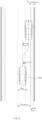
FIG. 3 is a drawing illustrating an exemplary operation of an apparatus for providing a safety strategy in a vehicle in some forms of the present disclosure. - Referring to
FIG. 3 , avehicle 310 in some forms of the present disclosure may be traveling on a lane adjacent to a right end of a road. Thevehicle 310 may perform autonomous control using an autonomous system. While performing the autonomous control, thevehicle 310 may detect an event for requiring to hand over control authority. Thevehicle 310 may request its driver to hand over control authority. When the driver does not take over the control authority, thevehicle 310 may initiate an MRM. When thevehicle 310 is traveling on the lane adjacent to the right end of the road, it may execute a strategy for stopping on a location adjacent to the right end of the road. For example, thevehicle 310 may stop on a location away from the right end of the road at a specified distance TBD. Thus, although thevehicle 310 stops, a following vehicle may easily avoid the stoppedvehicle 310. -
FIG. 4 is a drawing illustrating an exemplary operation of an apparatus for providing a safety strategy in a vehicle in some forms of the present disclosure. - Referring to
FIG. 4 , avehicle 410 in some forms of the present disclosure may calculate a target lateral location dTarget in consideration of a current lateral location dLatOffset of thevehicle 410 from the center of a driving lane, a width dLaneWidth of the driving lane, a distance dLine2RoadEdege between a line and a road edge, a width WEgo of thevehicle 410, a safety distance dmargin, and the like. An exemplary equation for calculating the target lateral location dTarget is Equation 1 below.
- The
vehicle 410 may calculate a path for moving from the current lateral location dLatOffset to the target lateral location dTarget in a lateral direction. The path may be calculated as, for example, a cubic plane curve which connects the current lateral location dLatOffset with the target lateral location dTarget. Thevehicle 410 may control itself along the calculated path. -
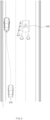
FIG. 5 is a drawing illustrating an exemplary operation of an apparatus for providing a safety strategy in a vehicle in some forms of the present disclosure. - Referring to
FIG. 5 , avehicle 510 in some forms of the present disclosure may be traveling on a lane adjacent to a left end of a road. Thevehicle 510 may perform autonomous control using an autonomous system. While performing the autonomous control, thevehicle 510 may detect an event for requiring to hand over control authority. Thevehicle 510 may request its driver to hand over control authority. When the driver does not take over the control authority, thevehicle 510 may initiate an MRM. When thevehicle 510 is traveling on the lane adjacent to the left end of the road, it may execute a strategy for stopping on a location adjacent to the left end of the road. For example, thevehicle 510 may stop on a location away from the left end of the road at a specified distance. Meanwhile, thevehicle 510 may detect anexternal object 520. It may be difficult to perform a lane change to a right lane due to theexternal object 520. Thus, thevehicle 510 may execute a strategy for stopping on the location adjacent to the left end of the road without moving to a right end of the road. -
FIG. 6 is a drawing illustrating an exemplary operation of an apparatus for providing a safety strategy in a vehicle in some forms of the present disclosure. - Referring to
FIG. 6 , avehicle 610 in some forms of the present disclosure may be traveling on the center of a lane of a road. Thevehicle 610 may perform autonomous control using its autonomous system. While performing the autonomous control, thevehicle 610 may detect an event for requiring to hand over control authority. Thevehicle 610 may request its driver to hand over control authority. When the driver does not take over the control authority, thevehicle 610 may initiate an MRM. When thevehicle 610 is traveling on the center of the lane of the road, it may execute a strategy for stopping or decelerating in a driving lane. Meanwhile, thevehicle 610 may detect anexternal object 620. It may be difficult to perform a lane change to a right lane due to theexternal object 620 although there is a shoulder in the lane. Thus, thevehicle 610 may execute a strategy for stopping in the driving lane without moving to the right lane. -
FIG. 7 is a drawing illustrating an exemplary operation of an apparatus for providing a safety strategy in a vehicle in some forms of the present disclosure. - Referring to
FIG. 7 , avehicle 710 in some forms of the present disclosure may be traveling on a lane adjacent to a right end of a road. Thevehicle 710 may initiate an MRM. When a road on which thevehicle 710 is traveling includes a shoulder, thevehicle 710 may execute a strategy for stopping in the shoulder included in the road. For example, thevehicle 710 may execute a strategy for performing a lane change to the shoulder and stopping in the shoulder. -
FIG. 8 is a flowchart illustrating a method for providing a safety strategy in a vehicle in some forms of the present disclosure. - Hereinafter, it is assumed that a vehicle including an apparatus 100 for providing a safety strategy in
FIG. 1 performs a process ofFIG. 8 . Furthermore, in a description ofFIG. 8 , an operation described as being performed by the vehicle may be understood as being controlled by acontrol circuit 150 of the apparatus 100 for providing the safety strategy. - Referring to
FIG. 8 , inoperation 810, the vehicle may initiate an MRM. For example, while the vehicle performs autonomous control, when an event for control authority transition occurs and when a driver of the vehicle does not take over control authority, the vehicle may execute the MRM. - In
operation 820, the vehicle may determine its lateral location based on sensor information and a location of a driving lane of the vehicle in a road. For example, the vehicle may determine a target lateral location of the MRM in consideration of information about an external object, information about the road, and information about its current location. The target lateral location may be, for example, the center of a driving lane, a shoulder, or a location adjacent to a road edge. - In
operation 830, while executing the MRM, the vehicle may control itself to move to the determined lateral location. For example, the vehicle may move to the location adjacent to the road edge and may perform stopping or deceleration control. For another example, the vehicle may perform stopping or deceleration control on the center of the lane. For another example, the vehicle may move to the shoulder and may perform stopping or deceleration control. -
FIG. 9 is a block diagram illustrating a configuration of a computing system in some forms of the present disclosure. - Referring to
FIG. 9 , acomputing system 1000 may include at least oneprocessor 1100, amemory 1300, a userinterface input device 1400, a userinterface output device 1500, astorage 1600, and anetwork interface 1700, which are connected with each other via abus 1200. - The
processor 1100 may be a central processing unit (CPU) or a semiconductor device for performing processing of instructions stored in thememory 1300 and/or thestorage 1600. Each of thememory 1300 and thestorage 1600 may include various types of volatile or non-volatile storage media. For example, thememory 1300 may include a read only memory (ROM) and a random access memory (RAM). - Thus, the operations of the methods or algorithms described in some forms of the present disclosure disclosed in the specification may be directly implemented with a hardware module, a software module, or combinations thereof, executed by the
processor 1100. The software module may reside on a storage medium (i.e., thememory 1300 and/or the storage 1600) such as a RAM, a flash memory, a ROM, an erasable and programmable ROM (EPROM), an electrically EPROM (EEPROM), a register, a hard disc, a removable disc, or a compact disc-ROM (CD-ROM). An exemplary storage medium may be coupled to theprocessor 1100. Theprocessor 1100 may read out information from the storage medium and may write information in the storage medium. Alternatively, the storage medium may be integrated with theprocessor 1100. The processor and storage medium may reside in an application specific integrated circuit (ASIC). The ASIC may reside in a user terminal. Alternatively, the processor and storage medium may reside as a separate component of the user terminal. - The apparatus for providing the safety strategy in the vehicle in some forms of the present invention may enhance the safety of the vehicle in a relationship between the vehicle and a surrounding vehicle upon stopping or deceleration control by determining a target lateral location of the vehicle when executing an MRM based on sensor information and location information of the vehicle.
- In addition, various effects directly or indirectly ascertained through the present invention may be provided.
Claims (15)
- An apparatus for providing a safety strategy (100) in a vehicle, the apparatus (100) comprising:a sensor (110) configured to sense information about an external object; anda control circuit (150) electrically connected with the sensor (110) and configured to:initiate a minimum risk strategy, MRM, when control authority is not handed over after transition demand occurs;determine a lateral location of the vehicle based on the sensed information and a location of a driving lane of the vehicle on a road; andmove the vehicle to the determined lateral location during an execution of the MRM,characterized in thatthe control circuit determines the lateral location in consideration of a distance from an outermost lane of the road to an edge of the road.
- The apparatus (100) of claim 1, wherein the control circuit (150) is configured to:
stop or decelerate the vehicle based on the MRM. - The apparatus (100) of claim 1 or 2, wherein the control circuit (150) is configured to:
move the vehicle adjacent to one end of the road during the execution of the MRM when the driving lane is adjoining to the one end of the road. - The apparatus (100) of claim 1, 2 or 3, wherein the control circuit (150) is configured to:perform a lane change to a lane adjoining to the one end of the road when the driving lane is not adjoining to the one end of the road; andmove the vehicle adjacent to the one end of the road that is adjoining to the changed lane during the execution of the MRM.
- The apparatus (100) of claim 4, wherein the control circuit (150) is configured to:
perform the lane change to either a lane adjoining to a left end of the road or a lane adjoining to a right end of the road such that the changed lane is close to the driving lane. - The apparatus (100) of claim 4, wherein the control circuit (150) is configured to:
perform the lane change to either the lane adjoining to the left end of the road or the lane adjoining to the right end of the road within a predetermined amount of time. - The apparatus (100) of one of claims 1 to 6, wherein the control circuit (150) is configured to:
move the vehicle to a center of the driving lane during the execution of the MRM when the driving lane is not adjoining to the one end of the road. - The apparatus (100) of claim 7, wherein the control circuit (150) is configured to:
move the vehicle to the center of the driving lane when performing the lane change within the predetermined amount of time is not possible. - The apparatus (100) of one of claims 1 to 8, wherein the control circuit (150) is configured to:
move the vehicle to a shoulder during the execution of the MRM when the shoulder is included in the road. - The apparatus (100) of claim 9, wherein the control circuit (150) is configured to:
move the vehicle to the shoulder when performing the lane change to the shoulder within the predetermined amount of time is possible. - A method for providing a safety strategy in a vehicle, the method comprising:when control authority is not handed over after a transition demand occurs, initiating, with a control circuit (150), a minimum risk strategy, MRM;determining, with the control circuit (150), a lateral location of the vehicle based on sense information about an external object and a location of a driving lane of the vehicle on a road; andmoving, with the control circuit (150), the vehicle to the determined lateral location during an execution of the MRM,characterized in that the determining the lateral location of the vehicle comprises determining, with the control circuit, the lateral location in consideration of a distance from an outermost lane of the road to an edge of the road.
- The method of claim 11, wherein moving the vehicle comprises:
stopping or deceleration, with the control circuit (150), the vehicle based on the MRM. - The method of claim 11 or 12, wherein moving the vehicle comprises:
moving, with the control circuit (150), the vehicle adjacent to one end of the road during the execution of the MRM when the driving lane is adjoining to the one end of the road. - The method of claim 11 or 12, wherein moving the vehicle comprises:when the driving lane is not adjoining to the one end of the road, performing, with the control circuit (150), a lane change to a lane adjoining to the one end of the road; andmoving, with the control circuit (150), the vehicle adjacent to the one end of the road that is adjoining to the changed lane during the execution of the MRM.
- The method of claim 11 or 12, wherein moving the vehicle comprises:
when the driving lane is not adjoining to the one end of the road, moving, with the control circuit (150), the vehicle to a center of the driving lane during the execution of the MRM.
Applications Claiming Priority (2)
| Application Number | Priority Date | Filing Date | Title |
|---|---|---|---|
| US201862655831P | 2018-04-11 | 2018-04-11 | |
| KR1020190013932A KR20190124130A (en) | 2018-04-11 | 2019-02-01 | Apparatus and method for providing safety strategy of vehicle |
Publications (3)
| Publication Number | Publication Date |
|---|---|
| EP3552901A2 EP3552901A2 (en) | 2019-10-16 |
| EP3552901A3 EP3552901A3 (en) | 2020-04-29 |
| EP3552901B1 true EP3552901B1 (en) | 2025-07-02 |
Family
ID=66092153
Family Applications (1)
| Application Number | Title | Priority Date | Filing Date |
|---|---|---|---|
| EP19167264.1A Active EP3552901B1 (en) | 2018-04-11 | 2019-04-04 | Apparatus and method for providing safety strategy in vehicle |
Country Status (4)
| Country | Link |
|---|---|
| US (1) | US11173912B2 (en) |
| EP (1) | EP3552901B1 (en) |
| KR (1) | KR20250026810A (en) |
| CN (1) | CN110371101A (en) |
Families Citing this family (12)
| Publication number | Priority date | Publication date | Assignee | Title |
|---|---|---|---|---|
| KR102075329B1 (en) * | 2017-04-14 | 2020-02-07 | 닛산 지도우샤 가부시키가이샤 | Vehicle control method and vehicle control device |
| JP6600889B2 (en) * | 2017-12-13 | 2019-11-06 | 本田技研工業株式会社 | Vehicle control device, vehicle control method, and program |
| JP7165093B2 (en) * | 2019-03-29 | 2022-11-02 | 本田技研工業株式会社 | vehicle control system |
| WO2020249235A1 (en) * | 2019-06-14 | 2020-12-17 | Volvo Truck Corporation | A method for quantifying correctness of a vehicle model |
| DE102019213185B4 (en) * | 2019-09-02 | 2025-07-10 | Volkswagen Aktiengesellschaft | Lateral guidance of a vehicle using environmental data collected from other vehicles |
| KR20210119617A (en) * | 2020-03-24 | 2021-10-06 | 현대자동차주식회사 | Apparatus for controlling autonomous driving of a vehicle, system having the same and method thereof |
| JP7507587B2 (en) * | 2020-03-30 | 2024-06-28 | 本田技研工業株式会社 | Vehicle control device, vehicle control method, and program |
| KR20220017048A (en) * | 2020-08-03 | 2022-02-11 | 현대자동차주식회사 | System and method for autonomous driving control |
| JP7355057B2 (en) * | 2021-03-24 | 2023-10-03 | 株式会社デンソー | Vehicle control device and vehicle control method |
| DE102021003284A1 (en) * | 2021-06-25 | 2022-12-29 | Mercedes-Benz Group AG | Method of operating a vehicle |
| EP4194304B1 (en) * | 2021-12-08 | 2025-07-30 | Zenseact AB | Precautionary planning of minimal risk maneuvers |
| JP7751793B2 (en) * | 2022-05-02 | 2025-10-09 | マツダ株式会社 | Vehicle control system and vehicle control method |
Citations (4)
| Publication number | Priority date | Publication date | Assignee | Title |
|---|---|---|---|---|
| EP2314490A1 (en) * | 2009-10-22 | 2011-04-27 | Audi AG | Method for controlling the operation of a fully automatic driver assistance system of a motor vehicle for independent vehicle guidance and motor vehicle |
| US20150094899A1 (en) * | 2013-10-01 | 2015-04-02 | Volkswagen Ag | Method for Driver Assistance System of a Vehicle |
| EP3075618A2 (en) * | 2015-04-01 | 2016-10-05 | Toyota Jidosha Kabushiki Kaisha | Vehicle control apparatus |
| US20180088574A1 (en) * | 2016-09-29 | 2018-03-29 | Magna Electronics Inc. | Handover procedure for driver of autonomous vehicle |
Family Cites Families (218)
| Publication number | Priority date | Publication date | Assignee | Title |
|---|---|---|---|---|
| US4361202A (en) | 1979-06-15 | 1982-11-30 | Michael Minovitch | Automated road transportation system |
| DE4313568C1 (en) | 1993-04-26 | 1994-06-16 | Daimler Benz Ag | Method for guiding a lane change by a motor vehicle |
| DE19632929C1 (en) | 1996-08-16 | 1997-11-27 | Daimler Benz Ag | Automatic motor vehicle transverse guidance device |
| DE19821122A1 (en) | 1997-12-15 | 1999-06-17 | Volkswagen Ag | Procedure for controlling speed and distance in overtaking maneuvers |
| JP2000198458A (en) | 1999-01-08 | 2000-07-18 | Mazda Motor Corp | Vehicle control device |
| JP3529037B2 (en) | 1999-08-02 | 2004-05-24 | 日産自動車株式会社 | Lane tracking device |
| DE10114187A1 (en) | 2001-03-23 | 2002-09-26 | Bosch Gmbh Robert | Method and device for supporting an overtaking process in motor vehicles |
| JP2003025868A (en) | 2001-07-16 | 2003-01-29 | Nissan Motor Co Ltd | Vehicle lane change support device |
| DE10218010A1 (en) | 2002-04-23 | 2003-11-06 | Bosch Gmbh Robert | Method and device for lateral guidance support in motor vehicles |
| DE602004008541T2 (en) | 2003-07-07 | 2008-04-30 | Nissan Motor Co., Ltd., Yokohama | Control system for a vehicle for keeping the lane |
| US7821421B2 (en) | 2003-07-07 | 2010-10-26 | Sensomatix Ltd. | Traffic information system |
| DE10350779A1 (en) | 2003-10-30 | 2005-06-02 | Robert Bosch Gmbh | Lane keeping system for a motor vehicle and operating method |
| JP4032253B2 (en) | 2003-12-17 | 2008-01-16 | ソニー株式会社 | Optical communication apparatus and vehicle control method |
| DE102004005815B3 (en) | 2004-02-06 | 2005-06-09 | Audi Ag | Automobile with selectively operated driver support systems and device for combined display of status of driver support systems via combined optical symbol |
| KR100578573B1 (en) | 2004-05-06 | 2006-05-12 | 기아자동차주식회사 | Speed limit indication and warning device |
| JP4379199B2 (en) | 2004-05-17 | 2009-12-09 | 日産自動車株式会社 | Lane change support apparatus and method |
| DE102004029369B4 (en) | 2004-06-17 | 2016-09-15 | Robert Bosch Gmbh | Lane change assistant for motor vehicles |
| DE102004048009A1 (en) | 2004-10-01 | 2006-04-06 | Robert Bosch Gmbh | Method and device for driver assistance |
| DE102004048468A1 (en) | 2004-10-05 | 2006-04-13 | Siemens Ag | System and method for setting the speed of a vehicle to a maximum permissible speed |
| US7881848B2 (en) | 2006-04-28 | 2011-02-01 | Nissan Motor Co., Ltd. | Lane departure prevention apparatus and method |
| JP4582052B2 (en) | 2006-06-07 | 2010-11-17 | トヨタ自動車株式会社 | Driving support device |
| JP4449960B2 (en) | 2006-08-22 | 2010-04-14 | トヨタ自動車株式会社 | Steering support device |
| JP4525670B2 (en) | 2006-11-20 | 2010-08-18 | トヨタ自動車株式会社 | Travel control plan generation system |
| DE102007005245A1 (en) | 2007-02-02 | 2007-11-22 | Daimlerchrysler Ag | Method for operating a driver assistance system e.g. for motor vehicle, involves using display instrument to show relevant traffic information at given time point |
| JP4748122B2 (en) | 2007-06-28 | 2011-08-17 | 日産自動車株式会社 | Lane departure prevention device |
| JP4366419B2 (en) | 2007-09-27 | 2009-11-18 | 株式会社日立製作所 | Driving support device |
| US8090516B2 (en) | 2007-11-20 | 2012-01-03 | Nissan Motor Co., Ltd. | Lane deviation prevention device and method |
| DE102008001677A1 (en) | 2008-05-09 | 2009-11-12 | Robert Bosch Gmbh | Assistance system for driver assistance in vehicles |
| US8392064B2 (en) | 2008-05-27 | 2013-03-05 | The Board Of Trustees Of The Leland Stanford Junior University | Systems, methods and devices for adaptive steering control of automotive vehicles |
| US8170739B2 (en) | 2008-06-20 | 2012-05-01 | GM Global Technology Operations LLC | Path generation algorithm for automated lane centering and lane changing control system |
| US9846049B2 (en) | 2008-07-09 | 2017-12-19 | Microsoft Technology Licensing, Llc | Route prediction |
| JP2010125923A (en) * | 2008-11-26 | 2010-06-10 | Toyota Motor Corp | Emergency refuge device |
| WO2010088869A1 (en) | 2009-02-03 | 2010-08-12 | Adc Automotive Distance Control Systems Gmbh | Speed pre-setting for a vehicle having automatic longitudinal control |
| EP2423901B1 (en) | 2009-04-23 | 2017-03-15 | Panasonic Intellectual Property Management Co., Ltd. | Driving support device, driving support method and program |
| US8164543B2 (en) | 2009-05-18 | 2012-04-24 | GM Global Technology Operations LLC | Night vision on full windshield head-up display |
| DE102010004625A1 (en) | 2010-01-14 | 2011-07-21 | Ford Global Technologies, LLC, Mich. | Method and device for assisting a driver in an overtaking process |
| US8384534B2 (en) | 2010-01-14 | 2013-02-26 | Toyota Motor Engineering & Manufacturing North America, Inc. | Combining driver and environment sensing for vehicular safety systems |
| JP5324658B2 (en) | 2010-03-12 | 2013-10-23 | トヨタ自動車株式会社 | Steering support device |
| US8618922B2 (en) * | 2010-03-30 | 2013-12-31 | GM Global Technology Operations LLC | Method and system for ensuring operation of limited-ability autonomous driving vehicles |
| US8977419B2 (en) | 2010-12-23 | 2015-03-10 | GM Global Technology Operations LLC | Driving-based lane offset control for lane centering |
| WO2012131405A1 (en) | 2011-03-29 | 2012-10-04 | Josic Ante | Automatic control of maximum speed and automatic control system thereof |
| DE102011016770B4 (en) | 2011-04-12 | 2021-02-04 | Daimler Ag | Method for assisting a driver of a vehicle when changing lanes and device for carrying out the method |
| DE102011016771A1 (en) | 2011-04-12 | 2012-10-18 | Daimler Ag | Device for operating lane change assist in vehicle, has manual operating unit for driver-side activation of lane change, which is coupled to or integrated with direction sensor |
| JP2012226392A (en) | 2011-04-14 | 2012-11-15 | Honda Elesys Co Ltd | Drive support system |
| JP5763757B2 (en) | 2011-05-20 | 2015-08-12 | 本田技研工業株式会社 | Lane change support system |
| DE112011105432B4 (en) * | 2011-07-11 | 2018-07-12 | Toyota Jidosha Kabushiki Kaisha | Vehicle emergency evacuation device |
| DE102011109618A1 (en) | 2011-08-05 | 2013-02-07 | Daimler Ag | Method for operating vehicle, involves automatically determining driving impairment of driver while activating engagement to brake, steering or drive train function of vehicle, so that vehicle is decelerated to standstill |
| DE102011081892A1 (en) | 2011-08-31 | 2013-02-28 | Robert Bosch Gmbh | Method for lane monitoring and lane monitoring system for a vehicle |
| US8838325B2 (en) | 2011-09-12 | 2014-09-16 | Ford Global Technologies | Vehicle shut-down functionality for peps-equipped vehicles |
| DE102011086241B4 (en) * | 2011-11-14 | 2018-04-05 | Robert Bosch Gmbh | Method for the safe parking of a vehicle |
| DE102012001405A1 (en) | 2012-01-26 | 2012-11-22 | Daimler Ag | Method for performing lane change of vehicle from current lane, involves determining whether lane change of vehicle is safely feasible along determined transition trajectory, based on movement of other road users |
| DE102012002304A1 (en) | 2012-02-06 | 2013-08-08 | Audi Ag | Apparatus for automated driving of a motor vehicle and method for operating a motor vehicle |
| JP5868218B2 (en) | 2012-02-28 | 2016-02-24 | 株式会社日本自動車部品総合研究所 | Vehicle control device |
| US8457827B1 (en) | 2012-03-15 | 2013-06-04 | Google Inc. | Modifying behavior of autonomous vehicle based on predicted behavior of other vehicles |
| US9315178B1 (en) | 2012-04-13 | 2016-04-19 | Google Inc. | Model checking for autonomous vehicles |
| DE102012008090A1 (en) | 2012-04-21 | 2013-10-24 | Volkswagen Aktiengesellschaft | Method and device for emergency stop of a motor vehicle |
| US8521352B1 (en) | 2012-05-07 | 2013-08-27 | Google Inc. | Controlling a vehicle having inadequate map data |
| DE102012014717A1 (en) * | 2012-07-25 | 2014-01-30 | Audi Ag | Method and driver assistance system for operating a vehicle in the event of a driver's health disorder |
| US8798841B1 (en) | 2013-03-14 | 2014-08-05 | GM Global Technology Operations LLC | System and method for improving sensor visibility of vehicle in autonomous driving mode |
| US9751534B2 (en) | 2013-03-15 | 2017-09-05 | Honda Motor Co., Ltd. | System and method for responding to driver state |
| GB2512317A (en) | 2013-03-26 | 2014-10-01 | Jaguar Land Rover Ltd | Vehicle control system and method |
| US8874301B1 (en) | 2013-07-09 | 2014-10-28 | Ford Global Technologies, Llc | Autonomous vehicle with driver presence and physiological monitoring |
| US8930060B1 (en) * | 2013-07-15 | 2015-01-06 | Ford Global Technologies | Post-impact path assist for vehicles |
| BR112016007927B1 (en) | 2013-10-11 | 2021-01-19 | Nissan Motor Co., Ltd. | displacement control device and displacement control method |
| KR20150061752A (en) | 2013-11-28 | 2015-06-05 | 현대모비스 주식회사 | Device for driving assist and method for activating the function automatically by the device |
| US9988047B2 (en) | 2013-12-12 | 2018-06-05 | Magna Electronics Inc. | Vehicle control system with traffic driving control |
| JP6237256B2 (en) | 2014-01-21 | 2017-11-29 | 日産自動車株式会社 | Vehicle speed control device |
| KR20150087619A (en) | 2014-01-22 | 2015-07-30 | 한국전자통신연구원 | Apparatus and method for guiding lane change based on augmented reality |
| KR101551096B1 (en) | 2014-06-05 | 2015-09-21 | 현대자동차주식회사 | Lane changing apparatus and method of autonomous vehicle |
| US9457807B2 (en) | 2014-06-05 | 2016-10-04 | GM Global Technology Operations LLC | Unified motion planning algorithm for autonomous driving vehicle in obstacle avoidance maneuver |
| JP2016000602A (en) | 2014-06-12 | 2016-01-07 | トヨタ自動車株式会社 | Lane change support device |
| JP6031066B2 (en) | 2014-06-17 | 2016-11-24 | 富士重工業株式会社 | Vehicle travel control device |
| WO2016024315A1 (en) | 2014-08-11 | 2016-02-18 | 日産自動車株式会社 | Travel control device and method for vehicle |
| EP3001272B1 (en) | 2014-09-26 | 2017-04-12 | Volvo Car Corporation | Method of trajectory planning for yielding manoeuvres |
| US9499197B2 (en) | 2014-10-15 | 2016-11-22 | Hua-Chuang Automobile Information Technical Center Co., Ltd. | System and method for vehicle steering control |
| JP6086106B2 (en) | 2014-10-16 | 2017-03-01 | トヨタ自動車株式会社 | Driving assistance device |
| DE102014225680A1 (en) | 2014-12-12 | 2016-06-16 | Volkswagen Aktiengesellschaft | Method and device for the takeover request of a driving task to the driver of a vehicle as part of the automatic driving of the vehicle |
| JP6470039B2 (en) | 2014-12-26 | 2019-02-13 | 日立オートモティブシステムズ株式会社 | Vehicle control system |
| US10705521B2 (en) | 2014-12-30 | 2020-07-07 | Visteon Global Technologies, Inc. | Autonomous driving interface |
| JP6137212B2 (en) | 2015-02-02 | 2017-05-31 | トヨタ自動車株式会社 | Driving assistance device |
| JP6528690B2 (en) * | 2015-02-10 | 2019-06-12 | 株式会社デンソー | Save control device, save control method |
| JP2016151815A (en) | 2015-02-16 | 2016-08-22 | 株式会社デンソー | Driving support device |
| JP6154411B2 (en) | 2015-02-27 | 2017-06-28 | 本田技研工業株式会社 | Vehicle warning device |
| JP2016168985A (en) | 2015-03-16 | 2016-09-23 | トヨタ自動車株式会社 | Travel control device |
| DE102015205131A1 (en) | 2015-03-20 | 2016-09-22 | Bayerische Motoren Werke Aktiengesellschaft | Method for operating an at least partially automated moving vehicle within a route |
| JP2016196285A (en) | 2015-04-03 | 2016-11-24 | 株式会社デンソー | Travel controlling device and travel controlling method |
| CN107408349B (en) * | 2015-04-03 | 2022-06-03 | 株式会社电装 | Information presentation device and information presentation method |
| JP6292218B2 (en) * | 2015-04-03 | 2018-03-14 | 株式会社デンソー | Information presenting apparatus and information presenting method |
| DE102015206144B4 (en) * | 2015-04-07 | 2022-10-06 | Volkswagen Aktiengesellschaft | Method and device for safely parking a vehicle |
| DE102015206969B4 (en) | 2015-04-17 | 2022-02-17 | Bayerische Motoren Werke Aktiengesellschaft | Driver assistance system in a motor vehicle |
| WO2016169585A1 (en) | 2015-04-20 | 2016-10-27 | Bayerische Motoren Werke Aktiengesellschaft | Apparatus and method for controlling a user situation awareness modification of a user of a vehicle, and a user situation awareness modification processing system |
| EP3272610B1 (en) | 2015-04-21 | 2019-07-17 | Panasonic Intellectual Property Management Co., Ltd. | Information processing system, information processing method, and program |
| JP6558732B2 (en) | 2015-04-21 | 2019-08-14 | パナソニックIpマネジメント株式会社 | Driving support method, driving support device, driving control device, vehicle, and driving support program using the same |
| JP6252548B2 (en) | 2015-05-22 | 2017-12-27 | トヨタ自動車株式会社 | Vehicle speed limiting device and vehicle speed control device |
| DE102015209476A1 (en) | 2015-05-22 | 2016-11-24 | Robert Bosch Gmbh | System limits of an automatic control |
| KR101750876B1 (en) | 2015-05-28 | 2017-06-26 | 엘지전자 주식회사 | Display apparatus for vehicle and Vehicle |
| JP6156595B2 (en) | 2015-06-11 | 2017-07-05 | 日本精工株式会社 | Electric power steering device |
| US9604641B2 (en) | 2015-06-16 | 2017-03-28 | Honda Motor Co., Ltd. | System and method for providing vehicle collision avoidance at an intersection |
| JP6323402B2 (en) | 2015-07-01 | 2018-05-16 | 株式会社デンソー | In-lane travel control device, in-lane travel control method |
| JP6332170B2 (en) | 2015-07-01 | 2018-05-30 | トヨタ自動車株式会社 | Automatic operation control device |
| MY193056A (en) | 2015-07-28 | 2022-09-26 | Nissan Motor | Method for controlling travel control device, and travel control device |
| MX365237B (en) | 2015-07-28 | 2019-05-27 | Nissan Motor | METHOD OF CONTROLLING THE TRAVEL CONTROL DEVICE AND TRAVEL CONTROL DEVICE. |
| JP6451851B2 (en) | 2015-07-28 | 2019-01-16 | 日産自動車株式会社 | Method for controlling travel control device and travel control device |
| JP6552316B2 (en) | 2015-07-29 | 2019-07-31 | 修一 田山 | Automatic vehicle driving system |
| JP5910904B1 (en) | 2015-07-31 | 2016-04-27 | パナソニックIpマネジメント株式会社 | Driving support device, driving support system, driving support method, driving support program, and autonomous driving vehicle |
| JP5957745B1 (en) | 2015-07-31 | 2016-07-27 | パナソニックIpマネジメント株式会社 | Driving support device, driving support system, driving support method, driving support program, and autonomous driving vehicle |
| JP2017047765A (en) | 2015-09-01 | 2017-03-09 | 本田技研工業株式会社 | Travel control device |
| JP6568759B2 (en) | 2015-09-30 | 2019-08-28 | 日立オートモティブシステムズ株式会社 | Lane change system |
| DE102015219231A1 (en) | 2015-10-06 | 2017-04-06 | Robert Bosch Gmbh | Drive device and method for operating a driver assistance system |
| WO2017060978A1 (en) | 2015-10-06 | 2017-04-13 | 株式会社日立製作所 | Automatic drive control device and automatic drive control method |
| JP6519435B2 (en) | 2015-10-16 | 2019-05-29 | 株式会社デンソー | Notification management apparatus and notification management method |
| DE102015220360A1 (en) * | 2015-10-20 | 2017-04-20 | Robert Bosch Gmbh | Method for selecting an optimized trajectory |
| US10217363B2 (en) | 2015-10-29 | 2019-02-26 | Faraday&Future Inc. | Methods and systems for electronically assisted lane entrance |
| JP6447468B2 (en) | 2015-11-17 | 2019-01-09 | 株式会社デンソー | Driving assistance device |
| DE102015224244A1 (en) | 2015-12-03 | 2017-06-08 | Bayerische Motoren Werke Aktiengesellschaft | Control system for influencing automatic driving functions of a vehicle by a driver |
| US9699289B1 (en) | 2015-12-09 | 2017-07-04 | Toyota Motor Engineering & Manufacturing North America, Inc. | Dynamic vehicle automation level availability indication system and method |
| DE102016007187A1 (en) | 2015-12-19 | 2017-06-22 | Daimler Ag | Method for deactivating an automated driving function of a vehicle and driver assistance system for carrying out the method |
| JP6515823B2 (en) | 2016-01-14 | 2019-05-22 | 株式会社デンソー | Lane change support device |
| JP6787671B2 (en) | 2016-01-14 | 2020-11-18 | 株式会社デンソー | Merge support device |
| US10324463B1 (en) | 2016-01-22 | 2019-06-18 | State Farm Mutual Automobile Insurance Company | Autonomous vehicle operation adjustment based upon route |
| JP6517161B2 (en) | 2016-02-18 | 2019-05-22 | 本田技研工業株式会社 | Traveling control device |
| JP6246844B2 (en) | 2016-02-18 | 2017-12-13 | 本田技研工業株式会社 | Vehicle control system, vehicle control method, and vehicle control program |
| JP6209232B2 (en) | 2016-02-19 | 2017-10-04 | 本田技研工業株式会社 | Lane change support device |
| JP6838248B2 (en) | 2016-02-22 | 2021-03-03 | 日立Astemo株式会社 | Information processing device |
| DE102016203020A1 (en) * | 2016-02-25 | 2017-08-31 | Bayerische Motoren Werke Aktiengesellschaft | Driver assistance system with emergency stop function that can be activated by the parking brake control element |
| JP6308233B2 (en) | 2016-02-29 | 2018-04-11 | トヨタ自動車株式会社 | Vehicle control apparatus and vehicle control method |
| FR3049560B1 (en) | 2016-04-01 | 2019-08-09 | Valeo Schalter Und Sensoren Gmbh | METHOD AND SYSTEM FOR ASSISTING THE CHANGE OF THE TRACK TRACK FOR A MOTOR VEHICLE |
| JP6485399B2 (en) | 2016-04-15 | 2019-03-20 | 株式会社デンソー | Support device |
| EP3232286B1 (en) * | 2016-04-15 | 2018-12-26 | Volvo Car Corporation | Device and method for safety stoppage of an autonomous road vehicle |
| JP6291680B2 (en) | 2016-04-26 | 2018-03-14 | 本田技研工業株式会社 | Vehicle control system, vehicle control method, and vehicle control program |
| JP6275187B2 (en) | 2016-04-28 | 2018-02-07 | 本田技研工業株式会社 | Vehicle control system, vehicle control method, and vehicle control program |
| JP2017200786A (en) | 2016-05-02 | 2017-11-09 | 本田技研工業株式会社 | Vehicle control system, vehicle control method, and vehicle control program |
| KR101779823B1 (en) | 2016-05-10 | 2017-10-10 | 재단법인대구경북과학기술원 | Method for switching the control mode in autonomous vehicle and apparatus thereof |
| JP6387369B2 (en) | 2016-05-23 | 2018-09-05 | 本田技研工業株式会社 | Travel control device |
| JP6535634B2 (en) | 2016-05-26 | 2019-06-26 | 本田技研工業株式会社 | Route guidance apparatus and route guidance method |
| WO2017208754A1 (en) | 2016-06-02 | 2017-12-07 | ソニー株式会社 | Information processing device and information processing method |
| JP6449195B2 (en) | 2016-06-02 | 2019-01-09 | 本田技研工業株式会社 | Driving assistance device |
| JP6778872B2 (en) | 2016-06-28 | 2020-11-04 | パナソニックIpマネジメント株式会社 | Driving support device and driving support method |
| KR101844885B1 (en) | 2016-07-11 | 2018-05-18 | 엘지전자 주식회사 | Driver Assistance Apparatus and Vehicle Having The Same |
| JP6809020B2 (en) | 2016-07-27 | 2021-01-06 | いすゞ自動車株式会社 | Steering assistance device and steering assist method |
| CN107672584B (en) | 2016-07-29 | 2022-05-03 | 福特环球技术公司 | System and method for overtaking lane control |
| JP6831190B2 (en) | 2016-08-15 | 2021-02-17 | トヨタ自動車株式会社 | Control system and control method for autonomous vehicles |
| DE102016215565A1 (en) | 2016-08-19 | 2018-02-22 | Continental Automotive Gmbh | Driver assistance system for overtaking |
| US20180050659A1 (en) | 2016-08-22 | 2018-02-22 | Faraday&Future Inc. | Electric seatbelt notification systems and methods |
| DE102016216134A1 (en) | 2016-08-29 | 2018-03-01 | Bayerische Motoren Werke Aktiengesellschaft | Shifting the lateral position of an automated lateral guide to inform the driver of a required lane change |
| US20180239352A1 (en) | 2016-08-31 | 2018-08-23 | Faraday&Future Inc. | System and method for operating vehicles at different degrees of automation |
| JP6609229B2 (en) | 2016-09-02 | 2019-11-20 | 株式会社デンソー | Object detection device |
| DE102016117438A1 (en) | 2016-09-16 | 2018-03-22 | Knorr-Bremse Systeme für Nutzfahrzeuge GmbH | Method and apparatus for controlling movement of a vehicle and vehicle motion control system |
| US9927810B1 (en) * | 2016-09-19 | 2018-03-27 | Delphi Technologies, Inc. | Automated-vehicle safe-stop-zone mapping system |
| JP6731619B2 (en) | 2016-10-26 | 2020-07-29 | パナソニックIpマネジメント株式会社 | Information processing system, information processing method, and program |
| US11119188B2 (en) | 2016-10-27 | 2021-09-14 | Hitachi Automotive Systems, Ltd. | Malfunction detecting device |
| US9874871B1 (en) | 2016-11-21 | 2018-01-23 | Baidu Usa Llc | Method to dynamically adjusting steering rates of autonomous vehicles |
| US20190279507A1 (en) | 2016-11-25 | 2019-09-12 | Honda Motor Co., Ltd. | Vehicle display control device, vehicle display control method, and vehicle display control program |
| JP6466899B2 (en) | 2016-12-01 | 2019-02-06 | 株式会社Subaru | Vehicle display device |
| JP6490044B2 (en) | 2016-12-09 | 2019-03-27 | 本田技研工業株式会社 | Vehicle control device |
| JP6642399B2 (en) | 2016-12-07 | 2020-02-05 | トヨタ自動車株式会社 | Vehicle travel control device |
| KR20180070401A (en) | 2016-12-16 | 2018-06-26 | 현대자동차주식회사 | System and Method for determining override of self-driving vehicle |
| JP6895634B2 (en) | 2016-12-16 | 2021-06-30 | パナソニックIpマネジメント株式会社 | Information processing systems, information processing methods, and programs |
| JP6919429B2 (en) | 2016-12-21 | 2021-08-18 | トヨタ自動車株式会社 | Driving support device |
| JP6547970B2 (en) | 2016-12-26 | 2019-07-24 | トヨタ自動車株式会社 | Vehicle lane change support device |
| JP2018103766A (en) | 2016-12-26 | 2018-07-05 | トヨタ自動車株式会社 | Lane change support device for vehicle |
| JP6635023B2 (en) | 2016-12-26 | 2020-01-22 | トヨタ自動車株式会社 | Vehicle lane change support device |
| JP6686871B2 (en) | 2016-12-26 | 2020-04-22 | トヨタ自動車株式会社 | Automatic driving system |
| JP6579334B2 (en) | 2016-12-26 | 2019-09-25 | トヨタ自動車株式会社 | Vehicle lane change support device |
| JP6572880B2 (en) | 2016-12-28 | 2019-09-11 | トヨタ自動車株式会社 | Driving assistance device |
| US10569782B2 (en) | 2016-12-29 | 2020-02-25 | Automotive Research & Testing Center | Interactive autonomous safe driving system and deciding method thereof |
| US10254121B2 (en) | 2017-01-23 | 2019-04-09 | Uber Technologies, Inc. | Dynamic routing for self-driving vehicles |
| US10220857B2 (en) | 2017-02-23 | 2019-03-05 | Uber Technologies, Inc. | Vehicle control system |
| US10328973B2 (en) | 2017-03-06 | 2019-06-25 | Ford Global Technologies, Llc | Assisting drivers with roadway lane changes |
| US20180281856A1 (en) | 2017-03-31 | 2018-10-04 | Ford Global Technologies, Llc | Real time lane change display |
| JP2018176935A (en) | 2017-04-10 | 2018-11-15 | トヨタ自動車株式会社 | Automatic driving device |
| DE102018108572B4 (en) | 2017-04-12 | 2023-05-04 | Toyota Jidosha Kabushiki Kaisha | LANE CHANGE ASSISTANT DEVICE FOR A VEHICLE |
| US10814913B2 (en) | 2017-04-12 | 2020-10-27 | Toyota Jidosha Kabushiki Kaisha | Lane change assist apparatus for vehicle |
| US11142246B2 (en) | 2017-04-12 | 2021-10-12 | Toyota Jidosha Kabushiki Kaisha | Lane change assist apparatus for vehicle |
| US10710588B2 (en) | 2017-05-23 | 2020-07-14 | Toyota Motor Engineering & Manufacturing North America, Inc. | Merging and lane change acceleration prediction energy management |
| JP6755390B2 (en) | 2017-05-26 | 2020-09-16 | 本田技研工業株式会社 | Vehicle control system and vehicle control method |
| JP6795457B2 (en) | 2017-06-02 | 2020-12-02 | 本田技研工業株式会社 | Vehicle control systems, vehicle control methods, and vehicle control programs |
| US11364930B2 (en) | 2017-06-02 | 2022-06-21 | Honda Motor Co., Ltd. | Vehicle control system, vehicle control method and program |
| JP6627821B2 (en) | 2017-06-06 | 2020-01-08 | トヨタ自動車株式会社 | Lane change support device |
| JP6673299B2 (en) | 2017-06-06 | 2020-03-25 | トヨタ自動車株式会社 | Steering support device |
| JP6627822B2 (en) | 2017-06-06 | 2020-01-08 | トヨタ自動車株式会社 | Lane change support device |
| JP6642522B2 (en) | 2017-06-06 | 2020-02-05 | トヨタ自動車株式会社 | Lane change support device |
| JP6760204B2 (en) | 2017-06-06 | 2020-09-23 | トヨタ自動車株式会社 | Steering support device |
| JP2019003234A (en) | 2017-06-09 | 2019-01-10 | トヨタ自動車株式会社 | Driving assistance device |
| JP7074432B2 (en) | 2017-06-26 | 2022-05-24 | 本田技研工業株式会社 | Vehicle control systems, vehicle control methods, and vehicle control programs |
| RU2733025C1 (en) | 2017-07-28 | 2020-09-28 | Ниссан Мотор Ко., Лтд. | Display control method and display control device |
| US10551838B2 (en) | 2017-08-08 | 2020-02-04 | Nio Usa, Inc. | Method and system for multiple sensor correlation diagnostic and sensor fusion/DNN monitor for autonomous driving application |
| JP6634637B2 (en) | 2017-08-14 | 2020-01-22 | 本田技研工業株式会社 | Vehicle control system and vehicle control method |
| JP6545760B2 (en) | 2017-08-14 | 2019-07-17 | 本田技研工業株式会社 | Vehicle control system and vehicle control method |
| JP6638178B2 (en) | 2017-08-29 | 2020-01-29 | 本田技研工業株式会社 | Vehicle control system, vehicle control method, and program |
| JP2019043432A (en) | 2017-09-05 | 2019-03-22 | 本田技研工業株式会社 | Vehicle control system, vehicle control method and program |
| JP2019053503A (en) | 2017-09-14 | 2019-04-04 | 本田技研工業株式会社 | Mobile object information acquisition system, mobile object information acquisition method, program, and mobile object |
| US11453393B2 (en) | 2017-10-09 | 2022-09-27 | Magna Electronics Inc. | Autonomous vehicle with path planning system |
| JP6573222B2 (en) | 2017-10-24 | 2019-09-11 | マツダ株式会社 | Vehicle control device |
| JP6573224B2 (en) | 2017-10-24 | 2019-09-11 | マツダ株式会社 | Vehicle control device |
| JP6573223B2 (en) | 2017-10-24 | 2019-09-11 | マツダ株式会社 | Vehicle control device |
| GB2568060B (en) | 2017-11-02 | 2020-02-12 | Jaguar Land Rover Ltd | Controller for a vehicle |
| US10618519B2 (en) | 2017-11-06 | 2020-04-14 | Uatc Llc | Systems and methods for autonomous vehicle lane change control |
| US11163309B2 (en) | 2017-11-30 | 2021-11-02 | Direct Current Capital LLC | Method for autonomous navigation |
| US10597033B2 (en) | 2017-12-05 | 2020-03-24 | Ford Global Technologies, Llc | Monitoring and adjustment of gaps between vehicles |
| KR102014262B1 (en) | 2017-12-11 | 2019-08-26 | 엘지전자 주식회사 | Display device mounted on vehicle and method for controlling the display device |
| US20190197497A1 (en) | 2017-12-22 | 2019-06-27 | Lyft, Inc. | Responses to detected impairments |
| US10761534B2 (en) | 2018-01-30 | 2020-09-01 | Uatc, Llc | Fused sensor view for self-driving truck |
| US10838421B2 (en) | 2018-02-09 | 2020-11-17 | Denso Corporation | Autonomous drive system |
| JP7032170B2 (en) | 2018-02-23 | 2022-03-08 | 本田技研工業株式会社 | Vehicle control device |
| WO2019169031A1 (en) | 2018-02-27 | 2019-09-06 | Nauto, Inc. | Method for determining driving policy |
| JP6725568B2 (en) | 2018-03-13 | 2020-07-22 | 本田技研工業株式会社 | Vehicle control device, vehicle, vehicle control method, and program |
| KR102127741B1 (en) | 2018-03-20 | 2020-07-01 | 모빌아이 비젼 테크놀로지스 엘티디. | Systems and methods for navigation of vehicles |
| US11378956B2 (en) | 2018-04-03 | 2022-07-05 | Baidu Usa Llc | Perception and planning collaboration framework for autonomous driving |
| US11077854B2 (en) | 2018-04-11 | 2021-08-03 | Hyundai Motor Company | Apparatus for controlling lane change of vehicle, system having the same and method thereof |
| EP3552913B1 (en) | 2018-04-11 | 2021-08-18 | Hyundai Motor Company | Apparatus and method for controlling to enable autonomous system in vehicle |
| US10618523B1 (en) | 2018-04-19 | 2020-04-14 | State Farm Mutual Automobile Insurance Company | Assessing driver ability to operate an autonomous vehicle |
| US10935974B1 (en) | 2018-04-19 | 2021-03-02 | State Farm Mutual Automobile Insurance Company | Manual control re-engagement in an autonomous vehicle |
| US11260849B2 (en) | 2018-05-23 | 2022-03-01 | Baidu Usa Llc | Method for determining lane changing trajectories for autonomous driving vehicles |
| US10860023B2 (en) | 2018-06-25 | 2020-12-08 | Mitsubishi Electric Research Laboratories, Inc. | Systems and methods for safe decision making of autonomous vehicles |
| US20200312155A1 (en) | 2018-07-31 | 2020-10-01 | Honda Motor Co., Ltd. | Systems and methods for swarm action |
| US11181920B2 (en) | 2018-08-28 | 2021-11-23 | Denso Corporation | Travel assistance method and travel assistance apparatus |
| JP6931370B2 (en) | 2019-03-25 | 2021-09-01 | 本田技研工業株式会社 | Vehicle control devices, vehicle control methods, and programs |
-
2019
- 2019-04-04 EP EP19167264.1A patent/EP3552901B1/en active Active
- 2019-04-05 US US16/376,661 patent/US11173912B2/en active Active
- 2019-04-10 CN CN201910283528.7A patent/CN110371101A/en active Pending
-
2025
- 2025-02-19 KR KR1020250021720A patent/KR20250026810A/en active Pending
Patent Citations (4)
| Publication number | Priority date | Publication date | Assignee | Title |
|---|---|---|---|---|
| EP2314490A1 (en) * | 2009-10-22 | 2011-04-27 | Audi AG | Method for controlling the operation of a fully automatic driver assistance system of a motor vehicle for independent vehicle guidance and motor vehicle |
| US20150094899A1 (en) * | 2013-10-01 | 2015-04-02 | Volkswagen Ag | Method for Driver Assistance System of a Vehicle |
| EP3075618A2 (en) * | 2015-04-01 | 2016-10-05 | Toyota Jidosha Kabushiki Kaisha | Vehicle control apparatus |
| US20180088574A1 (en) * | 2016-09-29 | 2018-03-29 | Magna Electronics Inc. | Handover procedure for driver of autonomous vehicle |
Also Published As
| Publication number | Publication date |
|---|---|
| US11173912B2 (en) | 2021-11-16 |
| US20190315366A1 (en) | 2019-10-17 |
| CN110371101A (en) | 2019-10-25 |
| EP3552901A2 (en) | 2019-10-16 |
| KR20250026810A (en) | 2025-02-25 |
| EP3552901A3 (en) | 2020-04-29 |
Similar Documents
| Publication | Publication Date | Title |
|---|---|---|
| EP3552901B1 (en) | Apparatus and method for providing safety strategy in vehicle | |
| EP3552911B1 (en) | Apparatus and method for providing safety strategy in vehicle | |
| EP3591638B1 (en) | Drive assistance method and drive assistance device | |
| US8170739B2 (en) | Path generation algorithm for automated lane centering and lane changing control system | |
| US10940867B2 (en) | Substitution of sensor measurement data | |
| EP2765047B1 (en) | Driving assistance system for vehicle | |
| US9643650B2 (en) | Lane change control device and control method | |
| EP3086990B1 (en) | Method and system for driver assistance for a vehicle | |
| EP3552902B1 (en) | Apparatus and method for providing a driving path to a vehicle | |
| US11377103B2 (en) | Vehicle control device and recording medium | |
| US20180056997A1 (en) | Vehicle control device | |
| CN106043302B (en) | The cruise active control system and its method of vehicle | |
| KR20190124119A (en) | Apparatus and method for providing safety strategy of vehicle | |
| US9569968B2 (en) | Method and device for the automated braking and steering of a vehicle | |
| EP3552903B1 (en) | Apparatus and method for providing a safety strategy to a vehicle | |
| EP3552909B1 (en) | Apparatus and method for managing control authority transition in vehicle | |
| US20190111922A1 (en) | In-vehicle traffic assist | |
| US9862383B2 (en) | Method for operating a vehicle based on one or more setpoint trajectories | |
| CN111216792A (en) | An automatic driving vehicle state monitoring system and method, and a vehicle | |
| JP2009184497A (en) | Driving operation support device for vehicle | |
| KR20210073204A (en) | Method, apparatus and computer program for preventing collision of automatic driving vehicle | |
| US20200094822A1 (en) | Determination of a Control Signal for an In-Part-Autonomous Vehicle | |
| CN114590269A (en) | vehicle control system | |
| JP4976998B2 (en) | Vehicle travel safety device | |
| US11591021B2 (en) | Method for preparing and/or performing a steering intervention that assists the driver of a vehicle |
Legal Events
| Date | Code | Title | Description |
|---|---|---|---|
| PUAI | Public reference made under article 153(3) epc to a published international application that has entered the european phase |
Free format text: ORIGINAL CODE: 0009012 |
|
| STAA | Information on the status of an ep patent application or granted ep patent |
Free format text: STATUS: THE APPLICATION HAS BEEN PUBLISHED |
|
| AK | Designated contracting states |
Kind code of ref document: A2 Designated state(s): AL AT BE BG CH CY CZ DE DK EE ES FI FR GB GR HR HU IE IS IT LI LT LU LV MC MK MT NL NO PL PT RO RS SE SI SK SM TR |
|
| AX | Request for extension of the european patent |
Extension state: BA ME |
|
| PUAL | Search report despatched |
Free format text: ORIGINAL CODE: 0009013 |
|
| AK | Designated contracting states |
Kind code of ref document: A3 Designated state(s): AL AT BE BG CH CY CZ DE DK EE ES FI FR GB GR HR HU IE IS IT LI LT LU LV MC MK MT NL NO PL PT RO RS SE SI SK SM TR |
|
| AX | Request for extension of the european patent |
Extension state: BA ME |
|
| RIC1 | Information provided on ipc code assigned before grant |
Ipc: B60K 28/06 20060101ALI20200324BHEP Ipc: B60W 30/10 20060101ALI20200324BHEP Ipc: B60W 30/14 20060101ALI20200324BHEP Ipc: B60W 30/09 20120101ALI20200324BHEP Ipc: B60W 30/18 20120101AFI20200324BHEP |
|
| STAA | Information on the status of an ep patent application or granted ep patent |
Free format text: STATUS: REQUEST FOR EXAMINATION WAS MADE |
|
| 17P | Request for examination filed |
Effective date: 20201005 |
|
| RBV | Designated contracting states (corrected) |
Designated state(s): AL AT BE BG CH CY CZ DE DK EE ES FI FR GB GR HR HU IE IS IT LI LT LU LV MC MK MT NL NO PL PT RO RS SE SI SK SM TR |
|
| RAP3 | Party data changed (applicant data changed or rights of an application transferred) |
Owner name: HYUNDAI MOTOR COMPANY Owner name: KIA CORPORATION |
|
| P01 | Opt-out of the competence of the unified patent court (upc) registered |
Effective date: 20230505 |
|
| STAA | Information on the status of an ep patent application or granted ep patent |
Free format text: STATUS: EXAMINATION IS IN PROGRESS |
|
| 17Q | First examination report despatched |
Effective date: 20231018 |
|
| REG | Reference to a national code |
Ref country code: DE Ref legal event code: R079 Free format text: PREVIOUS MAIN CLASS: B60W0030180000 Ipc: B60W0050080000 Ref document number: 602019071848 Country of ref document: DE |
|
| GRAP | Despatch of communication of intention to grant a patent |
Free format text: ORIGINAL CODE: EPIDOSNIGR1 |
|
| STAA | Information on the status of an ep patent application or granted ep patent |
Free format text: STATUS: GRANT OF PATENT IS INTENDED |
|
| RIC1 | Information provided on ipc code assigned before grant |
Ipc: B60W 50/08 20120101AFI20250130BHEP |
|
| INTG | Intention to grant announced |
Effective date: 20250307 |
|
| GRAS | Grant fee paid |
Free format text: ORIGINAL CODE: EPIDOSNIGR3 |
|
| GRAA | (expected) grant |
Free format text: ORIGINAL CODE: 0009210 |
|
| STAA | Information on the status of an ep patent application or granted ep patent |
Free format text: STATUS: THE PATENT HAS BEEN GRANTED |
|
| AK | Designated contracting states |
Kind code of ref document: B1 Designated state(s): AL AT BE BG CH CY CZ DE DK EE ES FI FR GB GR HR HU IE IS IT LI LT LU LV MC MK MT NL NO PL PT RO RS SE SI SK SM TR |
|
| REG | Reference to a national code |
Ref country code: GB Ref legal event code: FG4D |
|
| REG | Reference to a national code |
Ref country code: CH Ref legal event code: EP |
|
| REG | Reference to a national code |
Ref country code: DE Ref legal event code: R096 Ref document number: 602019071848 Country of ref document: DE |
|
| REG | Reference to a national code |
Ref country code: IE Ref legal event code: FG4D |
|
| REG | Reference to a national code |
Ref country code: NL Ref legal event code: MP Effective date: 20250702 |
|
| PG25 | Lapsed in a contracting state [announced via postgrant information from national office to epo] |
Ref country code: PT Free format text: LAPSE BECAUSE OF FAILURE TO SUBMIT A TRANSLATION OF THE DESCRIPTION OR TO PAY THE FEE WITHIN THE PRESCRIBED TIME-LIMIT Effective date: 20251103 |
|
| PG25 | Lapsed in a contracting state [announced via postgrant information from national office to epo] |
Ref country code: NL Free format text: LAPSE BECAUSE OF FAILURE TO SUBMIT A TRANSLATION OF THE DESCRIPTION OR TO PAY THE FEE WITHIN THE PRESCRIBED TIME-LIMIT Effective date: 20250702 |
|
| REG | Reference to a national code |
Ref country code: AT Ref legal event code: MK05 Ref document number: 1808930 Country of ref document: AT Kind code of ref document: T Effective date: 20250702 |
|
| PG25 | Lapsed in a contracting state [announced via postgrant information from national office to epo] |
Ref country code: IS Free format text: LAPSE BECAUSE OF FAILURE TO SUBMIT A TRANSLATION OF THE DESCRIPTION OR TO PAY THE FEE WITHIN THE PRESCRIBED TIME-LIMIT Effective date: 20251102 |
|
| PG25 | Lapsed in a contracting state [announced via postgrant information from national office to epo] |
Ref country code: NO Free format text: LAPSE BECAUSE OF FAILURE TO SUBMIT A TRANSLATION OF THE DESCRIPTION OR TO PAY THE FEE WITHIN THE PRESCRIBED TIME-LIMIT Effective date: 20251002 |
|
| REG | Reference to a national code |
Ref country code: LT Ref legal event code: MG9D |
|
| PG25 | Lapsed in a contracting state [announced via postgrant information from national office to epo] |
Ref country code: AT Free format text: LAPSE BECAUSE OF FAILURE TO SUBMIT A TRANSLATION OF THE DESCRIPTION OR TO PAY THE FEE WITHIN THE PRESCRIBED TIME-LIMIT Effective date: 20250702 |
|
| PG25 | Lapsed in a contracting state [announced via postgrant information from national office to epo] |
Ref country code: FI Free format text: LAPSE BECAUSE OF FAILURE TO SUBMIT A TRANSLATION OF THE DESCRIPTION OR TO PAY THE FEE WITHIN THE PRESCRIBED TIME-LIMIT Effective date: 20250702 |
|
| PG25 | Lapsed in a contracting state [announced via postgrant information from national office to epo] |
Ref country code: HR Free format text: LAPSE BECAUSE OF FAILURE TO SUBMIT A TRANSLATION OF THE DESCRIPTION OR TO PAY THE FEE WITHIN THE PRESCRIBED TIME-LIMIT Effective date: 20250702 |
|
| PG25 | Lapsed in a contracting state [announced via postgrant information from national office to epo] |
Ref country code: GR Free format text: LAPSE BECAUSE OF FAILURE TO SUBMIT A TRANSLATION OF THE DESCRIPTION OR TO PAY THE FEE WITHIN THE PRESCRIBED TIME-LIMIT Effective date: 20251003 |
|
| PG25 | Lapsed in a contracting state [announced via postgrant information from national office to epo] |
Ref country code: SE Free format text: LAPSE BECAUSE OF FAILURE TO SUBMIT A TRANSLATION OF THE DESCRIPTION OR TO PAY THE FEE WITHIN THE PRESCRIBED TIME-LIMIT Effective date: 20250702 Ref country code: CZ Free format text: LAPSE BECAUSE OF FAILURE TO SUBMIT A TRANSLATION OF THE DESCRIPTION OR TO PAY THE FEE WITHIN THE PRESCRIBED TIME-LIMIT Effective date: 20250702 |
|
| PG25 | Lapsed in a contracting state [announced via postgrant information from national office to epo] |
Ref country code: LV Free format text: LAPSE BECAUSE OF FAILURE TO SUBMIT A TRANSLATION OF THE DESCRIPTION OR TO PAY THE FEE WITHIN THE PRESCRIBED TIME-LIMIT Effective date: 20250702 |
|
| PG25 | Lapsed in a contracting state [announced via postgrant information from national office to epo] |
Ref country code: BG Free format text: LAPSE BECAUSE OF FAILURE TO SUBMIT A TRANSLATION OF THE DESCRIPTION OR TO PAY THE FEE WITHIN THE PRESCRIBED TIME-LIMIT Effective date: 20250702 Ref country code: PL Free format text: LAPSE BECAUSE OF FAILURE TO SUBMIT A TRANSLATION OF THE DESCRIPTION OR TO PAY THE FEE WITHIN THE PRESCRIBED TIME-LIMIT Effective date: 20250702 |
|
| PG25 | Lapsed in a contracting state [announced via postgrant information from national office to epo] |
Ref country code: RS Free format text: LAPSE BECAUSE OF FAILURE TO SUBMIT A TRANSLATION OF THE DESCRIPTION OR TO PAY THE FEE WITHIN THE PRESCRIBED TIME-LIMIT Effective date: 20251002 |
|
| PG25 | Lapsed in a contracting state [announced via postgrant information from national office to epo] |
Ref country code: ES Free format text: LAPSE BECAUSE OF FAILURE TO SUBMIT A TRANSLATION OF THE DESCRIPTION OR TO PAY THE FEE WITHIN THE PRESCRIBED TIME-LIMIT Effective date: 20250702 |