EP3075618A2 - Vehicle control apparatus - Google Patents
Vehicle control apparatus Download PDFInfo
- Publication number
- EP3075618A2 EP3075618A2 EP16163270.8A EP16163270A EP3075618A2 EP 3075618 A2 EP3075618 A2 EP 3075618A2 EP 16163270 A EP16163270 A EP 16163270A EP 3075618 A2 EP3075618 A2 EP 3075618A2
- Authority
- EP
- European Patent Office
- Prior art keywords
- vehicle
- time
- driver
- hand
- unit
- Prior art date
- Legal status (The legal status is an assumption and is not a legal conclusion. Google has not performed a legal analysis and makes no representation as to the accuracy of the status listed.)
- Granted
Links
Images

Classifications
-
- B—PERFORMING OPERATIONS; TRANSPORTING
- B60—VEHICLES IN GENERAL
- B60W—CONJOINT CONTROL OF VEHICLE SUB-UNITS OF DIFFERENT TYPE OR DIFFERENT FUNCTION; CONTROL SYSTEMS SPECIALLY ADAPTED FOR HYBRID VEHICLES; ROAD VEHICLE DRIVE CONTROL SYSTEMS FOR PURPOSES NOT RELATED TO THE CONTROL OF A PARTICULAR SUB-UNIT
- B60W30/00—Purposes of road vehicle drive control systems not related to the control of a particular sub-unit, e.g. of systems using conjoint control of vehicle sub-units
- B60W30/10—Path keeping
- B60W30/12—Lane keeping
-
- B—PERFORMING OPERATIONS; TRANSPORTING
- B60—VEHICLES IN GENERAL
- B60Q—ARRANGEMENT OF SIGNALLING OR LIGHTING DEVICES, THE MOUNTING OR SUPPORTING THEREOF OR CIRCUITS THEREFOR, FOR VEHICLES IN GENERAL
- B60Q9/00—Arrangement or adaptation of signal devices not provided for in one of main groups B60Q1/00 - B60Q7/00, e.g. haptic signalling
-
- B—PERFORMING OPERATIONS; TRANSPORTING
- B60—VEHICLES IN GENERAL
- B60W—CONJOINT CONTROL OF VEHICLE SUB-UNITS OF DIFFERENT TYPE OR DIFFERENT FUNCTION; CONTROL SYSTEMS SPECIALLY ADAPTED FOR HYBRID VEHICLES; ROAD VEHICLE DRIVE CONTROL SYSTEMS FOR PURPOSES NOT RELATED TO THE CONTROL OF A PARTICULAR SUB-UNIT
- B60W10/00—Conjoint control of vehicle sub-units of different type or different function
- B60W10/04—Conjoint control of vehicle sub-units of different type or different function including control of propulsion units
-
- B—PERFORMING OPERATIONS; TRANSPORTING
- B60—VEHICLES IN GENERAL
- B60W—CONJOINT CONTROL OF VEHICLE SUB-UNITS OF DIFFERENT TYPE OR DIFFERENT FUNCTION; CONTROL SYSTEMS SPECIALLY ADAPTED FOR HYBRID VEHICLES; ROAD VEHICLE DRIVE CONTROL SYSTEMS FOR PURPOSES NOT RELATED TO THE CONTROL OF A PARTICULAR SUB-UNIT
- B60W10/00—Conjoint control of vehicle sub-units of different type or different function
- B60W10/20—Conjoint control of vehicle sub-units of different type or different function including control of steering systems
-
- B—PERFORMING OPERATIONS; TRANSPORTING
- B60—VEHICLES IN GENERAL
- B60W—CONJOINT CONTROL OF VEHICLE SUB-UNITS OF DIFFERENT TYPE OR DIFFERENT FUNCTION; CONTROL SYSTEMS SPECIALLY ADAPTED FOR HYBRID VEHICLES; ROAD VEHICLE DRIVE CONTROL SYSTEMS FOR PURPOSES NOT RELATED TO THE CONTROL OF A PARTICULAR SUB-UNIT
- B60W30/00—Purposes of road vehicle drive control systems not related to the control of a particular sub-unit, e.g. of systems using conjoint control of vehicle sub-units
- B60W30/08—Active safety systems predicting or avoiding probable or impending collision or attempting to minimise its consequences
- B60W30/095—Predicting travel path or likelihood of collision
- B60W30/0953—Predicting travel path or likelihood of collision the prediction being responsive to vehicle dynamic parameters
-
- B—PERFORMING OPERATIONS; TRANSPORTING
- B60—VEHICLES IN GENERAL
- B60W—CONJOINT CONTROL OF VEHICLE SUB-UNITS OF DIFFERENT TYPE OR DIFFERENT FUNCTION; CONTROL SYSTEMS SPECIALLY ADAPTED FOR HYBRID VEHICLES; ROAD VEHICLE DRIVE CONTROL SYSTEMS FOR PURPOSES NOT RELATED TO THE CONTROL OF A PARTICULAR SUB-UNIT
- B60W30/00—Purposes of road vehicle drive control systems not related to the control of a particular sub-unit, e.g. of systems using conjoint control of vehicle sub-units
- B60W30/08—Active safety systems predicting or avoiding probable or impending collision or attempting to minimise its consequences
- B60W30/095—Predicting travel path or likelihood of collision
- B60W30/0956—Predicting travel path or likelihood of collision the prediction being responsive to traffic or environmental parameters
-
- B—PERFORMING OPERATIONS; TRANSPORTING
- B60—VEHICLES IN GENERAL
- B60W—CONJOINT CONTROL OF VEHICLE SUB-UNITS OF DIFFERENT TYPE OR DIFFERENT FUNCTION; CONTROL SYSTEMS SPECIALLY ADAPTED FOR HYBRID VEHICLES; ROAD VEHICLE DRIVE CONTROL SYSTEMS FOR PURPOSES NOT RELATED TO THE CONTROL OF A PARTICULAR SUB-UNIT
- B60W30/00—Purposes of road vehicle drive control systems not related to the control of a particular sub-unit, e.g. of systems using conjoint control of vehicle sub-units
- B60W30/14—Adaptive cruise control
- B60W30/16—Control of distance between vehicles, e.g. keeping a distance to preceding vehicle
-
- B—PERFORMING OPERATIONS; TRANSPORTING
- B60—VEHICLES IN GENERAL
- B60W—CONJOINT CONTROL OF VEHICLE SUB-UNITS OF DIFFERENT TYPE OR DIFFERENT FUNCTION; CONTROL SYSTEMS SPECIALLY ADAPTED FOR HYBRID VEHICLES; ROAD VEHICLE DRIVE CONTROL SYSTEMS FOR PURPOSES NOT RELATED TO THE CONTROL OF A PARTICULAR SUB-UNIT
- B60W40/00—Estimation or calculation of non-directly measurable driving parameters for road vehicle drive control systems not related to the control of a particular sub unit, e.g. by using mathematical models
- B60W40/08—Estimation or calculation of non-directly measurable driving parameters for road vehicle drive control systems not related to the control of a particular sub unit, e.g. by using mathematical models related to drivers or passengers
-
- B—PERFORMING OPERATIONS; TRANSPORTING
- B60—VEHICLES IN GENERAL
- B60W—CONJOINT CONTROL OF VEHICLE SUB-UNITS OF DIFFERENT TYPE OR DIFFERENT FUNCTION; CONTROL SYSTEMS SPECIALLY ADAPTED FOR HYBRID VEHICLES; ROAD VEHICLE DRIVE CONTROL SYSTEMS FOR PURPOSES NOT RELATED TO THE CONTROL OF A PARTICULAR SUB-UNIT
- B60W50/00—Details of control systems for road vehicle drive control not related to the control of a particular sub-unit, e.g. process diagnostic or vehicle driver interfaces
- B60W50/08—Interaction between the driver and the control system
- B60W50/14—Means for informing the driver, warning the driver or prompting a driver intervention
-
- G—PHYSICS
- G06—COMPUTING OR CALCULATING; COUNTING
- G06V—IMAGE OR VIDEO RECOGNITION OR UNDERSTANDING
- G06V20/00—Scenes; Scene-specific elements
- G06V20/50—Context or environment of the image
- G06V20/56—Context or environment of the image exterior to a vehicle by using sensors mounted on the vehicle
- G06V20/588—Recognition of the road, e.g. of lane markings; Recognition of the vehicle driving pattern in relation to the road
-
- G—PHYSICS
- G06—COMPUTING OR CALCULATING; COUNTING
- G06V—IMAGE OR VIDEO RECOGNITION OR UNDERSTANDING
- G06V20/00—Scenes; Scene-specific elements
- G06V20/50—Context or environment of the image
- G06V20/59—Context or environment of the image inside of a vehicle, e.g. relating to seat occupancy, driver state or inner lighting conditions
- G06V20/597—Recognising the driver's state or behaviour, e.g. attention or drowsiness
-
- G—PHYSICS
- G08—SIGNALLING
- G08B—SIGNALLING SYSTEMS, e.g. PERSONAL CALLING SYSTEMS; ORDER TELEGRAPHS; ALARM SYSTEMS
- G08B21/00—Alarms responsive to a single specified undesired or abnormal condition and not otherwise provided for
- G08B21/02—Alarms for ensuring the safety of persons
- G08B21/06—Alarms for ensuring the safety of persons indicating a condition of sleep, e.g. anti-dozing alarms
-
- G—PHYSICS
- G08—SIGNALLING
- G08G—TRAFFIC CONTROL SYSTEMS
- G08G1/00—Traffic control systems for road vehicles
- G08G1/16—Anti-collision systems
- G08G1/167—Driving aids for lane monitoring, lane changing, e.g. blind spot detection
-
- B—PERFORMING OPERATIONS; TRANSPORTING
- B60—VEHICLES IN GENERAL
- B60R—VEHICLES, VEHICLE FITTINGS, OR VEHICLE PARTS, NOT OTHERWISE PROVIDED FOR
- B60R21/00—Arrangements or fittings on vehicles for protecting or preventing injuries to occupants or pedestrians in case of accidents or other traffic risks
- B60R21/01—Electrical circuits for triggering passive safety arrangements, e.g. airbags, safety belt tighteners, in case of vehicle accidents or impending vehicle accidents
- B60R21/015—Electrical circuits for triggering passive safety arrangements, e.g. airbags, safety belt tighteners, in case of vehicle accidents or impending vehicle accidents including means for detecting the presence or position of passengers, passenger seats or child seats, and the related safety parameters therefor, e.g. speed or timing of airbag inflation in relation to occupant position or seat belt use
-
- B—PERFORMING OPERATIONS; TRANSPORTING
- B60—VEHICLES IN GENERAL
- B60W—CONJOINT CONTROL OF VEHICLE SUB-UNITS OF DIFFERENT TYPE OR DIFFERENT FUNCTION; CONTROL SYSTEMS SPECIALLY ADAPTED FOR HYBRID VEHICLES; ROAD VEHICLE DRIVE CONTROL SYSTEMS FOR PURPOSES NOT RELATED TO THE CONTROL OF A PARTICULAR SUB-UNIT
- B60W40/00—Estimation or calculation of non-directly measurable driving parameters for road vehicle drive control systems not related to the control of a particular sub unit, e.g. by using mathematical models
- B60W40/08—Estimation or calculation of non-directly measurable driving parameters for road vehicle drive control systems not related to the control of a particular sub unit, e.g. by using mathematical models related to drivers or passengers
- B60W2040/0818—Inactivity or incapacity of driver
- B60W2040/0827—Inactivity or incapacity of driver due to sleepiness
-
- B—PERFORMING OPERATIONS; TRANSPORTING
- B60—VEHICLES IN GENERAL
- B60W—CONJOINT CONTROL OF VEHICLE SUB-UNITS OF DIFFERENT TYPE OR DIFFERENT FUNCTION; CONTROL SYSTEMS SPECIALLY ADAPTED FOR HYBRID VEHICLES; ROAD VEHICLE DRIVE CONTROL SYSTEMS FOR PURPOSES NOT RELATED TO THE CONTROL OF A PARTICULAR SUB-UNIT
- B60W50/00—Details of control systems for road vehicle drive control not related to the control of a particular sub-unit, e.g. process diagnostic or vehicle driver interfaces
- B60W50/08—Interaction between the driver and the control system
- B60W50/14—Means for informing the driver, warning the driver or prompting a driver intervention
- B60W2050/143—Alarm means
-
- B—PERFORMING OPERATIONS; TRANSPORTING
- B60—VEHICLES IN GENERAL
- B60W—CONJOINT CONTROL OF VEHICLE SUB-UNITS OF DIFFERENT TYPE OR DIFFERENT FUNCTION; CONTROL SYSTEMS SPECIALLY ADAPTED FOR HYBRID VEHICLES; ROAD VEHICLE DRIVE CONTROL SYSTEMS FOR PURPOSES NOT RELATED TO THE CONTROL OF A PARTICULAR SUB-UNIT
- B60W50/00—Details of control systems for road vehicle drive control not related to the control of a particular sub-unit, e.g. process diagnostic or vehicle driver interfaces
- B60W50/08—Interaction between the driver and the control system
- B60W50/14—Means for informing the driver, warning the driver or prompting a driver intervention
- B60W2050/146—Display means
-
- B—PERFORMING OPERATIONS; TRANSPORTING
- B60—VEHICLES IN GENERAL
- B60W—CONJOINT CONTROL OF VEHICLE SUB-UNITS OF DIFFERENT TYPE OR DIFFERENT FUNCTION; CONTROL SYSTEMS SPECIALLY ADAPTED FOR HYBRID VEHICLES; ROAD VEHICLE DRIVE CONTROL SYSTEMS FOR PURPOSES NOT RELATED TO THE CONTROL OF A PARTICULAR SUB-UNIT
- B60W2520/00—Input parameters relating to overall vehicle dynamics
- B60W2520/10—Longitudinal speed
- B60W2520/105—Longitudinal acceleration
-
- B—PERFORMING OPERATIONS; TRANSPORTING
- B60—VEHICLES IN GENERAL
- B60W—CONJOINT CONTROL OF VEHICLE SUB-UNITS OF DIFFERENT TYPE OR DIFFERENT FUNCTION; CONTROL SYSTEMS SPECIALLY ADAPTED FOR HYBRID VEHICLES; ROAD VEHICLE DRIVE CONTROL SYSTEMS FOR PURPOSES NOT RELATED TO THE CONTROL OF A PARTICULAR SUB-UNIT
- B60W2520/00—Input parameters relating to overall vehicle dynamics
- B60W2520/12—Lateral speed
- B60W2520/125—Lateral acceleration
-
- B—PERFORMING OPERATIONS; TRANSPORTING
- B60—VEHICLES IN GENERAL
- B60W—CONJOINT CONTROL OF VEHICLE SUB-UNITS OF DIFFERENT TYPE OR DIFFERENT FUNCTION; CONTROL SYSTEMS SPECIALLY ADAPTED FOR HYBRID VEHICLES; ROAD VEHICLE DRIVE CONTROL SYSTEMS FOR PURPOSES NOT RELATED TO THE CONTROL OF A PARTICULAR SUB-UNIT
- B60W2520/00—Input parameters relating to overall vehicle dynamics
- B60W2520/28—Wheel speed
-
- B—PERFORMING OPERATIONS; TRANSPORTING
- B60—VEHICLES IN GENERAL
- B60W—CONJOINT CONTROL OF VEHICLE SUB-UNITS OF DIFFERENT TYPE OR DIFFERENT FUNCTION; CONTROL SYSTEMS SPECIALLY ADAPTED FOR HYBRID VEHICLES; ROAD VEHICLE DRIVE CONTROL SYSTEMS FOR PURPOSES NOT RELATED TO THE CONTROL OF A PARTICULAR SUB-UNIT
- B60W2540/00—Input parameters relating to occupants
- B60W2540/10—Accelerator pedal position
-
- B—PERFORMING OPERATIONS; TRANSPORTING
- B60—VEHICLES IN GENERAL
- B60W—CONJOINT CONTROL OF VEHICLE SUB-UNITS OF DIFFERENT TYPE OR DIFFERENT FUNCTION; CONTROL SYSTEMS SPECIALLY ADAPTED FOR HYBRID VEHICLES; ROAD VEHICLE DRIVE CONTROL SYSTEMS FOR PURPOSES NOT RELATED TO THE CONTROL OF A PARTICULAR SUB-UNIT
- B60W2540/00—Input parameters relating to occupants
- B60W2540/12—Brake pedal position
-
- B—PERFORMING OPERATIONS; TRANSPORTING
- B60—VEHICLES IN GENERAL
- B60W—CONJOINT CONTROL OF VEHICLE SUB-UNITS OF DIFFERENT TYPE OR DIFFERENT FUNCTION; CONTROL SYSTEMS SPECIALLY ADAPTED FOR HYBRID VEHICLES; ROAD VEHICLE DRIVE CONTROL SYSTEMS FOR PURPOSES NOT RELATED TO THE CONTROL OF A PARTICULAR SUB-UNIT
- B60W2540/00—Input parameters relating to occupants
- B60W2540/18—Steering angle
-
- B—PERFORMING OPERATIONS; TRANSPORTING
- B60—VEHICLES IN GENERAL
- B60W—CONJOINT CONTROL OF VEHICLE SUB-UNITS OF DIFFERENT TYPE OR DIFFERENT FUNCTION; CONTROL SYSTEMS SPECIALLY ADAPTED FOR HYBRID VEHICLES; ROAD VEHICLE DRIVE CONTROL SYSTEMS FOR PURPOSES NOT RELATED TO THE CONTROL OF A PARTICULAR SUB-UNIT
- B60W2540/00—Input parameters relating to occupants
- B60W2540/221—Physiology, e.g. weight, heartbeat, health or special needs
-
- B—PERFORMING OPERATIONS; TRANSPORTING
- B60—VEHICLES IN GENERAL
- B60W—CONJOINT CONTROL OF VEHICLE SUB-UNITS OF DIFFERENT TYPE OR DIFFERENT FUNCTION; CONTROL SYSTEMS SPECIALLY ADAPTED FOR HYBRID VEHICLES; ROAD VEHICLE DRIVE CONTROL SYSTEMS FOR PURPOSES NOT RELATED TO THE CONTROL OF A PARTICULAR SUB-UNIT
- B60W2540/00—Input parameters relating to occupants
- B60W2540/223—Posture, e.g. hand, foot, or seat position, turned or inclined
-
- B—PERFORMING OPERATIONS; TRANSPORTING
- B60—VEHICLES IN GENERAL
- B60W—CONJOINT CONTROL OF VEHICLE SUB-UNITS OF DIFFERENT TYPE OR DIFFERENT FUNCTION; CONTROL SYSTEMS SPECIALLY ADAPTED FOR HYBRID VEHICLES; ROAD VEHICLE DRIVE CONTROL SYSTEMS FOR PURPOSES NOT RELATED TO THE CONTROL OF A PARTICULAR SUB-UNIT
- B60W2540/00—Input parameters relating to occupants
- B60W2540/225—Direction of gaze
-
- B—PERFORMING OPERATIONS; TRANSPORTING
- B60—VEHICLES IN GENERAL
- B60W—CONJOINT CONTROL OF VEHICLE SUB-UNITS OF DIFFERENT TYPE OR DIFFERENT FUNCTION; CONTROL SYSTEMS SPECIALLY ADAPTED FOR HYBRID VEHICLES; ROAD VEHICLE DRIVE CONTROL SYSTEMS FOR PURPOSES NOT RELATED TO THE CONTROL OF A PARTICULAR SUB-UNIT
- B60W2540/00—Input parameters relating to occupants
- B60W2540/229—Attention level, e.g. attentive to driving, reading or sleeping
-
- B—PERFORMING OPERATIONS; TRANSPORTING
- B60—VEHICLES IN GENERAL
- B60W—CONJOINT CONTROL OF VEHICLE SUB-UNITS OF DIFFERENT TYPE OR DIFFERENT FUNCTION; CONTROL SYSTEMS SPECIALLY ADAPTED FOR HYBRID VEHICLES; ROAD VEHICLE DRIVE CONTROL SYSTEMS FOR PURPOSES NOT RELATED TO THE CONTROL OF A PARTICULAR SUB-UNIT
- B60W2540/00—Input parameters relating to occupants
- B60W2540/26—Incapacity
-
- B—PERFORMING OPERATIONS; TRANSPORTING
- B60—VEHICLES IN GENERAL
- B60W—CONJOINT CONTROL OF VEHICLE SUB-UNITS OF DIFFERENT TYPE OR DIFFERENT FUNCTION; CONTROL SYSTEMS SPECIALLY ADAPTED FOR HYBRID VEHICLES; ROAD VEHICLE DRIVE CONTROL SYSTEMS FOR PURPOSES NOT RELATED TO THE CONTROL OF A PARTICULAR SUB-UNIT
- B60W2554/00—Input parameters relating to objects
- B60W2554/20—Static objects
-
- B—PERFORMING OPERATIONS; TRANSPORTING
- B60—VEHICLES IN GENERAL
- B60W—CONJOINT CONTROL OF VEHICLE SUB-UNITS OF DIFFERENT TYPE OR DIFFERENT FUNCTION; CONTROL SYSTEMS SPECIALLY ADAPTED FOR HYBRID VEHICLES; ROAD VEHICLE DRIVE CONTROL SYSTEMS FOR PURPOSES NOT RELATED TO THE CONTROL OF A PARTICULAR SUB-UNIT
- B60W2554/00—Input parameters relating to objects
- B60W2554/40—Dynamic objects, e.g. animals, windblown objects
- B60W2554/402—Type
- B60W2554/4026—Cycles
-
- B—PERFORMING OPERATIONS; TRANSPORTING
- B60—VEHICLES IN GENERAL
- B60W—CONJOINT CONTROL OF VEHICLE SUB-UNITS OF DIFFERENT TYPE OR DIFFERENT FUNCTION; CONTROL SYSTEMS SPECIALLY ADAPTED FOR HYBRID VEHICLES; ROAD VEHICLE DRIVE CONTROL SYSTEMS FOR PURPOSES NOT RELATED TO THE CONTROL OF A PARTICULAR SUB-UNIT
- B60W2554/00—Input parameters relating to objects
- B60W2554/40—Dynamic objects, e.g. animals, windblown objects
- B60W2554/402—Type
- B60W2554/4029—Pedestrians
-
- B—PERFORMING OPERATIONS; TRANSPORTING
- B60—VEHICLES IN GENERAL
- B60W—CONJOINT CONTROL OF VEHICLE SUB-UNITS OF DIFFERENT TYPE OR DIFFERENT FUNCTION; CONTROL SYSTEMS SPECIALLY ADAPTED FOR HYBRID VEHICLES; ROAD VEHICLE DRIVE CONTROL SYSTEMS FOR PURPOSES NOT RELATED TO THE CONTROL OF A PARTICULAR SUB-UNIT
- B60W2554/00—Input parameters relating to objects
- B60W2554/80—Spatial relation or speed relative to objects
-
- B—PERFORMING OPERATIONS; TRANSPORTING
- B60—VEHICLES IN GENERAL
- B60W—CONJOINT CONTROL OF VEHICLE SUB-UNITS OF DIFFERENT TYPE OR DIFFERENT FUNCTION; CONTROL SYSTEMS SPECIALLY ADAPTED FOR HYBRID VEHICLES; ROAD VEHICLE DRIVE CONTROL SYSTEMS FOR PURPOSES NOT RELATED TO THE CONTROL OF A PARTICULAR SUB-UNIT
- B60W2556/00—Input parameters relating to data
- B60W2556/45—External transmission of data to or from the vehicle
- B60W2556/50—External transmission of data to or from the vehicle of positioning data, e.g. GPS [Global Positioning System] data
-
- B—PERFORMING OPERATIONS; TRANSPORTING
- B60—VEHICLES IN GENERAL
- B60W—CONJOINT CONTROL OF VEHICLE SUB-UNITS OF DIFFERENT TYPE OR DIFFERENT FUNCTION; CONTROL SYSTEMS SPECIALLY ADAPTED FOR HYBRID VEHICLES; ROAD VEHICLE DRIVE CONTROL SYSTEMS FOR PURPOSES NOT RELATED TO THE CONTROL OF A PARTICULAR SUB-UNIT
- B60W2710/00—Output or target parameters relating to a particular sub-units
- B60W2710/20—Steering systems
-
- B—PERFORMING OPERATIONS; TRANSPORTING
- B60—VEHICLES IN GENERAL
- B60W—CONJOINT CONTROL OF VEHICLE SUB-UNITS OF DIFFERENT TYPE OR DIFFERENT FUNCTION; CONTROL SYSTEMS SPECIALLY ADAPTED FOR HYBRID VEHICLES; ROAD VEHICLE DRIVE CONTROL SYSTEMS FOR PURPOSES NOT RELATED TO THE CONTROL OF A PARTICULAR SUB-UNIT
- B60W2710/00—Output or target parameters relating to a particular sub-units
- B60W2710/30—Auxiliary equipments
-
- B—PERFORMING OPERATIONS; TRANSPORTING
- B60—VEHICLES IN GENERAL
- B60W—CONJOINT CONTROL OF VEHICLE SUB-UNITS OF DIFFERENT TYPE OR DIFFERENT FUNCTION; CONTROL SYSTEMS SPECIALLY ADAPTED FOR HYBRID VEHICLES; ROAD VEHICLE DRIVE CONTROL SYSTEMS FOR PURPOSES NOT RELATED TO THE CONTROL OF A PARTICULAR SUB-UNIT
- B60W2720/00—Output or target parameters relating to overall vehicle dynamics
- B60W2720/10—Longitudinal speed
-
- B—PERFORMING OPERATIONS; TRANSPORTING
- B60—VEHICLES IN GENERAL
- B60W—CONJOINT CONTROL OF VEHICLE SUB-UNITS OF DIFFERENT TYPE OR DIFFERENT FUNCTION; CONTROL SYSTEMS SPECIALLY ADAPTED FOR HYBRID VEHICLES; ROAD VEHICLE DRIVE CONTROL SYSTEMS FOR PURPOSES NOT RELATED TO THE CONTROL OF A PARTICULAR SUB-UNIT
- B60W30/00—Purposes of road vehicle drive control systems not related to the control of a particular sub-unit, e.g. of systems using conjoint control of vehicle sub-units
- B60W30/08—Active safety systems predicting or avoiding probable or impending collision or attempting to minimise its consequences
-
- B—PERFORMING OPERATIONS; TRANSPORTING
- B60—VEHICLES IN GENERAL
- B60W—CONJOINT CONTROL OF VEHICLE SUB-UNITS OF DIFFERENT TYPE OR DIFFERENT FUNCTION; CONTROL SYSTEMS SPECIALLY ADAPTED FOR HYBRID VEHICLES; ROAD VEHICLE DRIVE CONTROL SYSTEMS FOR PURPOSES NOT RELATED TO THE CONTROL OF A PARTICULAR SUB-UNIT
- B60W40/00—Estimation or calculation of non-directly measurable driving parameters for road vehicle drive control systems not related to the control of a particular sub unit, e.g. by using mathematical models
- B60W40/02—Estimation or calculation of non-directly measurable driving parameters for road vehicle drive control systems not related to the control of a particular sub unit, e.g. by using mathematical models related to ambient conditions
-
- B—PERFORMING OPERATIONS; TRANSPORTING
- B62—LAND VEHICLES FOR TRAVELLING OTHERWISE THAN ON RAILS
- B62D—MOTOR VEHICLES; TRAILERS
- B62D6/00—Arrangements for automatically controlling steering depending on driving conditions sensed and responded to, e.g. control circuits
Definitions
- the invention relates to a vehicle control apparatus that controls a vehicle such that the vehicle runs along a running lane.
- Japanese Patent Application Publication No. 7-25301 describes an apparatus that raises an alarm in the case where the driver continues the hand-release state for a given time or more.
- the situation of the vehicle is not considered. Therefore, even when the vehicle is running along a sharp curve on a narrow road or even when the vehicle is going straight on a wide road, regardless of the situation, the alarm is performed in the same way depending on the time during which the driver continues the hand-release state. Therefore, there is a possibility that the alarm is performed at an improper timing that is not appropriate to the situation of the vehicle.
- the invention provides a vehicle control apparatus that performs an alarm appropriate to the situation of the vehicle.
- a first aspect of the invention is a vehicle control apparatus configured to control a vehicle such that the vehicle runs along a running lane within a steering control range and a vehicle speed control range, the steering control range and the vehicle speed control range being previously set, the vehicle control apparatus including: a running state recognition unit configured to recognize a running state of the vehicle; a lateral position recognition unit configured to recognize a lateral position of the vehicle relative to the running lane and an orientation of the vehicle relative to the running lane; a departure margin time computation unit configured to compute a departure margin time based on the running state of the vehicle, the lateral position of the vehicle relative to the running lane and the orientation of the vehicle relative to the running lane, the departure margin time being a time until the vehicle departs from the running lane within the steering control range and the vehicle speed control range; a hand-release duration time measurement unit configured to measure a hand-release duration time, the hand-release duration time being a duration time of a hand-release state of a driver of the vehicle; a driving return time estimation unit configured to estimate
- the vehicle control apparatus in consideration of the case where an abnormality such as a false recognition occurs in the apparatus, for the case where the difference resulting from subtracting the driving return time for the driver from the departure margin time, which is the time until the vehicle departs from the running lane within the steering control range and vehicle speed control range that can be controlled by the apparatus, is less than or equal to the first threshold , the alarm is output to the driver. Therefore, according to the vehicle control apparatus, it is possible to output the alarm at a timing that is scheduled in terms of the departure of the vehicle from the running lane, compared to the related apparatus that outputs the alarm in a given time in the case where the driver is in the hand-release state.
- the control unit may be configured to execute an extension control of the departure margin time by at least one of deceleration of the vehicle and restriction of the steering control range, in a case where the difference resulting from subtracting the driving return time from the departure margin time is less than or equal to a second threshold. Since the vehicle control apparatus executes the extension control of the departure margin time in the case where the difference resulting from subtracting the driving return time from the departure margin time is less than or equal to the second threshold, it is possible to secure the time for the driver to return to the driving operation before the vehicle departs from the running lane, even when an abnormality such as a false recognition occurs in the apparatus while the driver continues the hand-release state for example.
- the above-described vehicle control apparatus may further include a driver state recognition unit configured to recognize whether the driver is in a low awake state, and the driving return time estimation unit may be configured to estimate, in a case where the driver is recognized to be in the low awake state by the driver state recognition unit, the driving return time to be longer than in a case where the driver is recognized not to be in the low awake state. Since the time to return the driving operation in response to the alarm is long in the case where the driver is in the low awake state (for example, a sleep state), the vehicle control apparatus estimates the driving return time to be a longer time, in the case where the driver is recognized to be in the low awake state. Thereby, it is possible to estimate the driving return time corresponding to the state of the driver.
- a driver state recognition unit configured to recognize whether the driver is in a low awake state
- the driving return time estimation unit may be configured to estimate, in a case where the driver is recognized to be in the low awake state by the driver state recognition unit, the driving return time to be longer than in a case where the
- the above-described vehicle control apparatus may further include: an obstacle information acquisition unit configured to acquire obstacle information relevant to an obstacle around the vehicle; and a contact margin time computation unit configured to compute a contact margin time based on the running state of the vehicle and the obstacle information, the contact margin time being a time until the vehicle comes into contact with the obstacle within the steering control range and the vehicle speed control range, and the control unit may be configured to output the alarm to the driver in a case where a difference resulting from subtracting the driving return time from the contact margin time is less than or equal to a third threshold.
- the vehicle control apparatus in consideration of the case where an abnormality such as a false recognition occurs in the apparatus, for the case where the difference resulting from subtracting the driving return time for the driver from the contact margin time, which is the time until the vehicle comes into contact with the obstacle within the steering control range and vehicle speed control range that can be controlled by the apparatus, is less than or equal to the third threshold, the alarm is output to the driver. Therefore, according to the vehicle control apparatus, it is possible to output the alarm at a timing that is scheduled in terms of the contact between the vehicle and the obstacle, and to prevent the alarm from giving the driver a feeling of strangeness, compared to the related apparatus that outputs the alarm in a given time in the case where the driver is in the hand-release state.
- a second aspect of the invention is a vehicle control apparatus configured to control a vehicle such that the vehicle runs along a running lane within a steering control range and a vehicle speed control range, the steering control range and the vehicle speed control range being previously set, the vehicle control apparatus including: a running state recognition unit configured to recognize a running state of the vehicle; an obstacle information acquisition unit configured to acquire obstacle information relevant to an obstacle around the vehicle; a contact margin time computation unit configured to compute a contact margin time based on the running state of the vehicle and the obstacle information, the contact margin time being a time until the vehicle comes into contact with the obstacle within the steering control range and the vehicle speed control range; a hand-release duration time measurement unit configured to measure a hand-release duration time, the hand-release duration time being a duration time of a hand-release state of a driver of the vehicle; a driving return time estimation unit configured to estimate a driving return time for the driver based on the hand-release duration time; and a control unit configured to output an alarm to the driver in a case where a difference resulting from
- the vehicle control apparatus in consideration of the case where an abnormality such as a false recognition occurs in the apparatus, for the case where the difference resulting from subtracting the driving return time for the driver from the contact margin time, which is the time until the vehicle comes into contact with the obstacle within the steering control range and vehicle speed control range that can be controlled by the apparatus, is less than or equal to the third threshold, the alarm is output to the driver. Therefore, according to the vehicle control apparatus, it is possible to output the alarm at a timing that is scheduled in terms of the contact between the vehicle and the obstacle, compared to the related apparatus that outputs the alarm in a given time in the case where the driver is in the hand-release state.
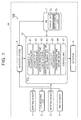
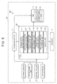
- FIG. 1 is a block diagram showing a vehicle control apparatus according to a first embodiment.
- a vehicle control apparatus 100 shown in FIG. 1 which is mounted in a vehicle M such as a passenger car, controls the running of the vehicle M.
- the vehicle control apparatus 100 for example, performs a lane keeping assist [LTC: Lane Trace Control] of making the vehicle M run along a running lane on which the vehicle M is running.
- the lane keeping assist for example, is a driving assist of controlling a vehicle such that the lateral position of the vehicle is a target lateral position in a running lane, and therewith, when a driver performs a steering, reflecting the steering on the running of the vehicle.
- the lateral position of the vehicle is the position of the vehicle in the width direction of the running lane.
- the target lateral position for example, is set to a central position of the running lane in the width direction of the running lane. Further, the target lateral position may be set to a position that is offset from the central position of the running lane in the width direction of the lane.
- the vehicle control apparatus 100 may perform an automatic driving operation of making the vehicle M automatically run toward a destination that is previously set on a map. That is, the content of the embodiment can be applied also to the vehicle M during the automatic driving.
- the vehicle control apparatus 100 controls the vehicle M such that the vehicle M runs along the running lane in a steering control range and a vehicle speed control range that are previously set when the driver turns on the LTC or the automatic driving.
- the steering control range is a range in which the vehicle control apparatus 100 is allowed to control the steering of the vehicle M in the vehicle control for the LTC or the automatic driving.
- the steering control range for example, includes at least one of the control range of steering angle, the control range of change rate of the steering angle, the control range of steering torque, and the control range of change rate of the steering torque.
- the vehicle speed control range is a range in which the vehicle control apparatus 100 is allowed to control the vehicle speed or acceleration of the vehicle M in the vehicle control for the LTC or the automatic driving.
- the vehicle speed control range for example, includes the control range of the vehicle speed and the control range of the acceleration (deceleration).
- the steering control range and the vehicle speed control range may be fixed ranges, or the ranges may be altered dependent on the alteration of a setting by the driver or the running situation of the vehicle M.
- the vehicle control apparatus 100 computes a departure margin time while controlling the vehicle M such that the vehicle M runs along the running lane.
- the departure margin time is a time (for example, the minimum time) until the vehicle M departs from the running lane in the above-described steering control range and vehicle speed control range. For example, if an abnormality such as a false recognition of a surrounding situation occurs in the vehicle control apparatus 100 and the vehicle control apparatus 100 controls the vehicle M such that the vehicle M goes toward a lane boundary of the running lane within the steering control range and the vehicle speed control range, the departure margin time corresponds to the minimum time until the vehicle M departs from the running lane.
- the departure margin time may be the minimum time until the vehicle M departs from the running lane by the control of the steering from the vehicle control apparatus 100 while the current vehicle speed is maintained.
- the minimum time herein is not the minimum time until the vehicle M actually departs from the running lane, but the computed minimum time until the vehicle M hypothetically departs from the running lane.
- the minimum time varies depending on the computation technique or the setting of parameters to be used for the computation.
- the vehicle control apparatus 100 computes the departure margin time, for example, based on the running state of the vehicle M (the state of vehicle speed, acceleration, yaw rate and the like), the lateral position of the vehicle M relative to the running lane, and the orientation of the vehicle M relative to the running lane (the orientation of the vehicle M relative to a white line forming the running lane).
- the state of departing from the running lane for example, can be a state in which at least a front edge of the vehicle M exceeds the white line (a lane line, a vehicular lane line, or the like) forming the running lane.
- the state of departing from the running lane may be a state in which the vehicle M is on the white line.
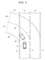
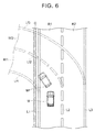
- FIG. 2 is a plan view for describing the departure margin time.
- FIG. 2 shows a running lane R1 along which the vehicle M runs, an adjacent lane R2 that is adjacent to the right side of the running lane R1, white lines L1, L2 that form the running lane R1, and a white line L3 that forms the adjacent lane R2 together with the white line L2.
- FIG. 2 shows a running lane Rf1, an adjacent lame Rf2 and white lines Lf1 to Lf3 in the case where the vehicle control apparatus 100 performs a false recognition hypothetically, and a position Mf of the vehicle M in the case of running along the running lane Rf1.
- FIG. 2 shows a case where, although the actual running lane R1 and the adjacent lane R2 are straight roads, the vehicle control apparatus 100 falsely recognizes the running lane Rf1 and adjacent lane Rf2 that are left-hand curves, to control the vehicle M.
- the running lane Rf1 and the adjacent lane Rf2 are hypothetical lanes that are falsely recognized by the vehicle control apparatus 100 in the case of departing from the actual running lane R1 in the shortest time from the current position of the vehicle M. That is, the running lane Rf1 and the adjacent lane Rf2 vary depending on not only the actual road shape but also the running state of the vehicle M and the steering control range and vehicle speed control range of the vehicle control apparatus 100.
- the vehicle control apparatus 100 does not need to obtain the virtual running lane Rf1 and the adjacent lane Rf2 by computation.
- the vehicle control apparatus 100 computes the departure margin time, based on the running state of the vehicle M, the lateral position of the vehicle M relative to the running lane R1, and the orientation of the vehicle M relative to the running lane R1.
- the vehicle control apparatus 100 for example, computes the departure margin time at a previously set interval, during the execution of the LTC.
- the vehicle control apparatus 100 determines whether the driver is in a hand-release state.
- the hand-release state for example, is a state in which the driver has released his hands from a steering wheel.
- the vehicle control apparatus 100 determines whether the driver is in the hand-release state, based on a signal from a steering touch sensor provided on the steering wheel.
- the vehicle control apparatus 100 may determine that the driver is not in the hand-release state, even when the driver has released his hands from the steering wheel.
- an accelerator pedal operation or a brake pedal operation is detected, the vehicle control apparatus 100 may determine that the driver is not in the hand-release state.
- the vehicle control apparatus 100 In the case of determining that the driver is in the hand-release state, the vehicle control apparatus 100 starts the measurement of a hand-release duration time.
- the hand-release duration time is a time during which the driver continues the hand-release state.
- the vehicle control apparatus 100 estimates a driving return time based on the hand-release duration time.
- the driving return time is a time until the driver in the hand-release state returns to the driving operation.
- the return to the driving operation for example, is that the driver in the hand-release state becomes aware of the abnormality of the vehicle control and holds the steering wheel.
- the return to the driving operation may be that the driver in the hand-release state becomes aware of the abnormality of the vehicle control and performs an operation of canceling the vehicle control such as the LTC.
- the operation of canceling the vehicle control may be an operation of a cancel button by the driver, or may be an override by the driver.
- the override is an operation of canceling the vehicle control, for example, by turning the steering wheel to a previously set steering threshold or more, or by stepping the brake pedal or accelerator pedal to a previously set stepping threshold or more.
- the vehicle control apparatus 100 determines whether a difference resulting from subtracting the driving return time from the departure margin time is less than or equal to a first threshold.
- the difference resulting from subtracting the driving return time from the departure margin time can be a negative value.
- the first threshold is a threshold that is set for outputting an alarm to the driver in the hand-release state at a proper timing.
- the first threshold may be a fixed value, or may be a variable value.
- the first threshold may be zero, or may be a negative value. As the first threshold, for example, a greater value may be adopted as the vehicle speed of the vehicle M or the acceleration of the vehicle M increases.
- a greater value may be adopted as the first threshold, compared to the case where the road shape is a straight shape.
- a greater value as the first threshold, it is possible to advance the timing of the alarm.
- Increasing the first threshold is equivalent to shortening the departure margin time by the weighting of the departure margin time.
- the vehicle control apparatus 100 In the case of determining that the difference resulting from subtracting the driving return time from the departure margin time is the less than or equal to first threshold, the vehicle control apparatus 100 outputs the alarm to the driver in the hand-release state.
- the alarm for example, is a voice output or an image display that prompts the driver to hold the steering wheel.
- the vehicle control apparatus 100 may perform an extension control of the departure margin time.
- the extension control of the departure margin time for example, is a control of extending the departure margin time by at least one of the deceleration of the vehicle M and the restriction of the steering control range.
- the restriction of the steering control range for example, is to narrow the range of the steering torque control by the vehicle control apparatus 100 and the range of the steering torque change rate control by the vehicle control apparatus 100.
- the restriction of the steering control range may be to narrow the range of the steering angle control and the range of the steering angle change rate control.
- both of the deceleration of the vehicle M and the restriction of the steering control range may be performed as the extension control of the departure margin time.
- the second threshold may be a fixed value, or may be a variable value.
- the second threshold may be zero, or may be a negative value.
- the second threshold may be the same value as the first threshold. In this case, the vehicle control apparatus 100 executes the extension control of the departure margin time, simultaneously with the output of the alarm.
- the second threshold may be a value less than the first threshold.
- the vehicle control apparatus 100 executes the extension control of the departure margin time, when the driver continues the hand-release state even after the output of the alarm and the vehicle control apparatus 100 determines that the difference resulting from subtracting the driving return time from the departure margin time is less than or equal to the second threshold.
- the extension control of the departure margin time is not repeated unlimitedly, but for example, is executed only once or twice for one continuation of the hand-release state of the driver.
- the extension control of the departure margin time may be performed repeatedly until the number of times reaches a previously set number, or may be performed repeatedly until the speed of the vehicle M becomes a previously set speed (for example, 40 km/h) or less.
- the vehicle control apparatus 100 may perform the extension control of the departure margin time before the output of the alarm. That is, the second threshold may be a value greater than the first threshold.
- the vehicle control apparatus 100 for example, performs the extension control of the departure margin time only once. Thereafter, in the case of determining that the difference resulting from subtracting the driving return time from the departure margin time is less than or equal to the first threshold, the vehicle control apparatus 100 outputs the alarm.
- the vehicle control apparatus 100 includes an external sensor 1, a GPS [Global Positioning System] receiving unit 2, an internal sensor 3, a map database 4, a navigation system 5, an actuator 6, an HMI [Human Machine Interface] 7, and an ECU [Electronic Control Unit] 10.
- the external sensor 1 is detection equipment to detect the external situation that is the surrounding information of the vehicle M.
- the external sensor 1 includes at least a camera.
- the camera for example, is provided on the back side of a windshield of the vehicle M.
- the camera sends the imaging information relevant to the external situation of the vehicle M, to the ECU 10.
- the camera may be a monocular camera, or may be a stereo camera.
- the stereo camera includes two imaging units arranged such that binocular parallax is reproduced.
- the external sensor 1 may include a radar or a LIDAR [Laser Imaging Detection and Ranging].
- the radar detects an obstacle outside the vehicle M, using a radio wave (for example, a millimeter wave).
- the radar detects the obstacle by sending the radio wave around the vehicle M and receiving the radio wave reflected by the obstacle.
- the radar sends the detected obstacle information to the ECU 10.
- the LIDAR detects an obstacle outside the vehicle M, using light.
- the LIDAR detects the obstacle by sending light around the vehicle M and receiving the light reflected by the obstacle to measure the distance to the obstacle.
- the LIDAR sends the detected obstacle information to the ECU 10.
- the GPS receiving unit 2 receives signals from three or more GPS satellites, and thereby, measures the position of the vehicle M (for example, the latitude and longitude of the vehicle M).
- the GPS receiving unit 2 sends the measured position information about the vehicle M, to the ECU 10.
- other means that can identify the latitude and longitude of the vehicle M may be used, instead of the GPS receiving unit 2.
- the internal sensor 3 is detection equipment to detect the running state of the vehicle M and the driving operation by the driver.
- the internal sensor 3, for example, includes a speed sensor, an acceleration sensor and a yaw rate sensor.
- the speed sensor is a detector to detect the speed of the vehicle M.
- a wheel speed sensor that is provided at a wheel of the vehicle M, a drive shaft to rotate integrally with the wheel or the like and that detects the rotational speed of the wheel is used.
- the speed sensor sends the detected vehicle speed information (wheel speed information), to the ECU 10.
- the acceleration sensor is a detector to detect the acceleration of the vehicle M.
- the acceleration sensor for example, includes a front-back acceleration sensor to detect the acceleration in the front-back direction of the vehicle M, and a lateral acceleration sensor to detect the lateral acceleration of the vehicle M.
- the acceleration sensor sends the acceleration information about the vehicle M, to the ECU 10.
- the yaw rate sensor is a detector to detect the yaw rate (rotational angular velocity) around the vertical axis of the gravity center of the vehicle M.
- a gyro sensor can be used.
- the yaw rate sensor sends the detected yaw rate information about the vehicle M, to the ECU 10.
- the internal sensor 3 for example, includes a steering torque sensor, a steering angle sensor, a steering touch sensor, an accelerator pedal sensor, and a brake pedal sensor.
- the steering torque sensor and the steering angle sensor which are provided at a steering shaft of the vehicle M, detect the steering torque given to the steering wheel by the driver and the steering angle of the steering wheel, respectively. It is only necessary to include one of the steering torque sensor and the steering angle sensor.
- the steering touch sensor which is provided on the steering wheel of the vehicle M, detects the contact of the driver with the steering wheel and the holding pressure of the driver on the steering wheel.
- a pressure-sensitive sensor can be used as the steering touch sensor. The steering torque sensor, the steering angle sensor and the steering touch sensor send the detected steering information about the steering by the driver, to the ECU 10.
- the accelerator pedal sensor which is provided at a shaft part of the accelerator pedal, detects the stepping quantity to the accelerator pedal (the position of the accelerator pedal).
- the accelerator pedal sensor sends a signal corresponding to the detected stepping quantity of the accelerator pedal, to the ECU 10.
- the brake pedal sensor which is provided at a shaft part of the brake pedal, detects the stepping quantity to the brake pedal (the position of the brake pedal).
- the operation force to the brake pedal (the stepping force to the brake pedal, the pressure of a master cylinder or the like) may be detected.
- the brake pedal sensor sends the brake operation information relevant to the detected stepping quantity or operation quantity to the brake pedal, to the ECU 10.
- the internal sensor 3 may include a shift lever sensor to detect the operation of a shift lever, and may include a direction indicator sensor to detect the operation of a direction indicator.
- the internal sensor 3 may include a driver monitoring camera to image the driver.
- the driver monitoring camera for example, is provided at a position that is on a cover of a steering column of the vehicle M and that is in front of the driver. Multiple driver monitoring cameras may be provided for imaging the driver from multiple directions. The driver monitoring camera sends the imaging information about the driver, to the ECU 10.
- the map database 4 is a database including map information.
- the map database for example, is formed in an HDD [Hard Disk Drive] that is mounted in the vehicle.
- the map information for example, includes the position information about roads, the information about road shapes (for example, types of curves and straight parts, curvatures of curves or the like), and the position information about intersections and crossroads.
- the map information may include the width information about roads, and may include the position information about shield structures such as buildings and walls.
- the map database 4 does not always need to be mounted in the vehicle M, and may be stored in a computer that is in a facility such as an information processing center and that can communicate with the vehicle M.
- the navigation system 5 is an apparatus to guide the driver of the vehicle M, to a destination set by the driver of the vehicle M.
- the navigation system 5 calculates a route along which the vehicle M runs, based on the position information about the vehicle M measured by the GPS receiving unit 2 and the map information of the map database 4. As the route, an appropriate lane may be specified in a section of multiple lanes.
- the navigation system 5, for example, computes a target route from the position of the vehicle M to the destination, and informs the driver of the target route by the indication on a display or the voice output from a speaker.
- the target route may include the information about sections at which the vehicle M should perform lane change.
- the navigation system 5, for example, sends the information about the target route for the vehicle M, to the ECU 10.
- the navigation system 5 is used, for example, when the vehicle control apparatus 100 performs the automatic driving.
- the navigation system 5 may include a communication unit to perform wireless communication with other vehicles or facilities such as information processing centers.
- the vehicle control apparatus 100 does not always need to include the navigation system 5.
- the actuator 6 is equipment to execute the running control of the vehicle M.
- the actuator 6 includes, at least, a throttle actuator, a brake actuator and a steering actuator.
- the throttle actuator controls the supply rate of air for an engine (throttle opening angle) in response to a control signal from the ECU 10, and controls the driving force of the vehicle M.
- the throttle actuator is not included, and the control signal from the ECU 10 is input to a motor that is a dynamic power source, so that the driving force is controlled.
- the brake actuator controls a brake system in response to a control signal from the ECU 10, and controls the braking force that is given to wheels of the vehicle M.
- a brake system for example, a hydraulic brake system can be used.
- the steering actuator controls the drive of an assist motor that is part of an electric power steering system and that controls the steering torque, in response to a control signal from the ECU 10. Thereby, the steering actuator controls the steering torque of the vehicle M.
- the HMI 7 is an interface for performing the input and output of information between the driver and the vehicle control apparatus 100.
- the HMI 7 is an interface for performing the input and output of information between an occupant (including the driver) in the vehicle M and the vehicle control apparatus 100.
- the display unit 7a may be configured by multiple kinds of displays.
- the display unit 7a includes at least one of a MID of a combination meter, a center display of an instrument panel, a HUD [Head Up Display], a glass-type wearable display that the driver wears, and the like.
- the display unit 7a displays the image information in response to a control signal from the ECU 10.
- the voice output unit 7b is a speaker for giving notice to the driver by the output of alarm sound or voice.
- the voice output unit 7b may be configured by multiple speakers, and may be configured to include a speaker fixed to the vehicle M.
- the voice output unit 7b includes at least one of a speaker provided on the back side of the instrument panel of the vehicle M, a speaker provided on the inner side of a door at a driver seat in the vehicle M, and the like.
- the voice output unit 7b outputs the alarm sound or voice to the driver, in response to a control signal from the ECU 10.
- the display unit 7a and the voice output unit 7b do not always need to constitute a part of the HMI 7.
- the ECU 10 is an electronic control unit including a CPU [Central Processing Unit], a ROM [Read Only Memory], a RAM [Random Access Memory], and the like.
- a program stored in the ROM is loaded into the RAM and is executed by the CPU, and thereby, various controls are executed.
- the ECU 10 may be configured by multiple electronic control units. Here, some of the functions of the ECU 10 may be performed by a computer that is in a facility such as an information processing center and that can communicate with the vehicle M.
- the ECU 10 includes a running state recognition unit 11, a lateral position recognition unit 12, a departure margin time computation unit 13, a hand-release duration time measurement unit 14, a driver state recognition unit 15, a driving return time estimation unit 16, and a control unit 17.
- the running state recognition unit 11 recognizes the running state of the vehicle M, based on the detection result of the internal sensor 3.
- the running state of the vehicle M includes at least the vehicle speed of the vehicle M and the yaw rate of the vehicle M.
- the running state of the vehicle M may include the acceleration (deceleration) of the vehicle M.
- the running state recognition unit 11, for example, recognizes the vehicle speed of the vehicle M, based on the vehicle speed information of the speed sensor.
- the running state recognition unit 11, for example, recognizes the yaw rate of the vehicle M, based on the yaw rate information of the yaw rate sensor.
- the lateral position recognition unit 12 recognizes the lateral position of the vehicle M relative to the running lane R1 and the orientation of the vehicle M relative to the running lane R1, based on the detection result of the external sensor 1.
- the lateral position recognition unit 12, for example, recognizes the white lines L1, L2 of the running lane R1, based on the imaging information of the camera.
- the lateral position recognition unit 12, for example, recognizes the lateral position that is the intervals in the lateral direction (the width direction of the running lane R1) between the white lines L1, L2 and the vehicle M, based on the imaging information of the camera, by a well-known image processing technique.
- the lateral position recognition unit 12 recognizes the orientation of the vehicle M relative to the running lane R1 (the orientation of the vehicle M relative to the white line L1 or the white line L2), based on the imaging information of the camera, by a well-known image processing technique.
- the lateral position recognition unit 12 does not always need to use the imaging information of the camera, and may use the white line recognition by the radar.
- the departure margin time computation unit 13 computes the departure margin time, which is the time until the vehicle M departs from the running lane R1 within the steering control range and the vehicle speed control range.
- the departure margin time computation unit 13, for example, computes the departure margin time, based on the running state of the vehicle M and the lateral position and orientation of the vehicle M relative to the running lane R1.
- the departure margin time computation unit 13, for example, computes the departure margin time, by combining well-known techniques (an optimization technique and the like).
- the departure margin time computation unit 13 computes the departure margin time with reference to the current steering control range and the vehicle speed control range.
- the departure margin time computation unit 13 may compute the departure margin time, based on the shape of a road in front of the vehicle M. Furthermore, the departure margin time computation unit 13 may compute the departure margin time, based on the road width of the running lane R1 and the curvature of the running lane R1. The departure margin time computation unit 13, for example, recognizes the road width of the running lane R1 and the curvature of the running lane R1, based on the position information about the vehicle M and the map information.
- the departure margin time computation unit 13 may perform the computation for both a case where the vehicle M departs from the white line L1 on the left side of the running lane R1 and for a case where the vehicle M departs from the white line L2 on the right side of the running lane R1. In this case, for example, the departure margin time computation unit 13 adopts the shorter one of the times, as the departure margin time. Further, the departure margin time computation unit 13 may recognize the closer white line to the vehicle M, of the white line L1 and the white line L2, based on the lateral position of the vehicle M relative to the running lane R1, and may compute the departure margin time for the case where the vehicle M departs from the white line closer to the vehicle M.
- the hand-release duration time measurement unit 14 measures the hand-release duration time for the driver. First, the hand-release duration time measurement unit 14 determines whether the driver is in the hand-release state, based on the detection result of the internal sensor 3. The hand-release duration time measurement unit 14, for example, determines whether the driver is in the hand-release state, based on the detection result of the steering touch sensor. In the case of recognizing that the driver is not holding the steering wheel, from the detection result of the steering touch sensor, the hand-release duration time measurement unit 14 determines that the driver is in the hand-release state.
- the hand-release duration time measurement unit 14 may determine that the driver is not in the hand-release state, when the driving operation by the driver is detected based on detection results of the accelerator pedal sensor, the brake pedal sensor and the like.
- the driving operation may include the operation of the shift lever and the operation of the direction indicator.
- the driving operation can include the input operation to the navigation system 5 and the input operation to the HMI 7.
- the hand-release duration time measurement unit 14 may determine that the driver in the hand-release state, in the case of recognizing that the driver is not performing any driving operation based on the detection results of the steering torque sensor, the accelerator pedal sensor and the brake pedal sensor. In this case, the steering touch sensor is unnecessary.
- the hand-release duration time measurement unit 14 starts the measurement of the hand-release duration time, which is a time during which the driver continues the hand-release state.
- the hand-release duration time measurement unit 14 completes the measurement of the hand-release duration time.
- the driver state recognition unit 15 recognizes the state of the driver.
- the driver state recognition unit 15 for example, recognizes whether the driver is in a low awake state, based on the imaging information of the driver monitoring camera.
- the low awake state for example, is a state in which the driver is in a daze because of sleep deprivation or the like.
- the low awake state also includes a sleep state.
- the driver state recognition unit 15 can recognize, by a well-known technique, whether the driver is in the low awake state, based on the eye-opening condition and other conditions of the driver that are obtained from the imaging information of the driver monitoring camera.
- the driver state recognition unit 15 may recognize whether the driver is in the low awake state, from the heartbeat information or brain wave information about the driver that is acquired, through wireless communication, by the communication with a wearable device worn by the driver or a portable information terminal.
- the driver state recognition unit 15 can recognize, by a well-known technique, whether the driver is in the low awake state, based on a variety of information.
- the driver state recognition unit 15 recognizes whether the driver is in a look-away state, based on the imaging information of the driver monitoring camera.
- the look-away state for example, is a state in which the driver orients his face in a direction other than the forward direction of the vehicle M.
- the driver state recognition unit 15 can recognize whether the driver is in the look-away state, for example, by performing an eye-gaze detection for the driver from the imaging information of the driver monitoring camera by a well-known technique. In the case of recognizing that the driver is operating a portable information terminal by the communication with the portable information terminal through wireless communication, the driver state recognition unit 15 may recognize that the driver is in the look-away state.
- the driver state recognition unit 15 can recognize, by a well-known technique, whether the driver is in the look-away state, based on a variety of information.
- the driver state recognition unit 15 may recognize the posture of the driver.
- the driver state recognition unit 15, for example, recognizes whether the posture of the driver is an appropriate posture to the driving operation, based on the imaging information of the driver monitoring camera.
- the driver state recognition unit 15 recognizes whether the posture of the driver is an appropriate posture to the driving operation, for example, from the positions of the driver's legs and the angle of the backrest of the seat. For example, in the case where the driver crosses his legs, the driver state recognition unit 15 recognizes that the posture of the driver is not an appropriate posture to the driving operation. In the case where the driver holds a portable information terminal in his hand, the driver state recognition unit 15 may recognize that the posture of the driver is not an appropriate posture to the driving operation.
- the driver state recognition unit 15 may determine a driver type of the driver.
- the driver type for example, includes a driver type that likes fast running (for example, a sporty type), and an ordinary driver type (for example, a normal type).
- a driver type that likes fast running for example, as a driving tendency of the driver, the frequency of the lane change for passing is high when the driver performs the driving operation of the vehicle M.
- the driver state recognition unit 15, for example determines the driver type of the driver based on a past driving history for the driver.
- the driver state recognition unit 15 may determine the driver type of the driver, based on the setting that is input by the driver in advance.
- the ECU 10 does not always need to include the driver state recognition unit 15.
- the driving return time estimation unit 16 estimates the driving return time, based on the hand-release duration time measured by the hand-release duration time measurement unit 14.
- the driving return time estimation unit 16 estimates the driving return time from the hand-release duration time, using map data or a numerical formula that is previously stored.
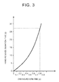
- FIG. 3 is a graph specifying a relationship between the hand-release duration time and the driving return time.
- the ordinate indicates the hand-release duration time (unit: second)
- the abscissa indicates the driving return time (unit: second).
- the driving return time estimation unit 16 uses the relationship of the graph shown in FIG. 3 as the map data, and thereby, estimates the driving return time from the hand-release duration time.
- the driving return time can be evaluated as 0.8 seconds.
- the driving return time estimation unit 16 may estimate the driving return time, using the recognition result of the driver state recognition unit 15, in addition to the hand-release duration time. For example, in the case where the driver is recognized to be in the low awake state by the driver state recognition unit 15, the driving return time estimation unit 16 estimates the driving return time to be longer than in the case where the driver is recognized not to be in the low awake state.
- the driving return time estimation unit 16 may adopt a mode of adding a previously set delay time to the driving return time in the case where the driver is recognized to be in the low awake state.
- the driving return time estimation unit 16 estimates the driving return time to be longer than in the case where the driver is recognized not to be in the look-away state.
- the driving return time estimation unit 16 may adopt a mode of adding a previously set delay time to the driving return time in the case where the driver is recognized to be in the look-away state.
- the driving return time estimation unit 16 may estimate the driving return time to be longer than in the case where the posture of the driver is determined to be an appropriate posture to the driving operation.
- the driving return time estimation unit 16 may adopt a mode of adding a previously set delay time to the driving return time in the case where the posture of the driver is determined not to be an appropriate posture to the driving operation.
- the driving return time estimation unit 16 may estimate the driving return time in consideration of the driver type.
- the driving return time estimation unit 16 uses different kinds of map data between the case where the driver is the driver type that likes fast running and the case where the driver is the ordinary driver type.
- the driving return time estimation unit 16 can use, for example, the map data corresponding to FIG. 3 .
- the driving return time estimation unit 16 can use map data that is lower than the map data corresponding to the increase rate of the driving return time relative to the hand-release duration time in FIG. 3 , because it seems that the driver returns to the driving operation at a quicker speed in response to the alarm.
- the driving return time estimation unit 16 may alter the map data depending on the frequency of the hand-release state of the driver. For example, in the case where the driver repeats the hand-release state at a frequency of a certain number of times or more in a unit period, the driving return time estimation unit 16 can use map data that is higher in the increase rate of the driving return time relative to the hand-release duration time, compared to the case where the driver does not repeat the hand-release state at the frequency of the certain number of times or more in the unit period.
- the control unit 17 determines whether the difference between the departure margin time computed by the departure margin time computation unit 13 and the driving return time estimated by the driving return time estimation unit 16 is less than or equal to the first threshold. In the case of determining that the difference resulting from subtracting the driving return time from the departure margin time is less than or equal to the first threshold, the control unit 17 outputs the alarm to the driver.
- the control unit 17, for example, sends a control signal to the HMI 7, and thereby, outputs an alarm by the image display of the display unit 7a and an alarm by the voice output of the voice output unit 7b.
- the alarms for example, are the image display and voice output having a content that prompts the driver to hold the steering wheel.
- the alarm may be either one of the image display and the voice output.
- the control unit 17 may output the alarm through the portable information terminal.
- control unit 17 may output the alarm multiple times.
- the control unit 17 may set multiple thresholds that are less than the first threshold, and may output the alarm whenever the difference resulting from subtracting the driving return time from the departure margin time becomes equal to or less than any one of the thresholds.
- control unit 17 determines whether the difference resulting from subtracting the driving return time from the departure margin time is less than or equal to the second threshold. In the case of determining that the difference resulting from subtracting the driving return time from the departure margin time is less than or equal to the second threshold, the control unit 17 executes the extension control of the departure margin time by at least one of the deceleration of the vehicle M and the restriction of the steering control range. The control unit 17 executes the extension control of the departure margin time, for example, by sending a control signal to the actuator 6.
- control unit 17 may execute the extension control of the departure margin time by the restriction of the steering control range, only in the case of determining that the steering of the vehicle M is necessary because the vehicle M departs from the running lane R1 in the minimum time. Further, the control unit 17 may decide the execution content of the extension control of the departure margin time, based on the road shape of the running lane R1.
- control unit 17 may execute the extension control of the departure margin time not by the restriction of the steering control range but by the deceleration of the vehicle M, in order to avoid the restriction of the steering control range from interfering with the curve running of the vehicle M.
- the control unit 17 may execute the extension control of the departure margin time, simultaneously with the output of the alarm described above. In this case the same value can be adopted, as both the second threshold and the first threshold. Alternatively, as the second threshold, a value less than the first threshold may be adopted, and the control unit 17 may execute the extension control of the departure margin time, in the case where the driver continues the hand-release state even after the alarm. As the second threshold, a value greater than the first threshold may be adopted, and the control unit 17 may execute the extension control of the departure margin time before the alarm. In this case, for example, after executing the extension control of the departure margin time once, the control unit 17 does not perform the extension control of the departure margin time, even when the above difference again becomes less than or equal to the second threshold.
- control unit 17 may execute the extension control of the departure margin time multiple times. In this case, the control unit 17 may output the alarm whenever executing the extension control of the departure margin time.
- the control unit 17 may repeat the extension control of the departure margin time until the number of times reaches a previously set number (for example, twice), or may repeat the extension control of the departure margin time until the speed of the vehicle M becomes a previously set speed (for example, 40 km/h) or less.
- the control unit 17 outputs the alarm to the driver.
- the control unit 17 does not need to output the alarm immediately, and may output the alarm after the elapse of a certain time. Further, in the case of determining that the difference resulting from subtracting the driving return time from the departure margin time is less than or equal to the first threshold, the control unit 17 may execute the extension control of the departure margin time first, and may output the alarm in time with the completion of the extension control of the departure margin time. Here, the control unit 17 does not always need to perform the extension control of the departure margin time.
- the control unit 17 may alter the first threshold.
- the control unit 17, for example, alters the first threshold depending on the vehicle speed of the vehicle M.
- the control unit 17 may set the first threshold to a greater value as the vehicle speed of the vehicle M increases.
- the control unit 17 alters the first threshold depending on the acceleration of the vehicle M.
- the control unit 17 may set the first threshold to a greater value as the acceleration of the vehicle M increases.
- the control unit 17 may alter the first threshold depending on the road shape. For example, in the case where the shape of a road along which the vehicle M is running is a curve shape, the control unit 17 sets a greater value, compared to the case where the road shape is a straight shape.
- control unit 17 may alter the first threshold, based on the recognition result of the driver state recognition unit 15. For example, in the case where the driver is recognized to be in the low awake state by the driver state recognition unit 15, the control unit 17 sets the first threshold to a greater value, compared to the case where the driver is recognized not to be in the low awake state. Similarly, for example, in the case where the driver is recognized to be in the look-away state by the driver state recognition unit 15, the control unit 17 sets the first threshold to a greater value, compared to the case where the driver is recognized not to be in the look-away state.
- the control unit 17 may perform the above-described alterations of the threshold, for the second threshold.
- the control unit 17 may cancel the vehicle control for the LTC or the automatic driving. For example, in the case where the difference resulting from subtracting the driving return time from the departure margin time is less than or equal to a fourth threshold, the control unit 17 cancels the vehicle control for the LTC or the automatic driving, and stops the vehicle M at a road shoulder.
- the fourth threshold is a value that is less than the first threshold and the second threshold.
- a value that is greater in absolute value is smaller as the threshold.
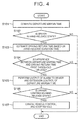
- FIG. 4 is a flowchart showing a control method by the vehicle control apparatus 100 according to the first embodiment.
- the flowchart shown in FIG. 4 is executed repeatedly at a previously set interval, in the case where the vehicle M is controlled such that the vehicle M runs along the running lane R1.
- step S101 the ECU 10 performs the computation of the departure margin time by the departure margin time computation unit 13.
- the departure margin time computation unit 13 computes the departure margin time, which is the time (for example, the minimum time) until the vehicle M departs from the running lane within the steering control range and the vehicle speed control range.
- the departure margin time computation unit 13 computes the departure margin time, for example, based on the running state of the vehicle M and the lateral position and orientation of the vehicle M relative to the running lane R1. After computing the departure margin time, the ECU 10 transitions to step S102.
- step S102 the ECU 10 determines whether the driver is in the hand-release state by the hand-release duration time measurement unit 14.
- the hand-release duration time measurement unit 14 determines whether the driver is in the hand-release state, based on the detection result of the steering touch sensor. In the case of determining that the driver is not in the hand-release state (S102: NO), the ECU 10 finishes the process this time. Thereafter, the process is repeated again from step S101, after the elapse of a previously set time. In the case of determining that the driver is in the hand-release state (S102: YES), the ECU 10 starts the measurement of the hand-release duration time by the hand-release duration time measurement unit 14, and transitions to step S103.
- the hand-release duration time measurement unit 14 does not start the measurement of the hand-release duration time anew, and continues the current measurement of the hand-release duration time.
- the ECU 10 performs the estimation of the driving return time by the driving return time estimation unit 16.
- the driving return time estimation unit 16 estimates the driving return time from the hand-release duration time, using map data or a numerical formula that is previously stored.
- the driving return time estimation unit 16 may estimate the driving return time, using the recognition result of the driver state recognition unit 15, in addition to the hand-release duration time. For example, in the case where the driver is recognized to be in the low awake state by the driver state recognition unit 15, the driving return time estimation unit 16 estimates the driving return time to be a longer time, compared to the case where the driver is recognized not to be in the low awake state.
- the driving return time estimation unit 16 estimates the driving return time to be a longer time, compared to the case where the driver is recognized not to be in the look-away state.
- the driving return time estimation unit 16 may estimate the driving return time in consideration of the driver type.
- the driving return time estimation unit 16 estimates the driving return time, using different kinds of map data between the case where the driver is the driver type that likes fast running and the case where the driver is the ordinary driver type. After the driving return time estimation unit 16 estimates the driving return time, the ECU 10 transitions to step S104.
- step S104 the ECU 10 determines whether the difference resulting from subtracting the driving return time from the departure margin time is less than or equal to the first threshold, by the control unit 17.
- the control unit 17 may alter the first threshold. For example, the control unit 17 increases the first threshold as the vehicle speed of the vehicle M increases, and thereby, advances the timing of the alarm output. Increasing the first threshold is equivalent to shortening the departure margin time by the weighting of the departure margin time.
- step S104: NO the ECU 10 finishes the process this time. Thereafter, the process is repeated again from step S101, after the elapse of the previously set time.
- step S104 YES
- the ECU 10 transitions to step S105.
- step S105 the ECU 10 performs the output of the alarm by the control unit 17.
- the control unit 17, for example, sends a control signal to the HMI 7, and thereby, outputs the alarm by the image display of the display unit 7a and the alarm by the voice output of the voice output unit 7b. Further, simultaneously with the output of the alarm, the control unit 17 executes the extension control of the departure margin time by at least one of the deceleration of the vehicle M and the restriction of the steering control range.
- the case of simultaneously performing the output of the alarm and the extension control of the departure margin time in this way corresponds to the case where the first threshold relevant to the alarm output and the second threshold relevant to the extension control of the departure margin time are the same value, for example.
- control unit 17 may set different values as the first threshold and the second threshold, and may provide a time lag between the alarm output and the extension control of the departure margin time.
- the ECU 10 After executing the output of the alarm and the extension control of the departure margin time, the ECU 10 transitions to step S106.
- the ECU 10 may transition to step S106, after the elapse of a previously set time from the execution of the output of the alarm and the execution of the extension control of the departure margin time.
- the ECU 10 does not always need to perform the extension control of the departure margin time.
- step S106 again, the ECU 10 determines whether the driver is continuing the hand-release state, by the hand-release duration time measurement unit 14. In the case of determining that the driver is not continuing the hand-release state (S106: NO), the ECU 10 finishes the process this time. Thereafter, the process is repeated again from step S101, after the elapse of a previously set time. In the case of determining that the driver is continuing the hand-release state (S106: YES), the ECU 10 transitions to step S107.
- step S107 the ECU 10 cancels the vehicle control for the LTC or the automatic driving by the control unit 17, and stops the vehicle M at a road shoulder.
- the control unit 17 sends a control signal to the actuator 6, and thereby, stops the vehicle M at a road shoulder of the running lane R1.
- the ECU 10 may cancel the vehicle control of the LTC or the automatic driving and stop the vehicle M at a road shoulder, in case where the difference resulting from subtracting the driving return time from the departure margin time is less than or equal to the fourth threshold, instead of steps S106 and S107.
- the fourth threshold is a value that is less than the first threshold. Further, it is not always necessary to perform steps S106 and S107.
- the ECU 10 may execute step S102 before step S101, and may execute step S102 and step S103 before step S101. In this case, the ECU 10 computes the departure margin time, in the case of determining that the driver is in the hand-release state.
- the hand-release duration time measurement unit 14 repeats the determination of whether the driver is in the hand-release state, at a previously set interval, separately from the flowchart shown in FIG. 4 . In the case of determining that the driver is not in the hand-release state, the hand-release duration time measurement unit 14 completes the measurement of the hand-release duration time. In the case where the hand-release duration time measurement unit 14 during the measurement of the hand-release duration time determines that the driver is not in the hand-release state, the ECU 10 finishes the process of the flowchart shown in FIG. 4 . In the case of determining that the driver is not in the hand-release state, the ECU 10 finishes the process of the flowchart shown in FIG.
- step S101 the ECU 10 repeats the process again from step S101, after the elapse of a previously set time.
- the alarm is output to the driver.
- the vehicle control apparatus 100 it is possible to output the alarm at a timing that is scheduled in terms of the departure of the vehicle M from the running lane R1, and to prevent the alarm from giving the driver a feeling of strangeness, compared to the related apparatus that outputs the alarm in a given time in the case where the driver is in the hand-release state.
- the vehicle control apparatus 100 may execute the extension control of the departure margin time by at least one of the deceleration of the vehicle M and the restriction of the steering control range.
- the vehicle control apparatus 100 executes the extension control of the departure margin time when the difference resulting from subtracting the driving return time from the departure margin time is less than or equal to the second threshold, it is possible to ensure that there is time for the driver to return to the driving operation before the vehicle M departs from the running lane, even when an abnormality such as a false recognition occurs in the apparatus while the driver continues the hand-release state for example.
- the vehicle control apparatus 100 may estimate the driving return time to be a longer time, compared to the case where the driver is recognized not to be in the low awake state. In this case, since the time to return to the driving operation in response to the alarm is long when the driver is in the low awake state, the vehicle control apparatus 100 estimates the driving return time to be a longer time when the driver is recognized to be in the low awake state. Thereby, it is possible to estimate the driving return time corresponding to the state of the driver.
- FIG. 5 is a block diagram showing the vehicle control apparatus 101 according to the second embodiment.
- the vehicle control apparatus 101 according to the second embodiment is different from the vehicle control apparatus 100 according to the first embodiment, in that a contact margin time is used instead of the departure margin time.
- the contact margin time is a time (for example, the minimum time) until the vehicle M comes into contact with an obstacle around the vehicle M in a steering control range and a vehicle speed control range that are previously set.
- the obstacle is a structure such as a wall or a building, another vehicle (a leading vehicle, another vehicle running side by side, a two-wheel vehicle, a bicycle or the like), or a pedestrian.
- the contact between the vehicle M and the obstacle may include a case where the distance between the vehicle M and the obstacle becomes equal to or less than a previously set contact distance, in addition to a case where the vehicle M and the obstacle actually come into contact with each other.
- the previously set contact distance may be a fixed value (for example, 0.5 m), or may be a variable value.
- the contact margin time corresponds to the minimum time until the vehicle M comes into contact with the obstacle.
- the contact margin time may be the minimum time until the vehicle M comes into contact with the obstacle by the control of the steering from the vehicle control apparatus 101 while the current vehicle speed is maintained.
- the minimum time herein is not the actual minimum time until the vehicle M comes into contact with the obstacle, but the hypothetical computed minimum time until the vehicle comes into contact with the obstacle. The minimum time varies depending on computation technique or the setting of parameters to be used for the computation.
- FIG. 6 is a plan view for describing the contact margin time.
- FIG. 6 is different from FIG. 2 only in that there is a wall G as the obstacle.
- FIG. 6 shows a situation in which the wall G cannot be recognized due to an abnormality of the radar or the like, and by a false recognition of white lines, the vehicle control apparatus 101 controls the vehicle M such that the vehicle M goes toward the wall G.
- the vehicle control apparatus 101 for example, computes the contact margin time that is the minimum time until the vehicle M comes into contact with the wall G within the steering control range and the vehicle speed control range.
- FIG. 7 is a plan view for describing another example of the contact margin time.
- FIG. 7 shows another vehicle N that runs along the adjacent lane R2, a future position Nf of the other vehicle N that will go straight along the adjacent lane R2, and a position Mf of the vehicle M in the case of running along the running lane Rf1.
- the vehicle control apparatus 101 falsely recognizes the running lane Rf1 and adjacent lane Rf2 that are right-hand curves. Further, FIG.
- the vehicle control apparatus 101 controls the vehicle M such that the vehicle M goes toward the future position Nf of the other vehicle N.
- the vehicle control apparatus 101 for example, computes the contact margin time that is the minimum time until the vehicle M comes into contact with the other vehicle N within the steering control range and the vehicle speed control range.
- the vehicle control apparatus 101 may predict the course of the other vehicle N for computing the contact margin time, but does not have to predict the course of the other vehicle N.
- the vehicle control apparatus 101 may compute the contact margin time using the course information about the other vehicle N. Further, the vehicle control apparatus 101 may determine whether there is a possibility that the vehicle M comes into contact with the other vehicle N by the control that the vehicle control apparatus 101 performs within the steering control range and the vehicle speed control range.
- the vehicle control apparatus 101 computes the contact margin time in the case of determining that there is a possibility that the vehicle M comes into contact with the other vehicle N, and does not compute the contact margin time in the case of determining that there is no possibility that the vehicle M comes into contact with the other vehicle N.
- the vehicle control apparatus 101 may compute the contact margin time, by regarding the other vehicle N as a wall that extends along the adjacent lane R2, without predicting the course of the other vehicle N.
- the vehicle control apparatus 101 may compute the contact margin time to the number of obstacles that are present around the vehicle M. In this case, for example, the vehicle control apparatus 101 outputs the alarm using only the shortest contact margin time, in order to avoid the driver from being irritated by the repetition of the alarm.
- the vehicle control apparatus 101 determines whether the difference between the hand-release duration time and the contact margin time is less than or equal to a third threshold.
- the third threshold is a threshold that is set for outputting the alarm to the driver in the hand-release state at a proper timing.
- the third threshold may be a fixed value, or may be a variable value.
- the third threshold may be zero, or may be a negative value. As the third threshold, for example, a greater value may be adopted as the vehicle speed of the vehicle M or the acceleration of the vehicle M increases.
- a greater value may be adopted as the third threshold, compared to the case where the road shape is a straight shape.
- a greater value may be adopted as the third threshold, compared to the case where the road shape is a straight shape.
- Increasing the third threshold is equivalent to shortening the contact margin time by the weighting of the contact margin time.
- the vehicle control apparatus 101 may perform the extension control of the contact margin time by at least one of the deceleration of the vehicle M and the restriction of the steering control range.
- the second threshold may be the same value as the third threshold.
- the second threshold may be a value greater than the third threshold, or may be a value less than the third threshold.
- an ECU 20 of the vehicle control apparatus 101 is different from that in the first embodiment, in that an obstacle information acquisition unit 21 is included instead of the lateral position recognition unit 12 and in that a contact margin time computation unit 22 is included instead of the departure margin time computation unit 13.
- the obstacle information acquisition unit 21, acquires the obstacle information relevant to an obstacle around the vehicle M, based on the detection result of the external sensor 1.
- the obstacle information for example, includes the information relevant to the position of the obstacle and the size of the obstacle.
- the obstacle information may include the information relevant to the kind of the obstacle (the kind of a structure, another vehicle, a pedestrian or the like).
- the obstacle information acquisition unit 21 can acquire the information relevant to the kind of the obstacle, based on the imaging information of the camera, by a well-known technique.
- the obstacle information acquisition unit 21 may acquire the obstacle information, through wireless communication, from a computer in a facility such as an information processing center or another vehicle capable of inter-vehicle communication.
- the obstacle information acquisition unit 21 may acquire the information relevant to the hardness of the obstacle, using a well-known optical analysis technique that utilizes a spectrum sensor. Based on the obstacle information, the obstacle information acquisition unit 21 determines whether there is an obstacle around the vehicle M.
- the contact margin time computation unit 22 computes the contact margin time, which is the time until the vehicle M comes into contact with the obstacle around the vehicle M within the steering control range and the vehicle speed control range, based on the running state of the vehicle M and the obstacle information.
- the contact margin time computation unit 22 for example, computes the contact margin time, by combining well-known techniques (an optimization technique and the like).
- the contact margin time computation unit 22 computes the contact margin time with reference to the current steering control range and vehicle speed control range.
- a control unit 23 determines whether the difference between the contact margin time computed by the contact margin time computation unit 22 and the driving return time estimated by the driving return time estimation unit 16 is less than or equal to the third threshold. In the case of determining that the difference resulting from subtracting the driving return time from the contact margin time is less than or equal to the third threshold, the control unit 23 outputs the alarm to the driver.
- the control unit 23, for example, sends a control signal to the HMI 7, and thereby, outputs the alarm by the image display of the display unit 7a and the alarm by the voice output of the voice output unit 7b.
- the alarms for example, are the image display and voice output having a content that prompts the driver to hold the steering wheel.
- the alarm may be either one of the image display and the voice output.
- control unit 23 determines whether the difference resulting from subtracting the driving return time from the contact margin time is less than or equal to the second threshold. In the case of determining that the difference resulting from subtracting the driving return time from the contact margin time is less than or equal to the second threshold, the control unit 23 executes the extension control of the contact margin time by at least one of the deceleration of the vehicle M and the restriction of the steering control range. The control unit 23 may execute the extension control of the contact margin time by both of the deceleration of the vehicle M and the restriction of the steering control range.
- control unit 23 may execute the extension control of the contact margin time, simultaneously with the output of the alarm described above.
- the control unit 23 may execute the extension control of the contact margin time after the output of the alarm, or may execute the extension control of the contact margin time before the output of the alarm.
- the control unit 23 does not always need to perform the extension control of the contact margin time.
- the control unit 23 may alter the third threshold.
- the control unit 23 may set the third threshold to a greater value as the vehicle speed of the vehicle M increases.
- the control unit 23 may set the third threshold to a greater value as the acceleration of the vehicle M increases.
- the control unit 23 may alter the third threshold depending on the road shape. For example, in the case where the shape of a road along which the vehicle M is running is a curve shape, the control unit 23 sets a greater value, compared to the case where the road shape is a straight shape.
- control unit 23 may alter the third threshold, based on the recognition result of the driver state recognition unit 15. For example, in the case where the driver is recognized to be in the low awake state by the driver state recognition unit 15, the control unit 23 sets the third threshold to a greater value, compared to the case where the driver is recognized not to be in the low awake state. Similarly, for example, in the case where the driver is recognized to be in the look-away state by the driver state recognition unit 15, the control unit 23 sets the third threshold to a greater value, compared to the case where the driver is recognized not to be in the look-away state.
- control unit 23 may alter the third threshold, based on the running state of the vehicle M and the obstacle information. For example, from the running state of the vehicle M and the obstacle information, the control unit 23 alters the third threshold, depending on the contact angle (so-called collision angle) when the vehicle M comes into contact with the obstacle.
- the control unit 23, for example, defines the front of the vehicle M as zero, and sets the third threshold to a greater value as the contact angle relative to the obstacle increases.
- control unit 23 may increase the third threshold, compared to the case where the obstacle is a structure.
- the control unit 23 may alter the third threshold depending on the hardness of the obstacle.
- the control unit 23, for example, increases the third threshold as the hardness of the obstacle increases.
- the control unit 23 may perform the above-described alterations of the threshold, for the second threshold.
- FIG. 8 is a flowchart showing a control method by the vehicle control apparatus 101 according to the second embodiment.
- the flowchart shown in FIG. 8 is executed repeatedly at a previously set interval, in the case where the vehicle M is controlled such that the vehicle M runs along the running lane R1.
- step S201 the ECU 20 of the vehicle control apparatus 101 determines whether there is an obstacle around the vehicle M by the obstacle information acquisition unit 21.
- the obstacle information acquisition unit 21 determines whether there is an obstacle around the vehicle M, based on the obstacle information acquired from the radar.
- the ECU 20 finishes the process this time. Thereafter, the process is repeated again from step S201, after the elapse of a previously set time.
- the ECU 20 transitions to step S202.
- step S202 the ECU 20 performs the computation of the contact margin time by the contact margin time computation unit 22.
- the contact margin time computation unit 22 computes the contact margin time, which is the time (for example, the minimum time) until the vehicle M comes into contact with the obstacle within the steering control range and the vehicle speed control range.
- the contact margin time computation unit 22 computes the contact margin time, for example, based on the running state of the vehicle M recognized by the running state recognition unit 11 and the obstacle information acquired by the obstacle information acquisition unit 21. After computing the contact margin time, the ECU 20 transitions to step S203.
- step S203 the ECU 20 determines whether the driver is in the hand-release state by the hand-release duration time measurement unit 14.
- Step S203 is the same process as step S102 in FIG. 4 .
- the ECU 20 finishes the process this time. Thereafter, the process is repeated again from step S201, after the elapse of a previously set time.
- the ECU 20 starts the measurement of the hand-release duration time by the hand-release duration time measurement unit 14, and transitions to step S204.
- the hand-release duration time measurement unit 14 does not start the measurement of the hand-release duration time anew, and continues the current measurement of the hand-release duration time.
- step S204 the ECU 20 performs the estimation of the driving return time by the driving return time estimation unit 16.
- Step S204 is the same process as step S103 in FIG. 4 .
- the ECU 20 transitions to step S205.
- step S205 the ECU 20 determines whether the difference resulting from subtracting the driving return time from the contact margin time is less than or equal to the third threshold, by the control unit 23.
- the control unit 23 may alter the third threshold.
- step S205: NO the ECU 20 finishes the process this time. Thereafter, the process is repeated again from step S201, after the elapse of the previously set time.
- step S205: YES the ECU 20 transitions to step S206.
- step S206 the ECU 20 performs the output of the alarm by the control unit 23. Further, simultaneously with the output of the alarm, the control unit 23 executes the extension control of the contact margin time by at least one of the deceleration of the vehicle M and the restriction of the steering control range. Step S206 is the same process as step S105 in FIG. 4 . For example, after executing the output of the alarm and the extension control of the contact margin time, the ECU 20 transitions to step S207. Here, the ECU 20 does not always need to perform the extension control of the contact margin time.
- step S207 again, the ECU 20 determines whether the driver is in the hand-release state, by the hand-release duration time measurement unit 14.
- Step S207 is the same process as step S106 in FIG. 4 .
- the ECU 20 finishes the process this time. Thereafter, the process is repeated again from step S201, after the elapse of a previously set time.
- the ECU 20 transitions to step S208.
- step S208 the ECU 20 cancels the vehicle control for the LTC or the automatic driving by the control unit 23, and stops the vehicle M at a road shoulder.
- Step S208 is the same process as step S107 in FIG. 4 .
- the control unit 23 sends a control signal to the actuator 6, and thereby, stops the vehicle M at a road shoulder of the running lane R1.
- the ECU 20 may cancel the vehicle control for the LTC or the automatic driving and stops the vehicle M at a road shoulder, in case where the difference resulting from subtracting the driving return time from the departure margin time is less than or equal to the fourth threshold, instead of steps S207 and S208.
- the fourth threshold is a value that is less than the third threshold. Further, it is not always necessary to perform steps S207 and S208.
- the ECU 20 may execute step S203 before step S202, and may execute step S203 and step S204 before step S202. In this case, the ECU 20 computes the contact margin time, in the case of determining that the driver is in the hand-release state.
- the hand-release duration time measurement unit 14 repeats the determination of whether the driver is in the hand-release state, at a previously set interval, separately from the flowchart shown in FIG. 8 . In the case of determining that the driver is not in the hand-release state, the hand-release duration time measurement unit 14 completes the measurement of the hand-release duration time. In the case where the hand-release duration time measurement unit 14 during the measurement of the hand-release duration time determines that the driver is not in the hand-release state, the ECU 20 finishes the process of the flowchart shown in FIG. 8 . In the case of determining that the driver is not in the hand-release state, the ECU 20 finishes the process of the flowchart shown in FIG.
- step S201 the ECU 20 stops the output of the alarm and the extension control of the departure margin time, and returns to an ordinary vehicle control. Thereafter, the ECU 20 repeats the process again from step S201, after the elapse of a previously set time.
- the alarm is output to the driver.
- the vehicle control apparatus 101 it is possible to output the alarm at a timing that is scheduled in terms of the contact of the vehicle M with the obstacle, and to prevent the alarm from giving the driver a feeling of strangeness, compared to the related apparatus that outputs the alarm in a given time in the case where the driver is in the hand-release state.
- the vehicle control apparatus 101 may execute the extension control of the contact margin time by at least one of the deceleration of the vehicle M and the restriction of the steering control range.
- the vehicle control apparatus 101 executes the extension control of the contact margin time in the case where the difference resulting from subtracting the driving return time from the contact margin time is less than or equal to the second threshold, it is possible to secure the time for the driver to return to the driving operation before the vehicle M comes into contact with the obstacle, even when an abnormality such as a false recognition occurs in the apparatus while the driver continues the hand-release state for example.
- the vehicle control apparatus 101 may estimate the driving return time to be a longer time, compared to the case where the driver is recognized not to be in the low awake state. In this case, since the time to return to the driving operation in response to the alarm is long in the case where the driver is in the low awake state, the vehicle control apparatus 101 estimates the driving return time to be a longer time, in the case where the driver is recognized to be in the low awake state. Thereby, it is possible to estimate the driving return time corresponding to the state of the driver.
- the vehicle control apparatus 100 may output the alarm in consideration of the contact margin time according to the second embodiment.
- the vehicle control apparatus 100 according to the first embodiment may include the obstacle information acquisition unit 21 and contact margin time computation unit 22 according to the second embodiment, and may output the alarm to the driver in the case where the control unit 17 determines that the difference resulting from subtracting the driving return time from the contact margin time is less than or equal to the third threshold.
- the vehicle control apparatus 100 may execute both of the flowchart shown in FIG. 4 and the flowchart shown in FIG. 8 . The common steps can be executed at the same timing.
- the vehicle control apparatus 100 can output the alarm at a proper timing in consideration of the departure from the running lane R1, and in the case where there is an obstacle around the vehicle M, the vehicle control apparatus 100 can output the alarm at a proper timing in consideration of the contact with the obstacle.
- the vehicle control apparatus 100 can adopt a value greater than the first threshold, as the third threshold.
- the third threshold may be the same value as the first threshold, or may be a value less than the first threshold.
- the vehicle control apparatus 100 does not need output both of the alarm relevant to the departure of the vehicle M from the running lane R1 and the alarm relevant to the contact of the vehicle M with the obstacle, and may output only an alarm that is earlier in timing.
Landscapes
- Engineering & Computer Science (AREA)
- Mechanical Engineering (AREA)
- Transportation (AREA)
- Automation & Control Theory (AREA)
- Physics & Mathematics (AREA)
- General Physics & Mathematics (AREA)
- Combustion & Propulsion (AREA)
- Chemical & Material Sciences (AREA)
- Human Computer Interaction (AREA)
- Multimedia (AREA)
- Theoretical Computer Science (AREA)
- Mathematical Physics (AREA)
- Emergency Management (AREA)
- Business, Economics & Management (AREA)
- Traffic Control Systems (AREA)
- Control Of Driving Devices And Active Controlling Of Vehicle (AREA)
- Steering Control In Accordance With Driving Conditions (AREA)
- Regulating Braking Force (AREA)
Abstract
Description
- The invention relates to a vehicle control apparatus that controls a vehicle such that the vehicle runs along a running lane.
- In a vehicle control apparatus that controls a vehicle such that the vehicle runs along a running lane, the vehicle runs without requiring the driving operation, and therefore, a driver is sometimes in a hand-release state in which the driver has released his hands from a steering wheel. As for such a hand-release state, Japanese Patent Application Publication No.
7-25301 - However, in the above-described related apparatus, the situation of the vehicle is not considered. Therefore, even when the vehicle is running along a sharp curve on a narrow road or even when the vehicle is going straight on a wide road, regardless of the situation, the alarm is performed in the same way depending on the time during which the driver continues the hand-release state. Therefore, there is a possibility that the alarm is performed at an improper timing that is not appropriate to the situation of the vehicle.
- The invention provides a vehicle control apparatus that performs an alarm appropriate to the situation of the vehicle.
- A first aspect of the invention is a vehicle control apparatus configured to control a vehicle such that the vehicle runs along a running lane within a steering control range and a vehicle speed control range, the steering control range and the vehicle speed control range being previously set, the vehicle control apparatus including: a running state recognition unit configured to recognize a running state of the vehicle; a lateral position recognition unit configured to recognize a lateral position of the vehicle relative to the running lane and an orientation of the vehicle relative to the running lane; a departure margin time computation unit configured to compute a departure margin time based on the running state of the vehicle, the lateral position of the vehicle relative to the running lane and the orientation of the vehicle relative to the running lane, the departure margin time being a time until the vehicle departs from the running lane within the steering control range and the vehicle speed control range; a hand-release duration time measurement unit configured to measure a hand-release duration time, the hand-release duration time being a duration time of a hand-release state of a driver of the vehicle; a driving return time estimation unit configured to estimate a driving return time based on the hand-release duration time, the driving return time being a time until the driver in the hand-release state returns to driving operation; and a control unit configured to output an alarm to the driver in a case where a difference resulting from subtracting the driving return time from the departure margin time is less than or equal to a first threshold.
- According to the vehicle control apparatus, in consideration of the case where an abnormality such as a false recognition occurs in the apparatus, for the case where the difference resulting from subtracting the driving return time for the driver from the departure margin time, which is the time until the vehicle departs from the running lane within the steering control range and vehicle speed control range that can be controlled by the apparatus, is less than or equal to the first threshold , the alarm is output to the driver. Therefore, according to the vehicle control apparatus, it is possible to output the alarm at a timing that is scheduled in terms of the departure of the vehicle from the running lane, compared to the related apparatus that outputs the alarm in a given time in the case where the driver is in the hand-release state.
- In the above-described vehicle control apparatus according to the first aspect of the invention, the control unit may be configured to execute an extension control of the departure margin time by at least one of deceleration of the vehicle and restriction of the steering control range, in a case where the difference resulting from subtracting the driving return time from the departure margin time is less than or equal to a second threshold. Since the vehicle control apparatus executes the extension control of the departure margin time in the case where the difference resulting from subtracting the driving return time from the departure margin time is less than or equal to the second threshold, it is possible to secure the time for the driver to return to the driving operation before the vehicle departs from the running lane, even when an abnormality such as a false recognition occurs in the apparatus while the driver continues the hand-release state for example.
- The above-described vehicle control apparatus according to the first aspect of the invention may further include a driver state recognition unit configured to recognize whether the driver is in a low awake state, and the driving return time estimation unit may be configured to estimate, in a case where the driver is recognized to be in the low awake state by the driver state recognition unit, the driving return time to be longer than in a case where the driver is recognized not to be in the low awake state. Since the time to return the driving operation in response to the alarm is long in the case where the driver is in the low awake state (for example, a sleep state), the vehicle control apparatus estimates the driving return time to be a longer time, in the case where the driver is recognized to be in the low awake state. Thereby, it is possible to estimate the driving return time corresponding to the state of the driver.
- The above-described vehicle control apparatus according to the first aspect of the invention may further include: an obstacle information acquisition unit configured to acquire obstacle information relevant to an obstacle around the vehicle; and a contact margin time computation unit configured to compute a contact margin time based on the running state of the vehicle and the obstacle information, the contact margin time being a time until the vehicle comes into contact with the obstacle within the steering control range and the vehicle speed control range, and the control unit may be configured to output the alarm to the driver in a case where a difference resulting from subtracting the driving return time from the contact margin time is less than or equal to a third threshold. According to the vehicle control apparatus, in consideration of the case where an abnormality such as a false recognition occurs in the apparatus, for the case where the difference resulting from subtracting the driving return time for the driver from the contact margin time, which is the time until the vehicle comes into contact with the obstacle within the steering control range and vehicle speed control range that can be controlled by the apparatus, is less than or equal to the third threshold, the alarm is output to the driver. Therefore, according to the vehicle control apparatus, it is possible to output the alarm at a timing that is scheduled in terms of the contact between the vehicle and the obstacle, and to prevent the alarm from giving the driver a feeling of strangeness, compared to the related apparatus that outputs the alarm in a given time in the case where the driver is in the hand-release state.
- A second aspect of the invention is a vehicle control apparatus configured to control a vehicle such that the vehicle runs along a running lane within a steering control range and a vehicle speed control range, the steering control range and the vehicle speed control range being previously set, the vehicle control apparatus including: a running state recognition unit configured to recognize a running state of the vehicle; an obstacle information acquisition unit configured to acquire obstacle information relevant to an obstacle around the vehicle; a contact margin time computation unit configured to compute a contact margin time based on the running state of the vehicle and the obstacle information, the contact margin time being a time until the vehicle comes into contact with the obstacle within the steering control range and the vehicle speed control range; a hand-release duration time measurement unit configured to measure a hand-release duration time, the hand-release duration time being a duration time of a hand-release state of a driver of the vehicle; a driving return time estimation unit configured to estimate a driving return time for the driver based on the hand-release duration time; and a control unit configured to output an alarm to the driver in a case where a difference resulting from subtracting the driving return time from the contact margin time is less than or equal to a third threshold.
- According to the vehicle control apparatus, in consideration of the case where an abnormality such as a false recognition occurs in the apparatus, , for the case where the difference resulting from subtracting the driving return time for the driver from the contact margin time, which is the time until the vehicle comes into contact with the obstacle within the steering control range and vehicle speed control range that can be controlled by the apparatus, is less than or equal to the third threshold, the alarm is output to the driver. Therefore, according to the vehicle control apparatus, it is possible to output the alarm at a timing that is scheduled in terms of the contact between the vehicle and the obstacle, compared to the related apparatus that outputs the alarm in a given time in the case where the driver is in the hand-release state.
- Features, advantages, and technical and industrial significance of exemplary embodiments of the invention will be described below with reference to the accompanying drawings, in which like numerals denote like elements, and wherein:
-
FIG. 1 is a block diagram showing a vehicle control apparatus according to a first embodiment; -
FIG. 2 is a plan view for describing a departure margin time; -
FIG. 3 is a graph specifying a relationship between a hand-release duration time and a driving return time; -
FIG. 4 is a flowchart showing a control method by the vehicle control apparatus according to the first embodiment; -
FIG. 5 is a block diagram showing a vehicle control apparatus according to a second embodiment; -
FIG. 6 is a plan view for describing a contact margin time; -
FIG. 7 is a plan view for describing another example of the contact margin time; and -
FIG. 8 is a flowchart showing a control method by the vehicle control apparatus according to the second embodiment. - Hereinafter, embodiments of the invention will be described with reference to the drawings.
-
FIG. 1 is a block diagram showing a vehicle control apparatus according to a first embodiment. Avehicle control apparatus 100 shown inFIG. 1 , which is mounted in a vehicle M such as a passenger car, controls the running of the vehicle M. Thevehicle control apparatus 100, for example, performs a lane keeping assist [LTC: Lane Trace Control] of making the vehicle M run along a running lane on which the vehicle M is running. The lane keeping assist, for example, is a driving assist of controlling a vehicle such that the lateral position of the vehicle is a target lateral position in a running lane, and therewith, when a driver performs a steering, reflecting the steering on the running of the vehicle. The lateral position of the vehicle is the position of the vehicle in the width direction of the running lane. The target lateral position, for example, is set to a central position of the running lane in the width direction of the running lane. Further, the target lateral position may be set to a position that is offset from the central position of the running lane in the width direction of the lane. - Here, the
vehicle control apparatus 100 may perform an automatic driving operation of making the vehicle M automatically run toward a destination that is previously set on a map. That is, the content of the embodiment can be applied also to the vehicle M during the automatic driving. - The
vehicle control apparatus 100, for example, controls the vehicle M such that the vehicle M runs along the running lane in a steering control range and a vehicle speed control range that are previously set when the driver turns on the LTC or the automatic driving. The steering control range is a range in which thevehicle control apparatus 100 is allowed to control the steering of the vehicle M in the vehicle control for the LTC or the automatic driving. The steering control range, for example, includes at least one of the control range of steering angle, the control range of change rate of the steering angle, the control range of steering torque, and the control range of change rate of the steering torque. Similarly, the vehicle speed control range is a range in which thevehicle control apparatus 100 is allowed to control the vehicle speed or acceleration of the vehicle M in the vehicle control for the LTC or the automatic driving. The vehicle speed control range, for example, includes the control range of the vehicle speed and the control range of the acceleration (deceleration). The steering control range and the vehicle speed control range may be fixed ranges, or the ranges may be altered dependent on the alteration of a setting by the driver or the running situation of the vehicle M. - The
vehicle control apparatus 100 computes a departure margin time while controlling the vehicle M such that the vehicle M runs along the running lane. The departure margin time is a time (for example, the minimum time) until the vehicle M departs from the running lane in the above-described steering control range and vehicle speed control range. For example, if an abnormality such as a false recognition of a surrounding situation occurs in thevehicle control apparatus 100 and thevehicle control apparatus 100 controls the vehicle M such that the vehicle M goes toward a lane boundary of the running lane within the steering control range and the vehicle speed control range, the departure margin time corresponds to the minimum time until the vehicle M departs from the running lane. The departure margin time may be the minimum time until the vehicle M departs from the running lane by the control of the steering from thevehicle control apparatus 100 while the current vehicle speed is maintained. The minimum time herein is not the minimum time until the vehicle M actually departs from the running lane, but the computed minimum time until the vehicle M hypothetically departs from the running lane. The minimum time varies depending on the computation technique or the setting of parameters to be used for the computation. - The
vehicle control apparatus 100 computes the departure margin time, for example, based on the running state of the vehicle M (the state of vehicle speed, acceleration, yaw rate and the like), the lateral position of the vehicle M relative to the running lane, and the orientation of the vehicle M relative to the running lane (the orientation of the vehicle M relative to a white line forming the running lane). Here, the state of departing from the running lane, for example, can be a state in which at least a front edge of the vehicle M exceeds the white line (a lane line, a vehicular lane line, or the like) forming the running lane. The state of departing from the running lane may be a state in which the vehicle M is on the white line. - Here,
FIG. 2 is a plan view for describing the departure margin time.FIG. 2 shows a running lane R1 along which the vehicle M runs, an adjacent lane R2 that is adjacent to the right side of the running lane R1, white lines L1, L2 that form the running lane R1, and a white line L3 that forms the adjacent lane R2 together with the white line L2. Further,FIG. 2 shows a running lane Rf1, an adjacent lame Rf2 and white lines Lf1 to Lf3 in the case where thevehicle control apparatus 100 performs a false recognition hypothetically, and a position Mf of the vehicle M in the case of running along the running lane Rf1. -
FIG. 2 shows a case where, although the actual running lane R1 and the adjacent lane R2 are straight roads, thevehicle control apparatus 100 falsely recognizes the running lane Rf1 and adjacent lane Rf2 that are left-hand curves, to control the vehicle M. The running lane Rf1 and the adjacent lane Rf2 are hypothetical lanes that are falsely recognized by thevehicle control apparatus 100 in the case of departing from the actual running lane R1 in the shortest time from the current position of the vehicle M. That is, the running lane Rf1 and the adjacent lane Rf2 vary depending on not only the actual road shape but also the running state of the vehicle M and the steering control range and vehicle speed control range of thevehicle control apparatus 100. Here, thevehicle control apparatus 100 does not need to obtain the virtual running lane Rf1 and the adjacent lane Rf2 by computation. - In the situation shown in
FIG. 2 , thevehicle control apparatus 100 computes the departure margin time, based on the running state of the vehicle M, the lateral position of the vehicle M relative to the running lane R1, and the orientation of the vehicle M relative to the running lane R1. Thevehicle control apparatus 100, for example, computes the departure margin time at a previously set interval, during the execution of the LTC. - Further, the
vehicle control apparatus 100 determines whether the driver is in a hand-release state. The hand-release state, for example, is a state in which the driver has released his hands from a steering wheel. Thevehicle control apparatus 100, for example, determines whether the driver is in the hand-release state, based on a signal from a steering touch sensor provided on the steering wheel. Here, in the case where an operation of a shift lever or a blinker (or indicator) lever by the driver is detected, thevehicle control apparatus 100 may determine that the driver is not in the hand-release state, even when the driver has released his hands from the steering wheel. Similarly, in the case where an accelerator pedal operation or a brake pedal operation is detected, thevehicle control apparatus 100 may determine that the driver is not in the hand-release state. - In the case of determining that the driver is in the hand-release state, the
vehicle control apparatus 100 starts the measurement of a hand-release duration time. The hand-release duration time is a time during which the driver continues the hand-release state. Thevehicle control apparatus 100 estimates a driving return time based on the hand-release duration time. The driving return time is a time until the driver in the hand-release state returns to the driving operation. The return to the driving operation, for example, is that the driver in the hand-release state becomes aware of the abnormality of the vehicle control and holds the steering wheel. The return to the driving operation may be that the driver in the hand-release state becomes aware of the abnormality of the vehicle control and performs an operation of canceling the vehicle control such as the LTC. The operation of canceling the vehicle control may be an operation of a cancel button by the driver, or may be an override by the driver. The override is an operation of canceling the vehicle control, for example, by turning the steering wheel to a previously set steering threshold or more, or by stepping the brake pedal or accelerator pedal to a previously set stepping threshold or more. - The
vehicle control apparatus 100 determines whether a difference resulting from subtracting the driving return time from the departure margin time is less than or equal to a first threshold. The difference resulting from subtracting the driving return time from the departure margin time can be a negative value. The first threshold is a threshold that is set for outputting an alarm to the driver in the hand-release state at a proper timing. The first threshold may be a fixed value, or may be a variable value. The first threshold may be zero, or may be a negative value. As the first threshold, for example, a greater value may be adopted as the vehicle speed of the vehicle M or the acceleration of the vehicle M increases. For example, in the case where the shape of a road along which the vehicle M is running is a curve shape, a greater value may be adopted as the first threshold, compared to the case where the road shape is a straight shape. By adopting a greater value as the first threshold, it is possible to advance the timing of the alarm. Increasing the first threshold is equivalent to shortening the departure margin time by the weighting of the departure margin time. - In the case of determining that the difference resulting from subtracting the driving return time from the departure margin time is the less than or equal to first threshold, the
vehicle control apparatus 100 outputs the alarm to the driver in the hand-release state. The alarm, for example, is a voice output or an image display that prompts the driver to hold the steering wheel. - In the case of determining that the difference resulting from subtracting the driving return time from the departure margin time is less than or equal to a second threshold, the
vehicle control apparatus 100 may perform an extension control of the departure margin time. The extension control of the departure margin time, for example, is a control of extending the departure margin time by at least one of the deceleration of the vehicle M and the restriction of the steering control range. The restriction of the steering control range, for example, is to narrow the range of the steering torque control by thevehicle control apparatus 100 and the range of the steering torque change rate control by thevehicle control apparatus 100. The restriction of the steering control range may be to narrow the range of the steering angle control and the range of the steering angle change rate control. Here, both of the deceleration of the vehicle M and the restriction of the steering control range may be performed as the extension control of the departure margin time. - The second threshold may be a fixed value, or may be a variable value. The second threshold may be zero, or may be a negative value. The second threshold may be the same value as the first threshold. In this case, the
vehicle control apparatus 100 executes the extension control of the departure margin time, simultaneously with the output of the alarm. - Further, the second threshold may be a value less than the first threshold. In this case, the
vehicle control apparatus 100 executes the extension control of the departure margin time, when the driver continues the hand-release state even after the output of the alarm and thevehicle control apparatus 100 determines that the difference resulting from subtracting the driving return time from the departure margin time is less than or equal to the second threshold. Here, the extension control of the departure margin time is not repeated unlimitedly, but for example, is executed only once or twice for one continuation of the hand-release state of the driver. The extension control of the departure margin time may be performed repeatedly until the number of times reaches a previously set number, or may be performed repeatedly until the speed of the vehicle M becomes a previously set speed (for example, 40 km/h) or less. - Further, the
vehicle control apparatus 100 may perform the extension control of the departure margin time before the output of the alarm. That is, the second threshold may be a value greater than the first threshold. Thevehicle control apparatus 100, for example, performs the extension control of the departure margin time only once. Thereafter, in the case of determining that the difference resulting from subtracting the driving return time from the departure margin time is less than or equal to the first threshold, thevehicle control apparatus 100 outputs the alarm. - In the following, a configuration of the
vehicle control apparatus 100 according to the first embodiment will be described with reference toFIG. 1 . As shown inFIG. 1 , thevehicle control apparatus 100 includes anexternal sensor 1, a GPS [Global Positioning System]receiving unit 2, aninternal sensor 3, a map database 4, anavigation system 5, anactuator 6, an HMI [Human Machine Interface] 7, and an ECU [Electronic Control Unit] 10. - The
external sensor 1 is detection equipment to detect the external situation that is the surrounding information of the vehicle M. Theexternal sensor 1 includes at least a camera. The camera, for example, is provided on the back side of a windshield of the vehicle M. The camera sends the imaging information relevant to the external situation of the vehicle M, to theECU 10. The camera may be a monocular camera, or may be a stereo camera. The stereo camera includes two imaging units arranged such that binocular parallax is reproduced. - The
external sensor 1 may include a radar or a LIDAR [Laser Imaging Detection and Ranging]. The radar detects an obstacle outside the vehicle M, using a radio wave (for example, a millimeter wave). The radar detects the obstacle by sending the radio wave around the vehicle M and receiving the radio wave reflected by the obstacle. The radar sends the detected obstacle information to theECU 10. - The LIDAR detects an obstacle outside the vehicle M, using light. The LIDAR detects the obstacle by sending light around the vehicle M and receiving the light reflected by the obstacle to measure the distance to the obstacle. The LIDAR sends the detected obstacle information to the
ECU 10. - The
GPS receiving unit 2 receives signals from three or more GPS satellites, and thereby, measures the position of the vehicle M (for example, the latitude and longitude of the vehicle M). TheGPS receiving unit 2 sends the measured position information about the vehicle M, to theECU 10. Here, other means that can identify the latitude and longitude of the vehicle M may be used, instead of theGPS receiving unit 2. - The
internal sensor 3 is detection equipment to detect the running state of the vehicle M and the driving operation by the driver. Theinternal sensor 3, for example, includes a speed sensor, an acceleration sensor and a yaw rate sensor. The speed sensor is a detector to detect the speed of the vehicle M. As the speed sensor, for example, a wheel speed sensor that is provided at a wheel of the vehicle M, a drive shaft to rotate integrally with the wheel or the like and that detects the rotational speed of the wheel is used. The speed sensor sends the detected vehicle speed information (wheel speed information), to theECU 10. - The acceleration sensor is a detector to detect the acceleration of the vehicle M. The acceleration sensor, for example, includes a front-back acceleration sensor to detect the acceleration in the front-back direction of the vehicle M, and a lateral acceleration sensor to detect the lateral acceleration of the vehicle M. The acceleration sensor sends the acceleration information about the vehicle M, to the
ECU 10. The yaw rate sensor is a detector to detect the yaw rate (rotational angular velocity) around the vertical axis of the gravity center of the vehicle M. As the yaw rate sensor, for example, a gyro sensor can be used. The yaw rate sensor sends the detected yaw rate information about the vehicle M, to theECU 10. - Further, the
internal sensor 3, for example, includes a steering torque sensor, a steering angle sensor, a steering touch sensor, an accelerator pedal sensor, and a brake pedal sensor. For example, the steering torque sensor and the steering angle sensor, which are provided at a steering shaft of the vehicle M, detect the steering torque given to the steering wheel by the driver and the steering angle of the steering wheel, respectively. It is only necessary to include one of the steering torque sensor and the steering angle sensor. For example, the steering touch sensor, which is provided on the steering wheel of the vehicle M, detects the contact of the driver with the steering wheel and the holding pressure of the driver on the steering wheel. As the steering touch sensor, for example, a pressure-sensitive sensor can be used. The steering torque sensor, the steering angle sensor and the steering touch sensor send the detected steering information about the steering by the driver, to theECU 10. - For example, the accelerator pedal sensor, which is provided at a shaft part of the accelerator pedal, detects the stepping quantity to the accelerator pedal (the position of the accelerator pedal). The accelerator pedal sensor sends a signal corresponding to the detected stepping quantity of the accelerator pedal, to the
ECU 10. For example, the brake pedal sensor, which is provided at a shaft part of the brake pedal, detects the stepping quantity to the brake pedal (the position of the brake pedal). The operation force to the brake pedal (the stepping force to the brake pedal, the pressure of a master cylinder or the like) may be detected. The brake pedal sensor sends the brake operation information relevant to the detected stepping quantity or operation quantity to the brake pedal, to theECU 10. In addition, theinternal sensor 3 may include a shift lever sensor to detect the operation of a shift lever, and may include a direction indicator sensor to detect the operation of a direction indicator. - Furthermore, the
internal sensor 3 may include a driver monitoring camera to image the driver. The driver monitoring camera, for example, is provided at a position that is on a cover of a steering column of the vehicle M and that is in front of the driver. Multiple driver monitoring cameras may be provided for imaging the driver from multiple directions. The driver monitoring camera sends the imaging information about the driver, to theECU 10. - The map database 4 is a database including map information. The map database, for example, is formed in an HDD [Hard Disk Drive] that is mounted in the vehicle. The map information, for example, includes the position information about roads, the information about road shapes (for example, types of curves and straight parts, curvatures of curves or the like), and the position information about intersections and crossroads. The map information may include the width information about roads, and may include the position information about shield structures such as buildings and walls. Here, the map database 4 does not always need to be mounted in the vehicle M, and may be stored in a computer that is in a facility such as an information processing center and that can communicate with the vehicle M.
- The
navigation system 5 is an apparatus to guide the driver of the vehicle M, to a destination set by the driver of the vehicle M. Thenavigation system 5 calculates a route along which the vehicle M runs, based on the position information about the vehicle M measured by theGPS receiving unit 2 and the map information of the map database 4. As the route, an appropriate lane may be specified in a section of multiple lanes. Thenavigation system 5, for example, computes a target route from the position of the vehicle M to the destination, and informs the driver of the target route by the indication on a display or the voice output from a speaker. The target route may include the information about sections at which the vehicle M should perform lane change. Thenavigation system 5, for example, sends the information about the target route for the vehicle M, to theECU 10. Thenavigation system 5 is used, for example, when thevehicle control apparatus 100 performs the automatic driving. Thenavigation system 5 may include a communication unit to perform wireless communication with other vehicles or facilities such as information processing centers. Here, thevehicle control apparatus 100 does not always need to include thenavigation system 5. - The
actuator 6 is equipment to execute the running control of the vehicle M. Theactuator 6 includes, at least, a throttle actuator, a brake actuator and a steering actuator. The throttle actuator controls the supply rate of air for an engine (throttle opening angle) in response to a control signal from theECU 10, and controls the driving force of the vehicle M. In the case where the vehicle M is a hybrid vehicle or an electric vehicle, the throttle actuator is not included, and the control signal from theECU 10 is input to a motor that is a dynamic power source, so that the driving force is controlled. - The brake actuator controls a brake system in response to a control signal from the
ECU 10, and controls the braking force that is given to wheels of the vehicle M. As the brake system, for example, a hydraulic brake system can be used. The steering actuator controls the drive of an assist motor that is part of an electric power steering system and that controls the steering torque, in response to a control signal from theECU 10. Thereby, the steering actuator controls the steering torque of the vehicle M. - The
HMI 7 is an interface for performing the input and output of information between the driver and thevehicle control apparatus 100. TheHMI 7 is an interface for performing the input and output of information between an occupant (including the driver) in the vehicle M and thevehicle control apparatus 100. TheHMI 7, for example, includes adisplay unit 7a for displaying image information for the driver, avoice output unit 7b for voice output, an operation button or a touch panel by which the occupant performs input operation. Thedisplay unit 7a may be configured by multiple kinds of displays. For example, thedisplay unit 7a includes at least one of a MID of a combination meter, a center display of an instrument panel, a HUD [Head Up Display], a glass-type wearable display that the driver wears, and the like. Thedisplay unit 7a displays the image information in response to a control signal from theECU 10. Thevoice output unit 7b is a speaker for giving notice to the driver by the output of alarm sound or voice. Thevoice output unit 7b may be configured by multiple speakers, and may be configured to include a speaker fixed to the vehicle M. For example, thevoice output unit 7b includes at least one of a speaker provided on the back side of the instrument panel of the vehicle M, a speaker provided on the inner side of a door at a driver seat in the vehicle M, and the like. Thevoice output unit 7b outputs the alarm sound or voice to the driver, in response to a control signal from theECU 10. Here, thedisplay unit 7a and thevoice output unit 7b do not always need to constitute a part of theHMI 7. - Next, a functional configuration of the
ECU 10 will be described. TheECU 10 is an electronic control unit including a CPU [Central Processing Unit], a ROM [Read Only Memory], a RAM [Random Access Memory], and the like. In theECU 10, a program stored in the ROM is loaded into the RAM and is executed by the CPU, and thereby, various controls are executed. TheECU 10 may be configured by multiple electronic control units. Here, some of the functions of theECU 10 may be performed by a computer that is in a facility such as an information processing center and that can communicate with the vehicle M. - The
ECU 10 includes a runningstate recognition unit 11, a lateralposition recognition unit 12, a departure margintime computation unit 13, a hand-release durationtime measurement unit 14, a driverstate recognition unit 15, a driving returntime estimation unit 16, and acontrol unit 17. - The running
state recognition unit 11 recognizes the running state of the vehicle M, based on the detection result of theinternal sensor 3. The running state of the vehicle M includes at least the vehicle speed of the vehicle M and the yaw rate of the vehicle M. The running state of the vehicle M may include the acceleration (deceleration) of the vehicle M. The runningstate recognition unit 11, for example, recognizes the vehicle speed of the vehicle M, based on the vehicle speed information of the speed sensor. The runningstate recognition unit 11, for example, recognizes the yaw rate of the vehicle M, based on the yaw rate information of the yaw rate sensor. The runningstate recognition unit 11, for example, recognizes the acceleration of the vehicle M, based on the acceleration information of the acceleration sensor. - The lateral
position recognition unit 12 recognizes the lateral position of the vehicle M relative to the running lane R1 and the orientation of the vehicle M relative to the running lane R1, based on the detection result of theexternal sensor 1. The lateralposition recognition unit 12, for example, recognizes the white lines L1, L2 of the running lane R1, based on the imaging information of the camera. The lateralposition recognition unit 12, for example, recognizes the lateral position that is the intervals in the lateral direction (the width direction of the running lane R1) between the white lines L1, L2 and the vehicle M, based on the imaging information of the camera, by a well-known image processing technique. Further, the lateralposition recognition unit 12, for example, recognizes the orientation of the vehicle M relative to the running lane R1 (the orientation of the vehicle M relative to the white line L1 or the white line L2), based on the imaging information of the camera, by a well-known image processing technique. Here, the lateralposition recognition unit 12 does not always need to use the imaging information of the camera, and may use the white line recognition by the radar. - The departure margin
time computation unit 13 computes the departure margin time, which is the time until the vehicle M departs from the running lane R1 within the steering control range and the vehicle speed control range. The departure margintime computation unit 13, for example, computes the departure margin time, based on the running state of the vehicle M and the lateral position and orientation of the vehicle M relative to the running lane R1. The departure margintime computation unit 13, for example, computes the departure margin time, by combining well-known techniques (an optimization technique and the like). Here, in the case where the steering control range and the vehicle speed control range vary depending on the situation, the departure margintime computation unit 13 computes the departure margin time with reference to the current steering control range and the vehicle speed control range. Furthermore, with reference to the map information, the departure margintime computation unit 13 may compute the departure margin time, based on the shape of a road in front of the vehicle M. Furthermore, the departure margintime computation unit 13 may compute the departure margin time, based on the road width of the running lane R1 and the curvature of the running lane R1. The departure margintime computation unit 13, for example, recognizes the road width of the running lane R1 and the curvature of the running lane R1, based on the position information about the vehicle M and the map information. - The departure margin
time computation unit 13, for example, may perform the computation for both a case where the vehicle M departs from the white line L1 on the left side of the running lane R1 and for a case where the vehicle M departs from the white line L2 on the right side of the running lane R1. In this case, for example, the departure margintime computation unit 13 adopts the shorter one of the times, as the departure margin time. Further, the departure margintime computation unit 13 may recognize the closer white line to the vehicle M, of the white line L1 and the white line L2, based on the lateral position of the vehicle M relative to the running lane R1, and may compute the departure margin time for the case where the vehicle M departs from the white line closer to the vehicle M. - The hand-release duration
time measurement unit 14 measures the hand-release duration time for the driver. First, the hand-release durationtime measurement unit 14 determines whether the driver is in the hand-release state, based on the detection result of theinternal sensor 3. The hand-release durationtime measurement unit 14, for example, determines whether the driver is in the hand-release state, based on the detection result of the steering touch sensor. In the case of recognizing that the driver is not holding the steering wheel, from the detection result of the steering touch sensor, the hand-release durationtime measurement unit 14 determines that the driver is in the hand-release state. - Even in the case of recognizing that the driver is not holding the steering wheel from the detection result of the steering touch sensor, the hand-release duration
time measurement unit 14 may determine that the driver is not in the hand-release state, when the driving operation by the driver is detected based on detection results of the accelerator pedal sensor, the brake pedal sensor and the like. The driving operation may include the operation of the shift lever and the operation of the direction indicator. The driving operation can include the input operation to thenavigation system 5 and the input operation to theHMI 7. - Here, the hand-release duration
time measurement unit 14 may determine that the driver in the hand-release state, in the case of recognizing that the driver is not performing any driving operation based on the detection results of the steering torque sensor, the accelerator pedal sensor and the brake pedal sensor. In this case, the steering touch sensor is unnecessary. In the case of determining that the driver is in the hand-release state, the hand-release durationtime measurement unit 14 starts the measurement of the hand-release duration time, which is a time during which the driver continues the hand-release state. In the case of determining that the driver is not in the hand-release state after starting the measurement of the hand-release duration time, the hand-release durationtime measurement unit 14 completes the measurement of the hand-release duration time. - The driver
state recognition unit 15 recognizes the state of the driver. The driverstate recognition unit 15, for example, recognizes whether the driver is in a low awake state, based on the imaging information of the driver monitoring camera. The low awake state, for example, is a state in which the driver is in a daze because of sleep deprivation or the like. The low awake state also includes a sleep state. The driverstate recognition unit 15 can recognize, by a well-known technique, whether the driver is in the low awake state, based on the eye-opening condition and other conditions of the driver that are obtained from the imaging information of the driver monitoring camera. The driverstate recognition unit 15 may recognize whether the driver is in the low awake state, from the heartbeat information or brain wave information about the driver that is acquired, through wireless communication, by the communication with a wearable device worn by the driver or a portable information terminal. The driverstate recognition unit 15 can recognize, by a well-known technique, whether the driver is in the low awake state, based on a variety of information. - Further, the driver
state recognition unit 15, for example, recognizes whether the driver is in a look-away state, based on the imaging information of the driver monitoring camera. The look-away state, for example, is a state in which the driver orients his face in a direction other than the forward direction of the vehicle M. The driverstate recognition unit 15 can recognize whether the driver is in the look-away state, for example, by performing an eye-gaze detection for the driver from the imaging information of the driver monitoring camera by a well-known technique. In the case of recognizing that the driver is operating a portable information terminal by the communication with the portable information terminal through wireless communication, the driverstate recognition unit 15 may recognize that the driver is in the look-away state. The driverstate recognition unit 15 can recognize, by a well-known technique, whether the driver is in the look-away state, based on a variety of information. - Furthermore, the driver
state recognition unit 15 may recognize the posture of the driver. The driverstate recognition unit 15, for example, recognizes whether the posture of the driver is an appropriate posture to the driving operation, based on the imaging information of the driver monitoring camera. The driverstate recognition unit 15 recognizes whether the posture of the driver is an appropriate posture to the driving operation, for example, from the positions of the driver's legs and the angle of the backrest of the seat. For example, in the case where the driver crosses his legs, the driverstate recognition unit 15 recognizes that the posture of the driver is not an appropriate posture to the driving operation. In the case where the driver holds a portable information terminal in his hand, the driverstate recognition unit 15 may recognize that the posture of the driver is not an appropriate posture to the driving operation. - Further, the driver
state recognition unit 15 may determine a driver type of the driver. The driver type, for example, includes a driver type that likes fast running (for example, a sporty type), and an ordinary driver type (for example, a normal type). For example, in the driver type that likes fast running, as a driving tendency of the driver, the frequency of the lane change for passing is high when the driver performs the driving operation of the vehicle M. The driverstate recognition unit 15, for example, determines the driver type of the driver based on a past driving history for the driver. The driverstate recognition unit 15 may determine the driver type of the driver, based on the setting that is input by the driver in advance. Here, theECU 10 does not always need to include the driverstate recognition unit 15. - The driving return
time estimation unit 16 estimates the driving return time, based on the hand-release duration time measured by the hand-release durationtime measurement unit 14. The driving returntime estimation unit 16, for example, estimates the driving return time from the hand-release duration time, using map data or a numerical formula that is previously stored. Here,FIG. 3 is a graph specifying a relationship between the hand-release duration time and the driving return time. InFIG. 3 , the ordinate indicates the hand-release duration time (unit: second), and the abscissa indicates the driving return time (unit: second). The driving returntime estimation unit 16, for example, uses the relationship of the graph shown inFIG. 3 as the map data, and thereby, estimates the driving return time from the hand-release duration time. InFIG. 3 , as an example, in the case where the hand-release duration time is 27 seconds, the driving return time can be evaluated as 0.8 seconds. - The driving return
time estimation unit 16 may estimate the driving return time, using the recognition result of the driverstate recognition unit 15, in addition to the hand-release duration time. For example, in the case where the driver is recognized to be in the low awake state by the driverstate recognition unit 15, the driving returntime estimation unit 16 estimates the driving return time to be longer than in the case where the driver is recognized not to be in the low awake state. The driving returntime estimation unit 16 may adopt a mode of adding a previously set delay time to the driving return time in the case where the driver is recognized to be in the low awake state. - Similarly, for example, in the case where the driver is recognized to be in the look-away state by the driver
state recognition unit 15, the driving returntime estimation unit 16 estimates the driving return time to be longer than in the case where the driver is recognized not to be in the look-away state. The driving returntime estimation unit 16 may adopt a mode of adding a previously set delay time to the driving return time in the case where the driver is recognized to be in the look-away state. - Further, in the case where the posture of the driver is determined not to be an appropriate posture to the driving operation by the driver
state recognition unit 15, the driving returntime estimation unit 16 may estimate the driving return time to be longer than in the case where the posture of the driver is determined to be an appropriate posture to the driving operation. The driving returntime estimation unit 16 may adopt a mode of adding a previously set delay time to the driving return time in the case where the posture of the driver is determined not to be an appropriate posture to the driving operation. - Further, in the case where the driver type of the driver is determined by the driver
state recognition unit 15, the driving returntime estimation unit 16 may estimate the driving return time in consideration of the driver type. The driving returntime estimation unit 16, for example, uses different kinds of map data between the case where the driver is the driver type that likes fast running and the case where the driver is the ordinary driver type. For example, in the case where the driver is the ordinary driver type, the driving returntime estimation unit 16 can use, for example, the map data corresponding toFIG. 3 . On the other hand, for example, in the case where the driver is the driver type that likes fast running, the driving returntime estimation unit 16 can use map data that is lower than the map data corresponding to the increase rate of the driving return time relative to the hand-release duration time inFIG. 3 , because it seems that the driver returns to the driving operation at a quicker speed in response to the alarm. - Here, the driving return
time estimation unit 16 may alter the map data depending on the frequency of the hand-release state of the driver. For example, in the case where the driver repeats the hand-release state at a frequency of a certain number of times or more in a unit period, the driving returntime estimation unit 16 can use map data that is higher in the increase rate of the driving return time relative to the hand-release duration time, compared to the case where the driver does not repeat the hand-release state at the frequency of the certain number of times or more in the unit period. - The
control unit 17 determines whether the difference between the departure margin time computed by the departure margintime computation unit 13 and the driving return time estimated by the driving returntime estimation unit 16 is less than or equal to the first threshold. In the case of determining that the difference resulting from subtracting the driving return time from the departure margin time is less than or equal to the first threshold, thecontrol unit 17 outputs the alarm to the driver. Thecontrol unit 17, for example, sends a control signal to theHMI 7, and thereby, outputs an alarm by the image display of thedisplay unit 7a and an alarm by the voice output of thevoice output unit 7b. The alarms, for example, are the image display and voice output having a content that prompts the driver to hold the steering wheel. Here, the alarm may be either one of the image display and the voice output. In the case of recognizing that the driver is operating a portable information terminal, thecontrol unit 17 may output the alarm through the portable information terminal. - Here, the
control unit 17 may output the alarm multiple times. Thecontrol unit 17 may set multiple thresholds that are less than the first threshold, and may output the alarm whenever the difference resulting from subtracting the driving return time from the departure margin time becomes equal to or less than any one of the thresholds. - Further, the
control unit 17 determines whether the difference resulting from subtracting the driving return time from the departure margin time is less than or equal to the second threshold. In the case of determining that the difference resulting from subtracting the driving return time from the departure margin time is less than or equal to the second threshold, thecontrol unit 17 executes the extension control of the departure margin time by at least one of the deceleration of the vehicle M and the restriction of the steering control range. Thecontrol unit 17 executes the extension control of the departure margin time, for example, by sending a control signal to theactuator 6. Here, thecontrol unit 17, for example, may execute the extension control of the departure margin time by the restriction of the steering control range, only in the case of determining that the steering of the vehicle M is necessary because the vehicle M departs from the running lane R1 in the minimum time. Further, thecontrol unit 17 may decide the execution content of the extension control of the departure margin time, based on the road shape of the running lane R1. That is, in the case of determining that the road shape of the running lane R1 along which the vehicle M is running or the running lane R1 in front of the vehicle M is a curve based on the map information and the like, thecontrol unit 17 may execute the extension control of the departure margin time not by the restriction of the steering control range but by the deceleration of the vehicle M, in order to avoid the restriction of the steering control range from interfering with the curve running of the vehicle M. - The
control unit 17 may execute the extension control of the departure margin time, simultaneously with the output of the alarm described above. In this case the same value can be adopted, as both the second threshold and the first threshold. Alternatively, as the second threshold, a value less than the first threshold may be adopted, and thecontrol unit 17 may execute the extension control of the departure margin time, in the case where the driver continues the hand-release state even after the alarm. As the second threshold, a value greater than the first threshold may be adopted, and thecontrol unit 17 may execute the extension control of the departure margin time before the alarm. In this case, for example, after executing the extension control of the departure margin time once, thecontrol unit 17 does not perform the extension control of the departure margin time, even when the above difference again becomes less than or equal to the second threshold. Alternatively, thecontrol unit 17 may execute the extension control of the departure margin time multiple times. In this case, thecontrol unit 17 may output the alarm whenever executing the extension control of the departure margin time. Thecontrol unit 17 may repeat the extension control of the departure margin time until the number of times reaches a previously set number (for example, twice), or may repeat the extension control of the departure margin time until the speed of the vehicle M becomes a previously set speed (for example, 40 km/h) or less. Finally, in the case of determining that the difference resulting from subtracting the driving return time from the departure margin time is less than or equal to the first threshold, thecontrol unit 17 outputs the alarm to the driver. - Here, in the case of determining that the difference resulting from subtracting the driving return time from the departure margin time is less than or equal to the first threshold, the
control unit 17 does not need to output the alarm immediately, and may output the alarm after the elapse of a certain time. Further, in the case of determining that the difference resulting from subtracting the driving return time from the departure margin time is less than or equal to the first threshold, thecontrol unit 17 may execute the extension control of the departure margin time first, and may output the alarm in time with the completion of the extension control of the departure margin time. Here, thecontrol unit 17 does not always need to perform the extension control of the departure margin time. - The
control unit 17 may alter the first threshold. Thecontrol unit 17, for example, alters the first threshold depending on the vehicle speed of the vehicle M. Thecontrol unit 17 may set the first threshold to a greater value as the vehicle speed of the vehicle M increases. Further, thecontrol unit 17 alters the first threshold depending on the acceleration of the vehicle M. Thecontrol unit 17 may set the first threshold to a greater value as the acceleration of the vehicle M increases. Thecontrol unit 17 may alter the first threshold depending on the road shape. For example, in the case where the shape of a road along which the vehicle M is running is a curve shape, thecontrol unit 17 sets a greater value, compared to the case where the road shape is a straight shape. - Further, the
control unit 17 may alter the first threshold, based on the recognition result of the driverstate recognition unit 15. For example, in the case where the driver is recognized to be in the low awake state by the driverstate recognition unit 15, thecontrol unit 17 sets the first threshold to a greater value, compared to the case where the driver is recognized not to be in the low awake state. Similarly, for example, in the case where the driver is recognized to be in the look-away state by the driverstate recognition unit 15, thecontrol unit 17 sets the first threshold to a greater value, compared to the case where the driver is recognized not to be in the look-away state. Thecontrol unit 17 may perform the above-described alterations of the threshold, for the second threshold. - In the case where the driver continues the hand-release state even after the output of the alarm, the
control unit 17 may cancel the vehicle control for the LTC or the automatic driving. For example, in the case where the difference resulting from subtracting the driving return time from the departure margin time is less than or equal to a fourth threshold, thecontrol unit 17 cancels the vehicle control for the LTC or the automatic driving, and stops the vehicle M at a road shoulder. The fourth threshold is a value that is less than the first threshold and the second threshold. Here, in the comparison between negative values, a value that is greater in absolute value is smaller as the threshold. - <Control Method by Vehicle Control Apparatus According to First Embodiment> In the following, a control method by the
vehicle control apparatus 100 according to the first embodiment will be described with reference toFIG. 4. FIG. 4 is a flowchart showing a control method by thevehicle control apparatus 100 according to the first embodiment. The flowchart shown inFIG. 4 , for example, is executed repeatedly at a previously set interval, in the case where the vehicle M is controlled such that the vehicle M runs along the running lane R1. - As shown in
FIG. 4 , in step S101, theECU 10 performs the computation of the departure margin time by the departure margintime computation unit 13. The departure margintime computation unit 13 computes the departure margin time, which is the time (for example, the minimum time) until the vehicle M departs from the running lane within the steering control range and the vehicle speed control range. The departure margintime computation unit 13 computes the departure margin time, for example, based on the running state of the vehicle M and the lateral position and orientation of the vehicle M relative to the running lane R1. After computing the departure margin time, theECU 10 transitions to step S102. - In step S102, the
ECU 10 determines whether the driver is in the hand-release state by the hand-release durationtime measurement unit 14. The hand-release durationtime measurement unit 14, for example, determines whether the driver is in the hand-release state, based on the detection result of the steering touch sensor. In the case of determining that the driver is not in the hand-release state (S102: NO), theECU 10 finishes the process this time. Thereafter, the process is repeated again from step S101, after the elapse of a previously set time. In the case of determining that the driver is in the hand-release state (S102: YES), theECU 10 starts the measurement of the hand-release duration time by the hand-release durationtime measurement unit 14, and transitions to step S103. Here, in the case where the measurement of the hand-release duration time has already been started, the hand-release durationtime measurement unit 14 does not start the measurement of the hand-release duration time anew, and continues the current measurement of the hand-release duration time. - In step S103, the
ECU 10 performs the estimation of the driving return time by the driving returntime estimation unit 16. The driving returntime estimation unit 16, for example, estimates the driving return time from the hand-release duration time, using map data or a numerical formula that is previously stored. The driving returntime estimation unit 16 may estimate the driving return time, using the recognition result of the driverstate recognition unit 15, in addition to the hand-release duration time. For example, in the case where the driver is recognized to be in the low awake state by the driverstate recognition unit 15, the driving returntime estimation unit 16 estimates the driving return time to be a longer time, compared to the case where the driver is recognized not to be in the low awake state. Similarly, for example, in the case where the driver is recognized to be in the look-away state by the driverstate recognition unit 15, the driving returntime estimation unit 16 estimates the driving return time to be a longer time, compared to the case where the driver is recognized not to be in the look-away state. - Further, in the case where the driver type of the driver is determined by the driver
state recognition unit 15, the driving returntime estimation unit 16 may estimate the driving return time in consideration of the driver type. The driving returntime estimation unit 16, for example, estimates the driving return time, using different kinds of map data between the case where the driver is the driver type that likes fast running and the case where the driver is the ordinary driver type. After the driving returntime estimation unit 16 estimates the driving return time, theECU 10 transitions to step S104. - In step S104, the
ECU 10 determines whether the difference resulting from subtracting the driving return time from the departure margin time is less than or equal to the first threshold, by thecontrol unit 17. Here, thecontrol unit 17 may alter the first threshold. For example, thecontrol unit 17 increases the first threshold as the vehicle speed of the vehicle M increases, and thereby, advances the timing of the alarm output. Increasing the first threshold is equivalent to shortening the departure margin time by the weighting of the departure margin time. In the case of determining that the difference resulting from subtracting the driving return time from the departure margin time is greater than the first threshold (step S104: NO), theECU 10 finishes the process this time. Thereafter, the process is repeated again from step S101, after the elapse of the previously set time. In the case of determining that the difference resulting from subtracting the driving return time from the departure margin time is less than or equal to the first threshold (step S104: YES), theECU 10 transitions to step S105. - In step S105, the
ECU 10 performs the output of the alarm by thecontrol unit 17. Thecontrol unit 17, for example, sends a control signal to theHMI 7, and thereby, outputs the alarm by the image display of thedisplay unit 7a and the alarm by the voice output of thevoice output unit 7b. Further, simultaneously with the output of the alarm, thecontrol unit 17 executes the extension control of the departure margin time by at least one of the deceleration of the vehicle M and the restriction of the steering control range. The case of simultaneously performing the output of the alarm and the extension control of the departure margin time in this way corresponds to the case where the first threshold relevant to the alarm output and the second threshold relevant to the extension control of the departure margin time are the same value, for example. Here, thecontrol unit 17 may set different values as the first threshold and the second threshold, and may provide a time lag between the alarm output and the extension control of the departure margin time. Here, it is not always necessary to perform the extension control of the departure margin time. After executing the output of the alarm and the extension control of the departure margin time, theECU 10 transitions to step S106. TheECU 10 may transition to step S106, after the elapse of a previously set time from the execution of the output of the alarm and the execution of the extension control of the departure margin time. Here, theECU 10 does not always need to perform the extension control of the departure margin time. - In step S106, again, the
ECU 10 determines whether the driver is continuing the hand-release state, by the hand-release durationtime measurement unit 14. In the case of determining that the driver is not continuing the hand-release state (S106: NO), theECU 10 finishes the process this time. Thereafter, the process is repeated again from step S101, after the elapse of a previously set time. In the case of determining that the driver is continuing the hand-release state (S106: YES), theECU 10 transitions to step S107. - In step S107, the
ECU 10 cancels the vehicle control for the LTC or the automatic driving by thecontrol unit 17, and stops the vehicle M at a road shoulder. Thecontrol unit 17 sends a control signal to theactuator 6, and thereby, stops the vehicle M at a road shoulder of the running lane R1. - Here, the
ECU 10 may cancel the vehicle control of the LTC or the automatic driving and stop the vehicle M at a road shoulder, in case where the difference resulting from subtracting the driving return time from the departure margin time is less than or equal to the fourth threshold, instead of steps S106 and S107. The fourth threshold is a value that is less than the first threshold. Further, it is not always necessary to perform steps S106 and S107. Further, theECU 10 may execute step S102 before step S101, and may execute step S102 and step S103 before step S101. In this case, theECU 10 computes the departure margin time, in the case of determining that the driver is in the hand-release state. - In addition, during the measurement of the hand-release duration time, the hand-release duration
time measurement unit 14 repeats the determination of whether the driver is in the hand-release state, at a previously set interval, separately from the flowchart shown inFIG. 4 . In the case of determining that the driver is not in the hand-release state, the hand-release durationtime measurement unit 14 completes the measurement of the hand-release duration time. In the case where the hand-release durationtime measurement unit 14 during the measurement of the hand-release duration time determines that the driver is not in the hand-release state, theECU 10 finishes the process of the flowchart shown inFIG. 4 . In the case of determining that the driver is not in the hand-release state, theECU 10 finishes the process of the flowchart shown inFIG. 4 , even during the output of the alarm and the extension control of the departure margin time. Then, theECU 10 stops the output of the alarm and the extension control of the departure margin time, and returns to an ordinary vehicle control. Thereafter, theECU 10 repeats the process again from step S101, after the elapse of a previously set time. - In the
vehicle control apparatus 100 according to the first embodiment described above, in consideration of the case where an abnormality such as a false recognition occurs in the apparatus, for the case where the difference resulting from subtracting the driving return time for the driver from the departure margin time, which is the time until the vehicle M departs from the running lane R1 within the steering control range and vehicle speed control range that can be controlled by the apparatus, is less than or equal to the first threshold, the alarm is output to the driver. Therefore, according to thevehicle control apparatus 100, it is possible to output the alarm at a timing that is scheduled in terms of the departure of the vehicle M from the running lane R1, and to prevent the alarm from giving the driver a feeling of strangeness, compared to the related apparatus that outputs the alarm in a given time in the case where the driver is in the hand-release state. - Further, in the case where the difference resulting from subtracting the driving return time from the departure margin time is less than or equal to the second threshold, the
vehicle control apparatus 100 may execute the extension control of the departure margin time by at least one of the deceleration of the vehicle M and the restriction of the steering control range. In this case, since thevehicle control apparatus 100 executes the extension control of the departure margin time when the difference resulting from subtracting the driving return time from the departure margin time is less than or equal to the second threshold, it is possible to ensure that there is time for the driver to return to the driving operation before the vehicle M departs from the running lane, even when an abnormality such as a false recognition occurs in the apparatus while the driver continues the hand-release state for example. - Furthermore, in the case where the driver is recognized to be in the low awake state, the
vehicle control apparatus 100 may estimate the driving return time to be a longer time, compared to the case where the driver is recognized not to be in the low awake state. In this case, since the time to return to the driving operation in response to the alarm is long when the driver is in the low awake state, thevehicle control apparatus 100 estimates the driving return time to be a longer time when the driver is recognized to be in the low awake state. Thereby, it is possible to estimate the driving return time corresponding to the state of the driver. - Next, a
vehicle control apparatus 101 according to a second embodiment will be described.FIG. 5 is a block diagram showing thevehicle control apparatus 101 according to the second embodiment. As shown inFIG. 5 , thevehicle control apparatus 101 according to the second embodiment is different from thevehicle control apparatus 100 according to the first embodiment, in that a contact margin time is used instead of the departure margin time. - The contact margin time is a time (for example, the minimum time) until the vehicle M comes into contact with an obstacle around the vehicle M in a steering control range and a vehicle speed control range that are previously set. For example, the obstacle is a structure such as a wall or a building, another vehicle (a leading vehicle, another vehicle running side by side, a two-wheel vehicle, a bicycle or the like), or a pedestrian. The contact between the vehicle M and the obstacle may include a case where the distance between the vehicle M and the obstacle becomes equal to or less than a previously set contact distance, in addition to a case where the vehicle M and the obstacle actually come into contact with each other. The previously set contact distance may be a fixed value (for example, 0.5 m), or may be a variable value.
- For example, if an abnormality such as a false recognition of a surrounding situation occurs in the
vehicle control apparatus 101 and thevehicle control apparatus 101 controls the vehicle M such that the vehicle M goes toward an obstacle within the steering control range and the vehicle speed control range, the contact margin time corresponds to the minimum time until the vehicle M comes into contact with the obstacle. The contact margin time may be the minimum time until the vehicle M comes into contact with the obstacle by the control of the steering from thevehicle control apparatus 101 while the current vehicle speed is maintained. The minimum time herein is not the actual minimum time until the vehicle M comes into contact with the obstacle, but the hypothetical computed minimum time until the vehicle comes into contact with the obstacle. The minimum time varies depending on computation technique or the setting of parameters to be used for the computation. - Here,
FIG. 6 is a plan view for describing the contact margin time.FIG. 6 is different fromFIG. 2 only in that there is a wall G as the obstacle.FIG. 6 shows a situation in which the wall G cannot be recognized due to an abnormality of the radar or the like, and by a false recognition of white lines, thevehicle control apparatus 101 controls the vehicle M such that the vehicle M goes toward the wall G. In this case, thevehicle control apparatus 101, for example, computes the contact margin time that is the minimum time until the vehicle M comes into contact with the wall G within the steering control range and the vehicle speed control range. -
FIG. 7 is a plan view for describing another example of the contact margin time.FIG. 7 shows another vehicle N that runs along the adjacent lane R2, a future position Nf of the other vehicle N that will go straight along the adjacent lane R2, and a position Mf of the vehicle M in the case of running along the running lane Rf1. InFIG. 7 , although the actual running lane R1 and the adjacent lane R2 are straight roads, thevehicle control apparatus 101 falsely recognizes the running lane Rf1 and adjacent lane Rf2 that are right-hand curves. Further,FIG. 7 shows a situation in which the other vehicle N cannot be recognized due to an abnormality of the radar or the like, and by a false recognition of white lines by thevehicle control apparatus 101, thevehicle control apparatus 101 controls the vehicle M such that the vehicle M goes toward the future position Nf of the other vehicle N. In this case, thevehicle control apparatus 101, for example, computes the contact margin time that is the minimum time until the vehicle M comes into contact with the other vehicle N within the steering control range and the vehicle speed control range. - Here, the
vehicle control apparatus 101 may predict the course of the other vehicle N for computing the contact margin time, but does not have to predict the course of the other vehicle N. In the case where the course information about the other vehicle N can be acquired by the utilization of inter-vehicle communication or the like, thevehicle control apparatus 101 may compute the contact margin time using the course information about the other vehicle N. Further, thevehicle control apparatus 101 may determine whether there is a possibility that the vehicle M comes into contact with the other vehicle N by the control that thevehicle control apparatus 101 performs within the steering control range and the vehicle speed control range. Thevehicle control apparatus 101, for example, computes the contact margin time in the case of determining that there is a possibility that the vehicle M comes into contact with the other vehicle N, and does not compute the contact margin time in the case of determining that there is no possibility that the vehicle M comes into contact with the other vehicle N. In addition, thevehicle control apparatus 101 may compute the contact margin time, by regarding the other vehicle N as a wall that extends along the adjacent lane R2, without predicting the course of the other vehicle N. - In addition, the
vehicle control apparatus 101 may compute the contact margin time to the number of obstacles that are present around the vehicle M. In this case, for example, thevehicle control apparatus 101 outputs the alarm using only the shortest contact margin time, in order to avoid the driver from being irritated by the repetition of the alarm. - In the case of determining that the driver is in the hand-release state after the computation of the contact margin time, the
vehicle control apparatus 101 determines whether the difference between the hand-release duration time and the contact margin time is less than or equal to a third threshold. The third threshold is a threshold that is set for outputting the alarm to the driver in the hand-release state at a proper timing. The third threshold may be a fixed value, or may be a variable value. The third threshold may be zero, or may be a negative value. As the third threshold, for example, a greater value may be adopted as the vehicle speed of the vehicle M or the acceleration of the vehicle M increases. For example, in the case where the shape of a road along which the vehicle M is running is a curve shape, a greater value may be adopted as the third threshold, compared to the case where the road shape is a straight shape. By adopting a greater value as the third threshold, it is possible to advance the timing of the alarm. Increasing the third threshold is equivalent to shortening the contact margin time by the weighting of the contact margin time. - Further, similarly to the first embodiment, in the case of determining that the difference resulting from subtracting the driving return time from the contact margin time is less than or equal to the second threshold, the
vehicle control apparatus 101 may perform the extension control of the contact margin time by at least one of the deceleration of the vehicle M and the restriction of the steering control range. The second threshold may be the same value as the third threshold. The second threshold may be a value greater than the third threshold, or may be a value less than the third threshold. - In the following, a configuration of the
vehicle control apparatus 101 according to the second embodiment will be described with reference toFIG. 5 again. For elements identical or corresponding to those in the first embodiment, identical reference characters are assigned, and the descriptions are omitted. - As shown in
FIG. 5 , anECU 20 of thevehicle control apparatus 101 is different from that in the first embodiment, in that an obstacleinformation acquisition unit 21 is included instead of the lateralposition recognition unit 12 and in that a contact margintime computation unit 22 is included instead of the departure margintime computation unit 13. - The obstacle
information acquisition unit 21, for example, acquires the obstacle information relevant to an obstacle around the vehicle M, based on the detection result of theexternal sensor 1. The obstacleinformation acquisition unit 21, for example, acquires the obstacle information from the radar. The obstacle information, for example, includes the information relevant to the position of the obstacle and the size of the obstacle. The obstacle information may include the information relevant to the kind of the obstacle (the kind of a structure, another vehicle, a pedestrian or the like). In this case, for example, the obstacleinformation acquisition unit 21 can acquire the information relevant to the kind of the obstacle, based on the imaging information of the camera, by a well-known technique. - In addition, the obstacle
information acquisition unit 21 may acquire the obstacle information, through wireless communication, from a computer in a facility such as an information processing center or another vehicle capable of inter-vehicle communication. The obstacleinformation acquisition unit 21 may acquire the information relevant to the hardness of the obstacle, using a well-known optical analysis technique that utilizes a spectrum sensor. Based on the obstacle information, the obstacleinformation acquisition unit 21 determines whether there is an obstacle around the vehicle M. - The contact margin
time computation unit 22, for example, computes the contact margin time, which is the time until the vehicle M comes into contact with the obstacle around the vehicle M within the steering control range and the vehicle speed control range, based on the running state of the vehicle M and the obstacle information. The contact margintime computation unit 22, for example, computes the contact margin time, by combining well-known techniques (an optimization technique and the like). Here, in the case where the steering control range and the vehicle speed control range vary depending on the situation, the contact margintime computation unit 22 computes the contact margin time with reference to the current steering control range and vehicle speed control range. - A
control unit 23 determines whether the difference between the contact margin time computed by the contact margintime computation unit 22 and the driving return time estimated by the driving returntime estimation unit 16 is less than or equal to the third threshold. In the case of determining that the difference resulting from subtracting the driving return time from the contact margin time is less than or equal to the third threshold, thecontrol unit 23 outputs the alarm to the driver. Thecontrol unit 23, for example, sends a control signal to theHMI 7, and thereby, outputs the alarm by the image display of thedisplay unit 7a and the alarm by the voice output of thevoice output unit 7b. The alarms, for example, are the image display and voice output having a content that prompts the driver to hold the steering wheel. Here, the alarm may be either one of the image display and the voice output. - Further, the
control unit 23, for example, determines whether the difference resulting from subtracting the driving return time from the contact margin time is less than or equal to the second threshold. In the case of determining that the difference resulting from subtracting the driving return time from the contact margin time is less than or equal to the second threshold, thecontrol unit 23 executes the extension control of the contact margin time by at least one of the deceleration of the vehicle M and the restriction of the steering control range. Thecontrol unit 23 may execute the extension control of the contact margin time by both of the deceleration of the vehicle M and the restriction of the steering control range. - Here, the
control unit 23 may execute the extension control of the contact margin time, simultaneously with the output of the alarm described above. Thecontrol unit 23 may execute the extension control of the contact margin time after the output of the alarm, or may execute the extension control of the contact margin time before the output of the alarm. Thecontrol unit 23 does not always need to perform the extension control of the contact margin time. - The
control unit 23 may alter the third threshold. Thecontrol unit 23, for example, alters the third threshold depending on the vehicle speed of the vehicle M. Thecontrol unit 23 may set the third threshold to a greater value as the vehicle speed of the vehicle M increases. Further, thecontrol unit 23, for example, alters the third threshold depending on the acceleration of the vehicle M. Thecontrol unit 23 may set the third threshold to a greater value as the acceleration of the vehicle M increases. Thecontrol unit 23 may alter the third threshold depending on the road shape. For example, in the case where the shape of a road along which the vehicle M is running is a curve shape, thecontrol unit 23 sets a greater value, compared to the case where the road shape is a straight shape. - Further, the
control unit 23 may alter the third threshold, based on the recognition result of the driverstate recognition unit 15. For example, in the case where the driver is recognized to be in the low awake state by the driverstate recognition unit 15, thecontrol unit 23 sets the third threshold to a greater value, compared to the case where the driver is recognized not to be in the low awake state. Similarly, for example, in the case where the driver is recognized to be in the look-away state by the driverstate recognition unit 15, thecontrol unit 23 sets the third threshold to a greater value, compared to the case where the driver is recognized not to be in the look-away state. - Further, the
control unit 23 may alter the third threshold, based on the running state of the vehicle M and the obstacle information. For example, from the running state of the vehicle M and the obstacle information, thecontrol unit 23 alters the third threshold, depending on the contact angle (so-called collision angle) when the vehicle M comes into contact with the obstacle. Thecontrol unit 23, for example, defines the front of the vehicle M as zero, and sets the third threshold to a greater value as the contact angle relative to the obstacle increases. Thecontrol unit 23, for example, alters the third threshold depending on the kind of the obstacle. In the case where the obstacle is a pedestrian, thecontrol unit 23 may increase the third threshold, compared to the case where the obstacle is a structure. In the case where the obstacle is another vehicle, thecontrol unit 23 may increase the third threshold, compared to the case where the obstacle is a structure. Thecontrol unit 23 may alter the third threshold depending on the hardness of the obstacle. Thecontrol unit 23, for example, increases the third threshold as the hardness of the obstacle increases. Thecontrol unit 23 may perform the above-described alterations of the threshold, for the second threshold. - In the following, a control method by the
vehicle control apparatus 101 according to the second embodiment will described with reference toFIG. 8. FIG. 8 is a flowchart showing a control method by thevehicle control apparatus 101 according to the second embodiment. The flowchart shown inFIG. 8 , for example, is executed repeatedly at a previously set interval, in the case where the vehicle M is controlled such that the vehicle M runs along the running lane R1. - As shown in
FIG. 8 , in step S201, theECU 20 of thevehicle control apparatus 101 according to the second embodiment determines whether there is an obstacle around the vehicle M by the obstacleinformation acquisition unit 21. The obstacleinformation acquisition unit 21, for example, determines whether there is an obstacle around the vehicle M, based on the obstacle information acquired from the radar. In the case of determining that there is no obstacle around the vehicle M (S201: NO), theECU 20 finishes the process this time. Thereafter, the process is repeated again from step S201, after the elapse of a previously set time. In the case of determining that there is an obstacle around the vehicle M (S201: YES), theECU 20 transitions to step S202. - In step S202, the
ECU 20 performs the computation of the contact margin time by the contact margintime computation unit 22. The contact margintime computation unit 22 computes the contact margin time, which is the time (for example, the minimum time) until the vehicle M comes into contact with the obstacle within the steering control range and the vehicle speed control range. The contact margintime computation unit 22 computes the contact margin time, for example, based on the running state of the vehicle M recognized by the runningstate recognition unit 11 and the obstacle information acquired by the obstacleinformation acquisition unit 21. After computing the contact margin time, theECU 20 transitions to step S203. - In step S203, the
ECU 20 determines whether the driver is in the hand-release state by the hand-release durationtime measurement unit 14. Step S203 is the same process as step S102 inFIG. 4 . In the case of determining that the driver is not in the hand-release state (S203: NO), theECU 20 finishes the process this time. Thereafter, the process is repeated again from step S201, after the elapse of a previously set time. In the case of determining that the driver is in the hand-release state (S203: YES), theECU 20 starts the measurement of the hand-release duration time by the hand-release durationtime measurement unit 14, and transitions to step S204. Here, in the case where the measurement of the hand-release duration time has already been started, the hand-release durationtime measurement unit 14 does not start the measurement of the hand-release duration time anew, and continues the current measurement of the hand-release duration time. - In step S204, the
ECU 20 performs the estimation of the driving return time by the driving returntime estimation unit 16. Step S204 is the same process as step S103 inFIG. 4 . After the driving returntime estimation unit 16 estimates the driving return time, theECU 20 transitions to step S205. - In step S205, the
ECU 20 determines whether the difference resulting from subtracting the driving return time from the contact margin time is less than or equal to the third threshold, by thecontrol unit 23. Here, thecontrol unit 23 may alter the third threshold. In the case of determining that the difference resulting from subtracting the driving return time from the contact margin time is greater than the third threshold (step S205: NO), theECU 20 finishes the process this time. Thereafter, the process is repeated again from step S201, after the elapse of the previously set time. In the case of determining that the difference resulting from subtracting the driving return time from the contact margin time is less than or equal to the third threshold (step S205: YES), theECU 20 transitions to step S206. - In step S206, the
ECU 20 performs the output of the alarm by thecontrol unit 23. Further, simultaneously with the output of the alarm, thecontrol unit 23 executes the extension control of the contact margin time by at least one of the deceleration of the vehicle M and the restriction of the steering control range. Step S206 is the same process as step S105 inFIG. 4 . For example, after executing the output of the alarm and the extension control of the contact margin time, theECU 20 transitions to step S207. Here, theECU 20 does not always need to perform the extension control of the contact margin time. - In step S207, again, the
ECU 20 determines whether the driver is in the hand-release state, by the hand-release durationtime measurement unit 14. Step S207 is the same process as step S106 inFIG. 4 . In the case of determining that the driver is not in the hand-release state (S207: NO), theECU 20 finishes the process this time. Thereafter, the process is repeated again from step S201, after the elapse of a previously set time. In the case of determining that the driver is in the hand-release state (S207: YES), theECU 20 transitions to step S208. - In step S208, the
ECU 20 cancels the vehicle control for the LTC or the automatic driving by thecontrol unit 23, and stops the vehicle M at a road shoulder. Step S208 is the same process as step S107 inFIG. 4 . Thecontrol unit 23 sends a control signal to theactuator 6, and thereby, stops the vehicle M at a road shoulder of the running lane R1. - Here, the
ECU 20 may cancel the vehicle control for the LTC or the automatic driving and stops the vehicle M at a road shoulder, in case where the difference resulting from subtracting the driving return time from the departure margin time is less than or equal to the fourth threshold, instead of steps S207 and S208. The fourth threshold is a value that is less than the third threshold. Further, it is not always necessary to perform steps S207 and S208. Further, theECU 20 may execute step S203 before step S202, and may execute step S203 and step S204 before step S202. In this case, theECU 20 computes the contact margin time, in the case of determining that the driver is in the hand-release state. - Further, during the measurement of the hand-release duration time, the hand-release duration
time measurement unit 14 repeats the determination of whether the driver is in the hand-release state, at a previously set interval, separately from the flowchart shown inFIG. 8 . In the case of determining that the driver is not in the hand-release state, the hand-release durationtime measurement unit 14 completes the measurement of the hand-release duration time. In the case where the hand-release durationtime measurement unit 14 during the measurement of the hand-release duration time determines that the driver is not in the hand-release state, theECU 20 finishes the process of the flowchart shown inFIG. 8 . In the case of determining that the driver is not in the hand-release state, theECU 20 finishes the process of the flowchart shown inFIG. 8 , even during the output of the alarm and the extension control of the departure margin time. Then, theECU 20 stops the output of the alarm and the extension control of the departure margin time, and returns to an ordinary vehicle control. Thereafter, theECU 20 repeats the process again from step S201, after the elapse of a previously set time. - In the
vehicle control apparatus 101 according to the second embodiment described above, in consideration of the case where an abnormality such as a false recognition occurs in the apparatus, , for the case where the difference resulting from subtracting the driving return time for the driver from the contact margin time, which is the time until the vehicle M comes into contact with the obstacle within the steering control range and vehicle speed control range that can be controlled by the apparatus, is less than or equal to the third threshold, the alarm is output to the driver. Therefore, according to thevehicle control apparatus 101, it is possible to output the alarm at a timing that is scheduled in terms of the contact of the vehicle M with the obstacle, and to prevent the alarm from giving the driver a feeling of strangeness, compared to the related apparatus that outputs the alarm in a given time in the case where the driver is in the hand-release state. - Further, in the case where the difference resulting from subtracting the driving return time from the contact margin time is less than or equal to the second threshold, the
vehicle control apparatus 101 may execute the extension control of the contact margin time by at least one of the deceleration of the vehicle M and the restriction of the steering control range. In this case, since thevehicle control apparatus 101 executes the extension control of the contact margin time in the case where the difference resulting from subtracting the driving return time from the contact margin time is less than or equal to the second threshold, it is possible to secure the time for the driver to return to the driving operation before the vehicle M comes into contact with the obstacle, even when an abnormality such as a false recognition occurs in the apparatus while the driver continues the hand-release state for example. - Furthermore, in the case where the driver is recognized to be in the low awake state, the
vehicle control apparatus 101 may estimate the driving return time to be a longer time, compared to the case where the driver is recognized not to be in the low awake state. In this case, since the time to return to the driving operation in response to the alarm is long in the case where the driver is in the low awake state, thevehicle control apparatus 101 estimates the driving return time to be a longer time, in the case where the driver is recognized to be in the low awake state. Thereby, it is possible to estimate the driving return time corresponding to the state of the driver. - Thus, preferable embodiments of the invention have been described, but the invention is not limited to the above-described embodiments. For example, constituents of the embodiments may be appropriately combined and used. Further, the invention can be carried out in a variety of modes in which various modifications and improvements are made based on the knowledge of a person skilled in the art, including the above-described embodiments.
- For example, the
vehicle control apparatus 100 according to the first embodiment may output the alarm in consideration of the contact margin time according to the second embodiment. Specifically, thevehicle control apparatus 100 according to the first embodiment may include the obstacleinformation acquisition unit 21 and contact margintime computation unit 22 according to the second embodiment, and may output the alarm to the driver in the case where thecontrol unit 17 determines that the difference resulting from subtracting the driving return time from the contact margin time is less than or equal to the third threshold. Further, thevehicle control apparatus 100 may execute both of the flowchart shown inFIG. 4 and the flowchart shown inFIG. 8 . The common steps can be executed at the same timing. Thereby, in the case where there is no obstacle around the vehicle M, thevehicle control apparatus 100 can output the alarm at a proper timing in consideration of the departure from the running lane R1, and in the case where there is an obstacle around the vehicle M, thevehicle control apparatus 100 can output the alarm at a proper timing in consideration of the contact with the obstacle. - Here, for outputting the alarm relevant to the contact between the vehicle M and the obstacle early, the
vehicle control apparatus 100 can adopt a value greater than the first threshold, as the third threshold. Further, the third threshold may be the same value as the first threshold, or may be a value less than the first threshold. Further, thevehicle control apparatus 100 does not need output both of the alarm relevant to the departure of the vehicle M from the running lane R1 and the alarm relevant to the contact of the vehicle M with the obstacle, and may output only an alarm that is earlier in timing.
Claims (5)
- A vehicle control apparatus (100) configured to control a vehicle (M) such that the vehicle runs along a running lane within a steering control range and a vehicle speed control range, the steering control range and the vehicle speed control range being previously set, the vehicle control apparatus characterized by comprising:a running state recognition unit (11) configured to recognize a running state of the vehicle;a lateral position recognition unit (12) configured to recognize a lateral position of the vehicle relative to the running lane and an orientation of the vehicle relative to the running lane;a departure margin time computation unit (13) configured to compute a departure margin time based on the running state of the vehicle, the lateral position of the vehicle relative to the running lane and the orientation of the vehicle relative to the running lane, the departure margin time being a time until the vehicle departs from the running lane within the steering control range and the vehicle speed control range;a hand-release duration time measurement unit (14) configured to measure a hand-release duration time, the hand-release duration time being a duration time of a hand-release state of a driver of the vehicle;a driving return time estimation unit (16) configured to estimate a driving return time based on the hand-release duration time, the driving return time being a time until the driver in the hand-release state returns to driving operation; anda control unit (17) configured to output an alarm to the driver in a case where a difference resulting from subtracting the driving return time from the departure margin time is less than or equal to a first threshold.
- The vehicle control apparatus according to claim 1, characterized in that
the control unit is configured to execute an extension control of the departure margin time by at least one of deceleration of the vehicle and restriction of the steering control range, in a case where the difference resulting from subtracting the driving return time from the departure margin time is less than or equal to a second threshold. - The vehicle control apparatus according to claim 1 or 2, characterized in that
the vehicle control apparatus further comprises a driver state recognition unit (15) configured to recognize whether the driver is in a low awake state, and
the driving return time estimation unit is configured to estimate, in a case where the driver is recognized to be in the low awake state by the driver state recognition unit, the driving return time to be longer than in a case where the driver is recognized not to be in the low awake state. - The vehicle control apparatus according to any one of claims 1 to 3, characterized by further comprising:an obstacle information acquisition unit (21) configured to acquire obstacle information relevant to an obstacle around the vehicle; anda contact margin time computation unit (22) configured to compute a contact margin time based on the running state of the vehicle and the obstacle information, the contact margin time being a time until the vehicle comes into contact with the obstacle within the steering control range and the vehicle speed control range, whereinthe control unit is configured to output the alarm to the driver in a case where a difference resulting from subtracting the driving return time from the contact margin time is less than or equal to a third threshold.
- A vehicle control apparatus configured to control a vehicle such that the vehicle runs along a running lane within a steering control range and a vehicle speed control range, the steering control range and the vehicle speed control range being previously set, the vehicle control apparatus characterized by comprising:a running state recognition unit configured to recognize a running state of the vehicle;an obstacle information acquisition unit configured to acquire obstacle information relevant to an obstacle around the vehicle;a contact margin time computation unit configured to compute a contact margin time, the contact margin time being a time until the vehicle comes into contact with the obstacle within the steering control range and the vehicle speed control range;a hand-release duration time measurement unit configured to measure a hand-release duration time, the hand-release duration time being a duration time of a hand-release state of a driver of the vehicle;a driving return time estimation unit configured to estimate a driving return time for the driver based on the hand-release duration time; anda control unit configured to output an alarm to the driver in a case where a difference resulting from subtracting the driving return time from the contact margin time is less than or equal to a third threshold.
Applications Claiming Priority (1)
| Application Number | Priority Date | Filing Date | Title |
|---|---|---|---|
| JP2015075170A JP6237685B2 (en) | 2015-04-01 | 2015-04-01 | Vehicle control device |
Publications (3)
| Publication Number | Publication Date |
|---|---|
| EP3075618A2 true EP3075618A2 (en) | 2016-10-05 |
| EP3075618A3 EP3075618A3 (en) | 2018-05-30 |
| EP3075618B1 EP3075618B1 (en) | 2024-10-23 |
Family
ID=55650290
Family Applications (1)
| Application Number | Title | Priority Date | Filing Date |
|---|---|---|---|
| EP16163270.8A Active EP3075618B1 (en) | 2015-04-01 | 2016-03-31 | Vehicle control apparatus |
Country Status (8)
| Country | Link |
|---|---|
| US (1) | US9527441B2 (en) |
| EP (1) | EP3075618B1 (en) |
| JP (1) | JP6237685B2 (en) |
| KR (1) | KR101793370B1 (en) |
| CN (1) | CN106043299B (en) |
| BR (1) | BR102016007378B1 (en) |
| MY (1) | MY172922A (en) |
| RU (1) | RU2622616C1 (en) |
Cited By (18)
| Publication number | Priority date | Publication date | Assignee | Title |
|---|---|---|---|---|
| WO2018113857A1 (en) * | 2016-12-21 | 2018-06-28 | Continental Teves Ag & Co. Ohg | System for a vehicle |
| EP3459820A1 (en) * | 2017-09-26 | 2019-03-27 | Toyota Jidosha Kabushiki Kaisha | Driving support device |
| EP3552895A1 (en) * | 2018-04-11 | 2019-10-16 | Hyundai Motor Company | Apparatus for controlling lane change of vehicle |
| EP3552901A2 (en) * | 2018-04-11 | 2019-10-16 | Hyundai Motor Company | Apparatus and method for providing safety strategy in vehicle |
| US10836394B2 (en) | 2018-04-11 | 2020-11-17 | Hyundai Motor Company | Apparatus and method for lane change control |
| US10843710B2 (en) | 2018-04-11 | 2020-11-24 | Hyundai Motor Company | Apparatus and method for providing notification of control authority transition in vehicle |
| US11084490B2 (en) | 2018-04-11 | 2021-08-10 | Hyundai Motor Company | Apparatus and method for controlling drive of vehicle |
| US11084491B2 (en) | 2018-04-11 | 2021-08-10 | Hyundai Motor Company | Apparatus and method for providing safety strategy in vehicle |
| US11173910B2 (en) | 2018-04-11 | 2021-11-16 | Hyundai Motor Company | Lane change controller for vehicle system including the same, and method thereof |
| US11334067B2 (en) | 2018-04-11 | 2022-05-17 | Hyundai Motor Company | Apparatus and method for providing safety strategy in vehicle |
| US11345401B2 (en) | 2019-09-11 | 2022-05-31 | Volkswagen Aktiengesellschaft | Recognition of hands-off situations based on swarm data |
| US11351989B2 (en) | 2018-04-11 | 2022-06-07 | Hyundai Motor Company | Vehicle driving controller, system including the same, and method thereof |
| US11529956B2 (en) | 2018-04-11 | 2022-12-20 | Hyundai Motor Company | Apparatus and method for controlling driving in vehicle |
| US11541889B2 (en) | 2018-04-11 | 2023-01-03 | Hyundai Motor Company | Apparatus and method for providing driving path in vehicle |
| US11548509B2 (en) | 2018-04-11 | 2023-01-10 | Hyundai Motor Company | Apparatus and method for controlling lane change in vehicle |
| US11550317B2 (en) | 2018-04-11 | 2023-01-10 | Hyundai Motor Company | Apparatus and method for controlling to enable autonomous system in vehicle |
| US11597403B2 (en) | 2018-04-11 | 2023-03-07 | Hyundai Motor Company | Apparatus for displaying driving state of vehicle, system including the same and method thereof |
| US11912283B2 (en) | 2019-07-25 | 2024-02-27 | Volkswagen Aktiengesellschaft | Detection of a hands-off condition through machine learning |
Families Citing this family (62)
| Publication number | Priority date | Publication date | Assignee | Title |
|---|---|---|---|---|
| JP6226919B2 (en) * | 2015-07-10 | 2017-11-08 | 本田技研工業株式会社 | Emergency vehicle control device |
| JP6226920B2 (en) * | 2015-07-10 | 2017-11-08 | 本田技研工業株式会社 | Emergency vehicle control device |
| JP6126171B2 (en) * | 2015-07-10 | 2017-05-10 | 本田技研工業株式会社 | Emergency vehicle control device |
| EP3136288A1 (en) * | 2015-08-28 | 2017-03-01 | Autoliv Development AB | Vision system and method for a motor vehicle |
| CN108349489B (en) * | 2015-11-06 | 2021-02-26 | 本田技研工业株式会社 | vehicle travel control device |
| EP3384475B1 (en) * | 2015-12-06 | 2021-12-22 | Cerence Operating Company | System and method of conversational adjustment based on user's cognitive state |
| US9896096B2 (en) | 2016-04-11 | 2018-02-20 | David E. Newman | Systems and methods for hazard mitigation |
| JP6382887B2 (en) * | 2016-06-03 | 2018-08-29 | 本田技研工業株式会社 | Travel control device |
| JP2018041379A (en) * | 2016-09-09 | 2018-03-15 | 本田技研工業株式会社 | Travel control device |
| JP6686873B2 (en) | 2016-12-27 | 2020-04-22 | トヨタ自動車株式会社 | Driving support device |
| DE102017200713B4 (en) * | 2017-01-18 | 2021-02-11 | Audi Ag | Method for recognizing a control situation of a vehicle with an automatic control system |
| US20180273051A1 (en) * | 2017-03-24 | 2018-09-27 | Bendix Commercial Vehicle Sytems LLC | Controller and Method of Setting an Intervention Zone in a Lane Departure Warning System |
| JP6539297B2 (en) * | 2017-03-31 | 2019-07-03 | 株式会社Subaru | Vehicle travel support device |
| DE102018108572B4 (en) * | 2017-04-12 | 2023-05-04 | Toyota Jidosha Kabushiki Kaisha | LANE CHANGE ASSISTANT DEVICE FOR A VEHICLE |
| US11565713B2 (en) * | 2017-06-02 | 2023-01-31 | Honda Motor Co., Ltd. | Vehicle control system, vehicle control method, and vehicle control program |
| JP6673299B2 (en) * | 2017-06-06 | 2020-03-25 | トヨタ自動車株式会社 | Steering support device |
| WO2019038822A1 (en) * | 2017-08-22 | 2019-02-28 | 日産自動車株式会社 | Method and device for generating target path for autonomous vehicle |
| US10670735B2 (en) * | 2017-09-11 | 2020-06-02 | Apple Inc. | Determining vehicle orientation for enhanced navigation experience |
| US20200278685A1 (en) * | 2017-09-20 | 2020-09-03 | Nissan Motor Co., Ltd. | Travel Assistance Method and Travel Assistance Device |
| DE102017219056A1 (en) * | 2017-10-25 | 2019-04-25 | Robert Bosch Gmbh | Method and apparatus for detecting at least one obscured object in traffic for a vehicle using a passive vehicle sensor |
| KR102452551B1 (en) * | 2017-11-01 | 2022-10-07 | 현대자동차주식회사 | Apparatus for limiting lateral acceleration, system having the same and method thereof |
| CN108045370A (en) * | 2017-11-23 | 2018-05-18 | 李党 | lane departure warning system |
| JP6896350B2 (en) * | 2017-12-22 | 2021-06-30 | ジヤトコ株式会社 | Self-driving vehicle |
| CN109961610A (en) * | 2017-12-26 | 2019-07-02 | 郑州宇通客车股份有限公司 | Driver fatigue early warning and detection method, giving fatigue pre-warning system and vehicle |
| KR102463722B1 (en) * | 2018-02-20 | 2022-11-07 | 현대자동차주식회사 | Apparatus and method for setting velocity of vehicle |
| FR3078045B1 (en) * | 2018-02-22 | 2021-03-05 | Renault Sas | DEVICE AND METHOD FOR AID DRIVING A MOTOR VEHICLE |
| US11059421B2 (en) * | 2018-03-29 | 2021-07-13 | Honda Motor Co., Ltd. | Vehicle proximity system using heads-up display augmented reality graphics elements |
| JP6655116B2 (en) * | 2018-03-29 | 2020-02-26 | 株式会社Subaru | Vehicle driving support system |
| JP7133337B2 (en) * | 2018-04-10 | 2022-09-08 | 本田技研工業株式会社 | VEHICLE CONTROL DEVICE, VEHICLE CONTROL METHOD, AND PROGRAM |
| DE102018206425B4 (en) * | 2018-04-25 | 2025-03-20 | Bayerische Motoren Werke Aktiengesellschaft | Activation of a driving function for automated driving with longitudinal and lateral guidance via another driving function for automated driving with a low degree of automation |
| JP7076906B2 (en) * | 2018-04-27 | 2022-05-30 | ジヤトコ株式会社 | Self-driving vehicle |
| US20190337451A1 (en) * | 2018-05-02 | 2019-11-07 | GM Global Technology Operations LLC | Remote vehicle spatial awareness notification system |
| JP7302950B2 (en) * | 2018-06-05 | 2023-07-04 | 株式会社デンソー | Vehicle driving support control device, driving support system, and driving support control method |
| CN109147368A (en) * | 2018-08-22 | 2019-01-04 | 北京市商汤科技开发有限公司 | Intelligent driving control method device and electronic equipment based on lane line |
| JP7119846B2 (en) * | 2018-09-27 | 2022-08-17 | 日産自動車株式会社 | VEHICLE TRIP CONTROL METHOD AND TRIP CONTROL DEVICE |
| JP7261635B2 (en) * | 2019-03-28 | 2023-04-20 | 本田技研工業株式会社 | vehicle controller |
| TWI786307B (en) * | 2019-06-27 | 2022-12-11 | 先進光電科技股份有限公司 | Mobile vehicle assist system and braking control method thereof |
| US11587461B2 (en) * | 2019-10-23 | 2023-02-21 | GM Global Technology Operations LLC | Context-sensitive adjustment of off-road glance time |
| US11605222B2 (en) * | 2019-11-01 | 2023-03-14 | Robert Bosch Gmbh | Apparatus and system related to an intelligent helmet |
| US12046116B2 (en) * | 2019-11-26 | 2024-07-23 | Google Llc | Trackpad with force sensing circuitry and cloud-based earthquake detection |
| JP7188374B2 (en) * | 2019-12-11 | 2022-12-13 | トヨタ自動車株式会社 | Vehicle braking assistance device |
| JP7322724B2 (en) * | 2020-01-27 | 2023-08-08 | いすゞ自動車株式会社 | Stagger alarm device and stagger alarm control method |
| CN111619542B (en) * | 2020-04-17 | 2022-07-19 | 大连理工大学 | A vehicle engine automatic start-stop control system and method based on vehicle-road coordination |
| CN111547055B (en) * | 2020-04-29 | 2022-08-30 | 浙江吉利汽车研究院有限公司 | Method and device for controlling distance between vehicles, electronic equipment and storage medium |
| US11756081B2 (en) * | 2020-06-12 | 2023-09-12 | International Business Machines Corporation | Rendering privacy aware advertisements in mixed reality space |
| CN114190086B (en) * | 2020-07-13 | 2023-12-22 | 日本精工株式会社 | Hand-release detection device and steering device |
| CN112267915A (en) * | 2020-10-23 | 2021-01-26 | 重庆市交通工程监理咨询有限责任公司 | Gas early warning system for tunnel construction |
| JP7548653B2 (en) * | 2020-12-16 | 2024-09-10 | 株式会社Subaru | Vehicle control device |
| CN112677963B (en) * | 2021-01-07 | 2022-02-15 | 吉林大学 | Intelligent network-connected four-wheel independent steering and independent drive electric vehicle emergency obstacle avoidance system |
| JP7521490B2 (en) * | 2021-06-04 | 2024-07-24 | トヨタ自動車株式会社 | Information processing server, processing method for information processing server, and program |
| JP7491267B2 (en) | 2021-06-04 | 2024-05-28 | トヨタ自動車株式会社 | Information processing server, processing method for information processing server, and program |
| JP7582102B2 (en) * | 2021-07-13 | 2024-11-13 | トヨタ自動車株式会社 | Lane change assistant |
| JP7643311B2 (en) * | 2021-12-02 | 2025-03-11 | トヨタ自動車株式会社 | Lane Departure Prevention Device |
| JP7794291B2 (en) * | 2022-03-18 | 2026-01-06 | 日産自動車株式会社 | Control method for electric vehicle and control device for electric vehicle |
| JP7445696B2 (en) * | 2022-03-30 | 2024-03-07 | 本田技研工業株式会社 | Control device |
| JP7461989B2 (en) * | 2022-06-23 | 2024-04-04 | 本田技研工業株式会社 | Driving assistance device, driving assistance method, and program |
| KR102766160B1 (en) * | 2022-06-23 | 2025-02-12 | 한국자동차연구원 | Lkas control apparatus and method thereof |
| CN116001717B (en) * | 2022-12-30 | 2025-01-24 | 东风汽车集团股份有限公司 | In-vehicle baby monitoring system and method |
| CN116252787A (en) * | 2023-03-23 | 2023-06-13 | 深圳市蓝鲸智联科技有限公司 | High-precision automobile collision distance monitoring system and method |
| JP7781134B2 (en) * | 2023-12-27 | 2025-12-05 | 本田技研工業株式会社 | Vehicle control device, vehicle control method, and program |
| JP7798948B2 (en) * | 2024-03-27 | 2026-01-14 | 本田技研工業株式会社 | Vehicle control device, vehicle control method, and program |
| CN120482083B (en) * | 2025-07-17 | 2025-10-21 | 厦门金龙联合汽车工业有限公司 | Active safety control method for steer-by-wire system |
Citations (1)
| Publication number | Priority date | Publication date | Assignee | Title |
|---|---|---|---|---|
| JPH0725301A (en) | 1993-07-13 | 1995-01-27 | Mitsubishi Motors Corp | Hand-off driving detection and warning device |
Family Cites Families (33)
| Publication number | Priority date | Publication date | Assignee | Title |
|---|---|---|---|---|
| RU2006385C1 (en) * | 1991-10-14 | 1994-01-30 | Научно-исследовательский институт радиоприборостроения | Device for automatic control of car movement in emergency situations |
| JP3743327B2 (en) * | 2001-08-07 | 2006-02-08 | 日産自動車株式会社 | Integrated control device for vehicle |
| US7321311B2 (en) | 2002-09-06 | 2008-01-22 | Continental Teves Ag & Co. Ohg | Steering handle for motor vehicles and method for recording a physical parameter on a steering handle |
| RU34758U1 (en) * | 2003-07-16 | 2003-12-10 | Общество с ограниченной ответственностью "С.М. Технологии" | MULTIFUNCTIONAL CAR COMPUTER |
| JP4496760B2 (en) * | 2003-10-29 | 2010-07-07 | 日産自動車株式会社 | Lane departure prevention device |
| JP4007355B2 (en) * | 2004-09-21 | 2007-11-14 | 日産自動車株式会社 | Lane tracking control device |
| JP4696792B2 (en) * | 2005-09-05 | 2011-06-08 | トヨタ自動車株式会社 | Car alarm system |
| US7561032B2 (en) * | 2005-09-26 | 2009-07-14 | Gm Global Technology Operations, Inc. | Selectable lane-departure warning system and method |
| CN1775601A (en) * | 2005-11-18 | 2006-05-24 | 吉林大学 | Vehicle Trajectory Prediction and Lane Departure Evaluation Method |
| JP4666631B2 (en) * | 2005-12-26 | 2011-04-06 | 本田技研工業株式会社 | Vehicle steering control device and vehicle |
| DE102006056094A1 (en) * | 2006-11-28 | 2008-05-29 | Robert Bosch Gmbh | Driver assistance system with presence monitoring |
| JP5379614B2 (en) * | 2009-09-08 | 2013-12-25 | 富士重工業株式会社 | Vehicle steering assist control device |
| JP5018926B2 (en) | 2010-04-19 | 2012-09-05 | 株式会社デンソー | Driving assistance device and program |
| JP5206752B2 (en) * | 2010-08-30 | 2013-06-12 | 株式会社デンソー | Driving environment recognition device |
| JP5510254B2 (en) * | 2010-10-01 | 2014-06-04 | トヨタ自動車株式会社 | Driving support apparatus and method |
| JP5516301B2 (en) * | 2010-10-05 | 2014-06-11 | トヨタ自動車株式会社 | Vehicle runway determination system |
| JP2012183224A (en) | 2011-03-07 | 2012-09-27 | Isuzu Motors Ltd | Allowance degree determining method, information display method and information display device |
| US9146898B2 (en) * | 2011-10-27 | 2015-09-29 | Magna Electronics Inc. | Driver assist system with algorithm switching |
| DE102011122566A1 (en) * | 2011-12-10 | 2013-06-13 | Volkswagen Aktiengesellschaft | Warning device for motor vehicle, has computing device for activating warning of driver when driver does not steers vehicle over time period, where device executes time warning escalation to perform multi-stage warnings within minute |
| CN102514572B (en) * | 2012-01-17 | 2014-05-28 | 湖南大学 | Lane departure early warning method |
| US20130197736A1 (en) * | 2012-01-30 | 2013-08-01 | Google Inc. | Vehicle control based on perception uncertainty |
| US9308857B2 (en) * | 2012-10-23 | 2016-04-12 | Tk Holdings Inc. | Steering wheel light bar |
| US9308856B2 (en) * | 2012-10-23 | 2016-04-12 | Tk Holdings, Inc. | Steering wheel light bar |
| US9007198B2 (en) * | 2012-11-02 | 2015-04-14 | Toyota Motor Engineering & Manufacturing North America, Inc. | Adaptive Actuator interface for active driver warning |
| US9352751B2 (en) * | 2014-06-23 | 2016-05-31 | Honda Motor Co., Ltd. | System and method for determining the information transfer rate between a driver and vehicle |
| DE102013009423A1 (en) * | 2013-06-04 | 2014-12-04 | Volkswagen Aktiengesellschaft | Emergency assistance with activated lateral guidance assistance |
| US8996197B2 (en) * | 2013-06-20 | 2015-03-31 | Ford Global Technologies, Llc | Lane monitoring with electronic horizon |
| JP2015020719A (en) * | 2013-07-23 | 2015-02-02 | 株式会社デンソー | Lane maintenance support device |
| EP2848488B2 (en) * | 2013-09-12 | 2022-04-13 | Volvo Car Corporation | Method and arrangement for handover warning in a vehicle having autonomous driving capabilities |
| CN104386063B (en) * | 2014-09-19 | 2017-07-11 | 奇瑞汽车股份有限公司 | Drive assist system based on artificial intelligence |
| DE102014226781A1 (en) * | 2014-12-22 | 2016-06-23 | Volkswagen Aktiengesellschaft | Method and device for determining a resulting setpoint for controlling a steering device and vehicle |
| DE102014226743A1 (en) * | 2014-12-22 | 2016-06-23 | Robert Bosch Gmbh | Method and device for assisting a driver of a vehicle when changing lanes |
| JP6137212B2 (en) * | 2015-02-02 | 2017-05-31 | トヨタ自動車株式会社 | Driving assistance device |
-
2015
- 2015-04-01 JP JP2015075170A patent/JP6237685B2/en active Active
-
2016
- 2016-03-28 RU RU2016111389A patent/RU2622616C1/en active
- 2016-03-29 KR KR1020160037543A patent/KR101793370B1/en active Active
- 2016-03-29 MY MYPI2016701123A patent/MY172922A/en unknown
- 2016-03-30 US US15/084,610 patent/US9527441B2/en active Active
- 2016-03-31 EP EP16163270.8A patent/EP3075618B1/en active Active
- 2016-04-01 BR BR102016007378-2A patent/BR102016007378B1/en active IP Right Grant
- 2016-04-01 CN CN201610204233.2A patent/CN106043299B/en active Active
Patent Citations (1)
| Publication number | Priority date | Publication date | Assignee | Title |
|---|---|---|---|---|
| JPH0725301A (en) | 1993-07-13 | 1995-01-27 | Mitsubishi Motors Corp | Hand-off driving detection and warning device |
Cited By (28)
| Publication number | Priority date | Publication date | Assignee | Title |
|---|---|---|---|---|
| US11273835B2 (en) | 2016-12-21 | 2022-03-15 | Continental Teves Ag & Co. Ohg | System for a vehicle |
| CN110087965A (en) * | 2016-12-21 | 2019-08-02 | 大陆-特韦斯贸易合伙股份公司及两合公司 | System for vehicle |
| CN110087965B (en) * | 2016-12-21 | 2022-09-27 | 大陆-特韦斯贸易合伙股份公司及两合公司 | System for vehicle |
| WO2018113857A1 (en) * | 2016-12-21 | 2018-06-28 | Continental Teves Ag & Co. Ohg | System for a vehicle |
| EP3459820A1 (en) * | 2017-09-26 | 2019-03-27 | Toyota Jidosha Kabushiki Kaisha | Driving support device |
| US10800410B2 (en) | 2017-09-26 | 2020-10-13 | Toyota Jidosha Kabushiki Kaisha | Driving support device |
| US11334067B2 (en) | 2018-04-11 | 2022-05-17 | Hyundai Motor Company | Apparatus and method for providing safety strategy in vehicle |
| EP3552895A1 (en) * | 2018-04-11 | 2019-10-16 | Hyundai Motor Company | Apparatus for controlling lane change of vehicle |
| US11077854B2 (en) | 2018-04-11 | 2021-08-03 | Hyundai Motor Company | Apparatus for controlling lane change of vehicle, system having the same and method thereof |
| US11084490B2 (en) | 2018-04-11 | 2021-08-10 | Hyundai Motor Company | Apparatus and method for controlling drive of vehicle |
| US11084491B2 (en) | 2018-04-11 | 2021-08-10 | Hyundai Motor Company | Apparatus and method for providing safety strategy in vehicle |
| US11173910B2 (en) | 2018-04-11 | 2021-11-16 | Hyundai Motor Company | Lane change controller for vehicle system including the same, and method thereof |
| US11173912B2 (en) | 2018-04-11 | 2021-11-16 | Hyundai Motor Company | Apparatus and method for providing safety strategy in vehicle |
| US10836394B2 (en) | 2018-04-11 | 2020-11-17 | Hyundai Motor Company | Apparatus and method for lane change control |
| EP3552901A2 (en) * | 2018-04-11 | 2019-10-16 | Hyundai Motor Company | Apparatus and method for providing safety strategy in vehicle |
| USRE50714E1 (en) | 2018-04-11 | 2025-12-30 | Hyundai Motor Company | Vehicle driving controller, system including the same, and method thereof |
| US11351989B2 (en) | 2018-04-11 | 2022-06-07 | Hyundai Motor Company | Vehicle driving controller, system including the same, and method thereof |
| US10843710B2 (en) | 2018-04-11 | 2020-11-24 | Hyundai Motor Company | Apparatus and method for providing notification of control authority transition in vehicle |
| US11529956B2 (en) | 2018-04-11 | 2022-12-20 | Hyundai Motor Company | Apparatus and method for controlling driving in vehicle |
| US11541889B2 (en) | 2018-04-11 | 2023-01-03 | Hyundai Motor Company | Apparatus and method for providing driving path in vehicle |
| US11548525B2 (en) | 2018-04-11 | 2023-01-10 | Hyundai Motor Company | Apparatus and method for providing notification of control authority transition in vehicle |
| US11548509B2 (en) | 2018-04-11 | 2023-01-10 | Hyundai Motor Company | Apparatus and method for controlling lane change in vehicle |
| US11550317B2 (en) | 2018-04-11 | 2023-01-10 | Hyundai Motor Company | Apparatus and method for controlling to enable autonomous system in vehicle |
| US11597403B2 (en) | 2018-04-11 | 2023-03-07 | Hyundai Motor Company | Apparatus for displaying driving state of vehicle, system including the same and method thereof |
| US11772677B2 (en) | 2018-04-11 | 2023-10-03 | Hyundai Motor Company | Apparatus and method for providing notification of control authority transition in vehicle |
| EP3552901B1 (en) * | 2018-04-11 | 2025-07-02 | Hyundai Motor Company | Apparatus and method for providing safety strategy in vehicle |
| US11912283B2 (en) | 2019-07-25 | 2024-02-27 | Volkswagen Aktiengesellschaft | Detection of a hands-off condition through machine learning |
| US11345401B2 (en) | 2019-09-11 | 2022-05-31 | Volkswagen Aktiengesellschaft | Recognition of hands-off situations based on swarm data |
Also Published As
| Publication number | Publication date |
|---|---|
| MY172922A (en) | 2019-12-13 |
| KR101793370B1 (en) | 2017-11-02 |
| US20160288707A1 (en) | 2016-10-06 |
| JP6237685B2 (en) | 2017-11-29 |
| EP3075618B1 (en) | 2024-10-23 |
| EP3075618A3 (en) | 2018-05-30 |
| BR102016007378B1 (en) | 2022-12-27 |
| CN106043299A (en) | 2016-10-26 |
| US9527441B2 (en) | 2016-12-27 |
| RU2622616C1 (en) | 2017-06-16 |
| BR102016007378A2 (en) | 2016-10-04 |
| CN106043299B (en) | 2019-01-18 |
| JP2016193683A (en) | 2016-11-17 |
| KR20160118142A (en) | 2016-10-11 |
Similar Documents
| Publication | Publication Date | Title |
|---|---|---|
| EP3075618B1 (en) | Vehicle control apparatus | |
| US11703858B2 (en) | Autonomous driving control device | |
| EP3663155B1 (en) | Autonomous driving system | |
| JP6638701B2 (en) | Driving awareness estimation device | |
| JP6460008B2 (en) | Automatic driving device | |
| JP6555067B2 (en) | Lane change support device | |
| US9451380B2 (en) | Apparatus and method for localizing sound image for vehicle's driver | |
| US11628860B2 (en) | Autonomous driving system that can eliminate a system distrust state of the driver | |
| US11755022B2 (en) | Vehicle control device | |
| KR102721869B1 (en) | Autonomous driving apparatus and method | |
| WO2014148025A1 (en) | Travel control device | |
| JP6269360B2 (en) | Driving support system and driving support method | |
| JP2017076232A (en) | Vehicle-purposed notification device | |
| JP2017151703A (en) | Automatic driving device | |
| JP2020032781A (en) | Vehicle stop support apparatus | |
| JP6648551B2 (en) | Automatic driving device | |
| KR102775788B1 (en) | Autonomous driving apparatus and method | |
| JP2017194930A (en) | Automatic operation control system for moving objects | |
| CN116061935B (en) | Driving support devices | |
| JP7641792B2 (en) | Vehicle control device, vehicle control method, and program |
Legal Events
| Date | Code | Title | Description |
|---|---|---|---|
| PUAI | Public reference made under article 153(3) epc to a published international application that has entered the european phase |
Free format text: ORIGINAL CODE: 0009012 |
|
| 17P | Request for examination filed |
Effective date: 20160331 |
|
| AK | Designated contracting states |
Kind code of ref document: A2 Designated state(s): AL AT BE BG CH CY CZ DE DK EE ES FI FR GB GR HR HU IE IS IT LI LT LU LV MC MK MT NL NO PL PT RO RS SE SI SK SM TR |
|
| AX | Request for extension of the european patent |
Extension state: BA ME |
|
| PUAL | Search report despatched |
Free format text: ORIGINAL CODE: 0009013 |
|
| AK | Designated contracting states |
Kind code of ref document: A3 Designated state(s): AL AT BE BG CH CY CZ DE DK EE ES FI FR GB GR HR HU IE IS IT LI LT LU LV MC MK MT NL NO PL PT RO RS SE SI SK SM TR |
|
| AX | Request for extension of the european patent |
Extension state: BA ME |
|
| RIC1 | Information provided on ipc code assigned before grant |
Ipc: B60W 30/095 20120101ALI20180426BHEP Ipc: B60W 30/12 20060101AFI20180426BHEP Ipc: B60W 50/14 20120101ALI20180426BHEP Ipc: B60W 30/16 20120101ALI20180426BHEP Ipc: B60Q 9/00 20060101ALI20180426BHEP Ipc: G08G 1/16 20060101ALI20180426BHEP Ipc: B60W 10/18 20120101ALI20180426BHEP Ipc: B60W 10/04 20060101ALI20180426BHEP Ipc: G06K 9/00 20060101ALI20180426BHEP Ipc: B60W 10/20 20060101ALI20180426BHEP |
|
| STAA | Information on the status of an ep patent application or granted ep patent |
Free format text: STATUS: EXAMINATION IS IN PROGRESS |
|
| 17Q | First examination report despatched |
Effective date: 20211123 |
|
| GRAP | Despatch of communication of intention to grant a patent |
Free format text: ORIGINAL CODE: EPIDOSNIGR1 |
|
| STAA | Information on the status of an ep patent application or granted ep patent |
Free format text: STATUS: GRANT OF PATENT IS INTENDED |
|
| RIC1 | Information provided on ipc code assigned before grant |
Ipc: B60Q 9/00 20060101ALI20240430BHEP Ipc: G08G 1/16 20060101ALI20240430BHEP Ipc: B60W 30/095 20120101ALI20240430BHEP Ipc: B60W 30/16 20120101ALI20240430BHEP Ipc: B60W 10/04 20060101ALI20240430BHEP Ipc: B60W 10/18 20120101ALI20240430BHEP Ipc: B60W 10/20 20060101ALI20240430BHEP Ipc: B60W 50/14 20120101ALI20240430BHEP Ipc: B60W 30/12 20060101AFI20240430BHEP |
|
| INTG | Intention to grant announced |
Effective date: 20240516 |
|
| GRAS | Grant fee paid |
Free format text: ORIGINAL CODE: EPIDOSNIGR3 |
|
| GRAA | (expected) grant |
Free format text: ORIGINAL CODE: 0009210 |
|
| STAA | Information on the status of an ep patent application or granted ep patent |
Free format text: STATUS: THE PATENT HAS BEEN GRANTED |
|
| AK | Designated contracting states |
Kind code of ref document: B1 Designated state(s): AL AT BE BG CH CY CZ DE DK EE ES FI FR GB GR HR HU IE IS IT LI LT LU LV MC MK MT NL NO PL PT RO RS SE SI SK SM TR |
|
| REG | Reference to a national code |
Ref country code: GB Ref legal event code: FG4D |
|
| REG | Reference to a national code |
Ref country code: CH Ref legal event code: EP |
|
| REG | Reference to a national code |
Ref country code: DE Ref legal event code: R096 Ref document number: 602016089921 Country of ref document: DE |
|
| REG | Reference to a national code |
Ref country code: IE Ref legal event code: FG4D |
|
| P01 | Opt-out of the competence of the unified patent court (upc) registered |
Free format text: CASE NUMBER: APP_57198/2024 Effective date: 20241019 |
|
| REG | Reference to a national code |
Ref country code: LT Ref legal event code: MG9D |
|
| REG | Reference to a national code |
Ref country code: NL Ref legal event code: MP Effective date: 20241023 |
|
| REG | Reference to a national code |
Ref country code: AT Ref legal event code: MK05 Ref document number: 1734612 Country of ref document: AT Kind code of ref document: T Effective date: 20241023 |
|
| PG25 | Lapsed in a contracting state [announced via postgrant information from national office to epo] |
Ref country code: NL Free format text: LAPSE BECAUSE OF FAILURE TO SUBMIT A TRANSLATION OF THE DESCRIPTION OR TO PAY THE FEE WITHIN THE PRESCRIBED TIME-LIMIT Effective date: 20241023 |
|
| PG25 | Lapsed in a contracting state [announced via postgrant information from national office to epo] |
Ref country code: NL Free format text: LAPSE BECAUSE OF FAILURE TO SUBMIT A TRANSLATION OF THE DESCRIPTION OR TO PAY THE FEE WITHIN THE PRESCRIBED TIME-LIMIT Effective date: 20241023 |
|
| PG25 | Lapsed in a contracting state [announced via postgrant information from national office to epo] |
Ref country code: IS Free format text: LAPSE BECAUSE OF FAILURE TO SUBMIT A TRANSLATION OF THE DESCRIPTION OR TO PAY THE FEE WITHIN THE PRESCRIBED TIME-LIMIT Effective date: 20250223 Ref country code: HR Free format text: LAPSE BECAUSE OF FAILURE TO SUBMIT A TRANSLATION OF THE DESCRIPTION OR TO PAY THE FEE WITHIN THE PRESCRIBED TIME-LIMIT Effective date: 20241023 Ref country code: PT Free format text: LAPSE BECAUSE OF FAILURE TO SUBMIT A TRANSLATION OF THE DESCRIPTION OR TO PAY THE FEE WITHIN THE PRESCRIBED TIME-LIMIT Effective date: 20250224 |
|
| PGFP | Annual fee paid to national office [announced via postgrant information from national office to epo] |
Ref country code: DE Payment date: 20250204 Year of fee payment: 10 |
|
| PG25 | Lapsed in a contracting state [announced via postgrant information from national office to epo] |
Ref country code: FI Free format text: LAPSE BECAUSE OF FAILURE TO SUBMIT A TRANSLATION OF THE DESCRIPTION OR TO PAY THE FEE WITHIN THE PRESCRIBED TIME-LIMIT Effective date: 20241023 |
|
| PG25 | Lapsed in a contracting state [announced via postgrant information from national office to epo] |
Ref country code: BG Free format text: LAPSE BECAUSE OF FAILURE TO SUBMIT A TRANSLATION OF THE DESCRIPTION OR TO PAY THE FEE WITHIN THE PRESCRIBED TIME-LIMIT Effective date: 20241023 |
|
| PG25 | Lapsed in a contracting state [announced via postgrant information from national office to epo] |
Ref country code: ES Free format text: LAPSE BECAUSE OF FAILURE TO SUBMIT A TRANSLATION OF THE DESCRIPTION OR TO PAY THE FEE WITHIN THE PRESCRIBED TIME-LIMIT Effective date: 20241023 |
|
| PG25 | Lapsed in a contracting state [announced via postgrant information from national office to epo] |
Ref country code: NO Free format text: LAPSE BECAUSE OF FAILURE TO SUBMIT A TRANSLATION OF THE DESCRIPTION OR TO PAY THE FEE WITHIN THE PRESCRIBED TIME-LIMIT Effective date: 20250123 |
|
| PG25 | Lapsed in a contracting state [announced via postgrant information from national office to epo] |
Ref country code: AT Free format text: LAPSE BECAUSE OF FAILURE TO SUBMIT A TRANSLATION OF THE DESCRIPTION OR TO PAY THE FEE WITHIN THE PRESCRIBED TIME-LIMIT Effective date: 20241023 Ref country code: LV Free format text: LAPSE BECAUSE OF FAILURE TO SUBMIT A TRANSLATION OF THE DESCRIPTION OR TO PAY THE FEE WITHIN THE PRESCRIBED TIME-LIMIT Effective date: 20241023 Ref country code: GR Free format text: LAPSE BECAUSE OF FAILURE TO SUBMIT A TRANSLATION OF THE DESCRIPTION OR TO PAY THE FEE WITHIN THE PRESCRIBED TIME-LIMIT Effective date: 20250124 |
|
| PG25 | Lapsed in a contracting state [announced via postgrant information from national office to epo] |
Ref country code: PL Free format text: LAPSE BECAUSE OF FAILURE TO SUBMIT A TRANSLATION OF THE DESCRIPTION OR TO PAY THE FEE WITHIN THE PRESCRIBED TIME-LIMIT Effective date: 20241023 |
|
| PGFP | Annual fee paid to national office [announced via postgrant information from national office to epo] |
Ref country code: FR Payment date: 20250210 Year of fee payment: 10 |
|
| PGFP | Annual fee paid to national office [announced via postgrant information from national office to epo] |
Ref country code: GB Payment date: 20250206 Year of fee payment: 10 |
|
| PG25 | Lapsed in a contracting state [announced via postgrant information from national office to epo] |
Ref country code: RS Free format text: LAPSE BECAUSE OF FAILURE TO SUBMIT A TRANSLATION OF THE DESCRIPTION OR TO PAY THE FEE WITHIN THE PRESCRIBED TIME-LIMIT Effective date: 20250123 |
|
| PG25 | Lapsed in a contracting state [announced via postgrant information from national office to epo] |
Ref country code: SM Free format text: LAPSE BECAUSE OF FAILURE TO SUBMIT A TRANSLATION OF THE DESCRIPTION OR TO PAY THE FEE WITHIN THE PRESCRIBED TIME-LIMIT Effective date: 20241023 |
|
| PG25 | Lapsed in a contracting state [announced via postgrant information from national office to epo] |
Ref country code: DK Free format text: LAPSE BECAUSE OF FAILURE TO SUBMIT A TRANSLATION OF THE DESCRIPTION OR TO PAY THE FEE WITHIN THE PRESCRIBED TIME-LIMIT Effective date: 20241023 |
|
| PG25 | Lapsed in a contracting state [announced via postgrant information from national office to epo] |
Ref country code: EE Free format text: LAPSE BECAUSE OF FAILURE TO SUBMIT A TRANSLATION OF THE DESCRIPTION OR TO PAY THE FEE WITHIN THE PRESCRIBED TIME-LIMIT Effective date: 20241023 |
|
| PG25 | Lapsed in a contracting state [announced via postgrant information from national office to epo] |
Ref country code: RO Free format text: LAPSE BECAUSE OF FAILURE TO SUBMIT A TRANSLATION OF THE DESCRIPTION OR TO PAY THE FEE WITHIN THE PRESCRIBED TIME-LIMIT Effective date: 20241023 |
|
| REG | Reference to a national code |
Ref country code: DE Ref legal event code: R097 Ref document number: 602016089921 Country of ref document: DE |
|
| PG25 | Lapsed in a contracting state [announced via postgrant information from national office to epo] |
Ref country code: SK Free format text: LAPSE BECAUSE OF FAILURE TO SUBMIT A TRANSLATION OF THE DESCRIPTION OR TO PAY THE FEE WITHIN THE PRESCRIBED TIME-LIMIT Effective date: 20241023 |
|
| PG25 | Lapsed in a contracting state [announced via postgrant information from national office to epo] |
Ref country code: CZ Free format text: LAPSE BECAUSE OF FAILURE TO SUBMIT A TRANSLATION OF THE DESCRIPTION OR TO PAY THE FEE WITHIN THE PRESCRIBED TIME-LIMIT Effective date: 20241023 |
|
| PG25 | Lapsed in a contracting state [announced via postgrant information from national office to epo] |
Ref country code: IT Free format text: LAPSE BECAUSE OF FAILURE TO SUBMIT A TRANSLATION OF THE DESCRIPTION OR TO PAY THE FEE WITHIN THE PRESCRIBED TIME-LIMIT Effective date: 20241023 |
|
| PLBE | No opposition filed within time limit |
Free format text: ORIGINAL CODE: 0009261 |
|
| STAA | Information on the status of an ep patent application or granted ep patent |
Free format text: STATUS: NO OPPOSITION FILED WITHIN TIME LIMIT |
|
| PG25 | Lapsed in a contracting state [announced via postgrant information from national office to epo] |
Ref country code: SE Free format text: LAPSE BECAUSE OF FAILURE TO SUBMIT A TRANSLATION OF THE DESCRIPTION OR TO PAY THE FEE WITHIN THE PRESCRIBED TIME-LIMIT Effective date: 20241023 |
|
| REG | Reference to a national code |
Ref country code: DE Ref legal event code: R084 Ref document number: 602016089921 Country of ref document: DE |
|
| 26N | No opposition filed |
Effective date: 20250724 |
|
| PG25 | Lapsed in a contracting state [announced via postgrant information from national office to epo] |
Ref country code: MC Free format text: LAPSE BECAUSE OF FAILURE TO SUBMIT A TRANSLATION OF THE DESCRIPTION OR TO PAY THE FEE WITHIN THE PRESCRIBED TIME-LIMIT Effective date: 20241023 |
|
| REG | Reference to a national code |
Ref country code: CH Ref legal event code: H13 Free format text: ST27 STATUS EVENT CODE: U-0-0-H10-H13 (AS PROVIDED BY THE NATIONAL OFFICE) Effective date: 20251023 |
|
| PG25 | Lapsed in a contracting state [announced via postgrant information from national office to epo] |
Ref country code: LU Free format text: LAPSE BECAUSE OF NON-PAYMENT OF DUE FEES Effective date: 20250331 |
|
| REG | Reference to a national code |
Ref country code: BE Ref legal event code: MM Effective date: 20250331 |
|
| PG25 | Lapsed in a contracting state [announced via postgrant information from national office to epo] |
Ref country code: BE Free format text: LAPSE BECAUSE OF NON-PAYMENT OF DUE FEES Effective date: 20250331 |
|
| PG25 | Lapsed in a contracting state [announced via postgrant information from national office to epo] |
Ref country code: CH Free format text: LAPSE BECAUSE OF NON-PAYMENT OF DUE FEES Effective date: 20250331 |
|
| PG25 | Lapsed in a contracting state [announced via postgrant information from national office to epo] |
Ref country code: IE Free format text: LAPSE BECAUSE OF NON-PAYMENT OF DUE FEES Effective date: 20250331 |
|
| REG | Reference to a national code |
Ref country code: GB Ref legal event code: 746 Effective date: 20251231 |