EP3552895A1 - Apparatus for controlling lane change of vehicle - Google Patents
Apparatus for controlling lane change of vehicle Download PDFInfo
- Publication number
- EP3552895A1 EP3552895A1 EP18210063.6A EP18210063A EP3552895A1 EP 3552895 A1 EP3552895 A1 EP 3552895A1 EP 18210063 A EP18210063 A EP 18210063A EP 3552895 A1 EP3552895 A1 EP 3552895A1
- Authority
- EP
- European Patent Office
- Prior art keywords
- lane
- lane change
- vehicle
- processor
- return
- Prior art date
- Legal status (The legal status is an assumption and is not a legal conclusion. Google has not performed a legal analysis and makes no representation as to the accuracy of the status listed.)
- Pending
Links
Images


Classifications
-
- B—PERFORMING OPERATIONS; TRANSPORTING
- B60—VEHICLES IN GENERAL
- B60W—CONJOINT CONTROL OF VEHICLE SUB-UNITS OF DIFFERENT TYPE OR DIFFERENT FUNCTION; CONTROL SYSTEMS SPECIALLY ADAPTED FOR HYBRID VEHICLES; ROAD VEHICLE DRIVE CONTROL SYSTEMS FOR PURPOSES NOT RELATED TO THE CONTROL OF A PARTICULAR SUB-UNIT
- B60W10/00—Conjoint control of vehicle sub-units of different type or different function
- B60W10/04—Conjoint control of vehicle sub-units of different type or different function including control of propulsion units
- B60W10/06—Conjoint control of vehicle sub-units of different type or different function including control of propulsion units including control of combustion engines
-
- B—PERFORMING OPERATIONS; TRANSPORTING
- B60—VEHICLES IN GENERAL
- B60W—CONJOINT CONTROL OF VEHICLE SUB-UNITS OF DIFFERENT TYPE OR DIFFERENT FUNCTION; CONTROL SYSTEMS SPECIALLY ADAPTED FOR HYBRID VEHICLES; ROAD VEHICLE DRIVE CONTROL SYSTEMS FOR PURPOSES NOT RELATED TO THE CONTROL OF A PARTICULAR SUB-UNIT
- B60W10/00—Conjoint control of vehicle sub-units of different type or different function
- B60W10/18—Conjoint control of vehicle sub-units of different type or different function including control of braking systems
-
- B—PERFORMING OPERATIONS; TRANSPORTING
- B60—VEHICLES IN GENERAL
- B60W—CONJOINT CONTROL OF VEHICLE SUB-UNITS OF DIFFERENT TYPE OR DIFFERENT FUNCTION; CONTROL SYSTEMS SPECIALLY ADAPTED FOR HYBRID VEHICLES; ROAD VEHICLE DRIVE CONTROL SYSTEMS FOR PURPOSES NOT RELATED TO THE CONTROL OF A PARTICULAR SUB-UNIT
- B60W10/00—Conjoint control of vehicle sub-units of different type or different function
- B60W10/20—Conjoint control of vehicle sub-units of different type or different function including control of steering systems
-
- B—PERFORMING OPERATIONS; TRANSPORTING
- B60—VEHICLES IN GENERAL
- B60W—CONJOINT CONTROL OF VEHICLE SUB-UNITS OF DIFFERENT TYPE OR DIFFERENT FUNCTION; CONTROL SYSTEMS SPECIALLY ADAPTED FOR HYBRID VEHICLES; ROAD VEHICLE DRIVE CONTROL SYSTEMS FOR PURPOSES NOT RELATED TO THE CONTROL OF A PARTICULAR SUB-UNIT
- B60W30/00—Purposes of road vehicle drive control systems not related to the control of a particular sub-unit, e.g. of systems using conjoint control of vehicle sub-units, or advanced driver assistance systems for ensuring comfort, stability and safety or drive control systems for propelling or retarding the vehicle
- B60W30/08—Active safety systems predicting or avoiding probable or impending collision or attempting to minimise its consequences
- B60W30/095—Predicting travel path or likelihood of collision
- B60W30/0956—Predicting travel path or likelihood of collision the prediction being responsive to traffic or environmental parameters
-
- B—PERFORMING OPERATIONS; TRANSPORTING
- B60—VEHICLES IN GENERAL
- B60W—CONJOINT CONTROL OF VEHICLE SUB-UNITS OF DIFFERENT TYPE OR DIFFERENT FUNCTION; CONTROL SYSTEMS SPECIALLY ADAPTED FOR HYBRID VEHICLES; ROAD VEHICLE DRIVE CONTROL SYSTEMS FOR PURPOSES NOT RELATED TO THE CONTROL OF A PARTICULAR SUB-UNIT
- B60W30/00—Purposes of road vehicle drive control systems not related to the control of a particular sub-unit, e.g. of systems using conjoint control of vehicle sub-units, or advanced driver assistance systems for ensuring comfort, stability and safety or drive control systems for propelling or retarding the vehicle
- B60W30/10—Path keeping
-
- B—PERFORMING OPERATIONS; TRANSPORTING
- B60—VEHICLES IN GENERAL
- B60W—CONJOINT CONTROL OF VEHICLE SUB-UNITS OF DIFFERENT TYPE OR DIFFERENT FUNCTION; CONTROL SYSTEMS SPECIALLY ADAPTED FOR HYBRID VEHICLES; ROAD VEHICLE DRIVE CONTROL SYSTEMS FOR PURPOSES NOT RELATED TO THE CONTROL OF A PARTICULAR SUB-UNIT
- B60W30/00—Purposes of road vehicle drive control systems not related to the control of a particular sub-unit, e.g. of systems using conjoint control of vehicle sub-units, or advanced driver assistance systems for ensuring comfort, stability and safety or drive control systems for propelling or retarding the vehicle
- B60W30/18—Propelling the vehicle
- B60W30/18009—Propelling the vehicle related to particular drive situations
- B60W30/18163—Lane change; Overtaking manoeuvres
-
- B—PERFORMING OPERATIONS; TRANSPORTING
- B60—VEHICLES IN GENERAL
- B60W—CONJOINT CONTROL OF VEHICLE SUB-UNITS OF DIFFERENT TYPE OR DIFFERENT FUNCTION; CONTROL SYSTEMS SPECIALLY ADAPTED FOR HYBRID VEHICLES; ROAD VEHICLE DRIVE CONTROL SYSTEMS FOR PURPOSES NOT RELATED TO THE CONTROL OF A PARTICULAR SUB-UNIT
- B60W40/00—Estimation or calculation of non-directly measurable driving parameters for road vehicle drive control systems not related to the control of a particular sub unit, e.g. by using mathematical models
- B60W40/02—Estimation or calculation of non-directly measurable driving parameters for road vehicle drive control systems not related to the control of a particular sub unit, e.g. by using mathematical models related to ambient conditions
-
- B—PERFORMING OPERATIONS; TRANSPORTING
- B60—VEHICLES IN GENERAL
- B60W—CONJOINT CONTROL OF VEHICLE SUB-UNITS OF DIFFERENT TYPE OR DIFFERENT FUNCTION; CONTROL SYSTEMS SPECIALLY ADAPTED FOR HYBRID VEHICLES; ROAD VEHICLE DRIVE CONTROL SYSTEMS FOR PURPOSES NOT RELATED TO THE CONTROL OF A PARTICULAR SUB-UNIT
- B60W50/00—Details of control systems for road vehicle drive control not related to the control of a particular sub-unit, e.g. process diagnostic or vehicle driver interfaces
- B60W50/08—Interaction between the driver and the control system
- B60W50/10—Interpretation of driver requests or demands
-
- B—PERFORMING OPERATIONS; TRANSPORTING
- B60—VEHICLES IN GENERAL
- B60W—CONJOINT CONTROL OF VEHICLE SUB-UNITS OF DIFFERENT TYPE OR DIFFERENT FUNCTION; CONTROL SYSTEMS SPECIALLY ADAPTED FOR HYBRID VEHICLES; ROAD VEHICLE DRIVE CONTROL SYSTEMS FOR PURPOSES NOT RELATED TO THE CONTROL OF A PARTICULAR SUB-UNIT
- B60W50/00—Details of control systems for road vehicle drive control not related to the control of a particular sub-unit, e.g. process diagnostic or vehicle driver interfaces
- B60W50/08—Interaction between the driver and the control system
- B60W50/14—Means for informing the driver, warning the driver or prompting a driver intervention
- B60W50/16—Tactile feedback to the driver, e.g. vibration or force feedback to the driver on the steering wheel or the accelerator pedal
-
- G—PHYSICS
- G08—SIGNALLING
- G08G—TRAFFIC CONTROL SYSTEMS
- G08G1/00—Traffic control systems for road vehicles
- G08G1/16—Anti-collision systems
- G08G1/167—Driving aids for lane monitoring, lane changing, e.g. blind spot detection
-
- B—PERFORMING OPERATIONS; TRANSPORTING
- B60—VEHICLES IN GENERAL
- B60W—CONJOINT CONTROL OF VEHICLE SUB-UNITS OF DIFFERENT TYPE OR DIFFERENT FUNCTION; CONTROL SYSTEMS SPECIALLY ADAPTED FOR HYBRID VEHICLES; ROAD VEHICLE DRIVE CONTROL SYSTEMS FOR PURPOSES NOT RELATED TO THE CONTROL OF A PARTICULAR SUB-UNIT
- B60W50/00—Details of control systems for road vehicle drive control not related to the control of a particular sub-unit, e.g. process diagnostic or vehicle driver interfaces
- B60W50/08—Interaction between the driver and the control system
- B60W50/14—Means for informing the driver, warning the driver or prompting a driver intervention
- B60W2050/143—Alarm means
-
- B—PERFORMING OPERATIONS; TRANSPORTING
- B60—VEHICLES IN GENERAL
- B60W—CONJOINT CONTROL OF VEHICLE SUB-UNITS OF DIFFERENT TYPE OR DIFFERENT FUNCTION; CONTROL SYSTEMS SPECIALLY ADAPTED FOR HYBRID VEHICLES; ROAD VEHICLE DRIVE CONTROL SYSTEMS FOR PURPOSES NOT RELATED TO THE CONTROL OF A PARTICULAR SUB-UNIT
- B60W50/00—Details of control systems for road vehicle drive control not related to the control of a particular sub-unit, e.g. process diagnostic or vehicle driver interfaces
- B60W50/08—Interaction between the driver and the control system
- B60W50/14—Means for informing the driver, warning the driver or prompting a driver intervention
- B60W2050/146—Display means
-
- B—PERFORMING OPERATIONS; TRANSPORTING
- B60—VEHICLES IN GENERAL
- B60W—CONJOINT CONTROL OF VEHICLE SUB-UNITS OF DIFFERENT TYPE OR DIFFERENT FUNCTION; CONTROL SYSTEMS SPECIALLY ADAPTED FOR HYBRID VEHICLES; ROAD VEHICLE DRIVE CONTROL SYSTEMS FOR PURPOSES NOT RELATED TO THE CONTROL OF A PARTICULAR SUB-UNIT
- B60W2710/00—Output or target parameters relating to a particular sub-units
- B60W2710/06—Combustion engines, Gas turbines
-
- B—PERFORMING OPERATIONS; TRANSPORTING
- B60—VEHICLES IN GENERAL
- B60W—CONJOINT CONTROL OF VEHICLE SUB-UNITS OF DIFFERENT TYPE OR DIFFERENT FUNCTION; CONTROL SYSTEMS SPECIALLY ADAPTED FOR HYBRID VEHICLES; ROAD VEHICLE DRIVE CONTROL SYSTEMS FOR PURPOSES NOT RELATED TO THE CONTROL OF A PARTICULAR SUB-UNIT
- B60W2710/00—Output or target parameters relating to a particular sub-units
- B60W2710/18—Braking system
-
- B—PERFORMING OPERATIONS; TRANSPORTING
- B60—VEHICLES IN GENERAL
- B60W—CONJOINT CONTROL OF VEHICLE SUB-UNITS OF DIFFERENT TYPE OR DIFFERENT FUNCTION; CONTROL SYSTEMS SPECIALLY ADAPTED FOR HYBRID VEHICLES; ROAD VEHICLE DRIVE CONTROL SYSTEMS FOR PURPOSES NOT RELATED TO THE CONTROL OF A PARTICULAR SUB-UNIT
- B60W2710/00—Output or target parameters relating to a particular sub-units
- B60W2710/20—Steering systems
Definitions
- the present disclosure relates to an apparatus for controlling a lane change of a vehicle, a system having the same and method thereof.
- a lane change controlling system capable of automatically changing a lane on which a vehicle is driving may automatically control the vehicle to perform the lane change, when a driver manipulates a turn signal to change the lane.
- the lane change controlling system may determine whether the speed, location, or the like of a nearby vehicle is suitable to perform the lane change, may set a control path for the lane change, and may control steering torque depending on the control path, and thus may perform the lane change.
- a conventional lane change controlling system may interrupt a lane change procedure, however, this lane change control system does not take into account the situation where the lane change procedure needs to be interrupted after the lane change operation is started.
- An aspect of the present disclosure provides an apparatus for controlling a lane change of a vehicle, a system having the same and method thereof that perform lane change control and lane change cancellation control for minimizing the sense of difference of a user, thereby improving the usability of the lane change assist function.
- an apparatus for controlling lane change of a vehicle may include: a processor configured to determine whether a condition of interrupting a lane change procedure occurs, during controlling the lane change, and configured to determined, when the condition of interrupting the lane change procedure occurs, whether to interrupt the lane change procedure or whether to return the vehicle to an original lane to control the vehicle depending on the result; and a storage configured to store the outputs determined by the processor.
- the processor may be configured to calculate a lane change path, when receiving a lane change request and to determine whether the vehicle leans toward a target lane in a lane change direction.
- the processor may be configured to calculate a difference value between the lane change path and an actual vehicle behavior path based on an error in the lane change.
- the processor may be configured to determine that the vehicle does not lean, when the error for the lane change is less than a predetermined reference value and to generate a returning area to return the vehicle to the original lane based on a distance from a center of the vehicle to a lane mark of a current lane on which the vehicle is travelling, and a value corresponding to a half of an overall width of the vehicle.
- the processor may be configured to determine that the vehicle leans toward the target lane, when the error in the lane change is equal to or greater than the predetermined reference value.
- the processor may be configured to reduce the calculated returning area when it is determined that the vehicle leans toward the target lane.
- the processor may be configured to reduce the calculated returning area corresponding to the error in the lane change.
- the processor may be configured to determine whether the condition that the lane change procedure is interrupted occurs.
- the processor may be configured to determine that the condition that the lane change procedure is interrupted occurs, when at least one or more of a case that a dangerous situation is sensed, a case that hand-off state of a user of the vehicle is sensed, a case that a lane change procedure cancellation request is generated by a user, a case that a lane change operation is not started within a predetermined time after the user requests a lane change, a case that a lane change function is turned off or overridden by the user, a case that an operation of approaching a lane and lateral movement for completing the lane change operation are not continuous while a lane is not recognized or during the lane change procedure are satisfied.
- the processor may be configured to determine whether an event to return the vehicle to the original lane occurs, when the condition that the lane change procedure is interrupted occurs.
- the processor may be configured to determine that the event to return the vehicle to the original lane occurs, when at least one or more of a case that a lane change function is turned off or overridden by a user, a case that an operation of approaching a lane and lateral movement for completing a lane change operation are not continuous while a lane is not recognized or during the lane change procedure are satisfied.
- the processor may be configured to determine whether the vehicle is placed within a returning area corresponding to an area to return the vehicle to the original lane return, when the event to return to the original lane occurs.
- the processor may be configured to calculate a path for returning to the original lane and to provide a notification that the lane change procedure is interrupted, when the vehicle is placed within the returning area for the original lane return.
- the processor may be configured to keep a lane change path continuously, when the vehicle is not placed within the returning area corresponding to the original lane return.
- the processor may be configured to determine whether a lane is not recognized, when the event to return to the original lane does not occur.
- the processor may be configured to generate a path for keeping a current lane and to provide a notification that the lane change procedure is interrupted, when the lane is recognized.
- the processor may be configured to provide a notification that the lane change procedure is interrupted, without generating a lane change path, when the lane is not recognized.
- the processor may be configured to sense a dangerous situation, when a relative longitudinal distance of a nearby vehicle is less than a predetermined safe reference with respect to the vehicle and to determine a hand-off state of the user when a steering torque and a steering torque change rate are equal to or less than predetermined corresponding reference values, respectively.
- a vehicle system may include a lane change controlling apparatus configured to: determine whether a condition of interrupting a lane change procedure occurs, during controlling the lane change, and determined whether to interrupt the lane change procedure or whether to return the vehicle to an original lane to control the vehicle, when the condition of interrupting the lane change procedure occurs.
- the vehicle system further includes a warning device outputting a notification when the lane change procedure is interrupted.
- a method for controlling lane change of a vehicle may include: determining, by a processor, whether a condition of interrupting a lane change procedure occurs, during controlling the lane change; when the condition of interrupting the lane change procedure occurs, determining, by the processor, whether to interrupt the lane change procedure or whether to return the vehicle to an original lane to control the vehicle; outputting, by a warning device, a notification when the lane change procedure is interrupted, and controlling the vehicle depending on the determination result.
- a lane change assist function may be performed through a procedure of 1) lighting a turn signal by a driver, 2) lateral movement to the lane boundary in the direction of the movement lane, 3) a lane change operation (lane crossing), 4) a lane keeping function, and 5) automatically turning off a turn signal (by a system) .
- the lane change operation is defined as an operation in which the front tire of a vehicle starts to touch the inside of the lane close to the movement lane and then the vehicle completely crosses the lane. Furthermore, the lane change procedure needs to be interrupted, when a condition that the lane change procedure is interrupted occurs before a lane change operation is started; the present disclosure discloses a function of determining the condition that the lane change procedure is interrupted and then interrupting the lane change procedure, providing a notification that the lane change procedure is interrupted, determining original lane return control, performing original lane return control, and the like.
- FIGS. 1 to 8 various forms of the present disclosure will be described in detail with reference to FIGS. 1 to 8 .
- FIG. 1 is a block diagram of a vehicle system including an apparatus for controlling a lane change of a vehicle, according to an exemplary form of the present disclosure.
- the vehicle system may include: a lane change controlling apparatus 100, a sensing module 200, a Global Positioning System (GPS) receiver 300, a navigation device 400, an input device 500, a steering device 600, an acceleration/deceleration device 700, and a warning device 800.
- the vehicle system of FIG. 1 may be mounted in a vehicle.
- the lane change controlling apparatus 100 may determine whether it is possible to change a lane of a vehicle, whether to interrupt a lane change procedure, whether to return the vehicle to an original lane after the lane change is cancelled, whether to provide a notification that a lane change procedure is interrupted, or the like, based on GPS information received from the GPS receiver 300, map information received from the navigation device 400, and the peripheral sensing information sensed by the sensing module 200.
- the lane change controlling apparatus 100 may be electrically connected to the sensing module 200, the GPS receiver 300, the navigation device 400, the input device 500, the steering device 600, the acceleration/deceleration device 700, the warning device 800, and the like, may control the sensing module 200, the GPS receiver 300, the navigation device 400, the input device 500, the steering device 600, the acceleration/deceleration device 700, and the warning device 800, and may perform various data processing and calculation.
- the lane change controlling apparatus 100 of a vehicle may include a communication device 110, storage 120, a display device 130, and a processor 140.
- the communication device 110 may be a hardware device implemented with various electronic circuits for transmitting and receiving signals via a wireless or wired connection; in the present disclosure, the communication device 110 may communicate with devices in a vehicle over CAN communication, LIN communication, or the like and may communicate with devices outside the vehicle over wireless communication.
- the storage 120 may store information received from the sensing module 200, the GPS receiver 300, the navigation device 400, and the like, and the determination result of whether it is possible to change a lane of a vehicle, whether to interrupt a lane change procedure, whether to return to an original lane after the lane change is cancelled, whether to provide a notification that a lane change procedure is interrupted, or the like, which is determined by the processor 140, and an area corresponding to original lane return.
- the storage 120 may include at least one type of a storage medium among a flash memory type of a memory, a hard disk type of a memory, a micro type of a memory, and a card type (e.g., a Secure Digital (SD) card or an eXtream Digital (XD) Card) of a memory, a Random Access Memory (RAM) type of a memory, a Static RAM (SRAM) type of a memory, a Read-Only Memory (ROM) type of a memory, a Programmable ROM (PROM) type of a memory, an Electrically Erasable PROM (EEPROM) type of a memory, an Magnetic RAM (MRAM) type of a memory, a magnetic disk type of a memory, and an optical disc type of a memory.
- SD Secure Digital
- XD eXtream Digital
- RAM Random Access Memory
- SRAM Static RAM
- ROM Read-Only Memory
- PROM Programmable ROM
- EEPROM Electrically Erasable PROM
- the display device 130 may display a determination result of whether it is possible to change a lane of a vehicle, whether to interrupt a lane change procedure, whether to return to an original lane after the lane change is cancelled, or the like and a notification of a dangerous situation, a lane change path, a path for returning to an original lane, or the like.
- the display device 130 may be implemented with a Head Up Display (HUD), a cluster, an Audio Video Navigation (AVN), or the like.
- the display device 130 may directly receive a color input from a user through a User Setting Menu (USM) menu of a cluster.
- HUD Head Up Display
- APN Audio Video Navigation
- the display device 130 may include at least one of a Liquid Crystal Display (LCD), a Thin Film Transistor-LCD (TFT LCD), a Light Emitting Diode (LED) display, an Organic LED (OLED) display, an Active Matrix OLED (AMOLED) display, a flexible display, a bended display, and a 3D display.
- LCD Liquid Crystal Display
- TFT LCD Thin Film Transistor-LCD
- LED Light Emitting Diode
- OLED Organic LED
- AMOLED Active Matrix OLED
- the display device 130 may be provided as a touchscreen including a touch panel and may be used as an input device in addition to an output device.
- the processor 140 may be electrically connected to the communication device 110, the storage 120, and the display device 130, may electrically control each of the components, may be an electrical circuit that executes the instructions of the software, and may perform various data processing and calculation described below.
- the processor 140 may be an electronic control unit (ECU) or a sub-controller, which is mounted in the vehicle.
- ECU electronice control unit
- sub-controller which is mounted in the vehicle.
- the processor 140 may determine whether it is possible to change a lane of a vehicle, whether to interrupt a lane change procedure, whether to return to an original lane after the lane change is cancelled, whether to provide a notification that a lane change procedure is interrupted, or the like based on surrounding situation information; and the surrounding situation information may include at least one or more of GPS information received from the GPS receiver 300, map information received from the navigation device 400, and surrounding information sensed by the sensing module 200.
- the processor 140 may generate a lane change path and/or a path for returning to an original lane that is based on GPS reception information or the navigation device 400.
- the processor 140 may generate a lane change path and may determine whether a vehicle leans toward a target lane in a lane change direction, when receiving a lane change request (e.g., when a turn signal is turned on by a user).
- the processor 140 may calculate a difference value between the lane change path and an actual vehicle behavior path based on an error in the lane change; the processor 140 may determine that a vehicle does not lean toward the target lane, when the error for the lane change is less than a predetermined reference value; and the processor 140 may generate a returning area corresponding to an area to return the vehicle to the original lane by using a distance from the center of the vehicle to a lane mark of a current lane on which the vehicle is travelling, and a value that is a half of the overall width of the vehicle.
- the returning area may be an area that is referenced when a vehicle returns to the original lane (e.g., the previous lane on which the vehicle previously travelled before the lane change to the target lane), may correspond to a determination area for determining whether the vehicle returns to the original lane, and may be changed depending on the leaning of the vehicle.
- the processor 140 may determine that a vehicle leans toward the target lane, when the error in the lane change is equal to or greater than a predetermined reference value; the processor 140 may reduce and generate the returning area corresponding to original lane return, when a vehicle leans. At this time, the processor 140 may reduce the returning area corresponding to original lane return by the error in the lane change and may generate the reduced area corresponding to original lane return.
- the processor 140 may determine whether a condition (situation) that the lane change procedure is interrupted occurs, before the lane change operation is started; the processor 140 may interrupt the lane change procedure, when the condition that the lane change procedure is interrupted occurs.
- the condition that the lane change procedure is interrupted may include 1) when a dangerous situation is sensed, 2) when hand-off is sensed, 3) in the case of cancellation (the case where a user turns off a turn signal) by a user, 4) when a lane change operation is not started within a predetermined time (e.g., 5 seconds) after the user requests a lane change (e.g., after the user manipulates a turn signal), 5) when a lane change function is turned off or overridden by the user, 6) when the limit of a system is reached (the case where a lane is not recognized, or the like), 7) when an operation of approaching a lane and lateral movement for completing the lane change operation are not continuous during the lane change procedure, or the like.
- a predetermined time e.g. 5 seconds
- the processor 140 may determine whether a relative longitudinal distance (with respect to the vehicle) of a nearby vehicle is less than a predetermined safe distance S critical .
- S critical V rear ⁇ V ACSF ⁇ tB + V rear ⁇ V ACSF 2 / 2 * a + V ACSF ⁇ t G
- V rear may indicate the lower value among the actual speed of an approaching vehicle or 130 km/h;
- V ACSF may indicate the actual speed of an ACSF vehicle;
- 'a' may indicate the deceleration of the approaching vehicle;
- t G may indicate a value obtained by subtracting the speed reference of the ACSF vehicle from a margin interval of the vehicles after the deceleration of the approaching vehicle;
- 'tB' may indicate a time period before the approaching vehicle starts to decelerate after the lane change operation is started.
- the processor 140 may determine that the dangerous situation is sensed, when the relative longitudinal distance (with respect to the vehicle) of a nearby vehicle is less than the predetermined safe distance S critical .
- the processor 140 may determine that the hand-off is sensed, when the absolute value of each of torque and a torque change rate is not greater than a reference value.
- may indicate the absolute value of the steering torque
- may indicate the absolute value of the steering torque change rate
- Tq _Handsoff_Ref may indicate an arbitrary reference value.
- the processor 140 may determine whether the switch of the turn signal is turned off. That is, in a state where the switch of the turn signal is turned on to request the lane change, the processor 140 may interrupt the lane change procedure, when the user turns off the switch of the turn signal again.
- the processor 140 may determine that the lane change operation is delayed and then may interrupt the lane change procedure, when the lane change operation is not started within a predetermined time (e.g., 5 seconds) after the user manipulates the turn signal.
- a predetermined time e.g. 5 seconds
- the processor 140 may determine whether a lane change function button is turned off by the user or whether the absolute value of the torque is not less than an arbitrary reference value, to determine whether the lane change function is overridden.
- the processor 140 may interrupt the lane change procedure, when the lane change function is turned off or overridden by the user.
- the processor 140 may determine a situation that a lane is not recognized, or the like.
- the situation that a lane is not recognized is the case where the reliability of both lanes being the output of a camera is low; in this case, the processor 140 may interrupt the lane change procedure.
- the processor 140 may determine that the current location in a lane is maintained during a specific time, during the lane change. That is, when the operation of approaching a lane and the lateral movement for completing the lane change operation are not continuous during the lane change procedure, the processor 140 may determine that the lateral movement of the lane change is abnormal due to disturbance (transverse gradient, or the like), when a lateral distance DisToTire to a lane in the lane changing direction may be similarly maintained to be equal to or greater than a specific time T LatHoldLC TBD and a lateral error increases as compared with a lane change path. As such, the processor 140 may interrupt the lane change procedure, when it is determined that the lane change is abnormal.
- disturbance transverse gradient, or the like
- the processor 140 may determine the current location of the vehicle or whether the lane change operation is started and then may determine whether to return to an original lane, 1) when the dangerous situation is sensed, 2) when the hand-off is sensed, 3) in the case of the cancellation (the case where a user turns off a turn signal) by a user, or 4) when the lane change operation is not started within a predetermined time (e.g., 5 seconds) after the user manipulates the turn signal.
- a predetermined time e.g., 5 seconds
- the processor 140 may immediately transfer the control of the lateral movement to the user regardless of the current location of the vehicle or whether the lane change operation is started, may not generate a path or may generate a lane-keeping control path, and may respond to the situations, 5) when the lane change function is turned off or overridden by the user, 6) when the limit of a system is reached (the case where a lane is not recognized, or the like), or 7) when the operation of approaching a lane and the lateral movement for completing the lane change operation are not continuous during the lane change procedure.
- the processor 140 may determine whether the steering of the user intervenes, when a situation corresponds to Nos. 5, 6, or 7; the processor 140 may not generate a path, when the steering of the user intervenes; the processor 140 may provide a notification that a lane-keeping path is generated and the lane change is interrupted, when the steering of the user does not intervene.
- the processor 140 may determine whether the vehicle is present within the area corresponding to original lane return, 1) when a dangerous situation is sensed, 2) when the hand-off is sensed, 3) in the case of the cancellation (the case where a user turns off a turn signal) by a driver, or 4) when the lane change operation is not started within 5 seconds after the driver manipulates the turn signal; the processor 140 may generate a path for returning to an original lane and may provide a notification that the lane change is interrupted, when the vehicle is present within the area corresponding to original lane return.
- the processor 140 may maintain the lane change procedure, when the vehicle is not present within the returning area corresponding to original lane return.
- the processor 140 may maintain the lane change procedure, when the vehicle is not present within the returning area corresponding to original lane return; the processor 140 may notify the user of the dangerous situation, when the dangerous situation is sensed.
- the lane change controlling apparatus 100 may change a lane, may interrupt the lane change procedure, may keep a lane, may not generate a path, may change a path, and may provide a notification that the lane change procedure is interrupted, when a condition that the lane change procedure is interrupted occurs, thereby reducing or minimizing the sense of difference such that the user fully recognizes the situations.
- the present disclosure may change a returning area corresponding to original lane return that is the determination area for determining the path change, depending on the leaning of the vehicle, thereby inhibiting or preventing lane departure, or the like when the vehicle returns to a lane.
- the sensing module 200 may be configured to obtain information about external objects (e.g., nearby vehicles, pedestrians, motor cycles, bicycles, median strips, the number of lanes of driving roads) that are driving in the same lane, which the vehicle is driving, and a neighboring lane to sense the surrounding situation.
- the information about the external objects may include the location, speed, type, direction of movement, or the like of each of the external objects.
- the sensing module 200 may include at least one or more of a camera, radar, LiDAR, an ultrasonic sensor, an acceleration sensor, a yaw rate sensor, a torque measurement sensor and/or a wheel speed sensor.
- at least one or more sensors may be mounted on the front, rear, left and right sides of the vehicle.
- the GPS receiver 300 receives a GPS signal from a GPS satellite and transmits the GPS signal to the lane change controlling apparatus 100.
- the lane change controlling apparatus 100 may determine the current location (e.g., whether the vehicle is present within an area for returning to an original lane, or the like) of the vehicle by using the GPS signal.
- the navigation device 400 provides the lane change controlling apparatus 100 with map information according to the location and destination of the vehicle.
- the lane change controlling apparatus 100 may operate in conjunction with the navigation device 400 to generate lane change path information and information about a path for returning to an original lane; the lane change controlling apparatus 100 may receive and use the lane change path information and information about the path for returning to an original lane from the navigation device 400.
- the input device 500 may be configured to receive a lane change command from a user; the present disclosure may include a direction indication lever, a switch, a button, or the like, which is capable of receiving a user input, for the lane change.
- the steering device 600 may be configured to control the steering angle of the vehicle and may include a steering wheel, an actuator operating in conjunction with the steering wheel, and a controller for controlling the actuator.
- the acceleration/deceleration device 700 may be configured to control the speed of the vehicle and may include a throttle, a brake, an actuator operating in conjunction with the throttle and the brake, and a controller that controls the actuator.
- the warning device 800 may perform a warning, such as a lane change notification, a notification that the lane change procedure is interrupted, a notification of returning to an original lane, a dangerous situation notification, or the like.
- the warning device 800 may include a configuration for performing the visual, auditory, and tactile warning.
- the present disclosure may perform a lane change control, when receiving a lane change request from the user; the present disclosure may determine a condition that a lane change procedure is interrupted, a condition of returning to an original lane, or the like to rapidly perform the lane change, the lane change cancellation, and the original lane return, depending on situations, thereby enhancing the user's convenience and improving the usability of a lane change assist function.
- FIG. 2 is a view for describing an operation of determining whether a lane change operation of a vehicle is started, according to an exemplary form of the present disclosure.
- FIG. 3 is a view for describing an exemplary operation at a point in time when a lane change operation of a vehicle is started, and at a point in time when a lane change operation of a vehicle ends, according to another form of the present disclosure.
- D1 is a distance from the center of the vehicle to a lane, and D2 indicates the vehicle's overall width/2.
- D1 may be obtained through the sensing module 200, and D2 may be stored in advance. It is possible to determine that a point in time when the sign of the lateral distance DisToTire between the vehicle 10 and the lane is inverted is the start of the changing operation.
- the lane change controlling apparatus 100 determines that the lane change operation is started, based on a state where the vehicle 10 is adjacent to a return reference line 11 (lane) and the sign of the lateral distance DisToTire between the vehicle 10 and the lane is inverted.
- an example in which the lane change operation is terminated is illustrated as the case where the vehicle 10 crosses the return reference line 11 (lane) and all the tires of the vehicle 10 are out of the area corresponding to original lane return 303.
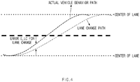
- FIG. 4 is a view for describing an operation of determining whether a vehicle leans, in one form of the present disclosure.
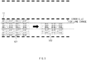
- FIG. 5 is a view illustrating an example of reducing an area corresponding to lane return according to determination of leaning of a vehicle, according to another form of the present disclosure.
- the lane change controlling apparatus 100 may determine that a lane change behavior is fast, to reduce an area corresponding to original lane return LCA Zone for returning to an original lane, thereby inhibiting or preventing lane departure while returning, when a lateral location error for a lane change path is not less than an arbitrary value TBD (30 cm) in a lane change direction and the tilt occurs continuously during a specific time in a state where there is no intervention of a user (a driver) (when MDPS column torque is not greater than a reference value).
- TBD arbitrary value
- the lane change controlling apparatus 100 may calculate an error E_LC for the lane change to reduce an area corresponding to original lane return 501 by the error E_LC for the lane change, when a vehicle leans; it is understood that the final area corresponding to original lane return 502 is reduced.
- FIG. 6 is a flowchart for describing a method of generating an area corresponding to lane return, in another form of the present disclosure.
- the lane change controlling apparatus 100 of FIG. 1 performs the process of FIG. 6 .
- an operation described as being performed by a device is controlled by the processor 140 of the device 100.
- the lane change controlling apparatus 100 may generate a lane change path for the lane change, when a turn signal for the lane change is turned on by a user.
- the lane change controlling apparatus 100 may generate an error for the lane change; and in operation S103, the lane change controlling apparatus 100 may determine whether the tilt in a lane change direction occurs.
- the lane change controlling apparatus 100 may compare a lane change path with an actual vehicle behavior path, may generate the error E_LC for the lane change that is a lateral difference value between the lane change path and the actual vehicle behavior path, and may determine that the tilt in the lane change direction occurs, when the error for the lane change is not less than a predetermined reference value (e.g., 30 cm).
- a predetermined reference value e.g. 30 cm
- the lane change controlling apparatus 100 may generate the area corresponding to original lane return based on the left and right lanes of the current driving lane and the overall length of the vehicle, when the tilt in the lane change direction does not occur, that is, when the error for the lane change is less than the predetermined reference value.
- the area corresponding to original lane return may be generated by calculating the lateral distance DisToTire between the vehicle 10 and the lane; as described in Equation 3, the lateral distance DisToTire between the vehicle 10 and the lane is a lateral distance between the left-side tire of the vehicle 10 and the lane.
- the lane change controlling apparatus 100 may generate the entire lateral area (from left-side lane to right-side lane) of a lane, as the area corresponding to original lane return.
- the lane change controlling apparatus 100 may subtracts the error for the lane change from the lateral distance DisToTire between the vehicle 10 and the lane to reduce the lateral distance DisToTire between the vehicle 10 and the lane, when the tilt in the lane change direction occurs, that is, when the error for the lane change is not less than the predetermined reference value As illustrated in '502' of FIG. 5 , it is understood that the lateral distance DisToTire between the vehicle 10 and the lane is reduced as compared with '501'.
- the lane change controlling apparatus 100 may generate and store the area corresponding to original lane return according to the tilt in the lane change direction, when the lane change path is generated while the vehicle is driving; the lane change controlling apparatus 100 may use the area corresponding to original lane return, when the lane change procedure is interrupted or when determining whether to return to an original lane, in FIG. 7 later.
- the lane change controlling apparatus 100 may reduce the area corresponding to original lane return when the tilt in the lane change direction occurs, thereby inhibiting or preventing lane departure, or the like when the vehicle returns to an original lane.
- FIG. 7 is a flowchart for describing a method for controlling lane change of a vehicle, according to an exemplary form of the present disclosure.
- the lane change controlling apparatus 100 of FIG. 1 performs the process of FIG. 7 .
- an operation described as being performed by a device is controlled by the processor 140 of the device 100.
- the lane change controlling apparatus 100 may generate a lane change path for the lane change, when a turn signal for the lane change is turned on by a user.
- the lane change controlling apparatus 100 may determine whether a condition that a lane change procedure is interrupted occurs, while a vehicle is driving along on a lane change path.
- the condition that the lane change procedure is interrupted may include 1) when a dangerous situation is sensed, 2) when hand-off is sensed, 3) in the case of cancellation (the case where a user turns off a turn signal) by a user, 4) when a lane change operation is not started within a predetermined time (e.g., 5 seconds) after the user manipulates a turn signal, 5) when a lane change function is turned off or overridden by the user, 6) when the limit of a system is reached (the case where a lane is not recognized, or the like), 7) when an operation of approaching a lane and lateral movement for completing the lane change operation are not continuous during the lane change procedure, or the like.
- the lane change controlling apparatus 100 may determine whether the condition corresponds to an event to return to an original lane, when the condition that the lane change procedure is interrupted occurs.
- the event to return to an original lane may correspond to 1) the case where the dangerous situation is sensed, 2) the case where the hand-off is sensed, 3) the case of the cancellation (the case where a user turns off a turn signal) by a user, or 4) the case where the lane change operation is not started within a predetermined time (e.g., 5 seconds) after the user manipulates the turn signal.
- the lane change controlling apparatus 100 may determine whether the vehicle is placed within an area corresponding to original lane return, when the case corresponds to the event to return to an original lane. At this time, the lane change controlling apparatus 100 may recognize a lane from camera image information or information obtained by a sensor such as radar, LiDAR, or the like and may determine whether the vehicle is placed within the area corresponding to original lane return, by using GPS information or the like received from the GPS receiver 300.
- a sensor such as radar, LiDAR, or the like
- the lane change controlling apparatus 100 may determine whether it is not possible to return to an original lane, when the vehicle is not placed within the area corresponding to original lane return, or when the probability that the vehicle will cross the lane is great based on the behavior of the vehicle; in operation S205, the lane change controlling apparatus 100 may sense whether the current situation is a dangerous situation, during the lane change; in operation S206 may perform a dangerous situation notification, when the current situation is the dangerous situation. At this time, the lane change controlling apparatus 100 may determine the dangerous situation during the lane change in consideration of whether the vehicle collides with a nearby vehicle; the lane change controlling apparatus 100 may perform the visual, auditory, and tactile dangerous situation notification.
- the lane change controlling apparatus 100 may maintain a lane change path to perform lane change control and may determine whether the lane change procedure is completed.
- the lane change controlling apparatus 100 performs lane keeping control on the changed current lane, when the lane change procedure is completed.
- the lane change controlling apparatus 100 determines that it is possible to return to an original lane, generates a path for returning to an original lane, and performs a notification that the lane change procedure is interrupted, when the vehicle is placed within the area corresponding to original lane return in operation S204.
- the lane change controlling apparatus 100 senses whether the current situation is the dangerous situation, when returning to the original lane; in operation S211, the lane change controlling apparatus 100 performs the dangerous situation notification, in the case of the dangerous situation.
- the lane change controlling apparatus 100 may control the vehicle to return to the original lane depending on the generated path for returning to an original lane and may determine whether original lane return control is terminated. In operation S208, the lane change controlling apparatus 100 performs lane keeping control on the changed current lane (original lane), when the original lane return control is completed.
- the lane change controlling apparatus 100 determines whether a lane is not recognized, when the event to return to an original lane does not occur in operation S203, that is, 5) when a lane change function is turned off or overridden by a user, 6) when the limit of a system is reached (the case where a lane is not recognized, or the like), 7) when an operation of approaching a lane and lateral movement for completing the lane change operation are not continuous during the lane change procedure, among the conditions that a lane change procedure is interrupted.
- the lane change controlling apparatus 100 In operation S214, the lane change controlling apparatus 100 generates a lane recognition-based lane keeping path and performs a notification that the lane change is interrupted, when the lane is recognized. That is, since it is possible to recognize a lane, 5) when a lane change function is turned off or overridden by a user, and 7) when an operation of approaching a lane and lateral movement for completing the lane change operation are not continuous during the lane change procedure, among the conditions that a lane change procedure is interrupted, the lane change controlling apparatus 100 generates a lane keeping path, allows the current lane to be maintained, and interrupts the lane change.
- the lane change controlling apparatus 100 performs a notification that the lane change procedure is interrupted, without generating a path.
- the lane change controlling apparatus 100 may transfer the control of the lateral movement to the user and may allow the user to directly perform the control of the lateral movement.
- the notification that the lane change procedure is interrupted may be performed with visual, auditory, or tactile sense.
- the present disclosure may determine the condition that a lane change procedure is interrupted and an event to return to an original lane during the lane change procedure and may perform control such as lane change keeping, the interruption of the lane change procedure, the control of original lane return, current lane keeping, or the like, thereby providing a user with the minimum sense of difference and improving the usability of the lane change assist function.
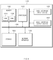
- FIG. 8 illustrates a computing system according to an exemplary form of the present disclosure.
- a computing system 1000 may include at least one processor 1100, a memory 1300, a user interface input device 1400, a user interface output device 1500, a storage 1600, and a network interface 1700, which are connected with each other via a bus 1200.
- the processor 1100 may be a central processing unit (CPU) or a semiconductor device that processes instructions stored in the memory 1300 and/or the storage 1600.
- CPU central processing unit
- Each of the memory 1300 and the storage 1600 may include various types of volatile or nonvolatile storage media.
- the memory 1300 may include a read only memory (ROM) and a random access memory (RAM).
- the operations of the methods or algorithms described in connection with the forms disclosed in the specification may be directly implemented with a hardware module, a software module, or a combination of the hardware module and the software module, which is executed by the processor 1100.
- the software module may reside on a storage medium (i.e., the memory 1300 and/or the storage 1600) such as a RAM, a flash memory, a ROM, an erasable and programmable ROM (EPROM), an electrically EPROM (EEPROM), a register, a hard disc, a removable disc, or a compact disc-ROM (CD-ROM).
- the storage medium may be coupled to the processor 1100.
- the processor 1100 may read out information from the storage medium and may write information in the storage medium.
- the storage medium may be integrated with the processor 1100.
- the processor and storage medium may be implemented with an application specific integrated circuit (ASIC).
- ASIC application specific integrated circuit
- the ASIC may reside in a user terminal.
- the processor and storage medium may be implemented with separate components in the user terminal.
- the present disclosure may perform lane change control and lane change cancellation control for minimizing the sense of difference of a user, thereby improving the usability of the lane change assist function.
Abstract
Description
- This application claims priority to and the benefit of Korean Patent Application No.
10-2018-0122831, filed on October 15, 2018 US Application No. 62/655,831, filed on April 11, 2018 - The present disclosure relates to an apparatus for controlling a lane change of a vehicle, a system having the same and method thereof.
- The statements in this section merely provide background information related to the present disclosure and may not constitute prior art.
- Nowadays, with the rapid development of the IT technology, the interest in the intelligent automobile converged with a vision system is increasing. In particular, the advanced safety automobile technology, which reduces the risk of traffic accidents and assists safety driving, such as a lane departure warning system, a lane keeping assist system, a collision warning system, and a lane change controlling system is based on the intelligent automobile technology, and a great deal of manpower and resources are invested in various research and technology development. In particular, a lane change controlling system capable of automatically changing a lane on which a vehicle is driving may automatically control the vehicle to perform the lane change, when a driver manipulates a turn signal to change the lane.
- The lane change controlling system may determine whether the speed, location, or the like of a nearby vehicle is suitable to perform the lane change, may set a control path for the lane change, and may control steering torque depending on the control path, and thus may perform the lane change.
- However, we have discovered that when a lane change procedure needs to be interrupted before a lane change operation, a conventional lane change controlling system may interrupt a lane change procedure, however, this lane change control system does not take into account the situation where the lane change procedure needs to be interrupted after the lane change operation is started.
- An aspect of the present disclosure provides an apparatus for controlling a lane change of a vehicle, a system having the same and method thereof that perform lane change control and lane change cancellation control for minimizing the sense of difference of a user, thereby improving the usability of the lane change assist function.
- The technical problems to be solved by the present inventive concept are not limited to the aforementioned problems, and any other technical problems not mentioned herein will be clearly understood from the following description by those skilled in the art to which the present disclosure pertains.
- According to an aspect of the present disclosure, an apparatus for controlling lane change of a vehicle may include: a processor configured to determine whether a condition of interrupting a lane change procedure occurs, during controlling the lane change, and configured to determined, when the condition of interrupting the lane change procedure occurs, whether to interrupt the lane change procedure or whether to return the vehicle to an original lane to control the vehicle depending on the result; and a storage configured to store the outputs determined by the processor.
- According to an exemplary form, the processor may be configured to calculate a lane change path, when receiving a lane change request and to determine whether the vehicle leans toward a target lane in a lane change direction.
- According to another form, the processor may be configured to calculate a difference value between the lane change path and an actual vehicle behavior path based on an error in the lane change.
- According to another exemplary form, the processor may be configured to determine that the vehicle does not lean, when the error for the lane change is less than a predetermined reference value and to generate a returning area to return the vehicle to the original lane based on a distance from a center of the vehicle to a lane mark of a current lane on which the vehicle is travelling, and a value corresponding to a half of an overall width of the vehicle.
- According to another form, the processor may be configured to determine that the vehicle leans toward the target lane, when the error in the lane change is equal to or greater than the predetermined reference value.
- According to other form, the processor may be configured to reduce the calculated returning area when it is determined that the vehicle leans toward the target lane.
- According to another form, the processor may be configured to reduce the calculated returning area corresponding to the error in the lane change.
- According to another exemplary form, the processor may be configured to determine whether the condition that the lane change procedure is interrupted occurs.
- In one form, the processor may be configured to determine that the condition that the lane change procedure is interrupted occurs, when at least one or more of a case that a dangerous situation is sensed, a case that hand-off state of a user of the vehicle is sensed, a case that a lane change procedure cancellation request is generated by a user, a case that a lane change operation is not started within a predetermined time after the user requests a lane change, a case that a lane change function is turned off or overridden by the user, a case that an operation of approaching a lane and lateral movement for completing the lane change operation are not continuous while a lane is not recognized or during the lane change procedure are satisfied.
- In another form, the processor may be configured to determine whether an event to return the vehicle to the original lane occurs, when the condition that the lane change procedure is interrupted occurs.
- According to another form, the processor may be configured to determine that the event to return the vehicle to the original lane occurs, when at least one or more of a case that a lane change function is turned off or overridden by a user, a case that an operation of approaching a lane and lateral movement for completing a lane change operation are not continuous while a lane is not recognized or during the lane change procedure are satisfied.
- According to other form, the processor may be configured to determine whether the vehicle is placed within a returning area corresponding to an area to return the vehicle to the original lane return, when the event to return to the original lane occurs.
- According to another form, the processor may be configured to calculate a path for returning to the original lane and to provide a notification that the lane change procedure is interrupted, when the vehicle is placed within the returning area for the original lane return.
- According to another form, the processor may be configured to keep a lane change path continuously, when the vehicle is not placed within the returning area corresponding to the original lane return.
- According to another form, the processor may be configured to determine whether a lane is not recognized, when the event to return to the original lane does not occur.
- According to another form, the processor may be configured to generate a path for keeping a current lane and to provide a notification that the lane change procedure is interrupted, when the lane is recognized.
- According to another form, the processor may be configured to provide a notification that the lane change procedure is interrupted, without generating a lane change path, when the lane is not recognized.
- According to other form, the processor may be configured to sense a dangerous situation, when a relative longitudinal distance of a nearby vehicle is less than a predetermined safe reference with respect to the vehicle and to determine a hand-off state of the user when a steering torque and a steering torque change rate are equal to or less than predetermined corresponding reference values, respectively.
- In other form, a vehicle system may include a lane change controlling apparatus configured to: determine whether a condition of interrupting a lane change procedure occurs, during controlling the lane change, and determined whether to interrupt the lane change procedure or whether to return the vehicle to an original lane to control the vehicle, when the condition of interrupting the lane change procedure occurs. The vehicle system further includes a warning device outputting a notification when the lane change procedure is interrupted.
- According to another aspect of the present disclosure, a method for controlling lane change of a vehicle may include: determining, by a processor, whether a condition of interrupting a lane change procedure occurs, during controlling the lane change; when the condition of interrupting the lane change procedure occurs, determining, by the processor, whether to interrupt the lane change procedure or whether to return the vehicle to an original lane to control the vehicle; outputting, by a warning device, a notification when the lane change procedure is interrupted, and controlling the vehicle depending on the determination result.
- Further areas of applicability will become apparent from the description provided herein. It should be understood that the description and specific examples are intended for purposes of illustration only and are not intended to limit the scope of the present disclosure.
- In order that the disclosure may be well understood, there will now be described various forms thereof, given by way of example, reference being made to the accompanying drawings, in which:
-
FIG. 1 is a block diagram of a configuration of a vehicle system including an apparatus for controlling a lane change of a vehicle; -
FIG. 2 is a view for describing an operation of determining whether a lane change operation of a vehicle is started; -
FIG. 3 is a view for describing an exemplary operation at a point in time when a lane change operation of a vehicle is started, and at a point in time when a lane change operation of a vehicle ends; -
FIG. 4 is a view for describing an operation of determining whether a vehicle leans; -
FIG. 5 is a view illustrating an example of reducing an area corresponding to lane return according to determination of leaning of a vehicle; -
FIG. 6 is a flowchart for describing a method of generating an area corresponding to lane return; -
FIG. 7 is a flowchart for describing a method for controlling lane change of a vehicle; and -
FIG. 8 a block diagram illustrating a computing system. - The drawings described herein are for illustration purposes only and are not intended to limit the scope of the present disclosure in any way.
- The following description is merely exemplary in nature and is not intended to limit the present disclosure, application, or uses. It should be understood that throughout the drawings, corresponding reference numerals indicate like or corresponding parts and features.
- In addition, a detailed description of well-known features or functions will be ruled out in order not to unnecessarily obscure the gist of the present disclosure.
- In describing elements of exemplary forms of the present disclosure, the terms first, second, A, B, (a), (b), and the like may be used herein. These terms are only used to distinguish one element from another element, but do not limit the corresponding elements irrespective of the order or priority of the corresponding elements. Furthermore, unless otherwise defined, all terms including technical and scientific terms used herein are to be interpreted as is customary in the art to which this present disclosure belongs. It will be understood that terms used herein should be interpreted as having a meaning that is consistent with their meaning in the context of the present disclosure and the relevant art and will not be interpreted in an idealized or overly formal sense unless expressly so defined herein.
- In the present disclosure, a lane change assist function may be performed through a procedure of 1) lighting a turn signal by a driver, 2) lateral movement to the lane boundary in the direction of the movement lane, 3) a lane change operation (lane crossing), 4) a lane keeping function, and 5) automatically turning off a turn signal (by a system) .
- The lane change operation is defined as an operation in which the front tire of a vehicle starts to touch the inside of the lane close to the movement lane and then the vehicle completely crosses the lane. Furthermore, the lane change procedure needs to be interrupted, when a condition that the lane change procedure is interrupted occurs before a lane change operation is started; the present disclosure discloses a function of determining the condition that the lane change procedure is interrupted and then interrupting the lane change procedure, providing a notification that the lane change procedure is interrupted, determining original lane return control, performing original lane return control, and the like.
- Below, various forms of the present disclosure will be described in detail with reference to
FIGS. 1 to 8 . -
FIG. 1 is a block diagram of a vehicle system including an apparatus for controlling a lane change of a vehicle, according to an exemplary form of the present disclosure. - The vehicle system according to an form of the present disclosure may include: a lane change controlling apparatus 100, a
sensing module 200, a Global Positioning System (GPS)receiver 300, anavigation device 400, aninput device 500, asteering device 600, an acceleration/deceleration device 700, and awarning device 800. The vehicle system ofFIG. 1 may be mounted in a vehicle. - The lane change controlling apparatus 100 may determine whether it is possible to change a lane of a vehicle, whether to interrupt a lane change procedure, whether to return the vehicle to an original lane after the lane change is cancelled, whether to provide a notification that a lane change procedure is interrupted, or the like, based on GPS information received from the
GPS receiver 300, map information received from thenavigation device 400, and the peripheral sensing information sensed by thesensing module 200. - The lane change controlling apparatus 100 may be electrically connected to the
sensing module 200, theGPS receiver 300, thenavigation device 400, theinput device 500, thesteering device 600, the acceleration/deceleration device 700, thewarning device 800, and the like, may control thesensing module 200, theGPS receiver 300, thenavigation device 400, theinput device 500, thesteering device 600, the acceleration/deceleration device 700, and thewarning device 800, and may perform various data processing and calculation. - To this end, the lane change controlling apparatus 100 of a vehicle may include a
communication device 110,storage 120, adisplay device 130, and aprocessor 140. - The
communication device 110 may be a hardware device implemented with various electronic circuits for transmitting and receiving signals via a wireless or wired connection; in the present disclosure, thecommunication device 110 may communicate with devices in a vehicle over CAN communication, LIN communication, or the like and may communicate with devices outside the vehicle over wireless communication. - The
storage 120 may store information received from thesensing module 200, theGPS receiver 300, thenavigation device 400, and the like, and the determination result of whether it is possible to change a lane of a vehicle, whether to interrupt a lane change procedure, whether to return to an original lane after the lane change is cancelled, whether to provide a notification that a lane change procedure is interrupted, or the like, which is determined by theprocessor 140, and an area corresponding to original lane return. Thestorage 120 may include at least one type of a storage medium among a flash memory type of a memory, a hard disk type of a memory, a micro type of a memory, and a card type (e.g., a Secure Digital (SD) card or an eXtream Digital (XD) Card) of a memory, a Random Access Memory (RAM) type of a memory, a Static RAM (SRAM) type of a memory, a Read-Only Memory (ROM) type of a memory, a Programmable ROM (PROM) type of a memory, an Electrically Erasable PROM (EEPROM) type of a memory, an Magnetic RAM (MRAM) type of a memory, a magnetic disk type of a memory, and an optical disc type of a memory. - The
display device 130 may display a determination result of whether it is possible to change a lane of a vehicle, whether to interrupt a lane change procedure, whether to return to an original lane after the lane change is cancelled, or the like and a notification of a dangerous situation, a lane change path, a path for returning to an original lane, or the like. Thedisplay device 130 may be implemented with a Head Up Display (HUD), a cluster, an Audio Video Navigation (AVN), or the like. In addition, thedisplay device 130 may directly receive a color input from a user through a User Setting Menu (USM) menu of a cluster. Furthermore, thedisplay device 130 may include at least one of a Liquid Crystal Display (LCD), a Thin Film Transistor-LCD (TFT LCD), a Light Emitting Diode (LED) display, an Organic LED (OLED) display, an Active Matrix OLED (AMOLED) display, a flexible display, a bended display, and a 3D display. Some of the displays may be implemented with a transparent display that is transparent or optically transparent to view the outside. Moreover, thedisplay device 130 may be provided as a touchscreen including a touch panel and may be used as an input device in addition to an output device. - The
processor 140 may be electrically connected to thecommunication device 110, thestorage 120, and thedisplay device 130, may electrically control each of the components, may be an electrical circuit that executes the instructions of the software, and may perform various data processing and calculation described below. For example, theprocessor 140 may be an electronic control unit (ECU) or a sub-controller, which is mounted in the vehicle. - The
processor 140 may determine whether it is possible to change a lane of a vehicle, whether to interrupt a lane change procedure, whether to return to an original lane after the lane change is cancelled, whether to provide a notification that a lane change procedure is interrupted, or the like based on surrounding situation information; and the surrounding situation information may include at least one or more of GPS information received from theGPS receiver 300, map information received from thenavigation device 400, and surrounding information sensed by thesensing module 200. - The
processor 140 may generate a lane change path and/or a path for returning to an original lane that is based on GPS reception information or thenavigation device 400. - The
processor 140 may generate a lane change path and may determine whether a vehicle leans toward a target lane in a lane change direction, when receiving a lane change request (e.g., when a turn signal is turned on by a user). - The
processor 140 may calculate a difference value between the lane change path and an actual vehicle behavior path based on an error in the lane change; theprocessor 140 may determine that a vehicle does not lean toward the target lane, when the error for the lane change is less than a predetermined reference value; and theprocessor 140 may generate a returning area corresponding to an area to return the vehicle to the original lane by using a distance from the center of the vehicle to a lane mark of a current lane on which the vehicle is travelling, and a value that is a half of the overall width of the vehicle. At this time, the returning area may be an area that is referenced when a vehicle returns to the original lane (e.g., the previous lane on which the vehicle previously travelled before the lane change to the target lane), may correspond to a determination area for determining whether the vehicle returns to the original lane, and may be changed depending on the leaning of the vehicle. - The
processor 140 may determine that a vehicle leans toward the target lane, when the error in the lane change is equal to or greater than a predetermined reference value; theprocessor 140 may reduce and generate the returning area corresponding to original lane return, when a vehicle leans. At this time, theprocessor 140 may reduce the returning area corresponding to original lane return by the error in the lane change and may generate the reduced area corresponding to original lane return. - The
processor 140 may determine whether a condition (situation) that the lane change procedure is interrupted occurs, before the lane change operation is started; theprocessor 140 may interrupt the lane change procedure, when the condition that the lane change procedure is interrupted occurs. - The condition that the lane change procedure is interrupted may include 1) when a dangerous situation is sensed, 2) when hand-off is sensed, 3) in the case of cancellation (the case where a user turns off a turn signal) by a user, 4) when a lane change operation is not started within a predetermined time (e.g., 5 seconds) after the user requests a lane change (e.g., after the user manipulates a turn signal), 5) when a lane change function is turned off or overridden by the user, 6) when the limit of a system is reached (the case where a lane is not recognized, or the like), 7) when an operation of approaching a lane and lateral movement for completing the lane change operation are not continuous during the lane change procedure, or the like.
- For the purpose of 1) determining whether the dangerous situation is sensed, the
processor 140 may determine whether a relative longitudinal distance (with respect to the vehicle) of a nearby vehicle is less than a predetermined safe distance Scritical. At this time, the safe distance is represented by Equation 1.
- Vrear may indicate the lower value among the actual speed of an approaching vehicle or 130 km/h; VACSF may indicate the actual speed of an ACSF vehicle; 'a' may indicate the deceleration of the approaching vehicle; tG may indicate a value obtained by subtracting the speed reference of the ACSF vehicle from a margin interval of the vehicles after the deceleration of the approaching vehicle; 'tB' may indicate a time period before the approaching vehicle starts to decelerate after the lane change operation is started.
- The
processor 140 may determine that the dangerous situation is sensed, when the relative longitudinal distance (with respect to the vehicle) of a nearby vehicle is less than the predetermined safe distance Scritical. - Moreover, for the purpose of 2) determining the hand-off of a driver, the
processor 140 may determine that the hand-off is sensed, when the absolute value of each of torque and a torque change rate is not greater than a reference value.
- |Tq| may indicate the absolute value of the steering torque; |Tq_Delta| may indicate the absolute value of the steering torque change rate; Tq_Handsoff_Ref may indicate an arbitrary reference value.
- For the purpose of 3) determining whether the user turns off a turn signal, the
processor 140 may determine whether the switch of the turn signal is turned off. That is, in a state where the switch of the turn signal is turned on to request the lane change, theprocessor 140 may interrupt the lane change procedure, when the user turns off the switch of the turn signal again. - In addition, for the purpose of 4) determining whether the lane change operation is delayed, the
processor 140 may determine that the lane change operation is delayed and then may interrupt the lane change procedure, when the lane change operation is not started within a predetermined time (e.g., 5 seconds) after the user manipulates the turn signal. - For the purpose of 5) determining whether the lane change function is turned off or overridden by the user, the
processor 140 may determine whether a lane change function button is turned off by the user or whether the absolute value of the torque is not less than an arbitrary reference value, to determine whether the lane change function is overridden. Theprocessor 140 may interrupt the lane change procedure, when the lane change function is turned off or overridden by the user. - For the purpose of 6) determining whether the limit of a system is reached, the
processor 140 may determine a situation that a lane is not recognized, or the like. The situation that a lane is not recognized is the case where the reliability of both lanes being the output of a camera is low; in this case, theprocessor 140 may interrupt the lane change procedure. - For the purpose of 7) determining whether a lane change is abnormal, the
processor 140 may determine that the current location in a lane is maintained during a specific time, during the lane change. That is, when the operation of approaching a lane and the lateral movement for completing the lane change operation are not continuous during the lane change procedure, theprocessor 140 may determine that the lateral movement of the lane change is abnormal due to disturbance (transverse gradient, or the like), when a lateral distance DisToTire to a lane in the lane changing direction may be similarly maintained to be equal to or greater than a specific time TLatHoldLC TBD and a lateral error increases as compared with a lane change path. As such, theprocessor 140 may interrupt the lane change procedure, when it is determined that the lane change is abnormal. - The
processor 140 may determine the current location of the vehicle or whether the lane change operation is started and then may determine whether to return to an original lane, 1) when the dangerous situation is sensed, 2) when the hand-off is sensed, 3) in the case of the cancellation (the case where a user turns off a turn signal) by a user, or 4) when the lane change operation is not started within a predetermined time (e.g., 5 seconds) after the user manipulates the turn signal. - The
processor 140 may immediately transfer the control of the lateral movement to the user regardless of the current location of the vehicle or whether the lane change operation is started, may not generate a path or may generate a lane-keeping control path, and may respond to the situations, 5) when the lane change function is turned off or overridden by the user, 6) when the limit of a system is reached (the case where a lane is not recognized, or the like), or 7) when the operation of approaching a lane and the lateral movement for completing the lane change operation are not continuous during the lane change procedure. - That is, the
processor 140 may determine whether the steering of the user intervenes, when a situation corresponds to Nos. 5, 6, or 7; theprocessor 140 may not generate a path, when the steering of the user intervenes; theprocessor 140 may provide a notification that a lane-keeping path is generated and the lane change is interrupted, when the steering of the user does not intervene. - Furthermore, the
processor 140 may determine whether the vehicle is present within the area corresponding to original lane return, 1) when a dangerous situation is sensed, 2) when the hand-off is sensed, 3) in the case of the cancellation (the case where a user turns off a turn signal) by a driver, or 4) when the lane change operation is not started within 5 seconds after the driver manipulates the turn signal; theprocessor 140 may generate a path for returning to an original lane and may provide a notification that the lane change is interrupted, when the vehicle is present within the area corresponding to original lane return. - Also, since the probability that the vehicle will cross the lane is great based on the behavior of the vehicle, the
processor 140 may maintain the lane change procedure, when the vehicle is not present within the returning area corresponding to original lane return. In addition, theprocessor 140 may maintain the lane change procedure, when the vehicle is not present within the returning area corresponding to original lane return; theprocessor 140 may notify the user of the dangerous situation, when the dangerous situation is sensed. - As such, the lane change controlling apparatus 100 according to an exemplary form of the present disclosure may change a lane, may interrupt the lane change procedure, may keep a lane, may not generate a path, may change a path, and may provide a notification that the lane change procedure is interrupted, when a condition that the lane change procedure is interrupted occurs, thereby reducing or minimizing the sense of difference such that the user fully recognizes the situations.
- Furthermore, the present disclosure may change a returning area corresponding to original lane return that is the determination area for determining the path change, depending on the leaning of the vehicle, thereby inhibiting or preventing lane departure, or the like when the vehicle returns to a lane.
- The
sensing module 200 may be configured to obtain information about external objects (e.g., nearby vehicles, pedestrians, motor cycles, bicycles, median strips, the number of lanes of driving roads) that are driving in the same lane, which the vehicle is driving, and a neighboring lane to sense the surrounding situation. The information about the external objects may include the location, speed, type, direction of movement, or the like of each of the external objects. To this end, thesensing module 200 may include at least one or more of a camera, radar, LiDAR, an ultrasonic sensor, an acceleration sensor, a yaw rate sensor, a torque measurement sensor and/or a wheel speed sensor. Moreover, at least one or more sensors may be mounted on the front, rear, left and right sides of the vehicle. - The
GPS receiver 300 receives a GPS signal from a GPS satellite and transmits the GPS signal to the lane change controlling apparatus 100. As such, the lane change controlling apparatus 100 may determine the current location (e.g., whether the vehicle is present within an area for returning to an original lane, or the like) of the vehicle by using the GPS signal. - The
navigation device 400 provides the lane change controlling apparatus 100 with map information according to the location and destination of the vehicle. At this time, the lane change controlling apparatus 100 may operate in conjunction with thenavigation device 400 to generate lane change path information and information about a path for returning to an original lane; the lane change controlling apparatus 100 may receive and use the lane change path information and information about the path for returning to an original lane from thenavigation device 400. - The
input device 500 may be configured to receive a lane change command from a user; the present disclosure may include a direction indication lever, a switch, a button, or the like, which is capable of receiving a user input, for the lane change. - The
steering device 600 may be configured to control the steering angle of the vehicle and may include a steering wheel, an actuator operating in conjunction with the steering wheel, and a controller for controlling the actuator. - The acceleration/
deceleration device 700 may be configured to control the speed of the vehicle and may include a throttle, a brake, an actuator operating in conjunction with the throttle and the brake, and a controller that controls the actuator. - The
warning device 800 may perform a warning, such as a lane change notification, a notification that the lane change procedure is interrupted, a notification of returning to an original lane, a dangerous situation notification, or the like. Thewarning device 800 may include a configuration for performing the visual, auditory, and tactile warning. - As such, the present disclosure may perform a lane change control, when receiving a lane change request from the user; the present disclosure may determine a condition that a lane change procedure is interrupted, a condition of returning to an original lane, or the like to rapidly perform the lane change, the lane change cancellation, and the original lane return, depending on situations, thereby enhancing the user's convenience and improving the usability of a lane change assist function.
-
FIG. 2 is a view for describing an operation of determining whether a lane change operation of a vehicle is started, according to an exemplary form of the present disclosure.FIG. 3 is a view for describing an exemplary operation at a point in time when a lane change operation of a vehicle is started, and at a point in time when a lane change operation of a vehicle ends, according to another form of the present disclosure. - Referring to
FIG. 2 , the lane change controlling apparatus 100 may determine whether the lane change operation is started, by using a lateral distance DisToTire between avehicle 10 and a lane, when thevehicle 10 crosses the left lane to perform the lane change. That is, the lateral distance DisToTire between thevehicle 10 and the lane may be a lateral distance between the left-side tire of thevehicle 10 and the lane; and the lateral distance DisToTire between thevehicle 10 and the lane may be represented by the following Equation 3.
- D1 is a distance from the center of the vehicle to a lane, and D2 indicates the vehicle's overall width/2.
- At this time, D1 may be obtained through the
sensing module 200, and D2 may be stored in advance. It is possible to determine that a point in time when the sign of the lateral distance DisToTire between thevehicle 10 and the lane is inverted is the start of the changing operation. - Referring to '301' of
FIG. 3 , all the tires of thevehicle 10 are placed within a returning area corresponding tooriginal lane return 303. However, the lane change controlling apparatus 100 determines that the lane change operation is started, based on a state where thevehicle 10 is adjacent to a return reference line 11 (lane) and the sign of the lateral distance DisToTire between thevehicle 10 and the lane is inverted. - Referring to '302' of
FIG. 3 , an example in which the lane change operation is terminated is illustrated as the case where thevehicle 10 crosses the return reference line 11 (lane) and all the tires of thevehicle 10 are out of the area corresponding tooriginal lane return 303. -
FIG. 4 is a view for describing an operation of determining whether a vehicle leans, in one form of the present disclosure.FIG. 5 is a view illustrating an example of reducing an area corresponding to lane return according to determination of leaning of a vehicle, according to another form of the present disclosure. - Referring to
FIG. 4 , the lane change controlling apparatus 100 may determine that a lane change behavior is fast, to reduce an area corresponding to original lane return LCA Zone for returning to an original lane, thereby inhibiting or preventing lane departure while returning, when a lateral location error for a lane change path is not less than an arbitrary value TBD (30 cm) in a lane change direction and the tilt occurs continuously during a specific time in a state where there is no intervention of a user (a driver) (when MDPS column torque is not greater than a reference value). - Referring to
FIG. 5 , the lane change controlling apparatus 100 may calculate an error E_LC for the lane change to reduce an area corresponding tooriginal lane return 501 by the error E_LC for the lane change, when a vehicle leans; it is understood that the final area corresponding tooriginal lane return 502 is reduced. - Hereinafter, in one form of the present disclosure, a method of generating an area corresponding to lane return will be described with reference to
FIG. 6. FIG. 6 is a flowchart for describing a method of generating an area corresponding to lane return, in another form of the present disclosure. - Hereinafter, it is assumed that the lane change controlling apparatus 100 of
FIG. 1 performs the process ofFIG. 6 . In addition, in a description ofFIG. 6 , it may be understood that an operation described as being performed by a device is controlled by theprocessor 140 of the device 100. - Referring to
FIG. 6 , in operation S101, the lane change controlling apparatus 100 may generate a lane change path for the lane change, when a turn signal for the lane change is turned on by a user. - In operation S102, the lane change controlling apparatus 100 may generate an error for the lane change; and in operation S103, the lane change controlling apparatus 100 may determine whether the tilt in a lane change direction occurs. At this time, as illustrated in
FIG. 4 , the lane change controlling apparatus 100 may compare a lane change path with an actual vehicle behavior path, may generate the error E_LC for the lane change that is a lateral difference value between the lane change path and the actual vehicle behavior path, and may determine that the tilt in the lane change direction occurs, when the error for the lane change is not less than a predetermined reference value (e.g., 30 cm). - In operation S104, the lane change controlling apparatus 100 may generate the area corresponding to original lane return based on the left and right lanes of the current driving lane and the overall length of the vehicle, when the tilt in the lane change direction does not occur, that is, when the error for the lane change is less than the predetermined reference value. As illustrated in
FIG. 2 , the area corresponding to original lane return may be generated by calculating the lateral distance DisToTire between thevehicle 10 and the lane; as described in Equation 3, the lateral distance DisToTire between thevehicle 10 and the lane is a lateral distance between the left-side tire of thevehicle 10 and the lane. As illustrated in '501' ofFIG. 5 , the lane change controlling apparatus 100 may generate the entire lateral area (from left-side lane to right-side lane) of a lane, as the area corresponding to original lane return. - In the meantime, in
operation 105, the lane change controlling apparatus 100 may subtracts the error for the lane change from the lateral distance DisToTire between thevehicle 10 and the lane to reduce the lateral distance DisToTire between thevehicle 10 and the lane, when the tilt in the lane change direction occurs, that is, when the error for the lane change is not less than the predetermined reference value As illustrated in '502' ofFIG. 5 , it is understood that the lateral distance DisToTire between thevehicle 10 and the lane is reduced as compared with '501'. - As such, the lane change controlling apparatus 100 may generate and store the area corresponding to original lane return according to the tilt in the lane change direction, when the lane change path is generated while the vehicle is driving; the lane change controlling apparatus 100 may use the area corresponding to original lane return, when the lane change procedure is interrupted or when determining whether to return to an original lane, in
FIG. 7 later. - As such, the lane change controlling apparatus 100 may reduce the area corresponding to original lane return when the tilt in the lane change direction occurs, thereby inhibiting or preventing lane departure, or the like when the vehicle returns to an original lane.
-
FIG. 7 is a flowchart for describing a method for controlling lane change of a vehicle, according to an exemplary form of the present disclosure. - Hereinafter, it is assumed that the lane change controlling apparatus 100 of
FIG. 1 performs the process ofFIG. 7 . In addition, in a description ofFIG. 7 , it may be understood that an operation described as being performed by a device is controlled by theprocessor 140 of the device 100. - In operation S201, the lane change controlling apparatus 100 may generate a lane change path for the lane change, when a turn signal for the lane change is turned on by a user.
- In operation S202, the lane change controlling apparatus 100 may determine whether a condition that a lane change procedure is interrupted occurs, while a vehicle is driving along on a lane change path. At this time, the condition that the lane change procedure is interrupted may include 1) when a dangerous situation is sensed, 2) when hand-off is sensed, 3) in the case of cancellation (the case where a user turns off a turn signal) by a user, 4) when a lane change operation is not started within a predetermined time (e.g., 5 seconds) after the user manipulates a turn signal, 5) when a lane change function is turned off or overridden by the user, 6) when the limit of a system is reached (the case where a lane is not recognized, or the like), 7) when an operation of approaching a lane and lateral movement for completing the lane change operation are not continuous during the lane change procedure, or the like.
- Next, in operation S203, the lane change controlling apparatus 100 may determine whether the condition corresponds to an event to return to an original lane, when the condition that the lane change procedure is interrupted occurs. At this time, the event to return to an original lane may correspond to 1) the case where the dangerous situation is sensed, 2) the case where the hand-off is sensed, 3) the case of the cancellation (the case where a user turns off a turn signal) by a user, or 4) the case where the lane change operation is not started within a predetermined time (e.g., 5 seconds) after the user manipulates the turn signal.
- In operation S204, the lane change controlling apparatus 100 may determine whether the vehicle is placed within an area corresponding to original lane return, when the case corresponds to the event to return to an original lane. At this time, the lane change controlling apparatus 100 may recognize a lane from camera image information or information obtained by a sensor such as radar, LiDAR, or the like and may determine whether the vehicle is placed within the area corresponding to original lane return, by using GPS information or the like received from the
GPS receiver 300. - The lane change controlling apparatus 100 may determine whether it is not possible to return to an original lane, when the vehicle is not placed within the area corresponding to original lane return, or when the probability that the vehicle will cross the lane is great based on the behavior of the vehicle; in operation S205, the lane change controlling apparatus 100 may sense whether the current situation is a dangerous situation, during the lane change; in operation S206 may perform a dangerous situation notification, when the current situation is the dangerous situation. At this time, the lane change controlling apparatus 100 may determine the dangerous situation during the lane change in consideration of whether the vehicle collides with a nearby vehicle; the lane change controlling apparatus 100 may perform the visual, auditory, and tactile dangerous situation notification.
- Afterward, in operation S207, the lane change controlling apparatus 100 may maintain a lane change path to perform lane change control and may determine whether the lane change procedure is completed. In operation S208, the lane change controlling apparatus 100 performs lane keeping control on the changed current lane, when the lane change procedure is completed.
- In operation S209, the lane change controlling apparatus 100 determines that it is possible to return to an original lane, generates a path for returning to an original lane, and performs a notification that the lane change procedure is interrupted, when the vehicle is placed within the area corresponding to original lane return in operation S204.
- Afterward, in operation S210, the lane change controlling apparatus 100 senses whether the current situation is the dangerous situation, when returning to the original lane; in operation S211, the lane change controlling apparatus 100 performs the dangerous situation notification, in the case of the dangerous situation.
- In operation S212, the lane change controlling apparatus 100 may control the vehicle to return to the original lane depending on the generated path for returning to an original lane and may determine whether original lane return control is terminated. In operation S208, the lane change controlling apparatus 100 performs lane keeping control on the changed current lane (original lane), when the original lane return control is completed.
- In the meantime, in operation S213, the lane change controlling apparatus 100 determines whether a lane is not recognized, when the event to return to an original lane does not occur in operation S203, that is, 5) when a lane change function is turned off or overridden by a user, 6) when the limit of a system is reached (the case where a lane is not recognized, or the like), 7) when an operation of approaching a lane and lateral movement for completing the lane change operation are not continuous during the lane change procedure, among the conditions that a lane change procedure is interrupted.
- In operation S214, the lane change controlling apparatus 100 generates a lane recognition-based lane keeping path and performs a notification that the lane change is interrupted, when the lane is recognized. That is, since it is possible to recognize a lane, 5) when a lane change function is turned off or overridden by a user, and 7) when an operation of approaching a lane and lateral movement for completing the lane change operation are not continuous during the lane change procedure, among the conditions that a lane change procedure is interrupted, the lane change controlling apparatus 100 generates a lane keeping path, allows the current lane to be maintained, and interrupts the lane change.
- On the other hand, since it is impossible to generate a lane keeping path when a lane is not recognized, in operation S215, the lane change controlling apparatus 100 performs a notification that the lane change procedure is interrupted, without generating a path. At this time, the lane change controlling apparatus 100 may transfer the control of the lateral movement to the user and may allow the user to directly perform the control of the lateral movement. At this time, the notification that the lane change procedure is interrupted may be performed with visual, auditory, or tactile sense.
- As such, the present disclosure may determine the condition that a lane change procedure is interrupted and an event to return to an original lane during the lane change procedure and may perform control such as lane change keeping, the interruption of the lane change procedure, the control of original lane return, current lane keeping, or the like, thereby providing a user with the minimum sense of difference and improving the usability of the lane change assist function.
-
FIG. 8 illustrates a computing system according to an exemplary form of the present disclosure. - Referring to
FIG. 8 , acomputing system 1000 may include at least oneprocessor 1100, amemory 1300, a userinterface input device 1400, a userinterface output device 1500, astorage 1600, and anetwork interface 1700, which are connected with each other via abus 1200. - The
processor 1100 may be a central processing unit (CPU) or a semiconductor device that processes instructions stored in thememory 1300 and/or thestorage 1600. Each of thememory 1300 and thestorage 1600 may include various types of volatile or nonvolatile storage media. For example, thememory 1300 may include a read only memory (ROM) and a random access memory (RAM). - Thus, the operations of the methods or algorithms described in connection with the forms disclosed in the specification may be directly implemented with a hardware module, a software module, or a combination of the hardware module and the software module, which is executed by the
processor 1100. The software module may reside on a storage medium (i.e., thememory 1300 and/or the storage 1600) such as a RAM, a flash memory, a ROM, an erasable and programmable ROM (EPROM), an electrically EPROM (EEPROM), a register, a hard disc, a removable disc, or a compact disc-ROM (CD-ROM). - The storage medium may be coupled to the
processor 1100. Theprocessor 1100 may read out information from the storage medium and may write information in the storage medium. Alternatively, the storage medium may be integrated with theprocessor 1100. The processor and storage medium may be implemented with an application specific integrated circuit (ASIC). The ASIC may reside in a user terminal. Alternatively, the processor and storage medium may be implemented with separate components in the user terminal. - Hereinabove, although the present disclosure has been described with reference to exemplary forms and the accompanying drawings, the present disclosure is not limited thereto, but may be variously modified and altered by those skilled in the art to which the present disclosure pertains without departing from the spirit and scope of the present disclosure.
- Therefore, forms of the present disclosure are not intended to limit the technical spirit of the present disclosure, but provided only for the illustrative purpose. The scope of protection of the present disclosure should be construed by the attached claims, and all equivalents thereof should be construed as being included within the scope of the present disclosure.
- The present disclosure may perform lane change control and lane change cancellation control for minimizing the sense of difference of a user, thereby improving the usability of the lane change assist function.
- Besides, a variety of effects directly or indirectly understood through this disclosure may be provided.
- Hereinabove, although the present disclosure has been described with reference to exemplary forms and the accompanying drawings, the present disclosure is not limited thereto, but may be variously modified and altered by those skilled in the art to which the present disclosure pertains without departing from the spirit and scope of the present disclosure.
Claims (15)
- An apparatus for controlling a lane change of a vehicle, the apparatus comprising:a processor configured to:determine whether a condition of interrupting a lane change procedure occurs, during controlling the lane change, andwhen the condition of interrupting the lane change procedure occurs, determine whether to interrupt the lane change procedure, or whether to return the vehicle to an original lane; anda storage configured to store outputs determined by the processor.
- The apparatus of claim 1, wherein the processor is configured to:calculate a lane change path, when receiving a lane change request; anddetermine whether the vehicle leans toward a target lane in a lane change direction.
- The apparatus of claim 2, wherein the processor is configured to:
calculate a difference value between the lane change path and an actual vehicle behavior path based on an error in the lane change. - The apparatus of claim 3, wherein the processor is configured to:determine that the vehicle does not lean, when the error in the lane change is less than a predetermined reference value; andcalculate a returning area to return the vehicle to the original lane based on a distance from a center of the vehicle to a lane mark of a current lane on which the vehicle is travelling, and a value corresponding to a half of an overall width of the vehicle.
- The apparatus of claim 4, wherein the processor is configured to:
determine that the vehicle leans toward the target lane, when the error in the lane change is equal to or greater than the predetermined reference value. - The apparatus of claim 5, wherein the processor is configured to:
reduce the calculated returning area when it is determined that the vehicle leans toward the target lane. - The apparatus of claim 6, wherein the processor is configured to:
reduce the calculated returning area corresponding to the error in the lane change. - The apparatus of claim 1, wherein the condition of interrupting the lane change procedure comprises:when a dangerous situation is sensed;,when a hand-off state of a user of the vehicle is sensed;when a request to cancel the lane change procedure is generated by the user;when a lane change operation is not started within a predetermined time after the user requests the lane change;when a lane change function is turned off or overridden by the user; andwhen an operation of approaching a lane and a lateral movement for completing the lane change operation are not continuous while a lane is not recognized or during the lane change procedure.
- The apparatus of claim 1, wherein the processor is configured to:
determine whether an event to return the vehicle to the original lane occurs, when the condition of interrupting the lane change procedure occurs. - The apparatus of claim 9, wherein the processor is configured to:
determine that the event to return the vehicle to the original lane occurs, when at least one of following cases occurs:
a case that a lane change function is turned off or overridden by a user, a case that an operation of approaching a lane and a lateral movement for completing the lane change operation are not continuous while a lane is not recognized or during the lane change procedure. - The apparatus of claim 9, wherein the processor is configured to:
determine whether the vehicle is placed within a returning area corresponding to an area to return the vehicle to the original lane, when the event to return to the original lane occurs. - The apparatus of claim 11, wherein the processor is configured to:when the vehicle is placed within the returning area,calculate a path for returning the vehicle to the original lane; andprovide a notification that the lane change procedure is interrupted.
- The apparatus of claim 12, wherein the processor is configured to:
keep a lane change path continuously, when the vehicle is not placed within the returning area. - The apparatus of claim 9, wherein the processor is configured to:
determine whether a lane is not recognized, when the event to return to the original lane does not occur. - The apparatus of claim 1, wherein the processor is configured to:sense a dangerous situation, when a relative longitudinal distance of a nearby vehicle is less than a predetermined safe reference with respect to the vehicle; anddetermine a hand-off state of a user when a steering torque or a steering torque change rate are equal to or less than predetermined corresponding reference values, respectively.
Applications Claiming Priority (2)
| Application Number | Priority Date | Filing Date | Title |
|---|---|---|---|
| US201862655831P | 2018-04-11 | 2018-04-11 | |
| KR1020180122831A KR102485354B1 (en) | 2018-04-11 | 2018-10-15 | Apparatus for controlling lane change of vehicle, system having the same and method thereof |
Publications (1)
| Publication Number | Publication Date |
|---|---|
| EP3552895A1 true EP3552895A1 (en) | 2019-10-16 |
Family
ID=64604525
Family Applications (1)
| Application Number | Title | Priority Date | Filing Date |
|---|---|---|---|
| EP18210063.6A Pending EP3552895A1 (en) | 2018-04-11 | 2018-12-04 | Apparatus for controlling lane change of vehicle |
Country Status (3)
| Country | Link |
|---|---|
| US (1) | US11077854B2 (en) |
| EP (1) | EP3552895A1 (en) |
| CN (1) | CN110371120A (en) |
Cited By (2)
| Publication number | Priority date | Publication date | Assignee | Title |
|---|---|---|---|---|
| CN112829748A (en) * | 2019-11-25 | 2021-05-25 | 现代自动车株式会社 | Lane change assist apparatus, vehicle system including the same, and method thereof |
| CN113515038A (en) * | 2021-09-07 | 2021-10-19 | 西南交通大学 | Vehicle lane changing method, device, equipment and readable storage medium |
Families Citing this family (21)
| Publication number | Priority date | Publication date | Assignee | Title |
|---|---|---|---|---|
| RU2727291C1 (en) * | 2017-04-14 | 2020-07-21 | Ниссан Мотор Ко., Лтд. | Vehicle control method and vehicle control device |
| WO2019127079A1 (en) * | 2017-12-27 | 2019-07-04 | Bayerische Motoren Werke Aktiengesellschaft | Vehicle lane change prediction |
| US11084491B2 (en) | 2018-04-11 | 2021-08-10 | Hyundai Motor Company | Apparatus and method for providing safety strategy in vehicle |
| US11351989B2 (en) | 2018-04-11 | 2022-06-07 | Hyundai Motor Company | Vehicle driving controller, system including the same, and method thereof |
| US10836394B2 (en) | 2018-04-11 | 2020-11-17 | Hyundai Motor Company | Apparatus and method for lane change control |
| US11334067B2 (en) | 2018-04-11 | 2022-05-17 | Hyundai Motor Company | Apparatus and method for providing safety strategy in vehicle |
| EP3552902A1 (en) | 2018-04-11 | 2019-10-16 | Hyundai Motor Company | Apparatus and method for providing a driving path to a vehicle |
| US11084490B2 (en) * | 2018-04-11 | 2021-08-10 | Hyundai Motor Company | Apparatus and method for controlling drive of vehicle |
| US10843710B2 (en) | 2018-04-11 | 2020-11-24 | Hyundai Motor Company | Apparatus and method for providing notification of control authority transition in vehicle |
| US11597403B2 (en) | 2018-04-11 | 2023-03-07 | Hyundai Motor Company | Apparatus for displaying driving state of vehicle, system including the same and method thereof |
| EP3552901A3 (en) | 2018-04-11 | 2020-04-29 | Hyundai Motor Company | Apparatus and method for providing safety strategy in vehicle |
| EP3569460B1 (en) | 2018-04-11 | 2024-03-20 | Hyundai Motor Company | Apparatus and method for controlling driving in vehicle |
| US11173910B2 (en) | 2018-04-11 | 2021-11-16 | Hyundai Motor Company | Lane change controller for vehicle system including the same, and method thereof |
| US11548509B2 (en) | 2018-04-11 | 2023-01-10 | Hyundai Motor Company | Apparatus and method for controlling lane change in vehicle |
| ES2889930T3 (en) | 2018-04-11 | 2022-01-14 | Hyundai Motor Co Ltd | Apparatus and method for control to enable an autonomous system in a vehicle |
| US11077854B2 (en) | 2018-04-11 | 2021-08-03 | Hyundai Motor Company | Apparatus for controlling lane change of vehicle, system having the same and method thereof |
| US11199847B2 (en) * | 2018-09-26 | 2021-12-14 | Baidu Usa Llc | Curvature corrected path sampling system for autonomous driving vehicles |
| JP7022680B2 (en) * | 2018-12-27 | 2022-02-18 | 本田技研工業株式会社 | Vehicle control device |
| DE102019213185A1 (en) * | 2019-09-02 | 2021-03-04 | Volkswagen Aktiengesellschaft | Lateral guidance of a vehicle using environmental data recorded from other vehicles |
| CN113954834A (en) * | 2020-07-15 | 2022-01-21 | 荷兰移动驱动器公司 | Lane changing planning method and vehicle-mounted device |
| CN112829750B (en) * | 2021-02-19 | 2022-10-11 | 恒大新能源汽车投资控股集团有限公司 | Vehicle lane change control method, device and system |
Citations (6)
| Publication number | Priority date | Publication date | Assignee | Title |
|---|---|---|---|---|
| EP1607264A1 (en) * | 2004-06-17 | 2005-12-21 | Robert Bosch GmbH | Lane changing assistance for a vehicle |
| JP2015138330A (en) * | 2014-01-21 | 2015-07-30 | 日産自動車株式会社 | vehicle speed control device |
| US20150360721A1 (en) * | 2014-06-17 | 2015-12-17 | Fuji Jukogyo Kabushiki Kaisha | Travel control apparatus for vehicle |
| EP3075618A2 (en) * | 2015-04-01 | 2016-10-05 | Toyota Jidosha Kabushiki Kaisha | Vehicle control apparatus |
| WO2017017793A1 (en) * | 2015-07-28 | 2017-02-02 | 日産自動車株式会社 | Method for controlling travel control device, and travel control device |
| US20170334460A1 (en) * | 2016-05-23 | 2017-11-23 | Honda Motor Co., Ltd. | Travel control device |
Family Cites Families (209)
| Publication number | Priority date | Publication date | Assignee | Title |
|---|---|---|---|---|
| DE4313568C1 (en) | 1993-04-26 | 1994-06-16 | Daimler Benz Ag | Guiding motor vehicle driver when changing traffic lanes - using radar devices to detect velocity and spacing of vehicles in next lane and indicate when lane changing is possible |
| JPH07160994A (en) * | 1993-12-08 | 1995-06-23 | Mitsubishi Motors Corp | Automatic steering device for vehicle |
| DE19632929C1 (en) | 1996-08-16 | 1997-11-27 | Daimler Benz Ag | Automatic motor vehicle transverse guidance device |
| DE19821122A1 (en) | 1997-12-15 | 1999-06-17 | Volkswagen Ag | Procedure for controlling speed and distance in overtaking maneuvers |
| JP2000198458A (en) | 1999-01-08 | 2000-07-18 | Mazda Motor Corp | Control device of vehicle |
| JP3529037B2 (en) | 1999-08-02 | 2004-05-24 | 日産自動車株式会社 | Lane tracking device |
| DE10114187A1 (en) | 2001-03-23 | 2002-09-26 | Bosch Gmbh Robert | Overtaking maneuver assistance system for motor vehicle computes overtaking speed from distances of vehicle to be overtaken and immediately preceding vehicle in overtaking lane |
| JP2003025868A (en) | 2001-07-16 | 2003-01-29 | Nissan Motor Co Ltd | Lane-change supporting device for vehicle |
| DE10218010A1 (en) | 2002-04-23 | 2003-11-06 | Bosch Gmbh Robert | Method and device for lateral guidance support in motor vehicles |
| EP1495932B1 (en) | 2003-07-07 | 2007-08-29 | Nissan Motor Company, Limited | Lane departure prevention apparatus |
| US7821421B2 (en) | 2003-07-07 | 2010-10-26 | Sensomatix Ltd. | Traffic information system |
| DE10350779A1 (en) | 2003-10-30 | 2005-06-02 | Robert Bosch Gmbh | Lane keeping system for a motor vehicle and operating method |
| JP4032253B2 (en) | 2003-12-17 | 2008-01-16 | ソニー株式会社 | Optical communication apparatus and vehicle control method |
| DE102004005815B3 (en) | 2004-02-06 | 2005-06-09 | Audi Ag | Automobile with selectively operated driver support systems and device for combined display of status of driver support systems via combined optical symbol |
| KR100578573B1 (en) | 2004-05-06 | 2006-05-12 | 기아자동차주식회사 | Limiting Speed indication and warning device |
| JP4379199B2 (en) | 2004-05-17 | 2009-12-09 | 日産自動車株式会社 | Lane change support apparatus and method |
| DE102004048009A1 (en) | 2004-10-01 | 2006-04-06 | Robert Bosch Gmbh | Method and device for driver assistance |
| DE102004048468A1 (en) | 2004-10-05 | 2006-04-13 | Siemens Ag | System and method for setting the speed of a vehicle to a maximum permissible speed |
| DE102005024382A1 (en) * | 2005-05-27 | 2006-12-07 | Robert Bosch Gmbh | Lane departure warning for motor vehicles |
| EP1849669B1 (en) | 2006-04-28 | 2011-10-05 | Nissan Motor Co., Ltd. | Lane departure prevention apparatus and method for a motor vehicle |
| JP4582052B2 (en) | 2006-06-07 | 2010-11-17 | トヨタ自動車株式会社 | Driving support device |
| JP4449960B2 (en) | 2006-08-22 | 2010-04-14 | トヨタ自動車株式会社 | Steering support device |
| JP4525670B2 (en) * | 2006-11-20 | 2010-08-18 | トヨタ自動車株式会社 | Travel control plan generation system |
| DE102007005245A1 (en) | 2007-02-02 | 2007-11-22 | Daimlerchrysler Ag | Method for operating a driver assistance system e.g. for motor vehicle, involves using display instrument to show relevant traffic information at given time point |
| JP4748122B2 (en) | 2007-06-28 | 2011-08-17 | 日産自動車株式会社 | Lane departure prevention device |
| JP4366419B2 (en) | 2007-09-27 | 2009-11-18 | 株式会社日立製作所 | Driving support device |
| US8090516B2 (en) | 2007-11-20 | 2012-01-03 | Nissan Motor Co., Ltd. | Lane deviation prevention device and method |
| DE102008001677A1 (en) | 2008-05-09 | 2009-11-12 | Robert Bosch Gmbh | Assistance system for driver assistance in vehicles |
| US8392064B2 (en) | 2008-05-27 | 2013-03-05 | The Board Of Trustees Of The Leland Stanford Junior University | Systems, methods and devices for adaptive steering control of automotive vehicles |
| US8170739B2 (en) | 2008-06-20 | 2012-05-01 | GM Global Technology Operations LLC | Path generation algorithm for automated lane centering and lane changing control system |
| US9846049B2 (en) | 2008-07-09 | 2017-12-19 | Microsoft Technology Licensing, Llc | Route prediction |
| WO2010088869A1 (en) | 2009-02-03 | 2010-08-12 | Adc Automotive Distance Control Systems Gmbh | Speed pre-setting for a vehicle having automatic longitudinal control |
| US8190330B2 (en) * | 2009-03-06 | 2012-05-29 | GM Global Technology Operations LLC | Model based predictive control for automated lane centering/changing control systems |
| US8559675B2 (en) | 2009-04-23 | 2013-10-15 | Panasonic Corporation | Driving support device, driving support method, and program |
| US8164543B2 (en) | 2009-05-18 | 2012-04-24 | GM Global Technology Operations LLC | Night vision on full windshield head-up display |
| DE102010004625A1 (en) | 2010-01-14 | 2011-07-21 | Ford Global Technologies, LLC, Mich. | Method and device for assisting a driver in an overtaking process |
| US8384534B2 (en) | 2010-01-14 | 2013-02-26 | Toyota Motor Engineering & Manufacturing North America, Inc. | Combining driver and environment sensing for vehicular safety systems |
| EP2546122B1 (en) | 2010-03-12 | 2015-04-22 | Toyota Jidosha Kabushiki Kaisha | Steering support device |
| US8618922B2 (en) | 2010-03-30 | 2013-12-31 | GM Global Technology Operations LLC | Method and system for ensuring operation of limited-ability autonomous driving vehicles |
| US8977419B2 (en) | 2010-12-23 | 2015-03-10 | GM Global Technology Operations LLC | Driving-based lane offset control for lane centering |
| WO2012131405A1 (en) | 2011-03-29 | 2012-10-04 | Josic Ante | Automatic control of maximum speed and automatic control system thereof |
| DE102011016770B4 (en) | 2011-04-12 | 2021-02-04 | Daimler Ag | Method for assisting a driver of a vehicle when changing lanes and device for carrying out the method |
| JP2012226392A (en) * | 2011-04-14 | 2012-11-15 | Honda Elesys Co Ltd | Drive support system |
| WO2012160591A1 (en) * | 2011-05-20 | 2012-11-29 | 本田技研工業株式会社 | Lane change assistant system |
| DE102011109618A1 (en) | 2011-08-05 | 2013-02-07 | Daimler Ag | Method for operating vehicle, involves automatically determining driving impairment of driver while activating engagement to brake, steering or drive train function of vehicle, so that vehicle is decelerated to standstill |
| DE102011081892A1 (en) | 2011-08-31 | 2013-02-28 | Robert Bosch Gmbh | Method for lane monitoring and lane monitoring system for a vehicle |
| US8838325B2 (en) | 2011-09-12 | 2014-09-16 | Ford Global Technologies | Vehicle shut-down functionality for peps-equipped vehicles |
| DE102011086241B4 (en) | 2011-11-14 | 2018-04-05 | Robert Bosch Gmbh | Method for the safe parking of a vehicle |
| DE102012001405A1 (en) | 2012-01-26 | 2012-11-22 | Daimler Ag | Method for performing lane change of vehicle from current lane, involves determining whether lane change of vehicle is safely feasible along determined transition trajectory, based on movement of other road users |
| DE102012002304A1 (en) | 2012-02-06 | 2013-08-08 | Audi Ag | Apparatus for automated driving of a motor vehicle and method for operating a motor vehicle |
| JP5868218B2 (en) | 2012-02-28 | 2016-02-24 | 株式会社日本自動車部品総合研究所 | Vehicle control device |
| US8457827B1 (en) | 2012-03-15 | 2013-06-04 | Google Inc. | Modifying behavior of autonomous vehicle based on predicted behavior of other vehicles |
| US9315178B1 (en) | 2012-04-13 | 2016-04-19 | Google Inc. | Model checking for autonomous vehicles |
| DE102012008090A1 (en) | 2012-04-21 | 2013-10-24 | Volkswagen Aktiengesellschaft | Method and device for emergency stop of a motor vehicle |
| US8521352B1 (en) | 2012-05-07 | 2013-08-27 | Google Inc. | Controlling a vehicle having inadequate map data |
| DE102012216112A1 (en) * | 2012-09-12 | 2014-03-13 | Robert Bosch Gmbh | Method and information system for determining a lane change intended or not intended by the driver when driving a vehicle |
| US8798841B1 (en) | 2013-03-14 | 2014-08-05 | GM Global Technology Operations LLC | System and method for improving sensor visibility of vehicle in autonomous driving mode |
| US9751534B2 (en) | 2013-03-15 | 2017-09-05 | Honda Motor Co., Ltd. | System and method for responding to driver state |
| GB2512317A (en) | 2013-03-26 | 2014-10-01 | Jaguar Land Rover Ltd | Vehicle control system and method |
| US8874301B1 (en) | 2013-07-09 | 2014-10-28 | Ford Global Technologies, Llc | Autonomous vehicle with driver presence and physiological monitoring |
| US8930060B1 (en) | 2013-07-15 | 2015-01-06 | Ford Global Technologies | Post-impact path assist for vehicles |
| DE102013219887A1 (en) | 2013-10-01 | 2015-04-02 | Volkswagen Aktiengesellschaft | Method for a driver assistance system of a vehicle |
| JP6052424B2 (en) | 2013-10-11 | 2016-12-27 | 日産自動車株式会社 | Travel control device and travel control method |
| KR20150061752A (en) | 2013-11-28 | 2015-06-05 | 현대모비스 주식회사 | Device for driving assist and method for activating the function automatically by the device |
| US9988047B2 (en) | 2013-12-12 | 2018-06-05 | Magna Electronics Inc. | Vehicle control system with traffic driving control |
| KR20150087619A (en) | 2014-01-22 | 2015-07-30 | 한국전자통신연구원 | Apparatus and method for guiding lane change based on augmented reality |
| KR101551096B1 (en) | 2014-06-05 | 2015-09-21 | 현대자동차주식회사 | Lane changing apparatus and method of autonomous vehicle |
| US9457807B2 (en) | 2014-06-05 | 2016-10-04 | GM Global Technology Operations LLC | Unified motion planning algorithm for autonomous driving vehicle in obstacle avoidance maneuver |
| JP2016000602A (en) | 2014-06-12 | 2016-01-07 | トヨタ自動車株式会社 | Lane change support apparatus |
| MX358041B (en) | 2014-08-11 | 2018-08-03 | Nissan Motor | Travel control device and method for vehicle. |
| EP3001272B1 (en) | 2014-09-26 | 2017-04-12 | Volvo Car Corporation | Method of trajectory planning for yielding manoeuvres |
| KR102083932B1 (en) * | 2014-09-30 | 2020-04-14 | 한화디펜스 주식회사 | Cruise control system and cruise control method thereof |
| US9499197B2 (en) | 2014-10-15 | 2016-11-22 | Hua-Chuang Automobile Information Technical Center Co., Ltd. | System and method for vehicle steering control |
| JP6086106B2 (en) | 2014-10-16 | 2017-03-01 | トヨタ自動車株式会社 | Driving assistance device |
| DE102014225680A1 (en) | 2014-12-12 | 2016-06-16 | Volkswagen Aktiengesellschaft | Method and device for the takeover request of a driving task to the driver of a vehicle as part of the automatic driving of the vehicle |
| JP6470039B2 (en) | 2014-12-26 | 2019-02-13 | 日立オートモティブシステムズ株式会社 | Vehicle control system |
| US10705521B2 (en) | 2014-12-30 | 2020-07-07 | Visteon Global Technologies, Inc. | Autonomous driving interface |
| JP6137212B2 (en) * | 2015-02-02 | 2017-05-31 | トヨタ自動車株式会社 | Driving assistance device |
| JP6528690B2 (en) | 2015-02-10 | 2019-06-12 | 株式会社デンソー | Save control device, save control method |
| JP2016151815A (en) | 2015-02-16 | 2016-08-22 | 株式会社デンソー | Driving support device |
| JP6154411B2 (en) | 2015-02-27 | 2017-06-28 | 本田技研工業株式会社 | Vehicle warning device |
| JP2016168985A (en) | 2015-03-16 | 2016-09-23 | トヨタ自動車株式会社 | Traveling control device |
| DE102015205131A1 (en) | 2015-03-20 | 2016-09-22 | Bayerische Motoren Werke Aktiengesellschaft | Method for operating an at least partially automated moving vehicle within a route |
| JP2016196285A (en) | 2015-04-03 | 2016-11-24 | 株式会社デンソー | Travel controlling device and travel controlling method |
| JP6292218B2 (en) | 2015-04-03 | 2018-03-14 | 株式会社デンソー | Information presenting apparatus and information presenting method |
| DE102015206144B4 (en) | 2015-04-07 | 2022-10-06 | Volkswagen Aktiengesellschaft | Method and device for safely parking a vehicle |
| DE102015206969B4 (en) | 2015-04-17 | 2022-02-17 | Bayerische Motoren Werke Aktiengesellschaft | Driver assistance system in a motor vehicle |
| WO2016169585A1 (en) | 2015-04-20 | 2016-10-27 | Bayerische Motoren Werke Aktiengesellschaft | Apparatus and method for controlling a user situation awareness modification of a user of a vehicle, and a user situation awareness modification processing system |
| US10627813B2 (en) | 2015-04-21 | 2020-04-21 | Panasonic Intellectual Property Management Co., Ltd. | Information processing system, information processing method, and program |
| JP6558735B2 (en) | 2015-04-21 | 2019-08-14 | パナソニックIpマネジメント株式会社 | Driving support method, driving support device, driving control device, vehicle, and driving support program using the same |
| DE102015209476A1 (en) | 2015-05-22 | 2016-11-24 | Robert Bosch Gmbh | System limits of an automatic control |
| JP6252548B2 (en) | 2015-05-22 | 2017-12-27 | トヨタ自動車株式会社 | Vehicle speed limiting device and vehicle speed control device |
| KR101750876B1 (en) | 2015-05-28 | 2017-06-26 | 엘지전자 주식회사 | Display apparatus for vehicle and Vehicle |
| WO2016199799A1 (en) | 2015-06-11 | 2016-12-15 | 日本精工株式会社 | Electric power steering device |
| US9604641B2 (en) | 2015-06-16 | 2017-03-28 | Honda Motor Co., Ltd. | System and method for providing vehicle collision avoidance at an intersection |
| JP6332170B2 (en) | 2015-07-01 | 2018-05-30 | トヨタ自動車株式会社 | Automatic operation control device |
| JP6323402B2 (en) | 2015-07-01 | 2018-05-16 | 株式会社デンソー | In-lane travel control device, in-lane travel control method |
| WO2017017794A1 (en) | 2015-07-28 | 2017-02-02 | 日産自動車株式会社 | Method for controlling travel control device, and travel control device |
| JP6451855B2 (en) | 2015-07-28 | 2019-01-23 | 日産自動車株式会社 | Travel control method and travel control apparatus |
| JP6552316B2 (en) | 2015-07-29 | 2019-07-31 | 修一 田山 | Automatic vehicle driving system |
| JP5957745B1 (en) | 2015-07-31 | 2016-07-27 | パナソニックIpマネジメント株式会社 | Driving support device, driving support system, driving support method, driving support program, and autonomous driving vehicle |
| JP5910904B1 (en) | 2015-07-31 | 2016-04-27 | パナソニックIpマネジメント株式会社 | Driving support device, driving support system, driving support method, driving support program, and autonomous driving vehicle |
| JP2017047765A (en) | 2015-09-01 | 2017-03-09 | 本田技研工業株式会社 | Travel control device |
| JP6568759B2 (en) | 2015-09-30 | 2019-08-28 | 日立オートモティブシステムズ株式会社 | Lane change system |
| WO2017060978A1 (en) | 2015-10-06 | 2017-04-13 | 株式会社日立製作所 | Automatic drive control device and automatic drive control method |
| DE102015219231A1 (en) | 2015-10-06 | 2017-04-06 | Robert Bosch Gmbh | Drive device and method for operating a driver assistance system |
| JP6519435B2 (en) | 2015-10-16 | 2019-05-29 | 株式会社デンソー | Notification management apparatus and notification management method |
| DE102015220360A1 (en) | 2015-10-20 | 2017-04-20 | Robert Bosch Gmbh | Method for selecting an optimized trajectory |
| US10217363B2 (en) | 2015-10-29 | 2019-02-26 | Faraday&Future Inc. | Methods and systems for electronically assisted lane entrance |
| JP6447468B2 (en) | 2015-11-17 | 2019-01-09 | 株式会社デンソー | Driving assistance device |
| DE102015224244A1 (en) | 2015-12-03 | 2017-06-08 | Bayerische Motoren Werke Aktiengesellschaft | Control system for influencing automatic driving functions of a vehicle by a driver |
| US9699289B1 (en) | 2015-12-09 | 2017-07-04 | Toyota Motor Engineering & Manufacturing North America, Inc. | Dynamic vehicle automation level availability indication system and method |
| DE102016007187A1 (en) | 2015-12-19 | 2017-06-22 | Daimler Ag | Method for deactivating an automated driving function of a vehicle and driver assistance system for carrying out the method |
| DE102016200210A1 (en) * | 2016-01-11 | 2017-07-13 | Robert Bosch Gmbh | Einscherassistent |
| JP6515823B2 (en) | 2016-01-14 | 2019-05-22 | 株式会社デンソー | Lane change support device |
| JP6787671B2 (en) | 2016-01-14 | 2020-11-18 | 株式会社デンソー | Merge support device |
| US10324463B1 (en) | 2016-01-22 | 2019-06-18 | State Farm Mutual Automobile Insurance Company | Autonomous vehicle operation adjustment based upon route |
| JP6246844B2 (en) | 2016-02-18 | 2017-12-13 | 本田技研工業株式会社 | Vehicle control system, vehicle control method, and vehicle control program |
| JP6517161B2 (en) * | 2016-02-18 | 2019-05-22 | 本田技研工業株式会社 | Traveling control device |
| JP6209232B2 (en) | 2016-02-19 | 2017-10-04 | 本田技研工業株式会社 | Lane change support device |
| JP6838248B2 (en) | 2016-02-22 | 2021-03-03 | 日立Astemo株式会社 | Information processing device |
| DE102016203020A1 (en) | 2016-02-25 | 2017-08-31 | Bayerische Motoren Werke Aktiengesellschaft | Driver assistance system with emergency stop function that can be activated by the parking brake control element |
| JP6308233B2 (en) | 2016-02-29 | 2018-04-11 | トヨタ自動車株式会社 | Vehicle control apparatus and vehicle control method |
| FR3049560B1 (en) | 2016-04-01 | 2019-08-09 | Valeo Schalter Und Sensoren Gmbh | METHOD AND SYSTEM FOR ASSISTING THE CHANGE OF THE TRACK TRACK FOR A MOTOR VEHICLE |
| JP6485399B2 (en) * | 2016-04-15 | 2019-03-20 | 株式会社デンソー | Support device |
| JP6275187B2 (en) | 2016-04-28 | 2018-02-07 | 本田技研工業株式会社 | Vehicle control system, vehicle control method, and vehicle control program |
| JP2017200786A (en) * | 2016-05-02 | 2017-11-09 | 本田技研工業株式会社 | Vehicle control system, vehicle control method and vehicle control program |
| KR101779823B1 (en) | 2016-05-10 | 2017-10-10 | 재단법인대구경북과학기술원 | Method for switching the control mode in autonomous vehicle and apparatus thereof |
| JP6535634B2 (en) | 2016-05-26 | 2019-06-26 | 本田技研工業株式会社 | Route guidance apparatus and route guidance method |
| KR101786352B1 (en) * | 2016-05-27 | 2017-11-15 | 현대자동차주식회사 | Apparatus and Method for Controlling Lane Change Considering Order of priority |
| JP6449195B2 (en) | 2016-06-02 | 2019-01-09 | 本田技研工業株式会社 | Driving assistance device |
| WO2017208754A1 (en) | 2016-06-02 | 2017-12-07 | ソニー株式会社 | Information processing device and information processing method |
| JP6382887B2 (en) * | 2016-06-03 | 2018-08-29 | 本田技研工業株式会社 | Travel control device |
| JP6778872B2 (en) | 2016-06-28 | 2020-11-04 | パナソニックIpマネジメント株式会社 | Driving support device and driving support method |
| KR101844885B1 (en) | 2016-07-11 | 2018-05-18 | 엘지전자 주식회사 | Driver Assistance Apparatus and Vehicle Having The Same |
| JP6809020B2 (en) | 2016-07-27 | 2021-01-06 | いすゞ自動車株式会社 | Steering assistance device and steering assist method |
| CN107672584B (en) | 2016-07-29 | 2022-05-03 | 福特环球技术公司 | System and method for overtaking lane control |
| JP6831190B2 (en) | 2016-08-15 | 2021-02-17 | トヨタ自動車株式会社 | Control system and control method for autonomous vehicles |
| DE102016215565A1 (en) | 2016-08-19 | 2018-02-22 | Continental Automotive Gmbh | Driver assistance system for overtaking |
| US20180050659A1 (en) | 2016-08-22 | 2018-02-22 | Faraday&Future Inc. | Electric seatbelt notification systems and methods |
| DE102016216134A1 (en) | 2016-08-29 | 2018-03-01 | Bayerische Motoren Werke Aktiengesellschaft | Shifting the lateral position of an automated lateral guide to inform the driver of a required lane change |
| US20180239352A1 (en) | 2016-08-31 | 2018-08-23 | Faraday&Future Inc. | System and method for operating vehicles at different degrees of automation |
| JP6609229B2 (en) | 2016-09-02 | 2019-11-20 | 株式会社デンソー | Object detection device |
| DE102016117438A1 (en) | 2016-09-16 | 2018-03-22 | Knorr-Bremse Systeme für Nutzfahrzeuge GmbH | Method and apparatus for controlling movement of a vehicle and vehicle motion control system |
| JP6294928B1 (en) * | 2016-09-23 | 2018-03-14 | 株式会社Subaru | Vehicle travel control device |
| US10496090B2 (en) | 2016-09-29 | 2019-12-03 | Magna Electronics Inc. | Handover procedure for driver of autonomous vehicle |
| JP6731619B2 (en) | 2016-10-26 | 2020-07-29 | パナソニックIpマネジメント株式会社 | Information processing system, information processing method, and program |
| EP3534174B1 (en) | 2016-10-27 | 2022-09-28 | Hitachi Astemo, Ltd. | Malfunction detecting device |
| US9874871B1 (en) | 2016-11-21 | 2018-01-23 | Baidu Usa Llc | Method to dynamically adjusting steering rates of autonomous vehicles |
| JPWO2018096644A1 (en) | 2016-11-25 | 2019-10-17 | 本田技研工業株式会社 | VEHICLE DISPLAY CONTROL DEVICE, VEHICLE DISPLAY CONTROL METHOD, AND VEHICLE DISPLAY CONTROL PROGRAM |
| JP6466899B2 (en) | 2016-12-01 | 2019-02-06 | 株式会社Subaru | Vehicle display device |
| JP6490044B2 (en) | 2016-12-09 | 2019-03-27 | 本田技研工業株式会社 | Vehicle control device |
| JP6642399B2 (en) * | 2016-12-07 | 2020-02-05 | トヨタ自動車株式会社 | Vehicle travel control device |
| JP6895634B2 (en) | 2016-12-16 | 2021-06-30 | パナソニックIpマネジメント株式会社 | Information processing systems, information processing methods, and programs |
| KR20180070401A (en) | 2016-12-16 | 2018-06-26 | 현대자동차주식회사 | System and Method for determining override of self-driving vehicle |
| JP6919429B2 (en) | 2016-12-21 | 2021-08-18 | トヨタ自動車株式会社 | Driving support device |
| JP6547970B2 (en) | 2016-12-26 | 2019-07-24 | トヨタ自動車株式会社 | Vehicle lane change support device |
| JP6579334B2 (en) | 2016-12-26 | 2019-09-25 | トヨタ自動車株式会社 | Vehicle lane change support device |
| JP6635023B2 (en) | 2016-12-26 | 2020-01-22 | トヨタ自動車株式会社 | Vehicle lane change support device |
| JP6686871B2 (en) | 2016-12-26 | 2020-04-22 | トヨタ自動車株式会社 | Automatic driving system |
| JP2018103766A (en) | 2016-12-26 | 2018-07-05 | トヨタ自動車株式会社 | Lane change support device for vehicle |
| JP6572880B2 (en) | 2016-12-28 | 2019-09-11 | トヨタ自動車株式会社 | Driving assistance device |
| US10569782B2 (en) | 2016-12-29 | 2020-02-25 | Automotive Research & Testing Center | Interactive autonomous safe driving system and deciding method thereof |
| US10254121B2 (en) | 2017-01-23 | 2019-04-09 | Uber Technologies, Inc. | Dynamic routing for self-driving vehicles |
| US10220857B2 (en) | 2017-02-23 | 2019-03-05 | Uber Technologies, Inc. | Vehicle control system |
| US10328973B2 (en) | 2017-03-06 | 2019-06-25 | Ford Global Technologies, Llc | Assisting drivers with roadway lane changes |
| US20180281856A1 (en) | 2017-03-31 | 2018-10-04 | Ford Global Technologies, Llc | Real time lane change display |
| JP2018176935A (en) | 2017-04-10 | 2018-11-15 | トヨタ自動車株式会社 | Automatic drive apparatus |
| DE102018108572B4 (en) | 2017-04-12 | 2023-05-04 | Toyota Jidosha Kabushiki Kaisha | LANE CHANGE ASSISTANT DEVICE FOR A VEHICLE |
| US11142246B2 (en) | 2017-04-12 | 2021-10-12 | Toyota Jidosha Kabushiki Kaisha | Lane change assist apparatus for vehicle |
| US10814913B2 (en) | 2017-04-12 | 2020-10-27 | Toyota Jidosha Kabushiki Kaisha | Lane change assist apparatus for vehicle |
| US10710588B2 (en) | 2017-05-23 | 2020-07-14 | Toyota Motor Engineering & Manufacturing North America, Inc. | Merging and lane change acceleration prediction energy management |
| CN110678912A (en) | 2017-05-26 | 2020-01-10 | 本田技研工业株式会社 | Vehicle control system and vehicle control method |
| JP6795457B2 (en) | 2017-06-02 | 2020-12-02 | 本田技研工業株式会社 | Vehicle control systems, vehicle control methods, and vehicle control programs |
| CN110709271B (en) | 2017-06-02 | 2023-02-21 | 本田技研工业株式会社 | Vehicle control system, vehicle control method, and storage medium |
| JP6673299B2 (en) | 2017-06-06 | 2020-03-25 | トヨタ自動車株式会社 | Steering support device |
| JP6642522B2 (en) | 2017-06-06 | 2020-02-05 | トヨタ自動車株式会社 | Lane change support device |
| JP6627821B2 (en) | 2017-06-06 | 2020-01-08 | トヨタ自動車株式会社 | Lane change support device |
| JP6627822B2 (en) | 2017-06-06 | 2020-01-08 | トヨタ自動車株式会社 | Lane change support device |
| JP6760204B2 (en) * | 2017-06-06 | 2020-09-23 | トヨタ自動車株式会社 | Steering support device |
| JP2019003234A (en) | 2017-06-09 | 2019-01-10 | トヨタ自動車株式会社 | Driving support device |
| JP7074432B2 (en) | 2017-06-26 | 2022-05-24 | 本田技研工業株式会社 | Vehicle control systems, vehicle control methods, and vehicle control programs |
| EP3659882B1 (en) | 2017-07-28 | 2021-06-09 | Nissan Motor Co., Ltd. | Display control method and display control device |
| US10551838B2 (en) | 2017-08-08 | 2020-02-04 | Nio Usa, Inc. | Method and system for multiple sensor correlation diagnostic and sensor fusion/DNN monitor for autonomous driving application |
| JP6545760B2 (en) | 2017-08-14 | 2019-07-17 | 本田技研工業株式会社 | Vehicle control system and vehicle control method |
| JP6638178B2 (en) | 2017-08-29 | 2020-01-29 | 本田技研工業株式会社 | Vehicle control system, vehicle control method, and program |
| JP2019043432A (en) | 2017-09-05 | 2019-03-22 | 本田技研工業株式会社 | Vehicle control system, vehicle control method and program |
| JP2019053503A (en) | 2017-09-14 | 2019-04-04 | 本田技研工業株式会社 | Mobile object information acquisition system, mobile object information acquisition method, program, and mobile object |
| US11453393B2 (en) | 2017-10-09 | 2022-09-27 | Magna Electronics Inc. | Autonomous vehicle with path planning system |
| GB2568060B (en) | 2017-11-02 | 2020-02-12 | Jaguar Land Rover Ltd | Controller for a vehicle |
| US10618519B2 (en) * | 2017-11-06 | 2020-04-14 | Uatc Llc | Systems and methods for autonomous vehicle lane change control |
| US11163309B2 (en) | 2017-11-30 | 2021-11-02 | Direct Current Capital LLC | Method for autonomous navigation |
| KR102014262B1 (en) | 2017-12-11 | 2019-08-26 | 엘지전자 주식회사 | Display device mounted on vehicle and method for controlling the display device |
| US20190197497A1 (en) | 2017-12-22 | 2019-06-27 | Lyft, Inc. | Responses to detected impairments |
| US10761534B2 (en) | 2018-01-30 | 2020-09-01 | Uatc, Llc | Fused sensor view for self-driving truck |
| JP7032170B2 (en) | 2018-02-23 | 2022-03-08 | 本田技研工業株式会社 | Vehicle control device |
| WO2019169031A1 (en) | 2018-02-27 | 2019-09-06 | Nauto, Inc. | Method for determining driving policy |
| JP6725568B2 (en) | 2018-03-13 | 2020-07-22 | 本田技研工業株式会社 | Vehicle control device, vehicle, vehicle control method, and program |
| EP3640105A1 (en) | 2018-03-20 | 2020-04-22 | Mobileye Vision Technologies Ltd. | Modified responsibility sensitivity safety model |
| US11378956B2 (en) | 2018-04-03 | 2022-07-05 | Baidu Usa Llc | Perception and planning collaboration framework for autonomous driving |
| US11077854B2 (en) | 2018-04-11 | 2021-08-03 | Hyundai Motor Company | Apparatus for controlling lane change of vehicle, system having the same and method thereof |
| ES2889930T3 (en) | 2018-04-11 | 2022-01-14 | Hyundai Motor Co Ltd | Apparatus and method for control to enable an autonomous system in a vehicle |
| US10618523B1 (en) | 2018-04-19 | 2020-04-14 | State Farm Mutual Automobile Insurance Company | Assessing driver ability to operate an autonomous vehicle |
| US10935974B1 (en) | 2018-04-19 | 2021-03-02 | State Farm Mutual Automobile Insurance Company | Manual control re-engagement in an autonomous vehicle |
| US11260849B2 (en) | 2018-05-23 | 2022-03-01 | Baidu Usa Llc | Method for determining lane changing trajectories for autonomous driving vehicles |
| US10860023B2 (en) | 2018-06-25 | 2020-12-08 | Mitsubishi Electric Research Laboratories, Inc. | Systems and methods for safe decision making of autonomous vehicles |
| US20200312155A1 (en) | 2018-07-31 | 2020-10-01 | Honda Motor Co., Ltd. | Systems and methods for swarm action |
| US11181920B2 (en) | 2018-08-28 | 2021-11-23 | Denso Corporation | Travel assistance method and travel assistance apparatus |
| JP6931370B2 (en) | 2019-03-25 | 2021-09-01 | 本田技研工業株式会社 | Vehicle control devices, vehicle control methods, and programs |
-
2018
- 2018-11-30 US US16/206,170 patent/US11077854B2/en active Active
- 2018-12-04 EP EP18210063.6A patent/EP3552895A1/en active Pending
- 2018-12-11 CN CN201811512245.7A patent/CN110371120A/en active Pending
Patent Citations (6)
| Publication number | Priority date | Publication date | Assignee | Title |
|---|---|---|---|---|
| EP1607264A1 (en) * | 2004-06-17 | 2005-12-21 | Robert Bosch GmbH | Lane changing assistance for a vehicle |
| JP2015138330A (en) * | 2014-01-21 | 2015-07-30 | 日産自動車株式会社 | vehicle speed control device |
| US20150360721A1 (en) * | 2014-06-17 | 2015-12-17 | Fuji Jukogyo Kabushiki Kaisha | Travel control apparatus for vehicle |
| EP3075618A2 (en) * | 2015-04-01 | 2016-10-05 | Toyota Jidosha Kabushiki Kaisha | Vehicle control apparatus |
| WO2017017793A1 (en) * | 2015-07-28 | 2017-02-02 | 日産自動車株式会社 | Method for controlling travel control device, and travel control device |
| US20170334460A1 (en) * | 2016-05-23 | 2017-11-23 | Honda Motor Co., Ltd. | Travel control device |
Cited By (3)
| Publication number | Priority date | Publication date | Assignee | Title |
|---|---|---|---|---|
| CN112829748A (en) * | 2019-11-25 | 2021-05-25 | 现代自动车株式会社 | Lane change assist apparatus, vehicle system including the same, and method thereof |
| CN113515038A (en) * | 2021-09-07 | 2021-10-19 | 西南交通大学 | Vehicle lane changing method, device, equipment and readable storage medium |
| CN113515038B (en) * | 2021-09-07 | 2021-11-26 | 西南交通大学 | Vehicle lane changing method, device, equipment and readable storage medium |
Also Published As
| Publication number | Publication date |
|---|---|
| US11077854B2 (en) | 2021-08-03 |
| US20190315362A1 (en) | 2019-10-17 |
| CN110371120A (en) | 2019-10-25 |
Similar Documents
| Publication | Publication Date | Title |
|---|---|---|
| US11077854B2 (en) | Apparatus for controlling lane change of vehicle, system having the same and method thereof | |
| KR102485354B1 (en) | Apparatus for controlling lane change of vehicle, system having the same and method thereof | |
| US9669760B2 (en) | Warning device | |
| US9751506B2 (en) | Algorithms for avoiding automotive crashes at left and right turn intersections | |
| US11745735B2 (en) | Advanced driver assistance system, vehicle having the same, and method of controlling vehicle | |
| KR102564013B1 (en) | Apparatus for controlling vehicle, system having the same and method thereof | |
| US9919717B2 (en) | Driving assistance device and driving assistance method | |
| EP2025577B1 (en) | Travel assistance device | |
| US20170113683A1 (en) | Methods of improving performance of automotive intersection turn assist features | |
| JP5888407B2 (en) | Driving assistance device | |
| US11173910B2 (en) | Lane change controller for vehicle system including the same, and method thereof | |
| US20140142839A1 (en) | Driving assistance device and driving assistance method | |
| JP4604691B2 (en) | Alarm device for vehicle, alarm method of vehicle surrounding situation | |
| US20150266473A1 (en) | Driving support apparatus and driving support method | |
| JP5177105B2 (en) | Driving support display device | |
| US20200180635A1 (en) | Apparatus for controlling driving of a vehicle, a system having the same and a method thereof | |
| KR102598953B1 (en) | Apparatus for controlling a vehicle, system having the same and method thereof | |
| CN113911134A (en) | Vehicle control system | |
| JP2013037601A (en) | Operation support device | |
| US7292920B2 (en) | Method and device for lateral guidance of a vehicle | |
| JP2007128227A (en) | Driver's mental state determination device and driver's mental state determination system | |
| JP6821644B2 (en) | Vehicle control device and vehicle control method | |
| US10467485B2 (en) | Driving lane guidance system and control method thereof | |
| WO2017149930A1 (en) | Assessment device, assessment method, and assessment program | |
| US20230112601A1 (en) | Traveling Path Setting Method and Traveling Path Setting Device |
Legal Events
| Date | Code | Title | Description |
|---|---|---|---|
| PUAI | Public reference made under article 153(3) epc to a published international application that has entered the european phase |
Free format text: ORIGINAL CODE: 0009012 |
|
| STAA | Information on the status of an ep patent application or granted ep patent |
Free format text: STATUS: THE APPLICATION HAS BEEN PUBLISHED |
|
| AK | Designated contracting states |
Kind code of ref document: A1 Designated state(s): AL AT BE BG CH CY CZ DE DK EE ES FI FR GB GR HR HU IE IS IT LI LT LU LV MC MK MT NL NO PL PT RO RS SE SI SK SM TR |
|
| AX | Request for extension of the european patent |
Extension state: BA ME |
|
| STAA | Information on the status of an ep patent application or granted ep patent |
Free format text: STATUS: REQUEST FOR EXAMINATION WAS MADE |
|
| 17P | Request for examination filed |
Effective date: 20200408 |
|
| RBV | Designated contracting states (corrected) |
Designated state(s): AL AT BE BG CH CY CZ DE DK EE ES FI FR GB GR HR HU IE IS IT LI LT LU LV MC MK MT NL NO PL PT RO RS SE SI SK SM TR |
|
| RAP3 | Party data changed (applicant data changed or rights of an application transferred) |
Owner name: HYUNDAI MOTOR COMPANY Owner name: KIA CORPORATION |
|
| P01 | Opt-out of the competence of the unified patent court (upc) registered |
Effective date: 20230505 |
|
| STAA | Information on the status of an ep patent application or granted ep patent |
Free format text: STATUS: EXAMINATION IS IN PROGRESS |
|
| 17Q | First examination report despatched |
Effective date: 20230713 |