JP2017194930A - Automatic operation control system for moving body - Google Patents
Automatic operation control system for moving body Download PDFInfo
- Publication number
- JP2017194930A JP2017194930A JP2016086494A JP2016086494A JP2017194930A JP 2017194930 A JP2017194930 A JP 2017194930A JP 2016086494 A JP2016086494 A JP 2016086494A JP 2016086494 A JP2016086494 A JP 2016086494A JP 2017194930 A JP2017194930 A JP 2017194930A
- Authority
- JP
- Japan
- Prior art keywords
- state quantity
- vehicle
- stop
- information
- state
- Prior art date
- Legal status (The legal status is an assumption and is not a legal conclusion. Google has not performed a legal analysis and makes no representation as to the accuracy of the status listed.)
- Granted
Links
- 230000006978 adaptation Effects 0.000 claims description 46
- 230000007613 environmental effect Effects 0.000 claims description 39
- 238000001514 detection method Methods 0.000 description 17
- 230000001133 acceleration Effects 0.000 description 11
- 238000010586 diagram Methods 0.000 description 9
- 230000003068 static effect Effects 0.000 description 7
- 238000000034 method Methods 0.000 description 5
- 238000012545 processing Methods 0.000 description 4
- 239000010813 municipal solid waste Substances 0.000 description 3
- 238000001228 spectrum Methods 0.000 description 3
- 238000012935 Averaging Methods 0.000 description 2
- 230000000994 depressogenic effect Effects 0.000 description 2
- 210000000744 eyelid Anatomy 0.000 description 2
- 238000013507 mapping Methods 0.000 description 2
- 238000005259 measurement Methods 0.000 description 2
- 206010042772 syncope Diseases 0.000 description 2
- 230000002457 bidirectional effect Effects 0.000 description 1
- 230000036772 blood pressure Effects 0.000 description 1
- 238000004891 communication Methods 0.000 description 1
- 230000006870 function Effects 0.000 description 1
- 238000003384 imaging method Methods 0.000 description 1
- 230000001131 transforming effect Effects 0.000 description 1
Images


Abstract
Description
本発明は移動体の自動運転制御システムに関する。 The present invention relates to an automatic operation control system for a moving body.
部屋内を移動する移動ロボットであって、家具のような部屋内の障害物の位置及び大きさの情報を有する地図情報を有し、家具を避けつつ現在地から目標に到る移動経路を地図情報を用いて決定し、移動経路に沿って移動する、移動ロボットが公知である(特許文献1参照)。 A mobile robot that moves in the room, has map information that contains information on the position and size of obstacles in the room such as furniture, and maps the movement route from the current location to the target while avoiding furniture A mobile robot is known which is determined using and moves along a movement path (see Patent Document 1).
部屋内の障害物が例えばベッドのようにほとんど位置が変わらない静的障害物である場合には、地図情報が障害物の位置及び大きさの情報を有していれば、移動ロボットは障害物を避けて移動できるかもしれない。しかしながら、障害物が例えばイスやゴミ箱のように位置が比較的頻繁に変わる静的障害物の場合には、或る時刻において或る位置に静的障害物が存在していたとしても、別の時刻においては静的障害物は当該或る位置に存在している可能性は低く、当該或る位置とは別の位置に存在している可能性が高い。障害物が例えば人間やペットのような動的障害物の場合は、その位置が変わっている可能性は更に高い。 If the obstacle in the room is a static obstacle that hardly changes its position, such as a bed, the mobile robot will be able to use the obstacle if the map information includes information on the position and size of the obstacle. You might be able to move around. However, if the obstacle is a static obstacle whose position changes relatively frequently, such as a chair or a trash can, even if there is a static obstacle at a certain time, At time, the static obstacle is unlikely to be present at the certain position, and is likely to be present at a position different from the certain position. If the obstacle is a dynamic obstacle such as a human or a pet, the possibility that the position has changed is even higher.
特許文献1の地図は、地図情報が作成された時刻における障害物の位置及び大きさの情報を有しているに過ぎない。したがって、特許文献1では、時間によって変化する障害物の位置、すなわち部屋内の状況を正確に把握することができないおそれがある。言い換えると、地図情報の有する情報が障害物の位置及び大きさの情報だけであると、移動ロボットが移動する空間の状況を正確に把握するのは困難である。 The map of Patent Document 1 only has information on the position and size of the obstacle at the time when the map information was created. Therefore, in patent document 1, there exists a possibility that the position of the obstruction which changes with time, ie, the condition in a room, cannot be grasped correctly. In other words, if the information contained in the map information is only information on the position and size of the obstacle, it is difficult to accurately grasp the situation of the space in which the mobile robot moves.
ところで、例えば、ドライバが失神状態にあるときのように、ドライバがマニュアル運転を行うことができないときには、車両を自動的に停止する必要がある。この場合、車両が車線内で停止されると、後続車が自車両に衝突するおそれがある。したがって、車両を自動的に停止するときには、車両を停止するのに適した領域に停止する必要があり、そのために、車両を停止するのに適した領域をより正確に決定する必要がある。 By the way, for example, when the driver cannot perform manual driving, such as when the driver is in a fainting state, it is necessary to automatically stop the vehicle. In this case, if the vehicle is stopped in the lane, the following vehicle may collide with the own vehicle. Therefore, when the vehicle is automatically stopped, it is necessary to stop in a region suitable for stopping the vehicle. For this reason, it is necessary to more accurately determine a region suitable for stopping the vehicle.
空間のうち移動体が停止するのに適した領域を停止適合領域と称すると、本発明の目的は、停止適合領域をより正確に決定することができる、移動体の自動運転制御システムを提供することにある。 An object of the present invention is to provide an automatic operation control system for a moving body that can determine a stop fitting area more accurately when an area of the space suitable for the moving body to stop is referred to as a stop fitting area. There is.
本発明によれば、環境地図情報を記憶している環境地図記憶装置と、電子制御ユニットと、を備えた、移動体の自動運転制御システムであって、前記環境地図情報は、空間内の複数の位置をそれぞれ表す位置情報と、前記複数の位置のそれぞれの状態量代表値であって、それぞれ対応する前記位置情報と関連付けられた前記状態量代表値と、前記複数の位置のそれぞれの状態量変化性であって、それぞれ対応する前記位置情報と関連付けられた前記状態量変化性と、を有しており、前記状態量変化性は、対応する位置の状態量の時間に対する変化のしやすさを表しており、前記電子制御ユニットは、前記環境地図情報の前記状態量代表値及び前記状態量変化性に基づいて、前記移動体が停止するのに適した停止適合領域を決定するように構成されている停止適合領域決定部を備える、移動体の自動運転制御システムが提供される。 According to the present invention, there is provided an automatic driving control system for a moving body comprising an environment map storage device storing environment map information and an electronic control unit, wherein the environment map information includes a plurality of information in space. Position information representing each of the positions, state quantity representative values of the plurality of positions, the state quantity representative values associated with the corresponding position information, and the state quantities of the plurality of positions, respectively. The state quantity variability associated with the corresponding position information, and the state quantity variability is the ease with which the state quantity at the corresponding position changes with time. The electronic control unit is configured to determine a stop suitable region suitable for stopping the moving body based on the state quantity representative value and the state quantity changeability of the environmental map information. It is and comprising a stop adapted region determining unit, the automatic operation control system of the moving body is provided.
停止適合領域をより正確に決定することができる。 The stop fit region can be determined more accurately.
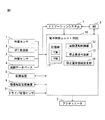
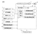
図1は本発明による第1実施例の移動体の自動運転制御システムのブロック図を示している。移動体は車両や移動ロボットなどを含む。以下では、移動体が車両である場合を例にとって説明する。図1を参照すると、車両の自動運転制御システムは外部センサ1、GPS受信部2、内部センサ3、地図データベース4、記憶装置5、環境地図記憶装置6、ナビゲーションシステム7、HMI(Human Machine Interface)8、種々のアクチュエータ9、電子制御ユニット(ECU,Electronic Computer Unit)10、及びドライバ状態センサ21を備える。
FIG. 1 shows a block diagram of an automatic driving control system for a moving body according to a first embodiment of the present invention. The moving body includes a vehicle and a mobile robot. Hereinafter, a case where the moving body is a vehicle will be described as an example. Referring to FIG. 1, an automatic driving control system for a vehicle includes an external sensor 1, a
外部センサ1は自車両の外部又は周囲の情報を検出するための検出機器である。外部センサ1はライダー(LIDAR:Laser Imaging Detection and Ranging)、レーダー(Radar)、及びカメラのうち少なくとも1つを備える。本発明による第1実施例では図2に示されるように、外部センサ1は、少なくとも1つのライダーSO1、少なくとも1つのレーダーSO2、及び少なくとも1つのカメラSO3を備える。 The external sensor 1 is a detection device for detecting information outside or around the host vehicle. The external sensor 1 includes at least one of a rider (LIDAR: Laser Imaging Detection and Ranging), a radar (Radar), and a camera. In the first embodiment according to the present invention, as shown in FIG. 2, the external sensor 1 includes at least one rider SO1, at least one radar SO2, and at least one camera SO3.
ライダーSO1はレーザー光を利用して自車両Vの外部の物体を検出する装置である。本発明による第1実施例では、物体は、移動不能な物体である静的物体(例えば、建物、道路など)、移動可能な物体である動的物体(例えば、他車両、歩行者など)、基本的には移動不能であるが容易に移動可能な物体である準静的物体(例えば、立て看板、ゴミ箱、樹木の枝など)を含む。図2に示される例では、単一のライダーSO1が車両Vの屋根上に設置される。別の実施例(図示しない)では、例えば4つのライダーが車両Vの四隅においてバンパーにそれぞれ取り付けられる。ライダーSO1は、自車両Vの全周囲に向けてレーザー光を順次照射し、その反射光から物体に関する情報を計測する。この物体情報はライダーSO1から物体までの距離及び向き、すなわちライダーSO1に対する物体の相対位置を含む。ライダーSO1により検出された物体情報は電子制御ユニット10へ送信される。一方、レーダーSO2は、電波を利用して自車両Vの外部の物体を検出する装置である。図2に示される例では、例えば4つのレーダーSO2が車両Vの四隅においてバンパーにそれぞれ取り付けられる。レーダーSO2は、レーダーSO2から自車両Vの周囲に電波を発射し、その反射波から自車両Vの周囲の物体に関する情報を計測する。レーダーSO2により検出された物体情報は電子制御ユニット10へ送信される。カメラSO3は図2に示される例では、車両Vのフロントガラスの内側に設けられた単一のステレオカメラを備える。ステレオカメラSO3は自車両Vの前方をカラー又はモノクロ撮影し、ステレオカメラSO3によるカラー又はモノクロ撮影情報は電子制御ユニット10へ送信される。
The rider SO1 is a device that detects an object outside the host vehicle V using laser light. In the first embodiment according to the present invention, the object is a static object (for example, a building or a road) that is an immovable object, a dynamic object (for example, another vehicle, a pedestrian, or the like) that is a movable object, Basically, it includes a quasi-static object (for example, a standing signboard, a trash can, a tree branch, etc.) that is an object that is immovable but easily movable. In the example shown in FIG. 2, a single rider SO <b> 1 is installed on the roof of the vehicle V. In another embodiment (not shown), for example, four riders are respectively attached to the bumpers at the four corners of the vehicle V. The rider SO1 sequentially irradiates laser light toward the entire periphery of the host vehicle V, and measures information related to the object from the reflected light. This object information includes the distance and direction from the rider SO1 to the object, that is, the relative position of the object with respect to the rider SO1. Object information detected by the rider SO1 is transmitted to the
再び図1を参照すると、GPS受信部2は、3個以上のGPS衛星からの信号を受信し、それにより自車両又は外部センサ1の絶対位置(例えば自車両Vの緯度、経度及び高度)を表す情報を検出する。GPS受信部2により検出された自車両の絶対位置情報は電子制御ユニット10へ送信される。
Referring to FIG. 1 again, the
内部センサ3は、自車両Vの走行状態を検出するための検出機器である。自車両Vの走行状態は、自車両の速度、加速度、及び姿勢のうち少なくとも1つにより表される。内部センサ3は、車速センサ及びIMU(Inertial Measurement Unit)の一方又は両方を備える。本発明による第1実施例では内部センサ3は車速センサ及びIMUを備える。車速センサは、自車両Vの速度を検出する。IMUは例えば3軸のジャイロ及び3方向の加速度センサを備え、自車両Vの3次元の角速度及び加速度を検出し、それらに基づいて自車両Vの加速度及び姿勢を検出する。内部センサ3により検出された自車両Vの走行状態情報は電子制御ユニット10へ送信される。
The
地図データベース4は、地図情報に関するデータベースである。この地図データベース4は例えば車両に搭載されたHDD(Hard disk drive)内に記憶されている。地図情報には、例えば道路の位置情報、道路形状の情報(例えば、カーブと直線部の種別、カーブの曲率、交差点、合流点及び分岐点の位置など)などが含まれる。
The
記憶装置5には、ライダーSO1により検出された物体の三次元画像及びライダーSO1の検出結果に基づき作成された自動運転専用の道路地図が記憶されている。これら物体の三次元画像及び道路地図は常時又は定期的に更新される。
The
環境地図記憶装置6には環境地図情報(後述する)が記憶されている。
The environmental
ナビゲーションシステム7は、HMI8を介し自車両Vのドライバによって設定された目的地まで自車両Vを案内する装置である。このナビゲーションシステム7は、GPS受信部2により検出された自車両Vの現在の位置情報と地図データベース4の地図情報とに基づいて、目的地に至るまでの目標ルートを演算する。この自車両Vの目標ルートの情報は電子制御ユニット10へ送信される。
The
HMI8は、自車両Vの乗員と車両の自動運転制御システムとの間で情報の出力及び入力を行うためのインターフェイスである。本発明による第1実施例ではHMI8は、文字又は画像情報を表示するディスプレイ、音を発生するスピーカ、及び乗員が入力操作を行うための操作ボタン、タッチパネル、又は音声認識装置(マイク)を備える。
The
アクチュエータ9は、電子制御ユニット10からの制御信号に応じて自車両Vの走行操作を制御するための装置である。車両Vの走行操作には車両Vの駆動、制動及び操舵が含まれる。アクチュエータ9は、駆動アクチュエータ、制動アクチュエータ、及び操舵アクチュエータのうちの少なくとも1つを備える。駆動アクチュエータは、車両Vの駆動力を提供するエンジン又は電気モータの出力を制御し、それにより車両Vの駆動操作を制御する。制動アクチュエータは、車両Vの制動装置を操作し、それにより車両Vの制動操作を制御する。操舵アクチュエータは、車両Vの操舵装置を操作し、それにより車両Vの操舵操作を制御する。
The
自動運転が可能な状態において、HMI8において乗員により自動運転を開始すべき入力操作がなされると、電子制御ユニット10に信号が送られて自動運転が開始される。すなわち、車両Vの走行操作である駆動、制動及び操舵がアクチュエータ9により制御される。一方、HMI8において乗員により自動運転を停止すべき入力操作がなされると、電子制御ユニット10に信号が送られて自動運転が停止され、車両Vの走行操作の少なくとも1つがドライバにより行われるマニュアル運転が開始される。言い換えると、自動運転からマニュアル運転に切り換えられる。なお、自動運転時にドライバにより車両Vの走行操作が行なわれたとき、すなわちドライバがステアリングをあらかじめ定められたしきい量以上操作したとき、アクセルペダルをあらかじめ定められたしきい量以上踏み込んだとき、又は、ブレーキペダルをあらかじめ定められたしきい量以上踏み込んだときにも、自動運転からマニュアル運転に切り換えられる。更に、自動運転中に自動運転が困難と判断されたときには、HMI7を介してドライバに対しマニュアル運転が要求される。
In the state where automatic driving is possible, when an input operation for starting automatic driving is performed by the occupant in the
電子制御ユニット10は、双方向性バスによって相互に接続されたCPU(Central Processing Unit)、ROM(Read Only Memory)、RAM(Random Access Memory)などを備えたコンピュータである。図1に示されるように、本発明による第1実施例の電子制御ユニット10は、ROM及びRAMを有する記憶部11、自動運転制御部12、停止要求判定部13、及び停止適合領域決定部14を備える。
The
自動運転制御部12は、車両Vの自動運転を制御するように構成されている。停止要求判定部13は、車両Vを停止すべきか否かを判定するように構成されている。停止適合領域決定部14は、環境地図記憶装置6内の環境地図情報に基づいて、車両Vが停止するのに適した停止適合領域を決定するように構成されている。
The automatic
本発明による第1実施例では、自動運転制御部12は図3に示されるように、周辺認識部12a、自己位置決定部12b、進路生成部12c、及び移動制御部12dを備える。
In the first embodiment of the present invention, as shown in FIG. 3, the automatic
周辺認識部12aは、外部センサ1を用いて、自車両Vの周辺の状況を認識するように構成されている。すなわち、周辺認識部12aは、外部センサ1の検出結果(例えば、ライダーSO1による物体の三次元画像情報、レーダーSO2による物体情報、カメラSO3による撮影情報など)に基づいて、自車両Vの周辺状況を認識する。この外部状況には、例えば、自車両Vに対する走行車線の白線の位置、車両Vに対する車線中心の位置、道路幅、道路の形状(例えば、走行車線の曲率、路面の勾配変化など)、車両Vの周辺の物体の状況(例えば、静的物体と動的物体を区別する情報、車両Vに対する物体の位置、車両Vに対する物体の移動方向、車両Vに対する物体の相対速度など)が含まれる。
The
自己位置決定部12bは、自車両Vの絶対位置を決定するように構成されている。すなわち、自己位置決定部12bは、GPS受信部2からの自車両Vのおおまかな位置と、周辺認識部12aにより認識された自車両Vの周辺状況と、記憶装置5内に記憶されている物体に関する情報及び自動運転専用の道路地図とに基づいて、自車両Vの正確な絶対位置を算出する。
The self-
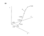
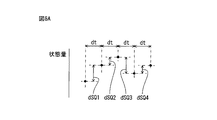
進路生成部12cは、車両Vの進路を生成するように構成されている。本発明による第1実施例では、進路は、時間tを表す情報と、当該時間tにおける車両の絶対位置(x(t),y(t))を表す情報と、当該時間tにおける車両の走行状態(例えば、速度v(t)及び進行方向θ(t))を表す情報との組合せ(t,x(t),y(t),v(t),θ(t))を含む。ここで、x(t)は例えば緯度により表され、y(t)は例えば経度により表される。例えば、まず、現在時刻(t=0)における組合せ(0,x(0),y(0),v(0),θ(0))を用いて、時間Δtが経過した後の組合せ(Δt,x(Δt),y(Δt),v(Δt),θ(Δt))が算出される。次いで、更に時間Δtが経過した後の組合せ(2Δt,x(2Δt),y(2Δt),v(2Δt),θ(2Δt))が算出される。次いで、更に時間nΔが経過した後の組合せ(nΔt,x(nΔt),y(nΔt),v(nΔt),θ(nΔt))が算出される。これらの組合せの一例が図4に示されている。すなわち図4は、時間t及び車両Vの絶対位置(x(t),y(t))により規定された三次元空間内に上述の組合せ(t,x(t),y(t),v(t),θ(t))の一例をプロットしたものである。図4に示されるように、複数の組合せ(t,x(t),y(t),v(t),θ(t))を順次結んで得られる曲線が進路Pとなる。 The course generation unit 12c is configured to generate a course of the vehicle V. In the first embodiment according to the present invention, the course is information indicating the time t, information indicating the absolute position (x (t), y (t)) of the vehicle at the time t, and traveling of the vehicle at the time t. A combination (t, x (t), y (t), v (t), θ (t)) with information representing a state (for example, speed v (t) and traveling direction θ (t)) is included. Here, x (t) is represented by latitude, for example, and y (t) is represented by longitude, for example. For example, first, using the combination (0, x (0), y (0), v (0), θ (0)) at the current time (t = 0), the combination after the time Δt has elapsed (Δt , X (Δt), y (Δt), v (Δt), θ (Δt)) are calculated. Next, a combination (2Δt, x (2Δt), y (2Δt), v (2Δt), θ (2Δt)) after the time Δt has elapsed is calculated. Next, a combination (nΔt, x (nΔt), y (nΔt), v (nΔt), θ (nΔt)) after the time nΔ has elapsed is calculated. An example of these combinations is shown in FIG. That is, FIG. 4 shows the above-described combination (t, x (t), y (t), v in the three-dimensional space defined by the time t and the absolute position (x (t), y (t)) of the vehicle V. An example of (t), θ (t)) is plotted. As shown in FIG. 4, a curve obtained by sequentially connecting a plurality of combinations (t, x (t), y (t), v (t), θ (t)) is the course P.
移動制御部12dは、車両Vの移動制御を行うように構成されている。具体的には、移動制御部12dは、進路生成部12cにより生成された進路Pに沿って移動するように車両Vを制御するように構成されている。すなわち、移動制御部12dは、進路Pが有する組合せ(t,x(t),y(t),v(t),θ(t))が実現されるようにアクチュエータ9を制御して、車両Vの駆動、制動及び操舵を制御する。
The
ドライバ状態センサ21はドライバの状態を検出するための検出機器である。ドライバの状態は例えば、ドライバの外観及び内部状態の一方又は両方により表される。ドライバの外観は例えば、ドライバの視線、ドライバの瞼の状態、ドライバの顔の向き、ドライバの姿勢、のうちの少なくとも1つにより表される。ドライバの姿勢は、ドライバの身体の位置又は向き、ドライバの手の位置などによって表わされる。一方、ドライバの内部状態は例えば、ドライバの心拍数、血圧、皮膚電位のような生理的指標により表される。ドライバの状態がドライバの視線、ドライバの瞼の状態、ドライバの顔の向き、ドライバの姿勢、などにより表される場合には、ドライバ状態センサは、例えば車両Vの内部に取り付けられたドライバカメラを備える。このドライバカメラはドライバを撮影する。ドライバの状態がドライバの内部状態により表わされる場合には、ドライバ状態センサ21は、例えばステアリングに取り付けられた内部状態センサを備える。この内部状態センサは例えばドライバの生理的指標を検出する。ドライバ状態センサ21により検出されたドライバの状態情報は電子制御ユニット10へ送信される。
The
本発明による第1実施例では、停止要求判定部13は、ドライバ状態センサ21により検出されたドライバ状態に基づいて、車両Vを停止すべきか否かを判定するように構成されている。具体的には、ドライバがマニュアル運転を行うことができない状態にあるか否かが判定される。例えば、ドライバが死亡状態又は失神状態にあるときに、ドライバがマニュアル運転を行うことができない状態にあると判定される。ドライバがマニュアル運転を行うことができない状態にあると判定されたときには、車両Vを停止すべきと判定される。言い換えると、車両Vの停止要求が出力される。これに対し、ドライバがマニュアル運転を行うことができない状態にあると判定されないときには、車両Vの停止要求は出力されない。
In the first embodiment according to the present invention, the stop
停止要求判定部13から車両Vの停止要求が出力されると、停止適合領域決定部14は、環境地図記憶装置6内の環境地図情報に基づいて、停止適合領域を決定する。次いで、進路生成部12cは、車両Vが停止適合領域内に停止するように進路Pを生成する。次いで、移動制御部12dは、車両Vが進路Pに沿って移動するように車両Vを制御する。その結果、車両Vが停止適合領域内に自動的に停止される。このようにして緊急避難が行われる。
When a stop request for the vehicle V is output from the stop
一方、停止要求判定部13から車両Vの停止要求が出力されないときには、進路生成部12cは、通常の進路Pを生成する。すなわち、車両Vが上述の目標ルートに従って移動するように、進路Pが生成される。この場合、進路Pは、法令を順守しつつ、安全にかつ最短時間で目的地に到達するように生成される。
On the other hand, when a stop request for the vehicle V is not output from the stop
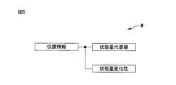
次に、本発明による第1実施例の環境地図情報を説明する。図5は本発明による第1実施例の環境地図情報Mを概略的に示している。本発明による第1実施例の環境地図情報Mは図5に示されるように、空間内の複数の位置をそれぞれ表す位置情報と、それぞれ対応する位置情報と関連付けられた状態量代表値と、それぞれ対応する位置情報と関連付けられた状態量変化性と、を有する。なお、本発明による第1実施例では、上述の空間は三次元空間である。別の実施例(図示しない)では、空間は二次元空間である。 Next, environmental map information according to the first embodiment of the present invention will be described. FIG. 5 schematically shows the environmental map information M of the first embodiment according to the present invention. As shown in FIG. 5, the environmental map information M of the first embodiment according to the present invention includes position information representing a plurality of positions in space, state quantity representative values associated with corresponding position information, and State quantity variability associated with corresponding position information. In the first embodiment according to the present invention, the above-described space is a three-dimensional space. In another embodiment (not shown), the space is a two-dimensional space.
或る位置の状態量代表値及び状態量変化性は、当該或る位置の状態量に基づいて算出されるものである。本発明による第1実施例では、或る位置の状態量は、当該或る位置に物体が存在する確率により表される。この場合、状態量は例えば、ゼロから1までの連続値の形で算出される。別の実施例(図示しない)では、状態量は離散値の形で算出される。 The state quantity representative value and the state quantity changeability at a certain position are calculated based on the state quantity at the certain position. In the first embodiment according to the present invention, the state quantity at a certain position is represented by the probability that an object exists at the certain position. In this case, the state quantity is calculated, for example, in the form of continuous values from zero to one. In another embodiment (not shown), the state quantity is calculated in the form of discrete values.
或る位置の状態量代表値は、当該或る位置の状態を適切に表す数値である。本発明による第1実施例では、状態量代表値は、例えば、ゼロから1までの連続値の形で算出される。別の実施例(図示しない)では、状態量代表値は離散値の形で算出される。 The state quantity representative value at a certain position is a numerical value that appropriately represents the state at the certain position. In the first embodiment according to the present invention, the state quantity representative value is calculated, for example, in the form of a continuous value from zero to one. In another embodiment (not shown), the state quantity representative value is calculated in the form of discrete values.
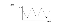
一方、或る位置の状態量変化性は、当該或る位置の状態量の時間に対する変化のしやすさを表す数値である。本発明による第1実施例では、状態量変化性は、連続値の形で算出される。別の実施例(図示しない)では、状態量変化性は離散値の形で算出される。次に、図6A、図6B、及び図6Cを参照して、状態量変化性を更に説明する。なお、図6A、図6B、及び図6Cにおいて、検出された状態量がプロットされている。 On the other hand, the state quantity variability at a certain position is a numerical value representing the ease of change of the state quantity at a certain position with respect to time. In the first embodiment according to the present invention, the state quantity variability is calculated in the form of a continuous value. In another embodiment (not shown), the state quantity variability is calculated in the form of discrete values. Next, the state quantity variability will be further described with reference to FIGS. 6A, 6B, and 6C. In FIG. 6A, FIG. 6B, and FIG. 6C, the detected state quantities are plotted.
状態量変化性は、例えば、時間に対する状態量の変化の頻度や変化の程度などによって表される。すなわち、図6Bに示される例の状態量は、図6Aに示される例の状態量に比べて、変化の頻度が高く、時間に対し変化しやすい。したがって、図6Bに示される例の状態量変化性は、図6Aに示される例の状態量変化性よりも高い。一方、図6Cに示される例の状態量は、図6Aに示される例の状態量に比べて、変化の程度が大きく、時間に対し変化しやすい。したがって、図6Cに示される例の状態量変化性は、図6Aに示される例の状態量変化性よりも高い。 The state quantity variability is represented by, for example, the frequency of change of the state quantity with respect to time and the degree of change. That is, the state quantity in the example shown in FIG. 6B has a higher frequency of change than the state quantity in the example shown in FIG. 6A and is likely to change with time. Therefore, the state quantity variability in the example shown in FIG. 6B is higher than the state quantity variability in the example shown in FIG. 6A. On the other hand, the state quantity in the example shown in FIG. 6C has a greater degree of change and is likely to change with time as compared to the state quantity in the example shown in FIG. 6A. Therefore, the state quantity variability in the example shown in FIG. 6C is higher than the state quantity variability in the example shown in FIG. 6A.
次に、環境地図情報Mの作成例を説明する。この作成例では、空間内の位置を表す位置情報と位置の状態量とを検出する環境検出装置と、環境地図用の記憶装置と、環境地図作成用の電子制御ユニットと、を備え、環境地図作成用の電子制御ユニットは、空間内の複数の位置のそれぞれについて、前記位置を表す位置情報と、互いに異なる時刻における前記位置の状態量とを前記環境検出装置により検出するように構成されている環境検出部と、前記複数の位置のそれぞれについて、検出された前記状態量を用いて前記状態量代表値を算出する状態量算出部と、前記複数の位置のそれぞれについて、検出された前記状態量を用いて前記状態量変化性を算出するように構成されている変化性算出部と、前記状態量代表値及び前記状態量変化性をそれぞれ対応する前記位置情報と関連付けて環境地図用の記憶装置に記憶する記憶部と、を備えた環境地図作成システムを用いて、環境地図情報Mが作成される。環境地図作成システムは車両のような移動体に搭載される。環境検出装置は、例えば、環境地図作成システムの周囲の物体を検出する外部センサ(例えば、ライダー)と、内部センサと、環境地図作成システムの絶対位置を検出するGPS受信部と、を備える。 Next, an example of creating the environmental map information M will be described. This creation example includes an environment detection device that detects position information indicating a position in space and a state quantity of the position, a storage device for an environment map, and an electronic control unit for creating an environment map, The electronic control unit for creation is configured to detect position information representing the position and a state quantity of the position at different times by the environment detection device for each of a plurality of positions in the space. An environment detection unit; a state quantity calculation unit that calculates the state quantity representative value using the detected state quantity for each of the plurality of positions; and the state quantity detected for each of the plurality of positions. A change calculating unit configured to calculate the state quantity variability by using the state quantity representative value and the state quantity variability in association with the corresponding position information. A storage unit for storing in a storage device boundary map, using the environmental map creation systems with environmental map information M is created. The environmental mapping system is mounted on a moving body such as a vehicle. The environment detection device includes, for example, an external sensor (for example, a rider) that detects an object around the environment map creation system, an internal sensor, and a GPS receiver that detects the absolute position of the environment map creation system.
図7は、環境地図作成システムのライダーLから照射されたレーザー光が物体OBJで反射した場合を示している。この場合、図7に黒丸で示されるように、位置PXに反射点が形成される。ライダーLは、反射光から、反射点の位置PXの相対位置情報を計測する。この計測結果から、位置PXに物体OBJが存在するということがわかり、したがって位置PXの状態量、すなわち物体存在確率は1となる。また、ライダー1からの位置PXの相対位置情報と、環境地図作成システムのGPS受信部からの環境地図作成システムの絶対位置情報とから、位置PXの絶対位置情報がわかる。更に、図7に白丸で示される反射点でない位置PYに物体が存在しないということがわかり、したがって位置PYの状態量すなわち物体存在確率はゼロとなる。また、ライダーLからの位置PXの相対位置情報と、環境地図作成システムのGPS受信部からの環境地図作成システムの絶対位置情報とから、位置PYの絶対位置情報がわかる。このようにして、位置PX,PYの絶対位置情報及び状態量が算出される。 FIG. 7 shows a case where the laser beam emitted from the rider L of the environment mapping system is reflected by the object OBJ. In this case, as indicated by a black circle in FIG. 7, a reflection point is formed at the position PX. The rider L measures the relative position information of the reflection point position PX from the reflected light. From this measurement result, it can be seen that the object OBJ exists at the position PX. Therefore, the state quantity at the position PX, that is, the object existence probability is 1. Further, the absolute position information of the position PX is obtained from the relative position information of the position PX from the rider 1 and the absolute position information of the environmental map creation system from the GPS receiver of the environmental map creation system. Further, it can be seen that there is no object at the position PY which is not a reflection point indicated by a white circle in FIG. 7, and therefore the state quantity at the position PY, that is, the object existence probability is zero. Further, the absolute position information of the position PY is known from the relative position information of the position PX from the rider L and the absolute position information of the environmental map creation system from the GPS receiver of the environmental map creation system. In this way, the absolute position information and state quantities of the positions PX and PY are calculated.
環境地図情報Mの作成例では、環境地図作成システムのライダーLは物体情報を例えば数十msのインターバルで繰り返し検出する。言い換えると、環境地図作成システムのライダーLは、互いに異なる複数の時刻における物体情報を検出する。したがって、互いに異なる複数の時刻における物体情報から、互いに異なる複数の時刻における状態量が算出される。あるいは、環境地図作成システムを搭載した移動体が一定の場所を複数回移動した場合にも、互いに異なる複数の時刻における物体情報が検出され、したがって互いに異なる複数の時刻における状態量が算出される。図8A、図8B、及び図8Cには、互いに異なる複数の時刻における、或る位置の状態量の種々の例が示されている。 In the example of creating the environmental map information M, the rider L of the environmental map creating system repeatedly detects the object information at intervals of several tens of ms, for example. In other words, the rider L of the environmental map creation system detects object information at a plurality of different times. Therefore, state quantities at a plurality of different times are calculated from object information at a plurality of different times. Alternatively, even when a moving body equipped with the environment map creation system moves a certain place a plurality of times, object information at a plurality of different times is detected, and thus state quantities at a plurality of different times are calculated. 8A, 8B, and 8C show various examples of state quantities at a certain position at a plurality of different times.
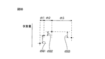
環境地図情報Mの作成例では、状態量の単位時間当たりの変化量が算出され、状態量の単位時間当たりの変化量に基づいて状態量変化性が算出される。すなわち、図8Aに示される例では、同一の時間幅dtにおける状態量の変化量(絶対値)dSQ1,dSQ2,…が算出される。この場合の時間幅dtは、例えば、状態量の検出間隔に等しい。なお、図8Aに示される例では、連続した時間幅dtにおいて状態量の変化量dSQ1,dSQ2,…がそれぞれ算出されるけれども、別の例では、不連続の時間幅dtにおいて状態量の変化量がそれぞれ算出される。あるいは、図8Bに示される例では、互いに異なる複数の時間幅dt1,dt2,…における状態量の変化量(絶対値)dSQ1,dSQ2,…がそれぞれ算出される。異なる時間幅は例えば、秒、分、日、年といったオーダーである。次いで、状態量の単位時間当たりの変化量dSQ1/dt1,dSQ2/dt2,…が順次算出される。なお、図8Bに示される例では、連続した時間幅dt1,dt2,…において状態量の変化量dSQ1,dSQ2,…がそれぞれ算出されるけれども、別の例では、不連続の時間幅において状態量の変化量がそれぞれ算出される。次いで、状態量の単位時間当たりの変化量dSQ1/dt1,dSQ2/dt2,…を単純平均又は加重平均することにより、状態量変化性が算出される。加重平均が用いられる場合、一例では、検出時期がより新しい状態量の単位時間当たりの変化量dSQ/dtがより大きく重み付けされ、検出時期がより古い状態量の単位時間当たりの変化量dSQ/dtがより小さく重み付けされる。別の例では、検出時期がより新しい状態量の単位時間当たりの変化量dSQ/dtがより小さく重み付けされ、検出時期がより古い状態量の単位時間当たりの変化量dSQ/dtがより大きく重み付けされる。このような状態量変化性の算出が複数の位置についてそれぞれ行われる。 In the example of creating the environmental map information M, the amount of change of the state quantity per unit time is calculated, and the state quantity variability is calculated based on the amount of change of the state quantity per unit time. That is, in the example shown in FIG. 8A, the amount of change (absolute value) dSQ1, dSQ2,... Of the state quantity in the same time width dt is calculated. The time width dt in this case is equal to, for example, the state quantity detection interval. In the example shown in FIG. 8A, the state quantity change amounts dSQ1, dSQ2,... Are calculated in the continuous time width dt, but in another example, the state quantity change amount in the discontinuous time width dt. Are calculated respectively. Alternatively, in the example shown in FIG. 8B, the amount of change (absolute value) dSQ1, dSQ2,... Of state quantities in a plurality of mutually different time widths dt1, dt2,. The different time widths are, for example, orders such as seconds, minutes, days, years. Next, change amounts dSQ1 / dt1, dSQ2 / dt2,... Of the state quantity per unit time are sequentially calculated. In the example shown in FIG. 8B, the state quantity change amounts dSQ1, dSQ2,... Are calculated in the continuous time widths dt1, dt2,. Are calculated respectively. Next, the state quantity variability is calculated by performing a simple average or a weighted average of the amount of change dSQ1 / dt1, dSQ2 / dt2,. When the weighted average is used, in one example, the change amount dSQ / dt of the state quantity with a newer detection time is more heavily weighted, and the change amount dSQ / dt of the state quantity with an older detection time is weighted. Is weighted smaller. In another example, the amount of change dSQ / dt per unit time of a state quantity with a newer detection time is weighted smaller, and the amount of change dSQ / dt of a state quantity with an older detection time is weighted more. The Such calculation of state quantity variability is performed for each of a plurality of positions.
環境地図情報Mの別の作成例(図示しない)では、時間の関数としての複数の状態量がフーリエ変換され、その結果から状態量変化性が算出される。具体的には、一例では、あらかじめ定められたスペクトル(周波数)の強度が状態量変化性として算出される。別の例では、種々のスペクトルの強度を単純平均又は加重平均することにより状態量変化性が算出される。 In another example of creating the environmental map information M (not shown), a plurality of state quantities as a function of time are Fourier transformed, and state quantity variability is calculated from the result. Specifically, in one example, the intensity of a predetermined spectrum (frequency) is calculated as the state quantity variability. In another example, the state quantity variability is calculated by simple averaging or weighted averaging of the intensities of various spectra.
一方、環境地図情報Mの作成例では、状態量代表値は、互いに異なる複数の時刻において検出された当該或る位置の状態量に基づいて算出される。一例では、或る位置の状態量代表値は、互いに異なる複数の時刻における当該或る位置の状態量のうち、最新のものに設定される。このようにすると、或る位置の状態量代表値は、当該或る位置の最新の状態を表すことになる。別の例では、或る位置の状態量代表値は、互いに異なる複数の時刻における当該或る位置の状態量を単純平均又は加重平均することにより算出される。このようにすると、或る位置の状態量が一時的に変わったとしても、状態量代表値により、当該位置の状態を正確に表すことができる。 On the other hand, in the example of creating the environmental map information M, the state quantity representative value is calculated based on the state quantity of the certain position detected at a plurality of different times. In one example, the state quantity representative value at a certain position is set to the latest value among the state quantities at the certain position at a plurality of different times. In this way, the state quantity representative value at a certain position represents the latest state at the certain position. In another example, the state quantity representative value at a certain position is calculated by performing a simple average or a weighted average of the state quantities at a certain position at a plurality of different times. In this way, even if the state quantity at a certain position temporarily changes, the state at that position can be accurately represented by the state quantity representative value.
次いで、状態量代表値がそれぞれ対応する位置情報と関連付けられて環境地図用の記憶装置内に記憶される。また、状態量変化性がそれぞれ対応する位置情報と関連付けられて環境地図用の記憶装置内に記憶される。このようにして環境地図情報Mが作成される。 Next, the state quantity representative values are stored in the storage device for the environmental map in association with the corresponding position information. The state quantity variability is stored in the environmental map storage device in association with the corresponding position information. In this way, the environmental map information M is created.
このように状態量代表値及び状態量変化性が位置情報と関連付けられているので、位置情報を指定すると、環境地図情報Mから、対応する位置の状態量代表値及び状態量変化性がわかる。なお、本発明による第1実施例では、環境地図情報Mは、三次元空間内の位置の位置情報、状態量代表値、及び状態量変化性を有するので、三次元地図である。また、本発明による第1実施例では、位置情報は絶対位置情報である。別の実施例(図示しない)では、位置情報はあらかじめ定められた特定の位置に対する相対位置情報である。 Since the state quantity representative value and the state quantity variability are associated with the position information in this way, when the position information is designated, the state map representative value and the state quantity variability of the corresponding position can be known from the environment map information M. In the first embodiment according to the present invention, the environment map information M is a three-dimensional map because it has position information of a position in the three-dimensional space, a state quantity representative value, and a state quantity variability. In the first embodiment according to the present invention, the position information is absolute position information. In another embodiment (not shown), the position information is relative position information with respect to a predetermined specific position.
このようにして作成された環境地図情報Mから、次のことがわかる。すなわち、或る位置の、物体存在確率により表される状態量が大きく、状態量変化性が低い場合には、当該位置は、静的物体(例えば、建物、道路面など)、又は、静止している動的物体(例えば、他車両、歩行者など)もしくは準静的物体(例えば、立て看板、ゴミ箱、樹木の枝など)により占有されている。あるいは、当該位置が動的物体又は準静的物体により占有されている占有状態と、当該位置が動的物体又は準静的物体により占有されていない非占有状態とが比較的低い頻度で切り換わると共に、占有状態の時間が比較的長い。一方、或る位置の状態量が小さく状態量変化性が低い場合には、当該位置には、何も存在していない。そのような位置の具体例は、池の上方空間などである。或る位置の状態量が大きく状態量変化性が高い場合には、当該位置では占有状態と非占有状態とが比較的高い頻度で切り換わると共に、占有状態の時間が比較的長い。そのような位置の具体例は、交通量が比較的多い道路などである。或る位置の状態量が小さく状態量変化性が高い場合には、当該位置では占有状態と非占有状態とが比較的高い頻度で切り換わると共に、非占有状態の時間が比較的長い。そのような位置の具体例は、交通量が比較的少ない(ゼロではない)道路などである。 From the environmental map information M created in this way, the following can be understood. That is, when the state quantity represented by the object existence probability at a certain position is large and the state quantity changeability is low, the position is static object (for example, building, road surface, etc.) or stationary. Or a quasi-static object (eg, a standing signboard, a trash can, a tree branch, etc.). Alternatively, the occupied state in which the position is occupied by a dynamic object or a quasi-static object and the unoccupied state in which the position is not occupied by a dynamic object or a quasi-static object are switched at a relatively low frequency. At the same time, the occupied time is relatively long. On the other hand, when the state quantity at a certain position is small and the state quantity changeability is low, there is nothing at that position. A specific example of such a position is an upper space of a pond. When the state quantity at a certain position is large and the state quantity changeability is high, the occupied state and the unoccupied state are switched at a relatively high frequency at the position, and the occupied state time is relatively long. A specific example of such a position is a road having a relatively large traffic volume. When the state quantity at a certain position is small and the state quantity changeability is high, the occupied state and the unoccupied state are switched at a relatively high frequency at the position, and the time of the unoccupied state is relatively long. A specific example of such a position is a road with a relatively small traffic volume (not zero).
すなわち、本発明による第1実施例の環境地図情報Mには、或る位置における物体又は物体の存在の有無に関する情報だけでなく、当該位置がどのような状況にあるかの情報も含まれている。したがって、空間内の状況をより正確に表すことができる。 That is, the environmental map information M according to the first embodiment of the present invention includes not only information regarding the presence of an object or the presence of an object at a certain position, but also information on the situation of the position. Yes. Therefore, the situation in the space can be expressed more accurately.
なお、本発明による第1実施例では、環境地図作成システムを搭載した移動体は、車両Vとは別の移動体である。別の実施例(図示しない)では、環境地図作成システムを搭載した移動体は、車両Vである。すなわち、車両Vにおいて環境地図情報Mが作成され、環境地図記憶装置6内に記憶される。この場合、車両Vの外部センサ1及びGPS受信部2は、環境地図作成システムの環境検出装置を構成する。
In the first embodiment according to the present invention, the moving body equipped with the environmental map creating system is a moving body different from the vehicle V. In another embodiment (not shown), the mobile body equipped with the environmental map creation system is a vehicle V. That is, the environmental map information M is created in the vehicle V and stored in the environmental
また、上述した本発明による第1実施例では、或る位置の状態量は当該或る位置に物体が存在する確率により表される。別の実施例(図示しない)では、或る位置の状態量は、或る位置に存在する物体の色又は輝度値により表される。この場合、例えば、信号機のランプのうちどのランプが点灯しているかを把握することができる。この別の実施例では、状態量が物体の色により表わされる場合には、物体の色は、外部センサ1のカメラSO3としてのカラーカメラにより検出される。一方、状態量が物体の輝度値により表わされる場合には、物体の輝度値は、外部センサ1のライダーSO1、レーダーSO2、又は、カラーもしくはモノクロカメラSO3により検出される。すなわち、ライダーSO1から発射されたレーザー光が物体に反射したときに得られる反射光の強度は当該物体の輝度値を表している。同様に、レーダーSO2の反射波強度は物体の輝度値を表している。したがって、反射光強度又は反射波強度を検出することにより、物体の輝度値が検出される。なお、状態量が物体の色により表される場合、状態量は、例えばRGBモデルを用いて数値化される。 In the first embodiment according to the present invention described above, the state quantity at a certain position is represented by the probability that an object exists at the certain position. In another embodiment (not shown), the state quantity at a certain position is represented by the color or luminance value of an object present at the certain position. In this case, for example, it is possible to grasp which lamp is lit among the lamps of the traffic light. In this alternative embodiment, when the state quantity is represented by the color of the object, the color of the object is detected by a color camera as the camera SO3 of the external sensor 1. On the other hand, when the state quantity is represented by the brightness value of the object, the brightness value of the object is detected by the rider SO1, the radar SO2, or the color or monochrome camera SO3 of the external sensor 1. That is, the intensity of the reflected light obtained when the laser light emitted from the rider SO1 is reflected by the object represents the luminance value of the object. Similarly, the reflected wave intensity of the radar SO2 represents the luminance value of the object. Therefore, the luminance value of the object is detected by detecting the reflected light intensity or the reflected wave intensity. When the state quantity is represented by the color of the object, the state quantity is digitized using, for example, an RGB model.
一方、上述した本発明による第1実施例では、1つの位置情報に1つの状態量変化性が関連付けられる。別の実施例(図示しない)では、1つの位置情報に複数の状態量変化性が関連付けられ、したがって環境地図情報Mは複数の状態量変化性を有する。この場合、一例では、図8Bに示されるような、互いに異なる複数の時間幅における状態量の変化量に基づいて、複数の状態量変化性がそれぞれ算出される。別の例では、状態量をフーリエ変換することにより得られる複数のスペクトルの強度に基づいて、複数の状態量変化性が算出される。 On the other hand, in the first embodiment according to the present invention described above, one state quantity change property is associated with one piece of position information. In another embodiment (not shown), a plurality of state quantity variability is associated with one piece of position information, and therefore the environment map information M has a plurality of state quantity variability. In this case, in one example, a plurality of state quantity variability are calculated based on the amount of change in the state quantity in a plurality of different time widths as shown in FIG. 8B. In another example, a plurality of state quantity variability are calculated based on the intensity of a plurality of spectra obtained by Fourier transforming the state quantity.
上述したように、停止適合領域決定部14は、環境地図情報Mに基づいて、停止適合領域を決定する。本発明による第1実施例では、状態量代表値があらかじめ定められた設定代表値よりも小さくかつ状態量変化性があらかじめ定められた設定変化性よりも低い第1の領域のうち、状態量代表値が設定代表値よりも大きくかつ状態量変化性が設定変化性よりも低い第2の領域に隣接する領域が、停止適合領域に決定される。
As described above, the stop suitable
上述の説明からわかるように、状態量代表値が小さくかつ状態量変化性が低い第1の領域には、物体が存在していない。したがって、第1の領域に車両Vを停止させることができる。一方、状態量代表値が大きくかつ状態量変化性が低い第2の領域には、例えば建物が存在している。このため、第2の領域の状況は安定している。これに対して、状態量変化性が高い領域及びその周辺では、状況が不安定であるおそれがある。 As can be seen from the above description, no object is present in the first region in which the state quantity representative value is small and the state quantity variability is low. Therefore, the vehicle V can be stopped in the first region. On the other hand, for example, a building exists in the second region where the state quantity representative value is large and the state quantity changeability is low. For this reason, the situation of the second region is stable. On the other hand, there is a possibility that the situation is unstable in an area where the state quantity variability is high and in the vicinity thereof.
そうすると、第2の領域に隣接する第1の領域は、車両Vの停止のために比較的安全な場所であると考えられる。そこで、本発明による第1実施例では、第2の領域に隣接する第1の領域が停止適合領域に決定される。その結果、停止適合領域をより正確に決定することができる。 Then, the first area adjacent to the second area is considered to be a relatively safe place for the vehicle V to stop. Therefore, in the first embodiment according to the present invention, the first area adjacent to the second area is determined as the stop adaptation area. As a result, the stop fit region can be determined more accurately.
なお、当然のことながら、停止適合領域は、車両Vの道路面への投影面積よりも大きな面積を有する必要がある。 As a matter of course, the stop suitable region needs to have an area larger than the projected area of the vehicle V onto the road surface.
次に、図9A及び図9Bを参照して、停止適合領域の決定方法を更に説明する。図9Aは、或る場所の平面地図を示している。図9Aにおいて、PLは植栽、BLは建物、PKは駐車場、RWは車道、RSは路肩、LMは車線、及びEMは車道外側線、をそれぞれ示している。 Next, with reference to FIG. 9A and FIG. 9B, the method of determining the stop fit region will be further described. FIG. 9A shows a planar map of a location. 9A, PL is planting, BL is a building, PK is a parking lot, RW is a roadway, RS is a roadside, LM is a lane, and EM is a roadway outer line.
図9Bは、図9Aに示される場所の種々の領域における状態量代表値及び状態量変化性の傾向を表している。すなわち、植栽PLの領域では、状態量代表値は設定代表値よりも大きく、状態量変化性は設定変化性よりも高い。図9Bではこの領域が「LL」でもって示される。一方、建物BLの領域では、状態量代表値は設定代表値よりも大きく、状態量変化性は設定変化性よりも低い。図9Bではこの領域が「LS」でもって示される。駐車場PKの領域では、状態量代表値は設定代表値よりも小さく、状態量変化性は設定変化性よりも高い。図9Bではこの領域が「SL」でもって示される。車道RWの領域では、状態量代表値は設定代表値よりも小さく、状態量変化性は設定変化性よりも高い。図9Bではこの領域が「SL」でもって示される。 FIG. 9B represents the state quantity representative value and the state quantity variability tendency in various regions in the place shown in FIG. 9A. That is, in the area of planting PL, the state quantity representative value is larger than the set representative value, and the state quantity variability is higher than the setting variability. In FIG. 9B, this region is indicated by “LL”. On the other hand, in the area of the building BL, the state quantity representative value is larger than the set representative value, and the state quantity changeability is lower than the set changeability. In FIG. 9B, this area is indicated by “LS”. In the area of the parking lot PK, the state quantity representative value is smaller than the set representative value, and the state quantity variability is higher than the setting variability. In FIG. 9B, this region is indicated by “SL”. In the area of the roadway RW, the state quantity representative value is smaller than the set representative value, and the state quantity changeability is higher than the set changeability. In FIG. 9B, this region is indicated by “SL”.
更に、路肩RSの領域のうち植栽PLに隣接する部分では、状態量代表値は設定代表値よりも小さく、状態量変化性は設定変化性よりも高い。図9Bではこの領域が「SL」でもって示される。路肩RSの領域のうち建物BLに隣接する部分では、状態量代表値は設定代表値よりも小さく、状態量変化性は設定変化性よりも低い。図9Bではこの領域が「SS」でもって示される。路肩RSの領域のうち駐車場に隣接する部分では、状態量代表値は設定代表値よりも小さく、状態量変化性は設定変化性よりも高い。駐車場PKと車道RWとの間で車両の往来があるからである。図9Bではこの領域が「SL」でもって示される。 Furthermore, in the portion adjacent to the planting PL in the road shoulder RS region, the state quantity representative value is smaller than the set representative value, and the state quantity variability is higher than the setting variability. In FIG. 9B, this region is indicated by “SL”. In the portion of the roadside RS adjacent to the building BL, the state quantity representative value is smaller than the set representative value, and the state quantity variability is lower than the setting variability. In FIG. 9B, this area is indicated by “SS”. In the portion of the roadside RS adjacent to the parking lot, the state quantity representative value is smaller than the set representative value, and the state quantity variability is higher than the setting variability. This is because there is vehicle traffic between the parking lot PK and the road RW. In FIG. 9B, this region is indicated by “SL”.
したがって、図9Bに示される例では、SSで示される領域が上述の第1の領域R1であり、LSで示される領域が上述の第2の領域R2である。このため、第2の領域R2に隣接する第1の領域R1が停止適合領域STに決定される。 Therefore, in the example shown in FIG. 9B, the region indicated by SS is the first region R1 described above, and the region indicated by LS is the second region R2 described above. For this reason, the first region R1 adjacent to the second region R2 is determined as the stop adaptation region ST.
上述したように、本発明による第1実施例では、停止要求判定部13から車両Vの停止要求が出力されたときには、進路生成部12cは、停止適合領域決定部14が決定した停止適合領域ST内に車両Vが停止するように、進路Pを生成する。
As described above, in the first embodiment of the present invention, when the stop request for the vehicle V is output from the stop
停止適合領域決定部14が1つの停止適合領域STを決定したときには、決定された停止適合領域ST内に車両Vが停止するように進路Pが生成される。一方、停止適合領域決定部14が複数の停止適合領域STを決定したときには、複数の停止適合領域STから1つの停止適合領域が選択され、選択された停止適合領域ST内に車両が停止するように進路Pが生成される。
When the stop adaptation
この場合の停止適合領域STの選択は、本発明による第1実施例では、車両Vの現在位置から停止適合領域STまでの距離に基づいて行われる。例えば、車両Vの現在位置から最も近い停止適合領域STが選択される。 In this case, the stop adaptation area ST is selected based on the distance from the current position of the vehicle V to the stop adaptation area ST in the first embodiment of the present invention. For example, the stop adaptation area ST that is closest to the current position of the vehicle V is selected.
図10には、停止適合領域決定部14により決定された複数の停止適合領域STX,STY,STZの一例が示されている。図10に示される例では、停止適合領域STX,STY,STZは、車両Vの現在位置からの距離が互いに異なっている。具体的には、停止適合領域STXは車両Vの現在位置から最も近く、停止適合領域STYは2番目に近く、停止適合領域STZは車両Vの現在位置から最も遠い。
FIG. 10 shows an example of a plurality of stop adaptation areas STX, STY, and STZ determined by the stop adaptation
したがって、本発明による第1実施例では、車両Vの現在位置から最も近い停止適合領域STXが選択される。次いで、車両Vが停止適合領域STXに停止するように進路PXが生成される。なお、車両Vの現在位置から最も近い停止適合領域STXが車両Vの走行方向に対し後方に位置する場合には、車両VはUターンする場合もある。 Therefore, in the first embodiment according to the present invention, the stop adaptation region STX closest to the current position of the vehicle V is selected. Next, a course PX is generated so that the vehicle V stops in the stop adaptation region STX. In addition, when the stop suitable area STX closest to the current position of the vehicle V is located rearward with respect to the traveling direction of the vehicle V, the vehicle V may make a U-turn.
ただし、車両Vを安全にかつ確実に停止するには、車両Vの前後方向の加速度又は減速度が一定の範囲内に維持され、車両Vの横方向の加速度又は減速度が一定の範囲内に維持されることが必要である。すなわち、車両Vの前後方向の加速度又は減速度が一定の範囲内に維持され、車両Vの横方向の加速度又は減速度が一定の範囲内に維持されるように、停止適合領域が選択される。したがって、本発明による第1実施例では、車両Vの安全で確実な停止を確保しつつ、車両Vの現在位置から最も近い停止適合領域STXが選択される。すなわち、図10の例において、車両Vを最も近い停止適合領域STXに安全にかつ確実に停止させることが困難な場合には、2番目に近い停止適合領域STYが選択され、車両Vが停止適合領域STYに停止するように進路PYが生成される。 However, in order to stop the vehicle V safely and reliably, the longitudinal acceleration or deceleration of the vehicle V is maintained within a certain range, and the lateral acceleration or deceleration of the vehicle V is within a certain range. It needs to be maintained. That is, the stop adaptation region is selected such that the longitudinal acceleration or deceleration of the vehicle V is maintained within a certain range, and the lateral acceleration or deceleration of the vehicle V is maintained within a certain range. . Therefore, in the first embodiment according to the present invention, the stop adaptation region STX closest to the current position of the vehicle V is selected while ensuring a safe and reliable stop of the vehicle V. That is, in the example of FIG. 10, when it is difficult to safely and reliably stop the vehicle V to the nearest stop adaptation region STX, the second closest stop adaptation region STY is selected, and the vehicle V is adapted to stop adaptation. A course PY is generated so as to stop in the region STY.
なお、進路Pは、車両Vが周辺認識部12aにより認識された障害物や避けて移動するように、また、車両Vが他車両の走行の障害とならないように、生成される。
The course P is generated so that the vehicle V moves while avoiding obstacles recognized by the
図11は、本発明による第1実施例の自動運転制御を実行するためのルーチンを示している。このルーチンは自動運転制御を行うべきときに繰り返し行われる。図11を参照すると、ステップ101では車両Vの停止要求が出力されているか否かが判別される。停止要求が出力されているときにはステップ102に進み、停止適合領域STが決定される。続くステップ103では、車両Vが停止適合領域STに停止するように進路Pが生成される。次いで、ステップ105に進む。これに対し、車両Vの停止要求が出力されていないときにはステップ101からステップ104に進み、通常の進路Pが生成される。次いでステップ105に進む。ステップ105では車両Vの移動制御が実行される。
FIG. 11 shows a routine for executing the automatic operation control of the first embodiment according to the present invention. This routine is repeated when automatic operation control is to be performed. Referring to FIG. 11, in
図12は、本発明による第1実施例の停止要求制御を実行するためのルーチンを示している。このルーチンは自動運転制御を行うべきときに繰り返し行われる。図12を参照すると、ステップ201では、ドライバがマニュアル運転を行うことができない状態にあるか否かが判別される。ドライバがマニュアル運転を行うことができない状態にあるときには次いでステップ202に進み、車両Vの停止要求が出力される。これに対し、ドライバがマニュアル運転を行うことができない状態にないときには、車両Vの停止要求を出力することなく、処理サイクルを終了する。
FIG. 12 shows a routine for executing the stop request control of the first embodiment according to the present invention. This routine is repeated when automatic operation control is to be performed. Referring to FIG. 12, in
次に、本発明による第2実施例を説明する。以下では、主として、本発明による第1実施例との相違点について説明する。 Next, a second embodiment according to the present invention will be described. In the following, differences from the first embodiment according to the present invention will be mainly described.
図13は本発明による第2実施例の移動体の自動運転制御システムのブロック図を示している。図13を参照すると、本発明による第2実施例の電子制御ユニット10は、災害情報受信部22を備える。災害情報受信部22は、例えばインターネットのような通信網を介して、災害情報を受信するように構成されている。災害情報は、火災、地震、津波等の災害が発生したときに、当該災害の発生地を表す情報と共に、出力される。
FIG. 13 shows a block diagram of an automatic driving control system for a moving body according to a second embodiment of the present invention. Referring to FIG. 13, the
本発明による第2実施例では、停止要求判定部13は、車両Vの現在位置から一定距離以内で発生した災害に関する災害情報を受信したときに、車両Vの停止要求を出力する。これに対し、災害情報を受信しないとき、又は、災害情報を受信したとしても災害の発生地が車両Vの現在位置から遠いときには、車両Vの停止要求は出力されない。
In the second embodiment according to the present invention, the stop
本発明による第2実施例でも、停止要求判定部13から車両Vの停止要求が出力されると、停止適合領域決定部14は、環境地図記憶装置6内の環境地図情報に基づいて、停止適合領域を決定する。次いで、進路生成部12cは、車両Vが停止適合領域内に停止するように進路Pを生成する。次いで、移動制御部12dは、車両Vが進路Pに沿って移動するように車両Vを制御する。
Also in the second embodiment according to the present invention, when a stop request for the vehicle V is output from the stop
本発明による第2実施例でも、車両Vの安全でかつ確実な停止を確保しつつ、車両Vの現在位置から最も近い停止適合領域STに車両Vが停止するように進路Pが生成される。 Also in the second embodiment according to the present invention, the course P is generated so that the vehicle V stops in the stop adaptation region ST closest to the current position of the vehicle V while ensuring a safe and reliable stop of the vehicle V.
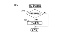
図14は、本発明による第2実施例の停止要求制御を実行するためのルーチンを示している。このルーチンは自動運転制御を行うべきときに繰り返し行われる。図14を参照すると、ステップ201aでは、車両Vの現在位置から一定距離以内で発生した災害に関する災害情報を受信したか否かが判別される。当該災害情報を受信したときには次いでステップ202に進み、車両Vの停止要求が出力される。これに対し、当該災害情報を受信していないときには、車両Vの停止要求を出力することなく、処理サイクルを終了する。
FIG. 14 shows a routine for executing stop request control according to the second embodiment of the present invention. This routine is repeated when automatic operation control is to be performed. Referring to FIG. 14, in
次に、本発明による第3実施例を説明する。以下では、主として、本発明による第1実施例との相違点について説明する。 Next, a third embodiment according to the present invention will be described. In the following, differences from the first embodiment according to the present invention will be mainly described.
図16は本発明による第3実施例の移動体の自動運転制御システムのブロック図を示している。図16を参照すると、本発明による第3実施例の電子制御ユニット10は、ドライバ指示入力部23を備える。ドライバ指示入力部23は、ドライバからの車両停止指示と、車両停止の緊急度とが入力されるように構成されている。すなわち、ドライバが車両Vの自動停止を希望するときには、ドライバはドライバ指示入力部23により、車両停止指示を入力すると共に、車両停止の緊急度を入力する。このために、ドライバ指示入力部23は、例えば、ボタン、ダイヤル、タッチパネル、音声認識装置(マイク)などを備える。なお、本発明による第3実施例では、車両停止の緊急度は、連続的又は段階的に変化する形で入力される。
FIG. 16 shows a block diagram of an automatic driving control system for a moving body according to a third embodiment of the present invention. Referring to FIG. 16, the
本発明による第3実施例でも、状態量代表値があらかじめ定められた設定代表値よりも小さくかつ状態量変化性があらかじめ定められた設定変化性よりも低い第1の領域のうち、状態量代表値が設定代表値よりも大きくかつ状態量変化性が設定変化性よりも低い第2の領域に隣接する領域が、停止適合領域に決定される。本発明による第3実施例では更に、車両停止の緊急度に基づいて設定変化性が設定される。具体的には、車両停止の緊急度が高いときには、車両停止の緊急度が低いときに比べて、設定変化性が高く設定される。このようにすると、車両停止の緊急度が高いときに、車両停止の緊急度が低いときに比べて、上述の第1の領域となる領域の数が増加しうるので、決定される停止適合領域の数が増加しうる。したがって、車両停止の緊急度が高いときに、停止適合領域を比較的容易に見付けることができ、したがって車両Vを比較的速やかに停止させることができる。 Also in the third embodiment according to the present invention, the state quantity representative among the first areas in which the state quantity representative value is smaller than the predetermined set representative value and the state quantity variability is lower than the predetermined set variability. A region adjacent to the second region whose value is larger than the set representative value and whose state quantity variability is lower than the set variability is determined as the stop fit region. In the third embodiment according to the present invention, the setting variability is further set based on the emergency level of the vehicle stop. Specifically, when the emergency level of the vehicle stop is high, the setting changeability is set higher than when the emergency level of the vehicle stop is low. In this case, when the emergency level of the vehicle stop is high, the number of the regions to be the first region described above can be increased compared to when the emergency level of the vehicle stop is low. The number of can increase. Therefore, when the urgent level of the vehicle stop is high, the stop fit region can be found relatively easily, and the vehicle V can be stopped relatively quickly.
すなわち、図16に示される例において、ドライバから車両停止指示及び車両停止の緊急度が入力されると共に、入力された車両停止の緊急度が低いときに、決定された停止適合領域は領域STZのみであるとすると、車両Vが停止適合領域STZに停止するように進路PZが生成される。ドライバから車両停止指示及び車両停止の緊急度が入力されると共に、入力された車両停止の緊急度が中程度のときに、決定された停止適合領域が領域STZ,STYであるとすると、この場合には、車両Vの現在位置から最もに近い停止適合領域STYが選択され、車両Vが停止適合領域STYに停止するように進路PYが生成される。ドライバから車両停止指示及び車両停止の緊急度が入力されると共に、入力された車両停止の緊急度が高いときに、決定された停止適合領域は領域STZ,STY,STXであるとすると、この場合には、車両Vの現在位置から最も近い停止適合領域STXが選択され、車両Vが停止適合領域STXに停止するように進路PXが生成される。このように、ドライバの希望に沿った場所に車両Vが自動的に停止される。 That is, in the example shown in FIG. 16, when the vehicle stop instruction and the emergency level of the vehicle stop are input from the driver and the input emergency level of the vehicle stop is low, the determined stop fit region is only the region STZ. If so, the course PZ is generated so that the vehicle V stops in the stop adaptation region STZ. In this case, if the vehicle stop instruction and the urgency level of the vehicle stop are input from the driver, and the determined stop fit area is the regions STZ and STY when the input urgency level of the vehicle stop is medium The stop adaptation area STY closest to the current position of the vehicle V is selected, and the course PY is generated so that the vehicle V stops in the stop adaptation area STY. In this case, when the vehicle stop instruction and the urgency level of the vehicle stop are input from the driver, and the determined stop adaptation region is the regions STZ, STY, and STX when the input urgency level of the vehicle stop is high The stop adaptation area STX closest to the current position of the vehicle V is selected, and the course PX is generated so that the vehicle V stops in the stop adaptation area STX. In this way, the vehicle V is automatically stopped at a location according to the driver's wishes.
別の実施例(図示しない)では、車両停止の緊急度が低いときには、状態量代表値が設定代表値よりも小さくかつ状態量変化性が比較的低い第1の設定変化性よりも低い領域が第1の領域に設定され、車両停止の緊急度が高いときには、状態量代表値が設定代表値よりも小さくかつ状態量変化性が比較的高い第2の設定変化性よりも低い領域が第1の領域に設定される。 In another embodiment (not shown), when the urgency of the vehicle stop is low, there is a region where the state quantity representative value is smaller than the set representative value and the state quantity variability is lower than the first set variability. When the first region is set and the urgency level of the vehicle stop is high, the region where the state quantity representative value is smaller than the set representative value and the state quantity changeability is relatively high is lower than the second set changeability. Is set in the area.
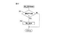
図17は、本発明による第3実施例の停止要求制御を実行するためのルーチンを示している。このルーチンは自動運転制御を行うべきときに繰り返し行われる。図17を参照すると、ステップ201bでは、ドライバから車両停止指示が入力されたか否かが判別される。車両停止指示が入力されたときには次いでステップ202に進み、車両Vの停止要求が出力される。これに対し、車両停止指示が入力されていないときには、車両Vの停止要求を出力することなく、処理サイクルを終了する。
FIG. 17 shows a routine for executing the stop request control of the third embodiment according to the present invention. This routine is repeated when automatic operation control is to be performed. Referring to FIG. 17, in
これまで述べてきた本発明による実施例を互いに組み合せることもできる。一例では、電子制御ユニット10は、ドライバ状態センサ21、災害情報受信部22、及びドライバ指示入力部23のうちの少なくとも2つを備える。
The embodiments according to the invention described so far can also be combined with each other. In one example, the
また、本発明による別の実施例(図示しない)では、本発明による第1実施例又は第2実施例において、車両停止の緊急度に基づいて設定変化性が設定される。具体的には、車両停止の緊急度が高いときには、車両停止の緊急度が低いときに比べて、設定変化性が高く設定される。このようにすると、車両停止の緊急度が高いときに、車両Vを速やかに停止させることができる。 In another embodiment (not shown) according to the present invention, in the first embodiment or the second embodiment according to the present invention, the setting variability is set based on the emergency level of the vehicle stop. Specifically, when the emergency level of the vehicle stop is high, the setting changeability is set higher than when the emergency level of the vehicle stop is low. If it does in this way, when the emergency degree of a vehicle stop is high, the vehicle V can be stopped rapidly.
これまで述べてきた本発明による実施例では、上述したように、車両Vの前後方向の加速度又は減速度が一定の範囲内に維持され、車両Vの横方向の加速度又は減速度が一定の範囲内に維持されるように、停止適合領域が選択される。本発明による別の実施例(図示しない)では、車両停止の緊急度が高いときには、車両停止の緊急度が低いときに比べて、これらの加減速範囲が拡大される。その結果、車両停止の緊急度が高いときには、車両Vをより近い停止適合領域に停止させることが可能となる。 In the embodiments according to the present invention described so far, as described above, the longitudinal acceleration or deceleration of the vehicle V is maintained within a certain range, and the lateral acceleration or deceleration of the vehicle V is within a certain range. The stop fit region is selected to be maintained within. In another embodiment (not shown) according to the present invention, the acceleration / deceleration range is expanded when the emergency level of the vehicle stop is high compared to when the emergency level of the vehicle stop is low. As a result, when the urgency level of the vehicle stop is high, the vehicle V can be stopped in a closer stop adaptation region.
1 外部センサ
6 環境地図記憶装置
10 電子制御ユニット
12 自動運転制御部
12c 進路生成部
13 停止要求判定部
14 停止適合領域決定部
21 ドライバ状態センサ
M 環境地図情報
DESCRIPTION OF SYMBOLS 1
Claims (1)
前記環境地図情報は、
空間内の複数の位置をそれぞれ表す位置情報と、
前記複数の位置のそれぞれの状態量代表値であって、それぞれ対応する前記位置情報と関連付けられた前記状態量代表値と、
前記複数の位置のそれぞれの状態量変化性であって、それぞれ対応する前記位置情報と関連付けられた前記状態量変化性と、
を有しており、前記状態量変化性は、対応する位置の状態量の時間に対する変化のしやすさを表しており、
前記電子制御ユニットは、
前記環境地図情報の前記状態量代表値及び前記状態量変化性に基づいて、前記移動体が停止するのに適した停止適合領域を決定するように構成されている停止適合領域決定部
を備える、移動体の自動運転制御システム。 An automatic driving control system for a moving body comprising an environmental map storage device storing environmental map information and an electronic control unit,
The environmental map information is
Position information representing each of a plurality of positions in space;
A state quantity representative value of each of the plurality of positions, the state quantity representative value associated with the corresponding position information, and
State quantity variability of each of the plurality of positions, the state quantity variability associated with the corresponding position information, and
The state quantity variability represents the ease of change of the state quantity at the corresponding position with respect to time,
The electronic control unit is
A stop adaptation area determination unit configured to determine a stop adaptation area suitable for the mobile body to stop based on the state quantity representative value of the environment map information and the state quantity variability; Automatic operation control system for moving objects.
Priority Applications (1)
| Application Number | Priority Date | Filing Date | Title |
|---|---|---|---|
| JP2016086494A JP6668915B2 (en) | 2016-04-22 | 2016-04-22 | Automatic operation control system for moving objects |
Applications Claiming Priority (1)
| Application Number | Priority Date | Filing Date | Title |
|---|---|---|---|
| JP2016086494A JP6668915B2 (en) | 2016-04-22 | 2016-04-22 | Automatic operation control system for moving objects |
Publications (2)
| Publication Number | Publication Date |
|---|---|
| JP2017194930A true JP2017194930A (en) | 2017-10-26 |
| JP6668915B2 JP6668915B2 (en) | 2020-03-18 |
Family
ID=60155992
Family Applications (1)
| Application Number | Title | Priority Date | Filing Date |
|---|---|---|---|
| JP2016086494A Active JP6668915B2 (en) | 2016-04-22 | 2016-04-22 | Automatic operation control system for moving objects |
Country Status (1)
| Country | Link |
|---|---|
| JP (1) | JP6668915B2 (en) |
Cited By (2)
| Publication number | Priority date | Publication date | Assignee | Title |
|---|---|---|---|---|
| JPWO2021059437A1 (en) * | 2019-09-26 | 2021-04-01 | ||
| US11370437B2 (en) | 2019-01-15 | 2022-06-28 | Toyota Jidosha Kabushiki Kaisha | Vehicle control device and vehicle control method |
Citations (3)
| Publication number | Priority date | Publication date | Assignee | Title |
|---|---|---|---|---|
| JP2014219723A (en) * | 2013-05-01 | 2014-11-20 | 村田機械株式会社 | Autonomous mobile body |
| WO2015072002A1 (en) * | 2013-11-15 | 2015-05-21 | 株式会社日立製作所 | Mobile robot system |
| JP2016038689A (en) * | 2014-08-07 | 2016-03-22 | 日立オートモティブシステムズ株式会社 | Action plan device |
-
2016
- 2016-04-22 JP JP2016086494A patent/JP6668915B2/en active Active
Patent Citations (3)
| Publication number | Priority date | Publication date | Assignee | Title |
|---|---|---|---|---|
| JP2014219723A (en) * | 2013-05-01 | 2014-11-20 | 村田機械株式会社 | Autonomous mobile body |
| WO2015072002A1 (en) * | 2013-11-15 | 2015-05-21 | 株式会社日立製作所 | Mobile robot system |
| JP2016038689A (en) * | 2014-08-07 | 2016-03-22 | 日立オートモティブシステムズ株式会社 | Action plan device |
Cited By (5)
| Publication number | Priority date | Publication date | Assignee | Title |
|---|---|---|---|---|
| US11370437B2 (en) | 2019-01-15 | 2022-06-28 | Toyota Jidosha Kabushiki Kaisha | Vehicle control device and vehicle control method |
| JPWO2021059437A1 (en) * | 2019-09-26 | 2021-04-01 | ||
| WO2021059437A1 (en) * | 2019-09-26 | 2021-04-01 | ヤマハ発動機株式会社 | Environment map creation device and method, local position estimation device, and autonomous moving body |
| US20220276659A1 (en) * | 2019-09-26 | 2022-09-01 | Yamaha Hatsudoki Kabushiki Kaisha | Environment map creation device and method, local position estimation device, and autonomous moving body |
| JP7214881B2 (en) | 2019-09-26 | 2023-01-30 | ヤマハ発動機株式会社 | Environmental mapping device and method, self-localization device, autonomous mobile body |
Also Published As
| Publication number | Publication date |
|---|---|
| JP6668915B2 (en) | 2020-03-18 |
Similar Documents
| Publication | Publication Date | Title |
|---|---|---|
| US10331139B2 (en) | Navigation device for autonomously driving vehicle | |
| JP6544320B2 (en) | Control system and control method of autonomous driving vehicle | |
| EP3324556A1 (en) | Visual communication system for autonomous driving vehicles (adv) | |
| EP3075618A2 (en) | Vehicle control apparatus | |
| RU2760046C1 (en) | Driving assistance and driving assistance device | |
| JP6508114B2 (en) | Automatic operation control system of moving object | |
| CN109720343B (en) | Vehicle control apparatus | |
| JP6252399B2 (en) | Lane change support device | |
| JP6512194B2 (en) | Control system and control method of autonomous driving vehicle | |
| JP7163729B2 (en) | vehicle controller | |
| JP2019197467A (en) | Vehicle control device | |
| CN111724627A (en) | Automatic warning system for detecting backward sliding of front vehicle | |
| KR20210037791A (en) | Autonomous driving apparatus and method | |
| WO2021010083A1 (en) | Information processing device, information processing method, and information processing program | |
| JP6705270B2 (en) | Automatic operation control system for mobile | |
| JP6728959B2 (en) | Automatic operation control system for mobile | |
| JP6728970B2 (en) | Automatic operation control system for mobile | |
| JP6668915B2 (en) | Automatic operation control system for moving objects | |
| CN113753072A (en) | Automatic comfort level scoring system based on human driving reference data | |
| JP7147448B2 (en) | map information system | |
| JP6855759B2 (en) | Self-driving vehicle control system | |
| JP6705271B2 (en) | Automatic operation control system for mobile | |
| JP7302311B2 (en) | Vehicle display control device, vehicle display control method, vehicle display control program | |
| KR20200133857A (en) | Autonomous driving apparatus and method | |
| KR20200133850A (en) | Autonomous driving apparatus and method |
Legal Events
| Date | Code | Title | Description |
|---|---|---|---|
| A621 | Written request for application examination |
Free format text: JAPANESE INTERMEDIATE CODE: A621 Effective date: 20181218 |
|
| A977 | Report on retrieval |
Free format text: JAPANESE INTERMEDIATE CODE: A971007 Effective date: 20191030 |
|
| A131 | Notification of reasons for refusal |
Free format text: JAPANESE INTERMEDIATE CODE: A131 Effective date: 20191112 |
|
| A521 | Request for written amendment filed |
Free format text: JAPANESE INTERMEDIATE CODE: A523 Effective date: 20191203 |
|
| TRDD | Decision of grant or rejection written | ||
| A01 | Written decision to grant a patent or to grant a registration (utility model) |
Free format text: JAPANESE INTERMEDIATE CODE: A01 Effective date: 20200128 |
|
| A61 | First payment of annual fees (during grant procedure) |
Free format text: JAPANESE INTERMEDIATE CODE: A61 Effective date: 20200210 |
|
| R151 | Written notification of patent or utility model registration |
Ref document number: 6668915 Country of ref document: JP Free format text: JAPANESE INTERMEDIATE CODE: R151 |