EP3552894A1 - Système d'alimentation en air - Google Patents
Système d'alimentation en air Download PDFInfo
- Publication number
- EP3552894A1 EP3552894A1 EP17877878.3A EP17877878A EP3552894A1 EP 3552894 A1 EP3552894 A1 EP 3552894A1 EP 17877878 A EP17877878 A EP 17877878A EP 3552894 A1 EP3552894 A1 EP 3552894A1
- Authority
- EP
- European Patent Office
- Prior art keywords
- air
- switching circuit
- power line
- supply system
- voltage
- Prior art date
- Legal status (The legal status is an assumption and is not a legal conclusion. Google has not performed a legal analysis and makes no representation as to the accuracy of the status listed.)
- Granted
Links
- 230000005611 electricity Effects 0.000 claims abstract description 18
- 238000011144 upstream manufacturing Methods 0.000 claims abstract description 9
- 230000001172 regenerating effect Effects 0.000 claims description 93
- 230000008929 regeneration Effects 0.000 abstract description 4
- 238000011069 regeneration method Methods 0.000 abstract description 4
- 238000007605 air drying Methods 0.000 description 17
- 102200118606 rs139622189 Human genes 0.000 description 14
- 230000007246 mechanism Effects 0.000 description 13
- 102220631433 Very-long-chain (3R)-3-hydroxyacyl-CoA dehydratase 1_E63A_mutation Human genes 0.000 description 10
- 230000008901 benefit Effects 0.000 description 9
- 230000008030 elimination Effects 0.000 description 7
- 238000003379 elimination reaction Methods 0.000 description 7
- 230000009467 reduction Effects 0.000 description 7
- 102220468813 Peptidyl-tRNA hydrolase ICT1, mitochondrial_E66A_mutation Human genes 0.000 description 6
- 239000002274 desiccant Substances 0.000 description 6
- 238000010586 diagram Methods 0.000 description 6
- 102220631444 Very-long-chain (3R)-3-hydroxyacyl-CoA dehydratase 1_E72A_mutation Human genes 0.000 description 5
- 230000007423 decrease Effects 0.000 description 5
- 238000012423 maintenance Methods 0.000 description 5
- 239000007788 liquid Substances 0.000 description 4
- 230000009471 action Effects 0.000 description 3
- 230000003247 decreasing effect Effects 0.000 description 2
- 238000001914 filtration Methods 0.000 description 2
- VYPSYNLAJGMNEJ-UHFFFAOYSA-N Silicium dioxide Chemical compound O=[Si]=O VYPSYNLAJGMNEJ-UHFFFAOYSA-N 0.000 description 1
- 229910021536 Zeolite Inorganic materials 0.000 description 1
- 230000000903 blocking effect Effects 0.000 description 1
- 238000010276 construction Methods 0.000 description 1
- 230000008878 coupling Effects 0.000 description 1
- 238000010168 coupling process Methods 0.000 description 1
- 238000005859 coupling reaction Methods 0.000 description 1
- HNPSIPDUKPIQMN-UHFFFAOYSA-N dioxosilane;oxo(oxoalumanyloxy)alumane Chemical compound O=[Si]=O.O=[Al]O[Al]=O HNPSIPDUKPIQMN-UHFFFAOYSA-N 0.000 description 1
- 238000001035 drying Methods 0.000 description 1
- 239000000428 dust Substances 0.000 description 1
- 230000000694 effects Effects 0.000 description 1
- JEIPFZHSYJVQDO-UHFFFAOYSA-N iron(III) oxide Inorganic materials O=[Fe]O[Fe]=O JEIPFZHSYJVQDO-UHFFFAOYSA-N 0.000 description 1
- 239000000741 silica gel Substances 0.000 description 1
- 229910002027 silica gel Inorganic materials 0.000 description 1
- 239000010457 zeolite Substances 0.000 description 1
Images


Classifications
-
- B—PERFORMING OPERATIONS; TRANSPORTING
- B60—VEHICLES IN GENERAL
- B60T—VEHICLE BRAKE CONTROL SYSTEMS OR PARTS THEREOF; BRAKE CONTROL SYSTEMS OR PARTS THEREOF, IN GENERAL; ARRANGEMENT OF BRAKING ELEMENTS ON VEHICLES IN GENERAL; PORTABLE DEVICES FOR PREVENTING UNWANTED MOVEMENT OF VEHICLES; VEHICLE MODIFICATIONS TO FACILITATE COOLING OF BRAKES
- B60T17/00—Component parts, details, or accessories of power brake systems not covered by groups B60T8/00, B60T13/00 or B60T15/00, or presenting other characteristic features
- B60T17/002—Air treatment devices
-
- B—PERFORMING OPERATIONS; TRANSPORTING
- B01—PHYSICAL OR CHEMICAL PROCESSES OR APPARATUS IN GENERAL
- B01D—SEPARATION
- B01D53/00—Separation of gases or vapours; Recovering vapours of volatile solvents from gases; Chemical or biological purification of waste gases, e.g. engine exhaust gases, smoke, fumes, flue gases, aerosols
- B01D53/26—Drying gases or vapours
-
- B—PERFORMING OPERATIONS; TRANSPORTING
- B60—VEHICLES IN GENERAL
- B60T—VEHICLE BRAKE CONTROL SYSTEMS OR PARTS THEREOF; BRAKE CONTROL SYSTEMS OR PARTS THEREOF, IN GENERAL; ARRANGEMENT OF BRAKING ELEMENTS ON VEHICLES IN GENERAL; PORTABLE DEVICES FOR PREVENTING UNWANTED MOVEMENT OF VEHICLES; VEHICLE MODIFICATIONS TO FACILITATE COOLING OF BRAKES
- B60T17/00—Component parts, details, or accessories of power brake systems not covered by groups B60T8/00, B60T13/00 or B60T15/00, or presenting other characteristic features
- B60T17/02—Arrangements of pumps or compressors, or control devices therefor
-
- B—PERFORMING OPERATIONS; TRANSPORTING
- B60—VEHICLES IN GENERAL
- B60T—VEHICLE BRAKE CONTROL SYSTEMS OR PARTS THEREOF; BRAKE CONTROL SYSTEMS OR PARTS THEREOF, IN GENERAL; ARRANGEMENT OF BRAKING ELEMENTS ON VEHICLES IN GENERAL; PORTABLE DEVICES FOR PREVENTING UNWANTED MOVEMENT OF VEHICLES; VEHICLE MODIFICATIONS TO FACILITATE COOLING OF BRAKES
- B60T17/00—Component parts, details, or accessories of power brake systems not covered by groups B60T8/00, B60T13/00 or B60T15/00, or presenting other characteristic features
- B60T17/04—Arrangements of piping, valves in the piping, e.g. cut-off valves, couplings or air hoses
-
- B—PERFORMING OPERATIONS; TRANSPORTING
- B60—VEHICLES IN GENERAL
- B60T—VEHICLE BRAKE CONTROL SYSTEMS OR PARTS THEREOF; BRAKE CONTROL SYSTEMS OR PARTS THEREOF, IN GENERAL; ARRANGEMENT OF BRAKING ELEMENTS ON VEHICLES IN GENERAL; PORTABLE DEVICES FOR PREVENTING UNWANTED MOVEMENT OF VEHICLES; VEHICLE MODIFICATIONS TO FACILITATE COOLING OF BRAKES
- B60T17/00—Component parts, details, or accessories of power brake systems not covered by groups B60T8/00, B60T13/00 or B60T15/00, or presenting other characteristic features
- B60T17/18—Safety devices; Monitoring
- B60T17/22—Devices for monitoring or checking brake systems; Signal devices
- B60T17/221—Procedure or apparatus for checking or keeping in a correct functioning condition of brake systems
Definitions
- the functionality of the dehumidifying action of the air dryer decreases. For this reason, the regenerative operation is performed to recover the decrease in the functionality of the dehumidifying action.
- a command from the ECU can cause the regenerative operation to be performed.
- weather-resistant wires and connectors need to be arranged between the ECU and the air dryer.
- the power lines connected to the governor device, which operates the discharge device is shared with the second pneumatic sensor.
- increases in the number of wires and connectors are prevented or limited in the power lines.
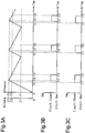
- Fig. 1 shows a first embodiment in which an air supply system 10 is applied to a brake system of an articulated vehicle.
- the brake system has parking brakes and service brakes serving as brakes using compressed dry air to drive the brakes.
- the articulated vehicle is a vehicle in which a trailer is connected to a tractor.
- the tractor 1 includes an engine 3, a compressor 4, and the air supply system 10.
- the compressor 4 is driven by the power of the engine 3.
- the air supply system 10 dries and cleans compressed air supplied from the compressor 4 and supplies the air to the service brake circuit and the park brake circuit.
- a trailer control valve (TCV) 8 incorporated in a second service brake circuit and a second parking brake circuit is connected to a predetermined port of the air supply system 10.
- the trailer control valve 8 controls supply and discharge of air to and from the pneumatic circuits of the trailer 2, thereby actuating and releasing the service brakes and the parking brakes of the trailer 2.
- the compressor 4 is switched between an actuated state (load state), in which air is compressed and supplied, and a de-actuated state (unload state), in which air is not compressed.
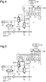
- the supply circuit 12 is connected to the ECU 80 and supplies air delivered from the air drying circuit 11 to a first load C21 to an eighth load C28, which are installed in the vehicle.
- the supply circuit 12 is provided with a first port P21 to an eighth port P28 respectively connected to the first load C21 to the eighth load C28.
- the air supply system 10 includes a maintenance port P12.
- the maintenance port P12 is a port for supplying air to the air drying circuit 11 during maintenance.
- the fourth load C24, which is connected to the fourth port P24, and the sixth load C26, which is connected to the sixth port P26, are accessory circuits that activate or deactivate accessories.
- the seventh load C27, which is connected to the seventh port P27, is an inflator for tires using compressed air.
- the eighth load C28, which is connected to the eighth port P28, is a circuit of an air tank that stores compressed air.
- the air drying circuit 11 includes an air supply passage 18.
- a first passage 41 to a fifth passage 45 that supply air to each load are connected from the air supply passage 18.
- the second passage 42 and the third passage 43 are passages through which air is supplied respectively to the first load C21 and the second load C22, which are service brake circuits. Further, the second passage 42 and the third passage 43 are connected to the fourth passage 44. Air is supplied through the fourth passage 44 to the third load C23 and the fifth load C25, which are parking brake circuits, and the fourth load C24 and the sixth load C26, which are accessory circuits.
- the fourth passage 44 is provided with a check valve 66 that permits the flow of air from the second passage 42 and a check valve 67 that permits the flow of air from the third passage 43.
- the fifth passage 45 allows the passage of air from a ninth passage 49, which is connected to the third load C23, and is provided with a check valve 45A in the middle of the fifth passage 45.
- the check valve 45A permits the flow of air from the ninth passage 49 and prohibits the flow of air from the air supply passage 18 to each load. Further, a passage through which air is supplied to the seventh load C27 and a passage through which air is supplied to the eighth load C28 branch from the air supply passage 18 of the air drying circuit 11.
- the air drying circuit 11 includes a filter 17 serving as a removal device.
- the filter 17 is located in the middle of the air supply passage 18, which connects the compressor 4 to the supply circuit 12.
- the filter 17 includes desiccant for trapping moisture and a filter portion for trapping oil.
- the filter 17 causes air to pass through the desiccant, thereby removing moisture contained in the air and drying the air. Further, the filter 17 removes oil contained in the air and cleans the air using the filter portion.
- the air that has passed through the filter 17 is supplied to the supply circuit 12 via a check valve 19 serving as a non-return valve that permits the flow of air only toward the downstream side as viewed from the filter 17. That is, when a portion including the filter 17 is referred to as the upstream side and a portion including the supply circuit 12 is referred to as the downstream side, the check valve 19 permits the flow of air only from the upstream side to the downstream side.
- the switching circuit 120 outputs a power line E63A, which controls connection and disconnection with the power line E63, and allows the power line E63A to be connected to the regenerative control valve 21.
- the switching circuit 120 receives voltage corresponding to the air pressure of the supply circuit 12 from the signal line E62.
- the switching circuit 120 operates the regenerative control valve 21 to open the bypass passage 20 by closing the section between the power line E63 and the power line E63A.
- the switching circuit 120 opens the section between the power line E63 and the power line E63A to stop the operation of the regenerative control valve 21, thereby blocking the bypass passage 20.
- the signal line E62 of the pneumatic sensor 111 only needs to be branched and connected to the switching circuit 120. This allows the pneumatic sensor 111 and the switching circuit 120 to be arranged close to each other. Thus, the distances between wires can be shortened.
- the air pressure thereof increases.
- the air pressure increases until it exceeds the pressure P3 (timing t11) and reaches the pressure P2 (timing t12), thereby the compressor 4 is de-actuated.
- the air pressure gradually decreases as compressed air is used.
- the air pressure of the supply circuit 12 reaches the pressure P1
- the compressor 4 is re-actuated.
- the compressor 4 is de-actuated again.
- the regenerative operation is performed when the air pressure of the supply circuit 12 is between the pressure P2 (timing t12) and the pressure P3 (timing t13). That is, when detecting the voltage E2 corresponding to the pressure P2 (timing t12), the switching circuit 120 closes the section between the power line E63 and the power line E63A. Thus, the regenerative control valve 21 operates to open the bypass passage 20, thereby starting the regenerative operation. Subsequently, when the air pressure decreases and the switching circuit 120 detects the voltage E3 corresponding to the pressure P3 (timing t13), the switching circuit 120 opens the section between the power line E63 and the power line E63A.
- the switching circuit 120 is an electronic circuit that includes a switching mechanism such as a relay.
- the voltage E2, which is a threshold value at which the circuit is closed, and the voltage E3, which is a threshold value at which the circuit is opened, are set within the switching circuit 120 in advance. Additionally, when the regenerative control valve 21 performs the regenerative operation, the operation pressure of a governor 26 is set in advance such that the governor 26 is located at an intake position.
- the regenerative operation is performed while the air pressure of the supply circuit 12 is greater than or equal to the pressure P3 (between timing t11 and timing t13). That is, when detecting the voltage greater than or equal to the voltage E3 corresponding to the pressure P3 (timing t11), the switching circuit 120 closes the section between the power line E63 and the power line E63A. Thus, the regenerative control valve 21 operates to open the bypass passage 20, thereby starting the regenerative operation. Since the compressor 4 is actuated, the air pressure continues to increase. Then, the compressor 4 is de-actuated with the pressure P2 (timing t12).
- the drain valve 25 is kept at the closed position in a state in which a pneumatic signal is not received by the port, that is, in a state in which air is not supplied.
- the drain valve 25 is moved to the open position when receiving a pneumatic signal. Further, when the pressure of the input port corresponding to the compressor 4 of the drain valve 25 exceeds an upper limit value to become high, the drain valve 25 is forcibly switched to the open position.
- the drain valve 25 is also opened by a test signal of the compressed air received through the maintenance port P12.
- the present embodiment has the following advantages.
- a ground line E67 and a power line E68 of a connector CN2 and the signal line E62, which outputs voltage corresponding to an air pressure output by the pneumatic sensor 111, are connected to the switching circuit 120.
- the switching circuit 120 controls opening and closing of the section between the power line E68 and a power line E68A and connects the power line E68A to the regenerative control valve 21.
- the switching circuit 120 receives the voltage corresponding to the air pressure of the supply circuit 12 from the signal line E62.
- the switching circuit 120 closes the section between the power line E68 and the power line E68A to open the bypass passage 20.
- the switching circuit 120 opens the section between the power line E68 and the power line E68A to block the bypass passage 20.
- the air supply system includes the governor 26A, which serves as a governor device, and a switching circuit 121 (SW), which has the same configuration as the switching circuit 120.
- the governor 26A which serves as a governor device
- SW switching circuit 121
- the governor 26A is a solenoid valve that functions differently when powered on and off.
- the ground line E64 and a power line E66A are connected to the governor 26A.
- the operations of the governor 26A are controlled by being powered on and off when the switching circuit 121 opens and closes the section between the power line E66 and the power line E66A.
- the switching circuit 120 opens the section between the power line E63 and the power line E63A to set the governor 26A at the exhaust position. This causes the governor 26A to supply a pneumatic signal to the compressor 4 and the drain valve 25.
- the drain valve 25 opens when receiving the pneumatic signal from the governor 26A.
- the regenerative control valve 21 and the governor 26A are both solenoid valves.
- the ground line E67 and the power line E68 of the connector CN2 and the signal line E62, which outputs the voltage corresponding to the air pressure output by the pneumatic sensor 111, are connected to the switching circuit 120. Further, the switching circuit 120 controls opening and closing of the section between the power line E68 and the power line E68A and connects the power line E68A to the humidity sensor 122.
- the bypass passage 20 opens.
- the bypass passage 20 is blocked so that the regenerative operation is not performed.
- the present embodiment has the following advantage in addition to advantages (1) to (3), (5), and (6) of the first and second embodiments.
- (9) When the humidity of air is high, a large amount of moisture is dehumidified and thus the regenerative operation needs to be performed. In contrast, when the humidity of air is low, a small amount of moisture is dehumidified and thus the regenerative operation does not need to be performed.
- the humidity is a predetermined humidity
- the regenerative control valve 21 is supplied with power to execute the regenerative operation.
- the regenerative control valve 21 is not supplied with power and the regenerative operation is not executed. This prevents compressed air from being consumed through the regenerative operation.
- the pressure switch 123 closes the section between the power line E72 and the power line E72A to operate the regenerative control valve 21 and open the bypass passage 20. In other voltages, the pressure switch 123 opens the section between the power line E72 and the power line E72A to stop the regenerative control valve 21 and block the bypass passage 20.
- the switching circuit 120 receives the voltage corresponding to the air pressure of the supply circuit 12 from the pneumatic sensor 111. Instead, the switching circuit may receive the voltage corresponding to the air pressure of the supply circuit 12 from another pneumatic sensor.
- the filter 17 includes desiccant and the filtering portion. Instead, the filter 17 may include only one of desiccant and the filtering portion.
- the air supply system 10 is mounted in the articulated vehicle including the tractor 1 and the trailer 2.
- the air supply system may be mounted in other vehicles such as passenger cars, railway vehicles, and the like.
Applications Claiming Priority (2)
| Application Number | Priority Date | Filing Date | Title |
|---|---|---|---|
| JP2016238362 | 2016-12-08 | ||
| PCT/JP2017/044100 WO2018105711A1 (fr) | 2016-12-08 | 2017-12-07 | Système d'alimentation en air |
Publications (3)
| Publication Number | Publication Date |
|---|---|
| EP3552894A1 true EP3552894A1 (fr) | 2019-10-16 |
| EP3552894A4 EP3552894A4 (fr) | 2020-07-08 |
| EP3552894B1 EP3552894B1 (fr) | 2023-02-08 |
Family
ID=62492006
Family Applications (1)
| Application Number | Title | Priority Date | Filing Date |
|---|---|---|---|
| EP17877878.3A Active EP3552894B1 (fr) | 2016-12-08 | 2017-12-07 | Système d'alimentation en air |
Country Status (3)
| Country | Link |
|---|---|
| EP (1) | EP3552894B1 (fr) |
| JP (3) | JP7099962B2 (fr) |
| WO (1) | WO2018105711A1 (fr) |
Cited By (1)
| Publication number | Priority date | Publication date | Assignee | Title |
|---|---|---|---|---|
| EP4183646A1 (fr) * | 2021-11-17 | 2023-05-24 | ALSTOM Transport Technologies | Système et procédé de gestion d'alimentation d'air pour un équipement comprenant un système pneumatique et système pneumatique et équipement associés, en particulier un véhicule de transport |
Families Citing this family (9)
| Publication number | Priority date | Publication date | Assignee | Title |
|---|---|---|---|---|
| CN116985775A (zh) * | 2018-12-28 | 2023-11-03 | 纳博特斯克汽车零部件有限公司 | 空气供给系统 |
| WO2020175467A1 (fr) * | 2019-02-25 | 2020-09-03 | ナブテスコオートモーティブ株式会社 | Système d'alimentation en air, procédé de commande pour système d'alimentation en air et programme de commande pour système d'alimentation en air |
| DE102019104760A1 (de) * | 2019-02-25 | 2020-08-27 | Knorr-Bremse Systeme für Schienenfahrzeuge GmbH | Luftversorgungsanlage und Verfahren zum Steuern und/oder Überwachen einer Luftversorgungsanlage |
| JPWO2020175466A1 (ja) * | 2019-02-25 | 2021-12-23 | ナブテスコオートモーティブ株式会社 | 空気供給システム、空気供給システムの制御方法、及び空気供給システムの制御プログラム |
| CN113766963A (zh) * | 2019-02-25 | 2021-12-07 | 纳博特斯克汽车零部件有限公司 | 空气供给系统、空气供给系统的控制方法及空气供给系统的控制程序 |
| EP4265922A1 (fr) | 2020-12-18 | 2023-10-25 | Semyungtech Co., Ltd. | Dispositif de traitement d'air comprimé pour véhicule utilitaire |
| KR102248427B1 (ko) * | 2020-12-18 | 2021-05-07 | 주식회사 세명테크 | 상용차용 압축 공기 처리 장치 |
| EP4265923A1 (fr) | 2020-12-18 | 2023-10-25 | Semyungtech Co., Ltd. | Système de traitement d'air comprimé pour véhicule utilitaire |
| KR102248426B1 (ko) * | 2020-12-18 | 2021-05-07 | 주식회사 세명테크 | 상용차용 압축 공기 처리 장치 |
Family Cites Families (16)
| Publication number | Priority date | Publication date | Assignee | Title |
|---|---|---|---|---|
| DE19515895A1 (de) * | 1995-04-29 | 1996-10-31 | Bosch Gmbh Robert | Druckluft-Versorgungseinrichtung für Fahrzeug-Druckluftanlagen sowie Verfahren zum Steuern der Druckluft-Versorgungseinrichtung |
| JP3322337B2 (ja) | 1997-04-28 | 2002-09-09 | 株式会社ナブコ | エアドライヤ |
| GB0023350D0 (en) * | 2000-09-22 | 2000-11-08 | Wabco Automotive Uk Ltd | Vehicle air braking system |
| DE102006023681B4 (de) * | 2006-05-19 | 2009-07-02 | Knorr-Bremse Systeme für Nutzfahrzeuge GmbH | Verfahren zum Steuern beziehungsweise Regeln des Luftdrucks in einer Druckluftversorgungseinrichtung |
| JP2007326516A (ja) | 2006-06-09 | 2007-12-20 | Nissan Motor Co Ltd | 電動パーキングブレーキ装置 |
| DE102006048071A1 (de) * | 2006-10-11 | 2008-04-17 | Wabco Gmbh | Druckluftversorgungsanlage und Verfahren zur Parameter-Ermittlung der Anlage |
| JP5278888B2 (ja) * | 2007-05-10 | 2013-09-04 | ナブテスコオートモーティブ株式会社 | エアドライヤおよび圧縮空気供給システム |
| DE102009003396A1 (de) * | 2009-01-28 | 2010-07-29 | Continental Aktiengesellschaft | Verfahren zum Steuern der Regenerationszyklen für einen Lufttrockner in einer geschlossenen Niveauregelanlage für Fahrzeuge |
| JP5410802B2 (ja) * | 2009-03-25 | 2014-02-05 | ナブテスコオートモーティブ株式会社 | 車両用圧縮空気供給装置、及び、車両用圧縮空気供給装置の制御方法 |
| JP5497357B2 (ja) * | 2009-07-24 | 2014-05-21 | ナブテスコオートモーティブ株式会社 | 車両用圧縮空気供給装置 |
| JP5762754B2 (ja) * | 2011-01-05 | 2015-08-12 | ナブテスコオートモーティブ株式会社 | 車両用圧縮空気供給装置 |
| WO2012067215A2 (fr) * | 2010-11-15 | 2012-05-24 | ナブテスコオートモーティブ株式会社 | Silencieux, soupape d'évacuation, dispositif soupape, sécheur d'air, dispositif d'alimentation en air comprimé pour un véhicule et système d'alimentation en air comprimé |
| DE102013003513A1 (de) | 2013-03-04 | 2014-09-04 | Wabco Gmbh | Verdichteranordnung zum Betreiben einer Druckluftversorgungsanlage, Druckluftversorgungsanlage und Druckluftversorgungssystem sowie Fahrzeug mit einer solchen Druckluftversorgungsanlage |
| JP5830514B2 (ja) * | 2013-11-07 | 2015-12-09 | ナブテスコオートモーティブ株式会社 | 車両用空気圧縮供給装置、車両用空気圧縮供給システム、及び、車両用空気圧縮供給装置の制御方法 |
| JP6231863B2 (ja) * | 2013-11-29 | 2017-11-15 | 日立オートモティブシステムズ株式会社 | エアサスペンションシステム |
| US10434464B2 (en) * | 2014-05-09 | 2019-10-08 | Nabtesco Automotive Corporation | Compressed-air drying device, method for controlling compressed-air drying device, and vehicle |
-
2017
- 2017-12-07 WO PCT/JP2017/044100 patent/WO2018105711A1/fr unknown
- 2017-12-07 JP JP2018555069A patent/JP7099962B2/ja active Active
- 2017-12-07 EP EP17877878.3A patent/EP3552894B1/fr active Active
-
2022
- 2022-04-28 JP JP2022074952A patent/JP7273222B2/ja active Active
-
2023
- 2023-04-26 JP JP2023072203A patent/JP7464775B2/ja active Active
Cited By (1)
| Publication number | Priority date | Publication date | Assignee | Title |
|---|---|---|---|---|
| EP4183646A1 (fr) * | 2021-11-17 | 2023-05-24 | ALSTOM Transport Technologies | Système et procédé de gestion d'alimentation d'air pour un équipement comprenant un système pneumatique et système pneumatique et équipement associés, en particulier un véhicule de transport |
Also Published As
| Publication number | Publication date |
|---|---|
| JPWO2018105711A1 (ja) | 2019-10-24 |
| JP2023090822A (ja) | 2023-06-29 |
| JP7273222B2 (ja) | 2023-05-12 |
| EP3552894A4 (fr) | 2020-07-08 |
| WO2018105711A1 (fr) | 2018-06-14 |
| EP3552894B1 (fr) | 2023-02-08 |
| JP7099962B2 (ja) | 2022-07-12 |
| JP7464775B2 (ja) | 2024-04-09 |
| JP2022109286A (ja) | 2022-07-27 |
Similar Documents
| Publication | Publication Date | Title |
|---|---|---|
| EP3552894B1 (fr) | Système d'alimentation en air | |
| JP5762754B2 (ja) | 車両用圧縮空気供給装置 | |
| JP5187664B2 (ja) | 車両用圧縮空気供給システムおよびエアドライヤ | |
| JP7269004B2 (ja) | 空気供給システム | |
| JP6767125B2 (ja) | 空気供給システム | |
| CN107206992B (zh) | 用于给商用车供给压缩空气的设备和方法 | |
| JP2023059903A (ja) | 空気供給システム | |
| JP7439179B2 (ja) | 空気供給回路 | |
| CN113766965B (zh) | 空气供给系统、空气供给系统的控制方法及空气供给系统的控制程序 | |
| CN113613757B (zh) | 空气供给系统 | |
| JP7263049B2 (ja) | 空気供給システム及び空気供給システムの制御方法 | |
| JP6727226B2 (ja) | 空気供給システム及び空気供給システムの制御方法 | |
| JP7483672B2 (ja) | 空気供給システム、空気供給システムの制御方法、及び空気供給システムの制御プログラム | |
| JP7226992B2 (ja) | 空気供給システム | |
| CN113613758B (zh) | 空气供给系统 | |
| JP7420740B2 (ja) | 空気供給システム | |
| WO2020175465A1 (fr) | Système d'alimentation en air, procédé de commande pour système d'alimentation en air et programme de commande pour système d'alimentation en air |
Legal Events
| Date | Code | Title | Description |
|---|---|---|---|
| STAA | Information on the status of an ep patent application or granted ep patent |
Free format text: STATUS: THE INTERNATIONAL PUBLICATION HAS BEEN MADE |
|
| PUAI | Public reference made under article 153(3) epc to a published international application that has entered the european phase |
Free format text: ORIGINAL CODE: 0009012 |
|
| STAA | Information on the status of an ep patent application or granted ep patent |
Free format text: STATUS: REQUEST FOR EXAMINATION WAS MADE |
|
| 17P | Request for examination filed |
Effective date: 20190702 |
|
| AK | Designated contracting states |
Kind code of ref document: A1 Designated state(s): AL AT BE BG CH CY CZ DE DK EE ES FI FR GB GR HR HU IE IS IT LI LT LU LV MC MK MT NL NO PL PT RO RS SE SI SK SM TR |
|
| AX | Request for extension of the european patent |
Extension state: BA ME |
|
| DAV | Request for validation of the european patent (deleted) | ||
| DAX | Request for extension of the european patent (deleted) | ||
| A4 | Supplementary search report drawn up and despatched |
Effective date: 20200609 |
|
| RIC1 | Information provided on ipc code assigned before grant |
Ipc: B60T 17/00 20060101AFI20200604BHEP Ipc: B01D 53/26 20060101ALI20200604BHEP |
|
| GRAP | Despatch of communication of intention to grant a patent |
Free format text: ORIGINAL CODE: EPIDOSNIGR1 |
|
| STAA | Information on the status of an ep patent application or granted ep patent |
Free format text: STATUS: GRANT OF PATENT IS INTENDED |
|
| INTG | Intention to grant announced |
Effective date: 20220629 |
|
| GRAS | Grant fee paid |
Free format text: ORIGINAL CODE: EPIDOSNIGR3 |
|
| GRAA | (expected) grant |
Free format text: ORIGINAL CODE: 0009210 |
|
| STAA | Information on the status of an ep patent application or granted ep patent |
Free format text: STATUS: THE PATENT HAS BEEN GRANTED |
|
| AK | Designated contracting states |
Kind code of ref document: B1 Designated state(s): AL AT BE BG CH CY CZ DE DK EE ES FI FR GB GR HR HU IE IS IT LI LT LU LV MC MK MT NL NO PL PT RO RS SE SI SK SM TR |
|
| REG | Reference to a national code |
Ref country code: GB Ref legal event code: FG4D |
|
| REG | Reference to a national code |
Ref country code: CH Ref legal event code: EP Ref country code: AT Ref legal event code: REF Ref document number: 1547407 Country of ref document: AT Kind code of ref document: T Effective date: 20230215 |
|
| REG | Reference to a national code |
Ref country code: IE Ref legal event code: FG4D |
|
| REG | Reference to a national code |
Ref country code: DE Ref legal event code: R096 Ref document number: 602017065974 Country of ref document: DE |
|
| REG | Reference to a national code |
Ref country code: LT Ref legal event code: MG9D |
|
| REG | Reference to a national code |
Ref country code: NL Ref legal event code: MP Effective date: 20230208 |
|
| REG | Reference to a national code |
Ref country code: AT Ref legal event code: MK05 Ref document number: 1547407 Country of ref document: AT Kind code of ref document: T Effective date: 20230208 |
|
| PG25 | Lapsed in a contracting state [announced via postgrant information from national office to epo] |
Ref country code: RS Free format text: LAPSE BECAUSE OF FAILURE TO SUBMIT A TRANSLATION OF THE DESCRIPTION OR TO PAY THE FEE WITHIN THE PRESCRIBED TIME-LIMIT Effective date: 20230208 Ref country code: PT Free format text: LAPSE BECAUSE OF FAILURE TO SUBMIT A TRANSLATION OF THE DESCRIPTION OR TO PAY THE FEE WITHIN THE PRESCRIBED TIME-LIMIT Effective date: 20230609 Ref country code: NO Free format text: LAPSE BECAUSE OF FAILURE TO SUBMIT A TRANSLATION OF THE DESCRIPTION OR TO PAY THE FEE WITHIN THE PRESCRIBED TIME-LIMIT Effective date: 20230508 Ref country code: NL Free format text: LAPSE BECAUSE OF FAILURE TO SUBMIT A TRANSLATION OF THE DESCRIPTION OR TO PAY THE FEE WITHIN THE PRESCRIBED TIME-LIMIT Effective date: 20230208 Ref country code: LV Free format text: LAPSE BECAUSE OF FAILURE TO SUBMIT A TRANSLATION OF THE DESCRIPTION OR TO PAY THE FEE WITHIN THE PRESCRIBED TIME-LIMIT Effective date: 20230208 Ref country code: LT Free format text: LAPSE BECAUSE OF FAILURE TO SUBMIT A TRANSLATION OF THE DESCRIPTION OR TO PAY THE FEE WITHIN THE PRESCRIBED TIME-LIMIT Effective date: 20230208 Ref country code: HR Free format text: LAPSE BECAUSE OF FAILURE TO SUBMIT A TRANSLATION OF THE DESCRIPTION OR TO PAY THE FEE WITHIN THE PRESCRIBED TIME-LIMIT Effective date: 20230208 Ref country code: ES Free format text: LAPSE BECAUSE OF FAILURE TO SUBMIT A TRANSLATION OF THE DESCRIPTION OR TO PAY THE FEE WITHIN THE PRESCRIBED TIME-LIMIT Effective date: 20230208 Ref country code: AT Free format text: LAPSE BECAUSE OF FAILURE TO SUBMIT A TRANSLATION OF THE DESCRIPTION OR TO PAY THE FEE WITHIN THE PRESCRIBED TIME-LIMIT Effective date: 20230208 |
|
| PG25 | Lapsed in a contracting state [announced via postgrant information from national office to epo] |
Ref country code: SE Free format text: LAPSE BECAUSE OF FAILURE TO SUBMIT A TRANSLATION OF THE DESCRIPTION OR TO PAY THE FEE WITHIN THE PRESCRIBED TIME-LIMIT Effective date: 20230208 Ref country code: PL Free format text: LAPSE BECAUSE OF FAILURE TO SUBMIT A TRANSLATION OF THE DESCRIPTION OR TO PAY THE FEE WITHIN THE PRESCRIBED TIME-LIMIT Effective date: 20230208 Ref country code: IS Free format text: LAPSE BECAUSE OF FAILURE TO SUBMIT A TRANSLATION OF THE DESCRIPTION OR TO PAY THE FEE WITHIN THE PRESCRIBED TIME-LIMIT Effective date: 20230608 Ref country code: GR Free format text: LAPSE BECAUSE OF FAILURE TO SUBMIT A TRANSLATION OF THE DESCRIPTION OR TO PAY THE FEE WITHIN THE PRESCRIBED TIME-LIMIT Effective date: 20230509 Ref country code: FI Free format text: LAPSE BECAUSE OF FAILURE TO SUBMIT A TRANSLATION OF THE DESCRIPTION OR TO PAY THE FEE WITHIN THE PRESCRIBED TIME-LIMIT Effective date: 20230208 |
|
| PG25 | Lapsed in a contracting state [announced via postgrant information from national office to epo] |
Ref country code: SM Free format text: LAPSE BECAUSE OF FAILURE TO SUBMIT A TRANSLATION OF THE DESCRIPTION OR TO PAY THE FEE WITHIN THE PRESCRIBED TIME-LIMIT Effective date: 20230208 Ref country code: RO Free format text: LAPSE BECAUSE OF FAILURE TO SUBMIT A TRANSLATION OF THE DESCRIPTION OR TO PAY THE FEE WITHIN THE PRESCRIBED TIME-LIMIT Effective date: 20230208 Ref country code: EE Free format text: LAPSE BECAUSE OF FAILURE TO SUBMIT A TRANSLATION OF THE DESCRIPTION OR TO PAY THE FEE WITHIN THE PRESCRIBED TIME-LIMIT Effective date: 20230208 Ref country code: DK Free format text: LAPSE BECAUSE OF FAILURE TO SUBMIT A TRANSLATION OF THE DESCRIPTION OR TO PAY THE FEE WITHIN THE PRESCRIBED TIME-LIMIT Effective date: 20230208 Ref country code: CZ Free format text: LAPSE BECAUSE OF FAILURE TO SUBMIT A TRANSLATION OF THE DESCRIPTION OR TO PAY THE FEE WITHIN THE PRESCRIBED TIME-LIMIT Effective date: 20230208 |
|
| REG | Reference to a national code |
Ref country code: DE Ref legal event code: R097 Ref document number: 602017065974 Country of ref document: DE |
|
| PG25 | Lapsed in a contracting state [announced via postgrant information from national office to epo] |
Ref country code: SK Free format text: LAPSE BECAUSE OF FAILURE TO SUBMIT A TRANSLATION OF THE DESCRIPTION OR TO PAY THE FEE WITHIN THE PRESCRIBED TIME-LIMIT Effective date: 20230208 |
|
| PLBE | No opposition filed within time limit |
Free format text: ORIGINAL CODE: 0009261 |
|
| STAA | Information on the status of an ep patent application or granted ep patent |
Free format text: STATUS: NO OPPOSITION FILED WITHIN TIME LIMIT |
|
| 26N | No opposition filed |
Effective date: 20231109 |
|
| PGFP | Annual fee paid to national office [announced via postgrant information from national office to epo] |
Ref country code: GB Payment date: 20231220 Year of fee payment: 7 |
|
| PG25 | Lapsed in a contracting state [announced via postgrant information from national office to epo] |
Ref country code: SI Free format text: LAPSE BECAUSE OF FAILURE TO SUBMIT A TRANSLATION OF THE DESCRIPTION OR TO PAY THE FEE WITHIN THE PRESCRIBED TIME-LIMIT Effective date: 20230208 |
|
| PGFP | Annual fee paid to national office [announced via postgrant information from national office to epo] |
Ref country code: FR Payment date: 20231222 Year of fee payment: 7 Ref country code: DE Payment date: 20231214 Year of fee payment: 7 |