EP3552877A1 - Fahrzeuglampe - Google Patents
Fahrzeuglampe Download PDFInfo
- Publication number
- EP3552877A1 EP3552877A1 EP19165542.2A EP19165542A EP3552877A1 EP 3552877 A1 EP3552877 A1 EP 3552877A1 EP 19165542 A EP19165542 A EP 19165542A EP 3552877 A1 EP3552877 A1 EP 3552877A1
- Authority
- EP
- European Patent Office
- Prior art keywords
- light source
- source unit
- support point
- support
- bracket
- Prior art date
- Legal status (The legal status is an assumption and is not a legal conclusion. Google has not performed a legal analysis and makes no representation as to the accuracy of the status listed.)
- Withdrawn
Links
Images



Classifications
-
- B—PERFORMING OPERATIONS; TRANSPORTING
- B60—VEHICLES IN GENERAL
- B60Q—ARRANGEMENT OF SIGNALLING OR LIGHTING DEVICES, THE MOUNTING OR SUPPORTING THEREOF OR CIRCUITS THEREFOR, FOR VEHICLES IN GENERAL
- B60Q1/00—Arrangement of optical signalling or lighting devices, the mounting or supporting thereof or circuits therefor
- B60Q1/02—Arrangement of optical signalling or lighting devices, the mounting or supporting thereof or circuits therefor the devices being primarily intended to illuminate the way ahead or to illuminate other areas of way or environments
- B60Q1/04—Arrangement of optical signalling or lighting devices, the mounting or supporting thereof or circuits therefor the devices being primarily intended to illuminate the way ahead or to illuminate other areas of way or environments the devices being headlights
- B60Q1/06—Arrangement of optical signalling or lighting devices, the mounting or supporting thereof or circuits therefor the devices being primarily intended to illuminate the way ahead or to illuminate other areas of way or environments the devices being headlights adjustable, e.g. remotely-controlled from inside vehicle
- B60Q1/076—Arrangement of optical signalling or lighting devices, the mounting or supporting thereof or circuits therefor the devices being primarily intended to illuminate the way ahead or to illuminate other areas of way or environments the devices being headlights adjustable, e.g. remotely-controlled from inside vehicle by electrical means including means to transmit the movements, e.g. shafts or joints
-
- B—PERFORMING OPERATIONS; TRANSPORTING
- B60—VEHICLES IN GENERAL
- B60Q—ARRANGEMENT OF SIGNALLING OR LIGHTING DEVICES, THE MOUNTING OR SUPPORTING THEREOF OR CIRCUITS THEREFOR, FOR VEHICLES IN GENERAL
- B60Q1/00—Arrangement of optical signalling or lighting devices, the mounting or supporting thereof or circuits therefor
- B60Q1/02—Arrangement of optical signalling or lighting devices, the mounting or supporting thereof or circuits therefor the devices being primarily intended to illuminate the way ahead or to illuminate other areas of way or environments
- B60Q1/04—Arrangement of optical signalling or lighting devices, the mounting or supporting thereof or circuits therefor the devices being primarily intended to illuminate the way ahead or to illuminate other areas of way or environments the devices being headlights
- B60Q1/06—Arrangement of optical signalling or lighting devices, the mounting or supporting thereof or circuits therefor the devices being primarily intended to illuminate the way ahead or to illuminate other areas of way or environments the devices being headlights adjustable, e.g. remotely-controlled from inside vehicle
- B60Q1/068—Arrangement of optical signalling or lighting devices, the mounting or supporting thereof or circuits therefor the devices being primarily intended to illuminate the way ahead or to illuminate other areas of way or environments the devices being headlights adjustable, e.g. remotely-controlled from inside vehicle by mechanical means
- B60Q1/0683—Adjustable by rotation of a screw
-
- B—PERFORMING OPERATIONS; TRANSPORTING
- B60—VEHICLES IN GENERAL
- B60Q—ARRANGEMENT OF SIGNALLING OR LIGHTING DEVICES, THE MOUNTING OR SUPPORTING THEREOF OR CIRCUITS THEREFOR, FOR VEHICLES IN GENERAL
- B60Q1/00—Arrangement of optical signalling or lighting devices, the mounting or supporting thereof or circuits therefor
- B60Q1/02—Arrangement of optical signalling or lighting devices, the mounting or supporting thereof or circuits therefor the devices being primarily intended to illuminate the way ahead or to illuminate other areas of way or environments
- B60Q1/04—Arrangement of optical signalling or lighting devices, the mounting or supporting thereof or circuits therefor the devices being primarily intended to illuminate the way ahead or to illuminate other areas of way or environments the devices being headlights
- B60Q1/06—Arrangement of optical signalling or lighting devices, the mounting or supporting thereof or circuits therefor the devices being primarily intended to illuminate the way ahead or to illuminate other areas of way or environments the devices being headlights adjustable, e.g. remotely-controlled from inside vehicle
- B60Q1/08—Arrangement of optical signalling or lighting devices, the mounting or supporting thereof or circuits therefor the devices being primarily intended to illuminate the way ahead or to illuminate other areas of way or environments the devices being headlights adjustable, e.g. remotely-controlled from inside vehicle automatically
Definitions
- the present invention relates to a vehicular lamp.
- a light source unit configured to project light toward the front of a vehicle is disposed inside a lamp body constituted by a housing having an opening at its front surface and a lens cover covering the opening of the housing, and an optical axis adjusting mechanism configured to adjust an optical axis of light projected from the light source unit toward the front of the vehicle is provided.
- a vehicular lamp may include those disclosed in Japanese Patent Application Laid-Open No. 2000-057824 (or US Patent No 6220735 corresponding thereto).
- the optical axis of light projected from the light source unit toward the front of the vehicle can be adjusted when the vehicle is in a stopped state (horizontal state of the vehicle) by manually adjusting the vertical (up-down direction) tilt and the horizontal (left-right) tilt of the light source unit as an aiming operation.
- an intermediate tilting member is supported so as to be tiltable with respect to a lamp body and a reflector is supported so as to be tiltable with respect to the intermediate tilting member.
- a support point serves as a tilting fulcrum, and the other two support points are supported via an aiming adjustment member which changes the position of the intermediate tilting member relative to the lamp body.
- two support points serve as a tilting support point, and the other support point is supported via a leveling actuator that automatically or remotely changes the position of the reflector with respect to the intermediate tilting member.
- the aiming adjustment mechanism and the leveling adjustment mechanism are independently provided, and the leveling actuator can be disposed inside the lamp body.
- the vehicular headlamp described in Japanese Patent Application Laid-Open No. 2000-057824 is configured such that the reflector is supported so as to be tiltable with respect to the intermediate tilting member, and that the leveling adjustment mechanism is disposed between the intermediate tilting member and the reflector.
- spherical concave portions serving as three support points are provided on the back surface side of the reflector as the leveling adjustment mechanism, and spherical portions on the intermediate tilting member side are fitted into these spherical concave portions, thereby supporting the back surface side of the reflector so that the reflector is tiltable.
- the leveling adjustment mechanism described in Japanese Patent Application Laid-Open No. 2000-057824 must be configured such that the spherical concave portions are integrally provided on the back side of the reflector, and thus the forming process of the reflector becomes complicated.
- the reflector has a reflection surface shape designed for the light source bulb.
- a sink is generated in portions in which the spherical concave portions are provided, so that the shape of the reflection surface may deviate from the intended design range.
- sufficient space must be ensured for the leveling adjustment mechanism to be disposed between the intermediate tilting member and the reflector. If such a space is insufficient, the support position of the reflector may be limited to an unstable position, or the adjustment range of the optical axis may be restricted.
- a vehicular lamp capable of supporting a light source unit in a stable state and stably adjusting an optical axis by an optical axis adjusting mechanism.
- a vehicular lamp can include: a housing having an opening at its front surface; a lens cover configured to cover the opening of the housing to form a lamp body together with the housing; a light source unit configured to project light toward a front of a vehicle, the light source unit being disposed inside the lamp body; and an optical axis adjustment mechanism configured to adjust an optical axis of light projected from the light source unit toward the front of the vehicle, wherein the vehicular lamp further includes a holder configured to hold the light source unit and to be attached to the front surface of the housing via a bracket, the holder being supported so as to be tiltable with respect to the bracket, the optical axis adjusting mechanism includes: three support points configured to support the holder with respect to the bracket; and a first pivot portion located at a first support point among the three support points and supporting the holder so that the holder is tiltable with respect to the bracket; a second pivot portion located at a second support point among the three support points and supporting the holder so that the holder is tilt
- a support line assumed to connect the first support point and the second support point may be parallel to a first horizontal line assumed to pass through an optical axis center of the light source unit, and a first vertical line assumed to pass through the optical axis center of the light source unit may be orthogonal to the support line in the middle of the support line.
- the support line and the third support point may be located on respective sides opposite to each other across the first horizontal line, and the optical axis center of the light source unit may be located inside an area defined by connecting the first support point, the second support point, and the third support point.
- the support line and the first horizontal line may coincide with each other.
- a center of rotation of the light source unit may coincide with the center of gravity of the light source unit.
- the center of rotation of the light source unit may be located forward of the center of gravity of the light source unit.
- the third support point when the light source unit is viewed in the front view, the third support point may be located on the first vertical line.
- the third support point when the light source unit is viewed in the front view, the third support point may be located on one side with respect to the first vertical line.
- the vehicular lamp according to any of the foregoing aspects may have a structure in which the bracket may be supported so as to be tiltable with respect to the housing, the optical axis adjusting mechanism may include: three support points configured to support the bracket with respect to the housing; and a third pivot portion located at a fourth support point among the three support points and supporting the bracket so that the bracket is tiltable with respect to the housing, a left-right tilt adjusting tool located at a fifth support point among the three support points and being configured to adjust a tilt of the bracket with respect to the housing in the left-right direction, and a vertical tilt adjusting tool located at a sixth support point among the three support points and being configured to adjust the tilt of the bracket with respect to the housing in the vertical direction, and the fourth support point, the fifth support point, and the sixth support point may be located outside the light source unit when the light source unit is viewed in the front view.
- the fifth support point when the light source unit is viewed in the front view, the fifth support point may be located on a second horizontal line assumed to pass through the fourth support point, and the sixth support point may be located on a second vertical line assumed to pass through the fourth support point.
- the present invention it is possible to provide a vehicular lamp capable of supporting the light source unit in a stable state and also stably adjust the optical axis by the optical axis adjustment mechanism.
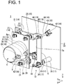
- FIGS. 1 to 4 As an embodiment of the present invention, for example, a vehicular lamp 1 shown in FIGS. 1 to 4 will be described.
- FIG. 1 is a perspective view showing a configuration of the vehicular lamp 1.
- FIG. 2 is an exploded perspective view showing the configuration of the vehicular lamp 1.
- FIG. 3 is a side view showing the configuration of the light source unit 4 provided in the vehicular lamp 1.
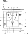
- FIG. 4 is a schematic diagram showing the arrangement of support points S1 to S6 when the light source unit 4 provided in the vehicular lamp 1 is view in the front view.
- the XYZ orthogonal coordinate system is set, and the X-axis direction is indicated as the front-rear direction (length or depth direction) of the vehicular lamp 1, the Y-axis direction is indicated as the left-right direction (width direction) of the vehicular lamp 1, and the Z-axis direction is indicated as the vertical direction (height direction) of the vehicular lamp 1.
- the present invention is applied to a vehicular headlamp mounted on both corner portions of a vehicle (not illustrated) on the front end side thereof.
- the vehicular lamp 1 has a structure in which a light source unit 4 configured to projecting light toward the front of the vehicle, i.e., in the +X-axis direction, is disposed inside a lamp body 3 composed of a housing 2 and a transparent lens cover (not illustrated).
- the housing 2 has an opening at its front surface, and the transparent lens cover covers the opening of the housing 2.
- the vehicular lamp 1 has a structure in which a holder 6 configured to hold the light source unit 4 is attached to the front surface of the housing 2 via a bracket 5, the holder 6 is supported so as to be tiltable with respect to the bracket 5, and the bracket 5 is supported so as to be tiltable with respect to the housing 2.
- An opening 5a through which the light source unit 4 penetrates is provided in a substantially central portion of the bracket 5.
- the light source unit 4 having an optical axis center O includes: a light source 7 composed of, for example, a chip LED (SMD LED) that emits white light (hereinafter simply referred to as light) L; a reflector 8 configured to reflect the light L emitted upward from the light source 7 toward the front of the vehicle; a shade 9 configured to shield (cut) a portion of the light L reflected by the reflector 8; a projection lens 10 configured to project the light L partially cut by the shade 9 toward the front of the vehicle; a substrate 11 on which the light source 7 is mounted on one surface (in the present exemplary embodiment, the upper surface); and a heat sink 12 configured to radiate heat emitted by the light source 7 while being in contact with the other surface (in the present exemplary embodiment, the lower surface) of the substrate 11.
- a light source 7 composed of, for example, a chip LED (SMD LED) that emits white light (hereinafter simply referred to as light) L
- a reflector 8 configured to reflect the light L emitted
- a light source image defined by the front end of the shade 9 is reversed and projected as a passing beam (low beam) by the projection lens 10, thereby forming a low beam light distribution pattern including a cut-off line at the upper end thereof.
- the light source unit 4 may have a configuration in which a cooling fan (not illustrated) is attached to the back surface side of the light source unit 4.
- a cooling fan (not illustrated) is attached to the back surface side of the light source unit 4.
- a light emitting element such as a laser diode (LD) may be mentioned as an example in addition to the above-described LED.
- the number of light-emitting elements is not limited to one, and may be two or more.
- the light source unit 4 may be configured to form a high-beam light distribution pattern above the low-beam light distribution pattern by disposing a second light source (not illustrated) below the shade 9, and projecting light emitted from the second light source as a traveling beam by the projection lens 10 toward the vehicle traveling direction.
- the light source unit 4 is integrally held in the holder 6 by accommodating the light source 7, the reflector 8, the shade 9, the projection lens 10, the substrate 11, and the heat sink 12, which are described above, inside the holder 6 which is in a substantially cylindrical shape.
- a flat plate-shaped flange portion 6a is provided on the outer peripheral portion of the base end of the holder 6 so as to project radially.
- the light source unit 4 is not necessarily limited to a projector-type light source unit that projects the light L toward the front of the vehicle using the above-described projection lens 10, and may be, for example, a reflector-type light source unit that projects the light L toward the front of the vehicle using a reflector including a plurality of reflection surfaces while eliminating a projection lens, or a light guide lens-type light source unit that projects the light L toward the front of the vehicle using a light guide lens.
- the vehicular lamp 1 of the present exemplary embodiment includes an optical axis adjusting mechanism 13 configured to adjust the optical axis of light projected from the light source unit 4 toward the front of the vehicle.
- the optical axis adjustment mechanism 13 has three support points S1, S2, and S3 which support the holder 6 with respect to the bracket 5, and includes, as a leveling adjustment mechanism, a first pivot portion 14 which is located at the first support point S1 among the three support points S1, S2, and S3 and configured to support the holder 6 so that the holder 6 is tiltable with respect to the bracket 5, a second pivot portion 15 which is located at the second support point S2 among the three support points S1, S2, and S3 and configured to support the holder 6 so that the holder 6 is tiltable with respect to the bracket 5, and an actuator 16 which is located at the third support point S3 among the three support points S1, S2, and S3 and configured to adjust the tilt of the holder 6 with respect to the bracket 5 in the vertical direction.
- the optical axis adjustment mechanism 13 has three support points S4, S5, and S6 which support the bracket 5 with respect to the housing 2, and includes, as an aiming adjustment mechanism, a third pivot portion 17 which is located at a fourth support point S4 among the three support points S4, S5, and S6 and configured to support the bracket 5 so that the bracket 5 is tiltable with respect to the housing 2, a left-right tilt adjustment tool 18 which is located at a fifth support point S5 among the three support points S4, S5, and S6 and configured to adjust the tilt of the bracket 5 with respect to the housing 2 in the left-right direction, and a vertical tilt adjustment tool 19 which is located at a sixth support point S6 among the three support points S4, S5, and S6 and configured to adjust the tilt of the bracket 5 with respect to the housing 2 in the vertical direction.
- the first support point S1, the second support point S2, and the third support point S3 are located outside the light source unit 4.
- a support line LS is assumed to connect the first support point S1 and the second support point S2 among these support points, and a first horizontal line LH1 is assumed to pass through the optical axis center O of the light source unit 4.
- the support line LS is set to be parallel to the first horizontal line LH1.
- a first vertical line LV1 is assumed to pass through the optical axis center O of the light source unit 4.
- the first vertical line LV1 is set to be orthogonal to the middle of the support line LS.
- the support line LS and the third support point S3 are set to be located on sides opposite to each other with the first horizontal line LH1 interposed therebetween, and the optical axis center O of the light source unit 4 is set to be located inside the area E defined by connecting the first support point S1, the second support point S2, and the third support point S3.
- the support line LS (connecting the first support point S1 and the second support point S2) and the third support point S3 are positioned above and below the first horizontal line LH, respectively, with the first horizontal line LH1 interposed therebetween. Furthermore, the third support point S3 is located on the first vertical line LV1. Further, the optical axis center O of the light source unit 4 is located substantially at the center of the area E.
- the optical axis adjusting mechanism 13 is not necessarily limited to the arrangement of the support points S1, S2, and S3 described above, and, for example, the optical axis adjusting mechanism 13 may be configured such that the support line LS (connecting the first support point S1 and the second support point S2) and the third support point S3 are located below and above the first horizontal line LH1, respectively, with the first horizontal line LH1 interposed therebetween.
- the fourth support point S4, the fifth support point S5, and the sixth support point S6 are located outside the light source unit 4.
- a second horizontal line LH2 is assumed to pass through the fourth support point S4
- a second vertical line LV2 is assumed to pass through the fourth support point S4.
- the fifth support point S5 is set to be located on the second horizontal line LH2
- the sixth support point S6 is set to be located on the second vertical line LV2.
- the fourth supporting point S4, the fifth supporting point S5, and the sixth supporting point S6 are located outside the area E defined by connecting the first supporting point S1, the second supporting point S2, and the third supporting point S3.
- the fourth support point S4 is located on the extension line of the support line LS, and the third support point S3 is located at the middle of the line connecting the fourth support point S4 and the fifth support point S5, i.e., the second horizontal line LH2.
- the fourth support point S4 is disposed in the "lower right” portion in FIG. 4 , the fifth support point S5 in the “lower left” portion in FIG. 4 , and the sixth support point S6 in the "upper right” portion in FIG. 4 , with the light source unit interposed therebetween.
- the fourth support point S4 may be positioned in any of the "lower right", “lower left”, “upper right”, or “upper left” portion with the light source unit interposed between it and the others.
- the fifth support point S5 needs to be disposed on the opposite side of the fourth support point S4 in the left-right direction with the light source unit 4 interposed therebetween in accordance with the disposition of the fourth support point S4, and the sixth support point S6 need to be disposed on the opposite side of the fourth support point S4 in the vertical direction with the light source unit 4 interposed therebetween in accordance with the disposition of the fourth support point S4.
- the first pivot portion 14 includes a first pivot shaft 20 having a spherical convex portion 20a at its tip end and attached to the bracket 5, and a first pivot bearing 21 having a spherical concave portion 21a, into which the spherical convex portion 20a is fitted, and attached to the flange portion 6a of the holder 6.
- a first shaft hole 22 for pivotally supporting the first pivot shaft 20 is provided at a position corresponding to the first support point S1 of the bracket 5.
- a first mount hole 23 into which the first pivot bearing 21 is fitted is provided at a position corresponding to the first support point S1 of the flange portion 6a (the holder 6).
- the second pivot portion 15 includes a second pivot shaft 24 having a spherical convex portion 24a at its tip end and attached to the bracket 5, and a second pivot bearing 25 having a spherical concave portion 25a, into which the spherical convex portion 24a is fitted, and attached to the flange portion 6a of the holder 6.
- a second shaft hole 26 for pivotally supporting the second pivot shaft 24 is provided at a position corresponding to the second support point S2 of the bracket 5.
- a second mount hole 27 into which the second pivot bearing 25 is fitted is provided at a position corresponding to the second support point S2 of the flange portion 6a (the holder 6).
- the actuator 16 slidably drives in the front-rear direction a slide shaft 28 provided with a spherical convex portion 28a at the distal end.
- a third pivot bearing 29 having a spherical concave portion 29a into which the spherical convex portion 28a is fitted is attached to the flange portion 6a of the holder 6.
- a fixing hole 30 for fixing the actuator 16 is provided at a position corresponding to the third support point S3 of the bracket 5.
- a third mount hole 31 into which the third pivot bearing 29 is fitted is provided at a position corresponding to the third support point S3 of the flange portion 6a (holder 6).
- the third pivot portion 17 has a third pivot shaft 32 having a spherical convex portion 32a at its tip end and attached to the housing 2, and a fourth pivot bearing 33 having a spherical concave portion 33a, in which the spherical convex portion 32a is fitted, and attached to the bracket 5.
- a third shaft hole 34 for pivotally supporting the third pivot shaft 32 is provided at a position corresponding to the fourth support point S4 of the housing 2.
- the third axial hole 34 is provided in a first boss 35 protruding from the front surface of the housing 2.
- a fourth mount hole 36 into which the fourth pivot bearing 33 is fitted is provided at a position corresponding to the fourth support point S4 of the bracket 5.
- the right/left tilt adjusting tool 18 has a first adjusting bolt 38 attached to the housing 2 via a first speed nut 37, and a first adjusting nut 39 attached to the bracket 5 in a state of being fastened to the first adjusting bolt 38.
- a first through hole 40 through which the first adjusting bolt 38 passes is provided.
- the first through hole 40 is provided in a second boss 41 protruding from the front surface of the housing 2.
- the first speed nut 37 is screwed to the first adjusting bolt 38 in a state of abutting the tip end of the second boss 41.
- the head portion of the first adjustment bolt 38 constitutes a left-right adjustment dial 38a for rotating the first adjustment bolt 38 on the rear surface side of the housing 2.
- a fifth mount hole 42 into which the first adjustment nut 39 is fitted is provided at a position corresponding to the fifth support point S5 of the bracket 5.
- the vertical tilt adjusting tool 19 has a second adjusting bolt 44 attached to the housing 2 via a second speed nut 43, and a second adjusting nut 45 attached to the bracket 5 in a state of being fastened to the second adjusting bolt 44.
- a second through hole 46 through which the second adjusting bolt 44 passes is provided at a position corresponding to the sixth support point S6 of the housing 2.
- the second through hole 46 is provided in a third boss 47 protruding from the front surface of the housing 2.
- the second speed nut 43 is screwed to the second adjusting bolt 44 in a state of abutting the tip end of the third boss 47.
- the head portion of the second adjustment bolt 44 constitutes a vertical adjustment dial 44a for rotating the second adjustment bolt 44 on the rear surface side of the housing 2.
- a sixth mount hole 48 into which the second adjustment nut 45 is fitted is provided at a position corresponding to the sixth support point S6 of the bracket 5.
- the optical axis adjusting mechanism 13 of the present exemplary embodiment it is possible to perform an aiming operation for manually adjusting the tilt of the light source unit 4 in the left-right direction by operating the left-right tilt adjusting tool 18.
- the first adjustment nut 39 fastened to the first adjustment bolt 38 slides in the front-rear direction by rotating the left-right adjustment dial 38a.
- the bracket 5 swings in the left-right direction with respect to the housing 2 with the third pivot portion 17 as a fulcrum. This makes it possible to adjust the tilt of the light source unit 4 in the left-right direction.
- the optical axis adjusting mechanism 13 it is possible to perform an aiming operation for manually adjusting the tilt of the light source unit in the vertical direction 4 by operating the vertical tilt adjusting tool 19.
- the second adjustment nut 45 fastened to the second adjustment bolt 44 slides in the front-rear direction by rotating the vertical adjustment dial 44a.
- the bracket 5 swings in the vertical direction with respect to the housing 2 with the third pivot portion 17 as a fulcrum. As a result, it is possible to adjust the tilt of the light source unit 4 in the vertical direction.
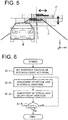
- FIG. 5 is a schematic diagram for explaining an aiming operation by the optical axis adjusting mechanism 13.
- FIG. 6 is a flowchart for explaining the aiming operation by the optical axis adjusting mechanism 13.
- FIG. 5 shows the low beam light distribution pattern P' before the aiming adjustment and the low beam light distribution pattern P after the aiming adjustment both projected toward the front of the vehicle B.
- the intersection of the horizontal axis and the vertical axis shown in FIG. 5 represents the angle reference position (0°) in front of the vehicle B.
- the reference position of the actuator 16 is set. That is, the actuator 16 is reset to confirm that the slide shaft 28 of the actuator 16 is located in the initial position.
- step S1-2 in FIG. 6 the vertical tilt of the light source unit 4 is manually adjusted by rotating the vertical adjusting dial 44a.
- the low-beam light distribution pattern P' projected toward the front of the vehicle B is adjusted so that the position thereof in the vertical direction becomes the low-beam light distribution pattern P which matches the safety standard.
- step S1-3 in FIG. 6 the tilt of the light source unit 4 in the left-right direction is manually adjusted by rotating the left-right adjusting dial 38a.
- the low-beam light distribution pattern P' projected toward the front of the vehicle B is adjusted so that the position in the left-right direction becomes the low-beam light distribution pattern P which matches the security standard.
- step S1-4 in FIG. 6 it is confirmed whether or not the positions of the low beam light distribution pattern P in the vertical direction and the left-right direction match the security standard. Then, the operations of step S1-2 and step S1-3 are repeated until the positions of the low beam light distribution pattern P in the vertical direction and the left-right direction match the safety standard. The steps S1-2 and S1-3 may be reversed.
- the vehicular lamp 1 of the present exemplary embodiment it is possible to adjust the optical axis of the light projected from the light source unit 4 toward the front of the vehicle B when the vehicle is in a stopped state, i.e., when the vehicle is horizontal, by the above-described aiming operation using the optical axis adjustment mechanism 13.
- the optical axis adjusting mechanism 13 of the present exemplary embodiment it is possible to perform a leveling operation for automatically adjusting the vertical tilt of the light source unit 4. Specifically, when the actuator 16 slidably drives the slide shaft 28 in the front-rear direction, the holder 6 swings in the vertical direction with respect to the bracket 5 with the first pivot portion 14 and the second pivot portion 15 as a fulcrum. This makes it possible to automatically adjust the vertical tilt of the light source unit 4.
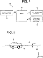
- FIG. 7 is a block diagram showing a configuration of the controller 50 for controlling the optical axis adjusting mechanism 13.
- FIG. 8 is a schematic diagram showing a change in the attitude of the vehicle B.
- FIG. 9 is a schematic view for explaining a leveling operation by the optical axis adjusting mechanism 13.
- FIG. 10 is a flowchart for explaining the leveling operation by the optical axis adjusting mechanism 13.
- the vehicular lamp 1 of the present exemplary embodiment includes a controller 50 for automatically adjusting the vertical tilt of the light source unit 4.
- the controller 50 includes a computer, or an Electronic Control Unit (ECU) 51 for controlling the driving of the actuator 16.
- ECU Electronic Control Unit
- the ECU 51 is electrically connected to the actuator 16.
- the ECU 51 expands the control program stored in the ROM into the RAM and executes the program, and controls the driving of the actuator 16 in accordance with the result of the operation performed by the ECU.
- the ECU 51 is electrically connected to a tilt detecting section 52 for detecting the tilt of the vehicle B in the front-rear direction.
- a tilt detecting unit 52 any one may be used as long as the tilt of the vehicle B in the front-rear direction can be detected, and for example, a tilt sensor mounted on the vehicle B, an acceleration (G) sensor, an angular velocity (gyro) sensor, or the like can be used.
- the tilt detecting section 52 supplies the tilt detecting signal D1 detected by the tilt detecting section 52 to the ECU 51.
- the ECU 51 is electrically connected to a position detecting unit 53 for detecting the position of the slide shaft 28 of the actuator 16.
- a position detecting unit 53 As the position detecting unit 53, an encoder or the like provided in the actuator 16 can be used.
- the position detecting unit 53 supplies the position detection signal D2 detected by the position detecting unit 53 to the ECU 51.
- FIG. 8 a case is exemplified in which the optical axis AX' of the vehicle B is inclined upward by 1° while the vehicle B is traveling (when the vehicle is inclined) with reference to the optical axis AX when the vehicle B is in a stopped state (when the vehicle is horizontal). Therefore, in this case, leveling adjustment for lowering the optical axis AX by -1° is necessary.
- FIG. 9 the low beam light distribution pattern P' before leveling adjustment and the low beam light distribution pattern P after leveling adjustment both projected toward the front of the vehicle B are shown.
- the intersection of the horizontal axis and the vertical axis shown in FIG. 9 represents the angle reference position (0°) in front of the vehicle B.
- step S2-1 in FIG. 10 the tilt detection signal D1 is inputted from the tilt detecting unit 52 to the ECU 51 of the leveling operation.
- step S2-2 in FIG. 10 the position detection signal D2 is inputted from the position detecting unit 53 to the ECU 51.
- step S2-3 in FIG. 10 the ECU 51 performs a calculation on the basis of the tilt detection signal D1 and the position detection signal D2 to calculate the slide amount of the slide shaft 28. Then, a drive signal D3 based on the calculation result is generated and supplied (output) to the actuator 16.
- step S2-4 in FIG. 10 the actuator 16 slides the slide shaft 28 on the basis of the drive signal D3 supplied from the ECU 51.
- the low beam light distribution pattern P' projected toward the front of the vehicle B is adjusted so that the position in the vertical direction of the optical axis AX becomes the position in which the low beam light distribution pattern P is lowered by -1°.
- the vehicular lamp 1 of the present exemplary embodiment it is possible to correct the variation of the optical axis due to the attitude change of the vehicle B by such a leveling operation using the optical axis adjusting mechanism 13, i.e., by a leveling operation of automatically adjusting the optical axis of the light projected from the light source unit 4 toward the front of the vehicle B in the vertical direction when the vehicle is traveling (when the vehicle is inclined).
- the first support point S1, the second support point S2, and the third support point S3 are located outside the light source unit 4 when the light source unit 4 is view in the front view.
- the light source unit 4 disposed inside the lamp body 3 can be stably supported.
- the support line LS assumed to connect the first support point S1 and the second support point S2 is parallel to the first horizontal line LH1 assumed to pass through the light axis center O of the light source unit 4, and that the first vertical line LV1 assumed to pass through the optical axis center O of the light source unit 4 is orthogonal to the support line LS.
- the support line LS and the third support point S3 are located on the respective sides opposite to each other with the first horizontal line LH1 interposed therebetween, and the optical axis center O of the light source unit 4 is located inside the area E defined by connecting the first support point S1, the second support point S2, and the third support point S3.
- the support line LS (connecting the first support point S1 and the second support point S2) and the third support point S3 are positioned above and below the first horizontal line LH1, respectively, with the first horizontal line LH1 interposed therebetween.
- the third support point S3 is located on the first vertical line LV1.
- the optical axis center O of the light source unit 4 is located substantially at the center of the area E. In this case, it is possible to perform the leveling operation by the optical axis adjusting mechanism 13 with high accuracy while suppressing the rattling of the light source unit 4 due to vibration, shock, or the like when the vehicle is traveling.
- the fourth support point S4, the fifth support point S5, and the sixth support point S6 are located outside the light source unit 4.
- the light source unit 4 disposed inside the lamp body 3 can be stably supported.
- the fifth support point S5 is positioned on the second horizontal line LH2 assumed to pass through the fourth support point S4, and the sixth support point S6 is positioned on the second vertical line LV2 assumed to pass through the fourth support point S4.
- the bracket 5 it is possible to swing the bracket 5 with respect to the housing 2 in a stable state in the left-right direction and the vertical direction with the third pivot portion 17 as a fulcrum. Therefore, in the optical axis adjusting mechanism 13 of the present exemplary embodiment, it is possible to stably perform an aiming operation for manually adjusting the tilt of the light source unit 4 in the left-right direction and the vertical direction. In addition, since the tilt adjustment of one of the left and right directions and the vertical direction is not affected by the tilt adjustment of the other, it is possible to easily and accurately perform the aiming operation by the optical axis adjustment mechanism 13.
- the fourth support point S4, the fifth support point S5, and the sixth support point S6 are located outside the area E defined by connecting the first support point S1, the second support point S2, and the third support point S3.
- the fourth support point S4 is located on the support line LS, and the third support point S3 is located in the middle of the second horizontal line LH2. In this case, it is possible to perform the leveling operation by the optical axis adjusting mechanism 13 with high accuracy while suppressing rattling of the light source unit 4 due to vibration, shock, or the like when the vehicle is traveling.
- the light source unit 4 can be supported in a stable state, and the optical axis adjustment by the optical axis adjustment mechanism 13 can be stably performed.
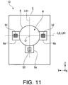
- FIG. 11 is a schematic diagram showing another arrangement example of the first, second, and third support points S1, S2, and S3 when the light source unit 4 is view in the front view.
- the holder 6 holding the light source unit 4, i.e., the flange 6a, can be downsized.
- an extension (not illustrated) is arranged inside the lamp body 3, the clearance with the light source unit 4 can be reduced, so that the appearance can be improved.
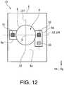
- FIG. 12 is a schematic diagram showing another arrangement example of the first, second, and third support points S1, S2, and S3 when the light source unit 4 is viewed in the front view.
- the actuator 16 is arranged asymmetrically with respect to the first vertical lines LV1, the holder 6, i.e., the flanges 6a, for holding the light source unit 4 can be further miniaturized.
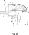
- the rotation center T of the light source unit 4 may be configured to match the center of gravity G of the light source unit 4.
- FIG. 13 is a schematic diagram showing an example of the rotation center T and the center of gravity G of the light source unit 4 when the light source unit 4 is viewed from the side surface side.
- the inertial mass of the light source unit 4 that rotates around the support line LS as the holder 6 swings in the vertical direction with respect to the bracket 5 can be reduced.
- the load applied to the actuator 16 can be reduced, so that the actuator 16 can be miniaturized.
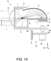
- the rotation center T of the light source unit 4 may be positioned forward of the center of gravity G of the light source unit 4 when the light source unit 4 is viewed from the side.
- FIG. 14 is a schematic diagram showing another example of the rotation center T and the center of gravity G of the light source unit 4 when the light source unit 4 is viewed from the side surface side.
- the center of gravity G of the light source unit 4 is located inside the area defined by connecting the first support point S1 and the second support point S2 positioned forward of the center of gravity G of the light source unit 4 and the third support point S3 positioned rearward of the center of gravity G of the light source unit 4, whereby it is possible to further improve the stability of the light source unit 4 against vibration, shock, or the like when the vehicle is traveling.
Landscapes
- Engineering & Computer Science (AREA)
- Mechanical Engineering (AREA)
- Lighting Device Outwards From Vehicle And Optical Signal (AREA)
- Non-Portable Lighting Devices Or Systems Thereof (AREA)
- Fastening Of Light Sources Or Lamp Holders (AREA)
Applications Claiming Priority (1)
| Application Number | Priority Date | Filing Date | Title |
|---|---|---|---|
| JP2018062653A JP7193242B2 (ja) | 2018-03-28 | 2018-03-28 | 車両用灯具 |
Publications (1)
| Publication Number | Publication Date |
|---|---|
| EP3552877A1 true EP3552877A1 (de) | 2019-10-16 |
Family
ID=66041133
Family Applications (1)
| Application Number | Title | Priority Date | Filing Date |
|---|---|---|---|
| EP19165542.2A Withdrawn EP3552877A1 (de) | 2018-03-28 | 2019-03-27 | Fahrzeuglampe |
Country Status (3)
| Country | Link |
|---|---|
| US (1) | US10807514B2 (de) |
| EP (1) | EP3552877A1 (de) |
| JP (1) | JP7193242B2 (de) |
Families Citing this family (8)
| Publication number | Priority date | Publication date | Assignee | Title |
|---|---|---|---|---|
| WO2021085147A1 (ja) * | 2019-10-31 | 2021-05-06 | 株式会社小糸製作所 | 光学ユニット |
| US11105484B2 (en) * | 2019-11-08 | 2021-08-31 | Sl Corporation | Lamp for vehicle |
| FR3109621B1 (fr) * | 2020-04-27 | 2022-04-08 | Valeo Vision | Dispositif d’éclairage de véhicule automobile présentant un aspect sans glace |
| JP2024121864A (ja) * | 2023-02-28 | 2024-09-09 | 市光工業株式会社 | 車両用灯具 |
| US12291141B2 (en) * | 2023-06-06 | 2025-05-06 | Toyota Motor Engineering & Manufacturing North America, Inc. | Headlight adjustment system with measuring assembly including optical beam extending past an articulating reference |
| JP2025165428A (ja) * | 2024-04-23 | 2025-11-05 | スタンレー電気株式会社 | レベリングアクチュエータ及び車両用灯具 |
| JP2025187157A (ja) * | 2024-06-13 | 2025-12-25 | スタンレー電気株式会社 | 車両用灯具 |
| CN121305528B (zh) * | 2025-12-12 | 2026-04-07 | 南京依维柯汽车有限公司 | 车载路面分隔物检测方法和系统 |
Citations (6)
| Publication number | Priority date | Publication date | Assignee | Title |
|---|---|---|---|---|
| JP2000057824A (ja) | 1998-08-04 | 2000-02-25 | Koito Mfg Co Ltd | 車輌用前照灯 |
| US20090207626A1 (en) * | 2008-02-15 | 2009-08-20 | Sl Corporation | Headlamp assembly for vehicles |
| EP2338728A1 (de) * | 2009-12-25 | 2011-06-29 | Koito Manufacturing Co., Ltd. | Fahrzeugscheinwerfer |
| US20130121013A1 (en) * | 2011-11-11 | 2013-05-16 | Koito Manufacturing Co., Ltd. | Vehicular headlamp and replacement method for leveling actuator of the vehicular headlamp |
| WO2016201466A1 (de) * | 2015-06-19 | 2016-12-22 | Zkw Group Gmbh | Fahrzeugscheinwerfer mit einstellbaren optischen baueinheiten |
| JP6176931B2 (ja) * | 2013-01-28 | 2017-08-09 | 株式会社小糸製作所 | 車輌用前照灯 |
Family Cites Families (7)
| Publication number | Priority date | Publication date | Assignee | Title |
|---|---|---|---|---|
| JP3998970B2 (ja) * | 2001-12-26 | 2007-10-31 | 株式会社小糸製作所 | 車両用灯具 |
| JP4688220B2 (ja) * | 2006-10-10 | 2011-05-25 | 株式会社小糸製作所 | 車輌用灯具 |
| JP4518505B2 (ja) * | 2006-10-12 | 2010-08-04 | 株式会社小糸製作所 | 車輌用灯具 |
| JP4683658B2 (ja) * | 2006-12-01 | 2011-05-18 | 株式会社小糸製作所 | 車輌用灯具 |
| JP4711983B2 (ja) | 2007-02-21 | 2011-06-29 | 株式会社小糸製作所 | 車輌用灯具 |
| JP2010015888A (ja) | 2008-07-04 | 2010-01-21 | Stanley Electric Co Ltd | 車両用灯具ユニットの光軸調整装置 |
| JP2015015187A (ja) | 2013-07-05 | 2015-01-22 | 株式会社小糸製作所 | 車輌用前照灯 |
-
2018
- 2018-03-28 JP JP2018062653A patent/JP7193242B2/ja active Active
-
2019
- 2019-03-26 US US16/365,291 patent/US10807514B2/en active Active
- 2019-03-27 EP EP19165542.2A patent/EP3552877A1/de not_active Withdrawn
Patent Citations (7)
| Publication number | Priority date | Publication date | Assignee | Title |
|---|---|---|---|---|
| JP2000057824A (ja) | 1998-08-04 | 2000-02-25 | Koito Mfg Co Ltd | 車輌用前照灯 |
| US6220735B1 (en) | 1998-08-04 | 2001-04-24 | Koito Manufacturing Co., Ltd. | Aiming and leveling mechanism for a vehicle head lamp |
| US20090207626A1 (en) * | 2008-02-15 | 2009-08-20 | Sl Corporation | Headlamp assembly for vehicles |
| EP2338728A1 (de) * | 2009-12-25 | 2011-06-29 | Koito Manufacturing Co., Ltd. | Fahrzeugscheinwerfer |
| US20130121013A1 (en) * | 2011-11-11 | 2013-05-16 | Koito Manufacturing Co., Ltd. | Vehicular headlamp and replacement method for leveling actuator of the vehicular headlamp |
| JP6176931B2 (ja) * | 2013-01-28 | 2017-08-09 | 株式会社小糸製作所 | 車輌用前照灯 |
| WO2016201466A1 (de) * | 2015-06-19 | 2016-12-22 | Zkw Group Gmbh | Fahrzeugscheinwerfer mit einstellbaren optischen baueinheiten |
Also Published As
| Publication number | Publication date |
|---|---|
| US10807514B2 (en) | 2020-10-20 |
| US20190299845A1 (en) | 2019-10-03 |
| JP7193242B2 (ja) | 2022-12-20 |
| JP2019175685A (ja) | 2019-10-10 |
Similar Documents
| Publication | Publication Date | Title |
|---|---|---|
| US10807514B2 (en) | Vehicular lamp | |
| JP6883081B2 (ja) | 車両用灯具システム、および車両用灯具の制御装置 | |
| CN102563546B (zh) | 车辆用灯具的控制装置、系统及控制方法 | |
| JP5761982B2 (ja) | 車両用灯具の制御装置 | |
| CN103574459B (zh) | 车辆用前照灯 | |
| JP5749074B2 (ja) | 車両用灯具の制御装置、および車両用灯具システム | |
| JP6377400B2 (ja) | 車両用灯具 | |
| JP7550938B2 (ja) | 車両用灯具の制御装置、車両用灯具システムおよび車両用灯具の制御方法 | |
| JP5749081B2 (ja) | 車両用灯具の制御装置および車両用灯具システム | |
| JP6445308B2 (ja) | 車両用灯具の制御装置 | |
| JP2021138278A (ja) | 車両用灯具の制御装置および車両用灯具システム | |
| JP5780846B2 (ja) | 車両用灯具の制御装置および車両用灯具システム | |
| JP2010015888A (ja) | 車両用灯具ユニットの光軸調整装置 | |
| JP6004916B2 (ja) | 車両用灯具の制御装置及び車両用灯具システム | |
| EP4317770B1 (de) | Fahrzeugleuchte | |
| JP2020064840A (ja) | 車両用灯具 | |
| JP2024131522A (ja) | 車両用灯具 | |
| WO2025159051A1 (ja) | 車両用灯具の制御装置、ecu、車両用灯具システム、コンピュータプログラム、および車両用灯具の制御方法 | |
| JP2021072199A (ja) | 車両用前照灯の可動シェード機構及び車両用前照灯 | |
| JP2018190633A (ja) | 車両用前照灯 | |
| JPH0740277U (ja) | ヘッドランプレベリングシステム |
Legal Events
| Date | Code | Title | Description |
|---|---|---|---|
| PUAI | Public reference made under article 153(3) epc to a published international application that has entered the european phase |
Free format text: ORIGINAL CODE: 0009012 |
|
| STAA | Information on the status of an ep patent application or granted ep patent |
Free format text: STATUS: THE APPLICATION HAS BEEN PUBLISHED |
|
| AK | Designated contracting states |
Kind code of ref document: A1 Designated state(s): AL AT BE BG CH CY CZ DE DK EE ES FI FR GB GR HR HU IE IS IT LI LT LU LV MC MK MT NL NO PL PT RO RS SE SI SK SM TR |
|
| AX | Request for extension of the european patent |
Extension state: BA ME |
|
| STAA | Information on the status of an ep patent application or granted ep patent |
Free format text: STATUS: REQUEST FOR EXAMINATION WAS MADE |
|
| 17P | Request for examination filed |
Effective date: 20200416 |
|
| RBV | Designated contracting states (corrected) |
Designated state(s): AL AT BE BG CH CY CZ DE DK EE ES FI FR GB GR HR HU IE IS IT LI LT LU LV MC MK MT NL NO PL PT RO RS SE SI SK SM TR |
|
| STAA | Information on the status of an ep patent application or granted ep patent |
Free format text: STATUS: EXAMINATION IS IN PROGRESS |
|
| 17Q | First examination report despatched |
Effective date: 20220603 |
|
| STAA | Information on the status of an ep patent application or granted ep patent |
Free format text: STATUS: THE APPLICATION IS DEEMED TO BE WITHDRAWN |
|
| 18D | Application deemed to be withdrawn |
Effective date: 20250103 |