EP3552773B1 - System und verfahren zum entfernen eines werkstücks aus einer herstellungsvorrichtung - Google Patents
System und verfahren zum entfernen eines werkstücks aus einer herstellungsvorrichtung Download PDFInfo
- Publication number
- EP3552773B1 EP3552773B1 EP19167769.9A EP19167769A EP3552773B1 EP 3552773 B1 EP3552773 B1 EP 3552773B1 EP 19167769 A EP19167769 A EP 19167769A EP 3552773 B1 EP3552773 B1 EP 3552773B1
- Authority
- EP
- European Patent Office
- Prior art keywords
- workpiece
- vertical
- attachment
- assembly
- horizontal
- Prior art date
- Legal status (The legal status is an assumption and is not a legal conclusion. Google has not performed a legal analysis and makes no representation as to the accuracy of the status listed.)
- Active
Links
Images










Classifications
-
- G—PHYSICS
- G05—CONTROLLING; REGULATING
- G05B—CONTROL OR REGULATING SYSTEMS IN GENERAL; FUNCTIONAL ELEMENTS OF SUCH SYSTEMS; MONITORING OR TESTING ARRANGEMENTS FOR SUCH SYSTEMS OR ELEMENTS
- G05B19/00—Program-control systems
- G05B19/02—Program-control systems electric
- G05B19/418—Total factory control, i.e. centrally controlling a plurality of machines, e.g. direct or distributed numerical control [DNC], flexible manufacturing systems [FMS], integrated manufacturing systems [IMS] or computer integrated manufacturing [CIM]
- G05B19/4189—Total factory control, i.e. centrally controlling a plurality of machines, e.g. direct or distributed numerical control [DNC], flexible manufacturing systems [FMS], integrated manufacturing systems [IMS] or computer integrated manufacturing [CIM] characterised by the transport system
-
- B—PERFORMING OPERATIONS; TRANSPORTING
- B25—HAND TOOLS; PORTABLE POWER-DRIVEN TOOLS; MANIPULATORS
- B25J—MANIPULATORS; CHAMBERS PROVIDED WITH MANIPULATION DEVICES
- B25J9/00—Program-controlled manipulators
- B25J9/02—Program-controlled manipulators characterised by movement of the arms, e.g. cartesian coordinate type
- B25J9/023—Cartesian coordinate type
- B25J9/026—Gantry-type
-
- B—PERFORMING OPERATIONS; TRANSPORTING
- B23—MACHINE TOOLS; METAL-WORKING NOT OTHERWISE PROVIDED FOR
- B23Q—DETAILS, COMPONENTS, OR ACCESSORIES FOR MACHINE TOOLS, e.g. ARRANGEMENTS FOR COPYING OR CONTROLLING; MACHINE TOOLS IN GENERAL CHARACTERISED BY THE CONSTRUCTION OF PARTICULAR DETAILS OR COMPONENTS; COMBINATIONS OR ASSOCIATIONS OF METAL-WORKING MACHINES, NOT DIRECTED TO A PARTICULAR RESULT
- B23Q1/00—Members which are comprised in the general build-up of a form of machine, particularly relatively large fixed members
- B23Q1/25—Movable or adjustable work or tool supports
- B23Q1/44—Movable or adjustable work or tool supports using particular mechanisms
- B23Q1/50—Movable or adjustable work or tool supports using particular mechanisms with rotating pairs only, the rotating pairs being the first two elements of the mechanism
- B23Q1/52—Movable or adjustable work or tool supports using particular mechanisms with rotating pairs only, the rotating pairs being the first two elements of the mechanism a single rotating pair
- B23Q1/525—Movable or adjustable work or tool supports using particular mechanisms with rotating pairs only, the rotating pairs being the first two elements of the mechanism a single rotating pair which is parallel to the working surface
-
- B—PERFORMING OPERATIONS; TRANSPORTING
- B23—MACHINE TOOLS; METAL-WORKING NOT OTHERWISE PROVIDED FOR
- B23Q—DETAILS, COMPONENTS, OR ACCESSORIES FOR MACHINE TOOLS, e.g. ARRANGEMENTS FOR COPYING OR CONTROLLING; MACHINE TOOLS IN GENERAL CHARACTERISED BY THE CONSTRUCTION OF PARTICULAR DETAILS OR COMPONENTS; COMBINATIONS OR ASSOCIATIONS OF METAL-WORKING MACHINES, NOT DIRECTED TO A PARTICULAR RESULT
- B23Q1/00—Members which are comprised in the general build-up of a form of machine, particularly relatively large fixed members
- B23Q1/25—Movable or adjustable work or tool supports
- B23Q1/44—Movable or adjustable work or tool supports using particular mechanisms
- B23Q1/56—Movable or adjustable work or tool supports using particular mechanisms with sliding pairs only, the sliding pairs being the first two elements of the mechanism
- B23Q1/60—Movable or adjustable work or tool supports using particular mechanisms with sliding pairs only, the sliding pairs being the first two elements of the mechanism two sliding pairs only, the sliding pairs being the first two elements of the mechanism
- B23Q1/62—Movable or adjustable work or tool supports using particular mechanisms with sliding pairs only, the sliding pairs being the first two elements of the mechanism two sliding pairs only, the sliding pairs being the first two elements of the mechanism with perpendicular axes, e.g. cross-slides
- B23Q1/621—Movable or adjustable work or tool supports using particular mechanisms with sliding pairs only, the sliding pairs being the first two elements of the mechanism two sliding pairs only, the sliding pairs being the first two elements of the mechanism with perpendicular axes, e.g. cross-slides a single sliding pair followed perpendicularly by a single sliding pair
- B23Q1/626—Movable or adjustable work or tool supports using particular mechanisms with sliding pairs only, the sliding pairs being the first two elements of the mechanism two sliding pairs only, the sliding pairs being the first two elements of the mechanism with perpendicular axes, e.g. cross-slides a single sliding pair followed perpendicularly by a single sliding pair followed perpendicularly by a single sliding pair
-
- B—PERFORMING OPERATIONS; TRANSPORTING
- B23—MACHINE TOOLS; METAL-WORKING NOT OTHERWISE PROVIDED FOR
- B23Q—DETAILS, COMPONENTS, OR ACCESSORIES FOR MACHINE TOOLS, e.g. ARRANGEMENTS FOR COPYING OR CONTROLLING; MACHINE TOOLS IN GENERAL CHARACTERISED BY THE CONSTRUCTION OF PARTICULAR DETAILS OR COMPONENTS; COMBINATIONS OR ASSOCIATIONS OF METAL-WORKING MACHINES, NOT DIRECTED TO A PARTICULAR RESULT
- B23Q1/00—Members which are comprised in the general build-up of a form of machine, particularly relatively large fixed members
- B23Q1/25—Movable or adjustable work or tool supports
- B23Q1/64—Movable or adjustable work or tool supports characterised by the purpose of the movement
- B23Q1/66—Worktables interchangeably movable into operating positions
-
- B—PERFORMING OPERATIONS; TRANSPORTING
- B23—MACHINE TOOLS; METAL-WORKING NOT OTHERWISE PROVIDED FOR
- B23Q—DETAILS, COMPONENTS, OR ACCESSORIES FOR MACHINE TOOLS, e.g. ARRANGEMENTS FOR COPYING OR CONTROLLING; MACHINE TOOLS IN GENERAL CHARACTERISED BY THE CONSTRUCTION OF PARTICULAR DETAILS OR COMPONENTS; COMBINATIONS OR ASSOCIATIONS OF METAL-WORKING MACHINES, NOT DIRECTED TO A PARTICULAR RESULT
- B23Q1/00—Members which are comprised in the general build-up of a form of machine, particularly relatively large fixed members
- B23Q1/70—Stationary or movable members for carrying working-spindles for attachment of tools or work
-
- B—PERFORMING OPERATIONS; TRANSPORTING
- B23—MACHINE TOOLS; METAL-WORKING NOT OTHERWISE PROVIDED FOR
- B23Q—DETAILS, COMPONENTS, OR ACCESSORIES FOR MACHINE TOOLS, e.g. ARRANGEMENTS FOR COPYING OR CONTROLLING; MACHINE TOOLS IN GENERAL CHARACTERISED BY THE CONSTRUCTION OF PARTICULAR DETAILS OR COMPONENTS; COMBINATIONS OR ASSOCIATIONS OF METAL-WORKING MACHINES, NOT DIRECTED TO A PARTICULAR RESULT
- B23Q3/00—Devices holding, supporting, or positioning work or tools, of a kind normally removable from the machine
- B23Q3/02—Devices holding, supporting, or positioning work or tools, of a kind normally removable from the machine for mounting on a work-table, tool-slide, or analogous part
- B23Q3/06—Work-clamping means
- B23Q3/062—Work-clamping means adapted for holding workpieces having a special form or being made from a special material
- B23Q3/063—Work-clamping means adapted for holding workpieces having a special form or being made from a special material for holding turbine blades
-
- B—PERFORMING OPERATIONS; TRANSPORTING
- B23—MACHINE TOOLS; METAL-WORKING NOT OTHERWISE PROVIDED FOR
- B23Q—DETAILS, COMPONENTS, OR ACCESSORIES FOR MACHINE TOOLS, e.g. ARRANGEMENTS FOR COPYING OR CONTROLLING; MACHINE TOOLS IN GENERAL CHARACTERISED BY THE CONSTRUCTION OF PARTICULAR DETAILS OR COMPONENTS; COMBINATIONS OR ASSOCIATIONS OF METAL-WORKING MACHINES, NOT DIRECTED TO A PARTICULAR RESULT
- B23Q3/00—Devices holding, supporting, or positioning work or tools, of a kind normally removable from the machine
- B23Q3/02—Devices holding, supporting, or positioning work or tools, of a kind normally removable from the machine for mounting on a work-table, tool-slide, or analogous part
- B23Q3/06—Work-clamping means
- B23Q3/08—Work-clamping means other than mechanically-actuated
-
- B—PERFORMING OPERATIONS; TRANSPORTING
- B23—MACHINE TOOLS; METAL-WORKING NOT OTHERWISE PROVIDED FOR
- B23Q—DETAILS, COMPONENTS, OR ACCESSORIES FOR MACHINE TOOLS, e.g. ARRANGEMENTS FOR COPYING OR CONTROLLING; MACHINE TOOLS IN GENERAL CHARACTERISED BY THE CONSTRUCTION OF PARTICULAR DETAILS OR COMPONENTS; COMBINATIONS OR ASSOCIATIONS OF METAL-WORKING MACHINES, NOT DIRECTED TO A PARTICULAR RESULT
- B23Q39/00—Metal-working machines incorporating a plurality of sub-assemblies, each capable of performing a metal-working operation
- B23Q39/02—Metal-working machines incorporating a plurality of sub-assemblies, each capable of performing a metal-working operation the sub-assemblies being capable of being brought to act at a single operating station
- B23Q39/028—Metal-working machines incorporating a plurality of sub-assemblies, each capable of performing a metal-working operation the sub-assemblies being capable of being brought to act at a single operating station with a plurality of workholder per toolhead in operating position
-
- B—PERFORMING OPERATIONS; TRANSPORTING
- B25—HAND TOOLS; PORTABLE POWER-DRIVEN TOOLS; MANIPULATORS
- B25B—TOOLS OR BENCH DEVICES NOT OTHERWISE PROVIDED FOR, FOR FASTENING, CONNECTING, DISENGAGING, OR HOLDING
- B25B11/00—Work holders not covered by any preceding group in the subclass, e.g. magnetic work holders, vacuum work holders
- B25B11/005—Vacuum work holders
-
- B—PERFORMING OPERATIONS; TRANSPORTING
- B25—HAND TOOLS; PORTABLE POWER-DRIVEN TOOLS; MANIPULATORS
- B25B—TOOLS OR BENCH DEVICES NOT OTHERWISE PROVIDED FOR, FOR FASTENING, CONNECTING, DISENGAGING, OR HOLDING
- B25B5/00—Clamps
- B25B5/14—Clamps for work of special profile
-
- B—PERFORMING OPERATIONS; TRANSPORTING
- B25—HAND TOOLS; PORTABLE POWER-DRIVEN TOOLS; MANIPULATORS
- B25B—TOOLS OR BENCH DEVICES NOT OTHERWISE PROVIDED FOR, FOR FASTENING, CONNECTING, DISENGAGING, OR HOLDING
- B25B5/00—Clamps
- B25B5/16—Details, e.g. jaws, jaw attachments
-
- B—PERFORMING OPERATIONS; TRANSPORTING
- B25—HAND TOOLS; PORTABLE POWER-DRIVEN TOOLS; MANIPULATORS
- B25J—MANIPULATORS; CHAMBERS PROVIDED WITH MANIPULATION DEVICES
- B25J15/00—Gripping heads and other end effectors
- B25J15/0028—Gripping heads and other end effectors with movable, e.g. pivoting gripping jaw surfaces
-
- B—PERFORMING OPERATIONS; TRANSPORTING
- B25—HAND TOOLS; PORTABLE POWER-DRIVEN TOOLS; MANIPULATORS
- B25J—MANIPULATORS; CHAMBERS PROVIDED WITH MANIPULATION DEVICES
- B25J15/00—Gripping heads and other end effectors
- B25J15/0052—Gripping heads and other end effectors multiple gripper units or multiple end effectors
- B25J15/0061—Gripping heads and other end effectors multiple gripper units or multiple end effectors mounted on a modular gripping structure
-
- B—PERFORMING OPERATIONS; TRANSPORTING
- B25—HAND TOOLS; PORTABLE POWER-DRIVEN TOOLS; MANIPULATORS
- B25J—MANIPULATORS; CHAMBERS PROVIDED WITH MANIPULATION DEVICES
- B25J15/00—Gripping heads and other end effectors
- B25J15/06—Gripping heads and other end effectors with vacuum or magnetic holding means
- B25J15/0616—Gripping heads and other end effectors with vacuum or magnetic holding means with vacuum
-
- B—PERFORMING OPERATIONS; TRANSPORTING
- B64—AIRCRAFT; AVIATION; COSMONAUTICS
- B64F—GROUND OR AIRCRAFT-CARRIER-DECK INSTALLATIONS SPECIALLY ADAPTED FOR USE IN CONNECTION WITH AIRCRAFT; DESIGNING, MANUFACTURING, ASSEMBLING, CLEANING, MAINTAINING OR REPAIRING AIRCRAFT, NOT OTHERWISE PROVIDED FOR; HANDLING, TRANSPORTING, TESTING OR INSPECTING AIRCRAFT COMPONENTS, NOT OTHERWISE PROVIDED FOR
- B64F5/00—Designing, manufacturing, assembling, cleaning, maintaining or repairing aircraft, not otherwise provided for; Handling, transporting, testing or inspecting aircraft components, not otherwise provided for
- B64F5/10—Manufacturing or assembling aircraft, e.g. jigs therefor
-
- G—PHYSICS
- G05—CONTROLLING; REGULATING
- G05B—CONTROL OR REGULATING SYSTEMS IN GENERAL; FUNCTIONAL ELEMENTS OF SUCH SYSTEMS; MONITORING OR TESTING ARRANGEMENTS FOR SUCH SYSTEMS OR ELEMENTS
- G05B2219/00—Program-control systems
- G05B2219/30—Nc systems
- G05B2219/35—Nc in input of data, input till input file format
- G05B2219/35191—Project workpiece and gripper, control relative movement, store result
-
- Y—GENERAL TAGGING OF NEW TECHNOLOGICAL DEVELOPMENTS; GENERAL TAGGING OF CROSS-SECTIONAL TECHNOLOGIES SPANNING OVER SEVERAL SECTIONS OF THE IPC; TECHNICAL SUBJECTS COVERED BY FORMER USPC CROSS-REFERENCE ART COLLECTIONS [XRACs] AND DIGESTS
- Y10—TECHNICAL SUBJECTS COVERED BY FORMER USPC
- Y10T—TECHNICAL SUBJECTS COVERED BY FORMER US CLASSIFICATION
- Y10T29/00—Metal working
- Y10T29/49—Method of mechanical manufacture
-
- Y—GENERAL TAGGING OF NEW TECHNOLOGICAL DEVELOPMENTS; GENERAL TAGGING OF CROSS-SECTIONAL TECHNOLOGIES SPANNING OVER SEVERAL SECTIONS OF THE IPC; TECHNICAL SUBJECTS COVERED BY FORMER USPC CROSS-REFERENCE ART COLLECTIONS [XRACs] AND DIGESTS
- Y10—TECHNICAL SUBJECTS COVERED BY FORMER USPC
- Y10T—TECHNICAL SUBJECTS COVERED BY FORMER US CLASSIFICATION
- Y10T29/00—Metal working
- Y10T29/51—Plural diverse manufacturing apparatus including means for metal shaping or assembling
- Y10T29/5124—Plural diverse manufacturing apparatus including means for metal shaping or assembling with means to feed work intermittently from one tool station to another
-
- Y—GENERAL TAGGING OF NEW TECHNOLOGICAL DEVELOPMENTS; GENERAL TAGGING OF CROSS-SECTIONAL TECHNOLOGIES SPANNING OVER SEVERAL SECTIONS OF THE IPC; TECHNICAL SUBJECTS COVERED BY FORMER USPC CROSS-REFERENCE ART COLLECTIONS [XRACs] AND DIGESTS
- Y10—TECHNICAL SUBJECTS COVERED BY FORMER USPC
- Y10T—TECHNICAL SUBJECTS COVERED BY FORMER US CLASSIFICATION
- Y10T29/00—Metal working
- Y10T29/51—Plural diverse manufacturing apparatus including means for metal shaping or assembling
- Y10T29/5136—Separate tool stations for selective or successive operation on work
-
- Y—GENERAL TAGGING OF NEW TECHNOLOGICAL DEVELOPMENTS; GENERAL TAGGING OF CROSS-SECTIONAL TECHNOLOGIES SPANNING OVER SEVERAL SECTIONS OF THE IPC; TECHNICAL SUBJECTS COVERED BY FORMER USPC CROSS-REFERENCE ART COLLECTIONS [XRACs] AND DIGESTS
- Y10—TECHNICAL SUBJECTS COVERED BY FORMER USPC
- Y10T—TECHNICAL SUBJECTS COVERED BY FORMER US CLASSIFICATION
- Y10T409/00—Gear cutting, milling, or planing
- Y10T409/30—Milling
- Y10T409/304088—Milling with means to remove chip
-
- Y—GENERAL TAGGING OF NEW TECHNOLOGICAL DEVELOPMENTS; GENERAL TAGGING OF CROSS-SECTIONAL TECHNOLOGIES SPANNING OVER SEVERAL SECTIONS OF THE IPC; TECHNICAL SUBJECTS COVERED BY FORMER USPC CROSS-REFERENCE ART COLLECTIONS [XRACs] AND DIGESTS
- Y10—TECHNICAL SUBJECTS COVERED BY FORMER USPC
- Y10T—TECHNICAL SUBJECTS COVERED BY FORMER US CLASSIFICATION
- Y10T409/00—Gear cutting, milling, or planing
- Y10T409/30—Milling
- Y10T409/309576—Machine frame
-
- Y—GENERAL TAGGING OF NEW TECHNOLOGICAL DEVELOPMENTS; GENERAL TAGGING OF CROSS-SECTIONAL TECHNOLOGIES SPANNING OVER SEVERAL SECTIONS OF THE IPC; TECHNICAL SUBJECTS COVERED BY FORMER USPC CROSS-REFERENCE ART COLLECTIONS [XRACs] AND DIGESTS
- Y10—TECHNICAL SUBJECTS COVERED BY FORMER USPC
- Y10T—TECHNICAL SUBJECTS COVERED BY FORMER US CLASSIFICATION
- Y10T82/00—Turning
- Y10T82/25—Lathe
- Y10T82/2514—Lathe with work feeder or remover
Definitions
- the field relates generally to manufacturing and, more particularly, to a system and method for removing a workpiece from a manufacturing fixture.
- the manufacturing of a barrel section of an aircraft fuselage may involve placing a plurality of uncured or precured composite stringers in a corresponding plurality of grooves extending axially along a surface of a rotatable layup mandrel. Multiple plies of composite material may then be laid up over the layup mandrel and stringers as the layup mandrel is rotated to form a skin over the stringers. After layup is complete, the layup mandrel may be moved into an autoclave for applying heat and pressure to the composite material for co-curing or co-bonding the skin and stringers together to form a cured composite barrel section. The barrel section may be cut along an axial direction on each of opposing sides of the layup mandrel to form a pair of relatively rigid, semi-cylindrical skin panels.
- the engagement of the stringers within the grooves may prevent each skin panel from being lifted off of the layup mandrel. Removal of the skin panels may therefore require disassembly of the mandrel body which may be formed of a plurality of mandrel sections. However, disassembling the layup mandrel can be a time-consuming operation. In addition, forming the layup mandrel as a plurality of mandrel sections can add to the cost and complexity of the layup mandrel.
- a workpiece e.g., a skin panel
- a manufacturing fixture e.g., a layup mandrel
- JP 2012 152840 in accordance with its machine-translated abstract, relates to preventing failure in the gripping of a resin molded article, scratches caused by a suction part and the like, and also making compatible a variety of resin molded articles with three-dimensionally complicated surface shapes, in a device for gripping a resin molded article, and to reducing the size and cost of the device.
- a support member positioned at one end side of a vertical rod, movable in a longitudinal direction of the device, is configured to be fixed to the vertical rod by a locking member while a support member, positioned at the other end side, is configured to be movable upward and downward by a cylinder; flexible abutting members are disposed in respective surfaces of a center vacuum housing and an outer vacuum housing, and also manifolds are formed in the respective housings; and a plurality of openings, communicating with the manifolds and opened toward a surface of the resin molded article, are formed in the abutting members of the respective vacuum housings.
- US 2005/008469 in accordance with its abstract, relates to utilizing a base plate, left and right screw rods, a motor, and clamping units to manipulate a vehicle body panel.
- the base plate is connected to the arm of the robot.
- the left and right screw rods are rotatably mounted below the base plate by bearing blocks and each of the screw rods has a driven helical gear at an interior end thereof.
- the motor is disposed central to and above the base plate and has a rotating shaft.
- a driving helical gear is formed at an end of the rotating shaft and is engaged with both of the driven helical gears.
- the clamping units are respectively mounted to the left and right screw rods by a screw block. The clamping units clamp the vehicle body panel by laterally moving with respect to the base plate and move the vehicle body panel up and down.
- CN 201 971 535 in accordance with its machine-translated abstract, relates to a tubular pile demoulding lifting device, which comprises a cross beam and is characterized in that a vacuum chuck mechanism, capable of sucking up tubular piles, is arranged on the cross beam and connected with a vacuum pumping device.
- a positioning mechanism which can guide the vacuum chuck mechanism to position on a tubular pile body, is also arranged on the cross beam.
- the flay system comprises: at least one flay assembly, including: a horizontal beam assembly, including: a horizontal beam; a horizontal drive mechanism mounted to the horizontal beam and having a horizontal drive motor and a horizontal beam track system defining a horizontal drive axis; a pair of vertical beam assemblies mounted to the horizontal beam assembly in spaced relation to each other, each vertical beam assembly including: a vertical beam having a vertical beam top portion coupled to the horizontal beam track system and operably engaged to the horizontal drive motor for driving the vertical beam assembly along the horizontal drive axis; a vertical drive mechanism mounted to the vertical beam and having a vertical drive motor and a vertical beam track system defining a vertical drive axis; a workpiece attachment assembly coupled to the vertical beam track system and operably engaged to the vertical drive motor for driving the workpiece attachment assembly along the vertical drive axis; the workpiece attachment assembly including an attachment mechanism, configured to be removably attached to one of opposing workpiece side portions of the work
- the method comprises positioning a center support of a horizontal beam assembly of at least one flay assembly of a flay system into contact with a workpiece crown of the workpiece having an inner surface geometry supported on the manufacturing fixture; removably attaching a pair of attachment mechanisms of a corresponding pair of workpiece attachment assemblies respectively to opposing workpiece side portions of the workpiece, each workpiece attachment assembly being movably coupled to a vertical beam track system and operably engaged to a vertical drive motor of a vertical drive mechanism of a vertical beam assembly, each vertical beam assembly coupled to a horizontal beam track system and operably engaged to a horizontal drive motor of a horizontal drive mechanism of the horizontal beam assembly; and operating the horizontal drive motor and the vertical drive motor in a coordinated manner to move the vertical beam assemblies away from each other along a horizontal drive axis while simultaneously moving each workpiece attachment assembly along a corresponding vertical drive axis to cause the pair of attachment mechanisms to outwardly deflect the workpiece side portions away from the manufacturing
- the above-noted needs associated with removing a workpiece from a manufacturing fixture are specifically addressed by providing a flay system having at least one flay assembly.
- the flay assembly includes a horizontal beam assembly and a pair of vertical beam assemblies mounted to the horizontal beam assembly in spaced relation to each other.
- the horizontal beam assembly includes a horizontal beam having a center support.
- the horizontal beam assembly includes at least one horizontal drive mechanism mounted to the horizontal beam and having a horizontal drive motor and a horizontal beam track system defining a horizontal drive axis.
- Each one of the vertical beam assemblies includes a vertical beam coupled to the horizontal beam track system and operably engaged to the horizontal drive motor for driving the vertical beam assembly along the horizontal drive axis.
- Each one of the vertical beam assemblies also includes a vertical drive mechanism mounted to the vertical beam and having a vertical drive motor and a vertical beam track system defining a vertical drive axis.
- Each one of the vertical beam assemblies additionally includes a workpiece attachment assembly coupled to the vertical beam track system and operably engaged to the vertical drive motor for driving the workpiece attachment assembly along the vertical drive axis.
- Each workpiece attachment assembly includes an attachment mechanism configured to be removably attached to one of opposing workpiece side portions of a workpiece supported on a manufacturing fixture.
- the horizontal drive motor and the vertical drive motors are configured to operate in a coordinated manner to move the vertical beams away from each other along the horizontal drive axis while simultaneously moving each workpiece attachment assembly along a corresponding vertical drive axis to cause the attachment mechanisms to pull the workpiece side portions away from the manufacturing fixture while the center support maintains a workpiece crown in contact with the manufacturing fixture.
- the method includes positioning a center support of a horizontal beam assembly of at least one flay assembly of a flay system into contact with a workpiece crown of a workpiece having an inner surface geometry supported on a manufacturing fixture.
- the method includes removably attaching a pair of attachment mechanisms of a corresponding pair of workpiece attachment assemblies respectively to opposing workpiece side portions of the workpiece.
- Each workpiece attachment assembly is movably coupled to a vertical beam track system and operably engaged to a vertical drive motor of a vertical beam assembly movably.
- Each vertical beam assembly movably is movably coupled to a horizontal beam track system of the horizontal beam assembly and is operably engaged to a horizontal drive motor of the horizontal beam assembly.
- the method also includes operating the horizontal drive motor and the vertical drive motors in a coordinated manner to move the vertical beam assemblies away from each other along a horizontal drive axis while simultaneously moving each workpiece attachment assembly along a corresponding vertical drive axis to cause the pair of workpiece attachment assemblies to outwardly deflect the workpiece side portions away from the manufacturing fixture while the center support of the horizontal beam assembly maintains the workpiece crown in contact with the manufacturing fixture.
- FIG. 1 shown in Figure 1 is a block diagram of a flay system 100 for removing a workpiece 400 from a manufacturing fixture 500.
- the flay system 100 is described in the context of removing a composite skin panel 450 (e.g., Figure 3-6 ) from a layup mandrel 504 (e.g., Figure 2-4 ).
- the composite skin panel 450 comprises a composite material including carbon fibers set in a matrix such as a resin.
- the presently-disclosed flay system 100 be implemented for removing any one a variety of different types of workpieces from any one of a variety of different types of manufacturing fixtures, and is not limited to removing a composite skin panel 450 from a layup mandrel 504.
- the flay system 100 may include at least one flay assembly 102.
- the flay system 100 includes a plurality of flay assemblies 102 arranged in spaced parallel relation to each other and interconnected by a backbone frame 104.
- Each one of the flay assemblies 102 includes a horizontal beam assembly 108 and a pair of vertical beam assemblies 150.
- the pair of vertical beam assemblies 150 are mounted to the horizontal beam assembly 108 in spaced relation to each other as shown in Figure 10 .
- Each horizontal beam assembly 108 includes a horizontal beam 110 having a center support 114 (e.g., Figure 22 ).
- each horizontal beam assembly 108 includes at least one horizontal drive mechanism 126 (e.g., Figure 13 ) mounted to the horizontal beam 110.
- the horizontal drive mechanism 126 has a horizontal drive motor 136 and a horizontal beam track system 128 which defines a horizontal drive axis 134 (e.g., Figure 11 ) along which the vertical beam assemblies 150 are driven by the horizontal drive motor 136.
- each one of the vertical beam assemblies 150 includes a vertical beam 152 which has a vertical beam top portion 154 (e.g., Figure 11 ) and a vertical beam bottom portion 158 (e.g., Figure 11 ).
- the vertical beam top portion 154 of each vertical beam 152 is coupled to the horizontal beam track system 128 (e.g., Figures 11-13 ).
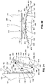
- the vertical beam top portion 154 of each vertical beam 152 is operably engaged (e.g., Figure 13 ) to the horizontal drive motor 136 for driving the vertical beam assembly 150 along the horizontal drive axis 134.
- Each vertical beam assembly 150 further includes a vertical drive mechanism 162 mounted to the vertical beam 152.
- the vertical beam 152 drive mechanism has a vertical drive motor 170 and a vertical beam track system 166 which defines a vertical drive axis 168 (e.g., Figures 14-15 ).
- Each vertical beam assembly 150 further includes a workpiece attachment assembly 200 which is coupled to the vertical beam track system 166 (e.g., Figures 15-16 and 18 ) and is operably engaged (e.g., Figure 18 ) to the vertical drive motor 170 for driving the workpiece attachment assembly 200 along the vertical drive axis 168.
- each workpiece attachment assembly 200 includes an attachment mechanism 202 (e.g., Figures 17-18 ) configured to be removably attached to one of opposing workpiece side portions 406 of a workpiece 400 supported on the manufacturing fixture 500.
- the workpiece 400 may have an inner surface geometry 410 (e.g., Figures 5-6 ) that may be engaged to the fixture outer surface 502 (e.g., Figures 3-4 ) of the manufacturing fixture 500.
- the inner surface geometry 410 may include one or more protrusions 412 (e.g., Figures 5-6 ) that may be received within one or more depressions 508 (e.g., Figures 3-4 ) that may be formed in the fixture outer surface 502 of the manufacturing fixture 500.
- the workpiece may have an inner surface geometry that may include one or more depressions (not shown) that may be configured to receive one or more protrusions (not shown) that may protrude outwardly from the fixture outer surface of a manufacturing fixture.
- the workpiece 400 and/or the manufacturing fixture 500 may have protrusions 412 and/or depressions 508, the engagement of the protrusions 412 with the depressions 508 may interfere with removal of the workpiece 400 from the manufacturing fixture 500.
- the workpiece 400 and/or the manufacturing fixture 500 may be devoid of protrusions 412 and/or depressions 508.
- the geometry of the workpiece 400 and/or the geometry of the manufacturing fixture 500 may interfere with the removal of the workpiece 400 from the manufacturing fixture 500.
- the workpiece 400 may have a concave shape that may prevent removal of the workpiece 400 from a convexly-shaped manufacturing fixture upon which the workpiece 400 is supported.
- the one or more horizontal drive motors 136 of the horizontal beam assemblies and the vertical drive motors 170 respectively of the vertical beam assemblies 150 are configured to be operated in a coordinated manner to move the vertical beams 152 away from each other (using the horizontal drive motors 136) along the horizontal drive axis 134 while simultaneously moving the workpiece attachment assemblies 200 along the corresponding vertical drive axes 168 (using the vertical drive motors 170) to cause the attachment mechanisms 202 on each side of the workpiece 400 to pull the workpiece side portions 406 away from the manufacturing fixture 500 while the center support 114 of the horizontal beam 110 maintains the workpiece crown 416 in contact with the manufacturing fixture 500, as shown in Figures 22-25 and described in greater detail below.
- the coordinated operation of the horizontal drive motors 136 and vertical drive motors 170 causes the workpiece attachment assemblies 200 to spread apart the workpiece side portions 406 such that the workpiece 400 transitions from an undeflected state 612 (e.g., Figure 20-21 ) to a deflected state 614 (e.g., Figures 23-24 ) while the center support 114 maintains the workpiece crown 416 in contact with the manufacturing fixture 500 (e.g., Figure 22 ).
- the center portion prevents the workpiece crown 416 from lifting off of the manufacturing fixture 500 during outward deflection of the workpiece side portions 406.
- the center support 114 defines the center of rotation 604 ( Figures 22-23 ) about which the workpiece side portions 406 are outwardly deflected.
- the movement of the workpiece attachment assemblies 200 may outwardly deflect the workpiece side portions 406 at least until a clearance (e.g., shown exaggerated in Figures 23-24 ) exists between the workpiece side portion 406 and the fixture outer surface 502 on each of opposing sides of the manufacturing fixture 500.
- the workpiece side portions 406 may be outwardly deflected by an amount that allows for separation and/or translation of the workpiece 400 away from the manufacturing fixture 500 as shown in Figure 25 and described in greater detail below.
- the removal of the workpiece 400 from the manufacturing fixture 500 may be performed while the horizontal drive mechanism 126 and vertical drive mechanisms 162 are inactive and the vertical beam assemblies 150 and the workpiece attachment assemblies 200 are stationary.
- the horizontal drive mechanisms 126 and vertical drive mechanisms 162 may be operated in a manner to reverse the direction of the vertical beam assemblies 150 and workpiece attachment assemblies 200 in a manner to move the workpiece side portions 406 back to their initial positions 608 such that the workpiece 400 returns to the undeflected state 612 (e.g., Figures 20-21 ), at which point the workpiece 400 may be loaded onto a support fixture (not shown) and the attachment mechanisms 202 of the flay system 100 may be released from the workpiece 400.
- FIG. 2-6 shown is an example of a manufacturing fixture 500 configured as a layup mandrel 504 for supporting a workpiece 400 configured as a cured composite skin panel 450.
- the presently-disclosed flay system 100 is described in the context of removing the composite skin panel 450 from the layup mandrel 504.
- Figure 2 shows an example of the layup mandrel 504 upon which the skin panel 450 may be laid up and cured.
- the layup mandrel 504 may have a mandrel body 506 that is monolithic (i.e., one-piece) and which is supported by a pair of end rings 514. Each one of the end rings 514 may be supported on a fixture base 516.
- the fixture base 516 may include a ring cradle 518 at each end of the mandrel body 506 for rotatably supporting the mandrel body 506.
- the layup mandrel 504 may include one or more rotator motors 520 for rotating the mandrel body 506 during layup of the composite skin panel 450.
- the mandrel body 506 may include a plurality of depressions 508 or grooves 510 oriented along a lengthwise direction of the layup mandrel 504. Each one of the grooves 510 may be configured to receive an uncured or precured composite stringer which may be separately laid up on a stringer layup tool (not shown) prior to installation of the stringers 454 within the grooves 510.
- the stringers 454 may have a cross-sectional shape that is square, rectangular, triangular, semi-circular, or any one of a variety of other cross-sectional shapes.
- one or more plies of composite material may be laid up over the stringers 454 and mandrel outer surface 512 to form the skin element 452.
- the layup mandrel 504 may be rotated (e.g., via the rotator motors 520) during the application of unidirectional composite tape (not shown) over the stringers 454 and mandrel outer surface 512 to form an uncured composite barrel section (not shown).
- the layup mandrel 504 may then be moved into an autoclave (not shown) for co-curing or co-bonding of the skin element 452 and stringers 454 at an elevated temperature and/or pressure to form a cured composite barrel section having a generally cylindrical shape.
- the cured composite barrel section may be cut along a lengthwise direction on each of diametrically opposite sides of the layup mandrel 504 to form a pair of skin panels 450 each having a generally semi-cylindrical shape.
- Figure 3 is a perspective view of the layup mandrel 504 showing one of the skin panels 450 having a semi-cylindrical shape supported on the layup mandrel 504.
- Figure 4 is an end view of the layup mandrel 504 showing the skin panel 450 stringers 454 nested within the grooves 510 in the mandrel body 506.
- Figures 5-6 show the skin panel 450 separated from the layup mandrel 504 and illustrating the stringers 454 protruding inwardly the skin inner surface of the skin panel 450.
- a plurality of the skin panels 450 may be assembled to form a fuselage of an aircraft (not shown).
- the cured skin panel 450 may be relatively stiff and resistant to deflection in the out-of-plane direction.
- the flay system 100 advantageously may be operated in a manner to upwardly deflect the opposing workpiece side portions 406 of the skin panel 450 in a controlled manner along a predetermined deflection path and at a predetermined deflection rate.
- the flay system 100 advantageously provides the ability for recording a time-history of the outward deflection of the workpiece side portions 406 to facilitate a determination that the deflection of the workpiece 400 was performed within predetermined engineering limits, thereby avoiding time-consuming inspection of the skin panel 450 that would otherwise be required if the deflection characteristics (e.g., deflection magnitude, deflection rate and/or deflection movement path) were unknown.
- the skin panel 450 is generally symmetrical about a workpiece vertical centerline 404 which may dictate operating the flay system 100 in a manner to outwardly deflect the opposing workpiece side portions 406 of the skin panel 450 by equal amounts.
- the presently-disclosed flay system 100 may be implemented on workpieces (not shown) that are non-symmetrical about the workpiece vertical centerline 404.
- the flay system 100 may be operated in a manner to outwardly deflect the workpiece side portion 406 on one side of a workpiece 400 at a different deflection magnitude, rate and/or movement path than the workpiece side portion 406 on an opposite side of the workpiece 400.
- Figure 7 shows an example of a flay system 100 positioned over a layup mandrel 504 for removing the skin panel 450 from the layup mandrel 504.
- the flay system 100 includes a plurality of flay assemblies 102 (e.g., Figure 10 ) arranged in spaced relation to each other.
- the flay system 100 is shown having a support system 300 configured as a floor stand 302 for supporting the plurality of flay assemblies 102 over the layup mandrel 504.
- the floor stand 302 is made up of a framework of horizontal support beams 310 and vertical support posts 306.
- the floor stand 302 may further include a plurality of angled support legs 308 and diagonal braces 312 for laterally supporting the vertical support posts 306.
- the vertical support posts 306 are interconnected by the horizontal support beams 310.
- the plurality of flay assemblies 102 may be attached to the horizontal support beams 310 via a backbone frame 104.
- FIG 8 is a front view of the flay system 100 of Figure 7 showing the floor stand 302 supporting the flay system 100 over the layup mandrel 504. Also shown is one of the flay assemblies 102 coupled to the skin panel 450 which is supported on the manufacturing fixture 500. As mentioned above, each one of the flay assemblies 102 includes a horizontal beam assembly 108 and a pair of vertical beam assemblies 150 which are mounted in spaced relation to the horizontal beam assembly 108. As described in greater detail below, each one of the vertical beam assemblies 150 is movable along the horizontal beam 110 in coordination with movement of the workpiece attachment assemblies 200 respectively along the pair of vertical beams 152 as a means for outwardly deflecting the workpiece side portions 406 of the skin panel 450.
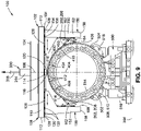
- Figure 9 is a front view of an example of a flay system 100 supported by a support system 300 configured as a longitudinal beam 314.
- the longitudinal beam 314 is configured to suspend the flay system 100 from a hoist cable 316.
- the hoist cable 316 may extend downwardly from an overhead beam (not shown) of a production facility.
- the longitudinal beam 314 may be suspended from a hoist cable 316 extending downwardly from a mobile crane (not shown).
- the longitudinal beam 314 may extend along the length of the flay system 100 and may be interconnected to the individual flay assemblies 102 by a backbone frame 104.
- Figure 10 shows an example of a flay system 100 having a plurality of flay assemblies 102 interconnected by a backbone frame 104.
- the backbone frame 104 may include one or more longitudinally extending beams and one or more laterally extending beams to form a rigid structure that is preferably resistant to twisting and/or deformation during operation of the flay system 100.
- the quantity of flay assemblies 102 that are included with a flay system 100 may be based on the largest size of a workpiece 400 for which the flay system 100 may be implemented.
- a flay system 100 may be operated such that any number of the flay assemblies 102 may be actively involved in the removal of a workpiece 400 from a manufacturing fixture 500 while one or more of the flay assemblies 102 are inactive.
- each flay assembly 102 in the flay system 100 is shown as being identically configured which may simplify manufacturing and assembly of the flay system 100 and may reduce operational complexity. However, in examples not shown, a flay system 100 may have one or more flay assemblies 102 that are configured differently than other flay assemblies 102 in the flay system 100.
- FIG 11 shown in Figure 11 is a front view of a portion of a horizontal beam assembly 108 and one of the vertical beam assemblies 150 coupled to the horizontal beam assembly 108.
- the figures of the present disclosure illustrate the vertical beams 152 as being oriented generally perpendicular to the horizontal beam 110 (e.g., Figures 8-11 ), the vertical beams 152 may be oriented at a non-perpendicular angle relative to the horizontal beam 110.
- the terms "horizontal” and “vertical” are descriptive with regard to the orientation of the flay system 100 components relative to each other for the example flay system 100 shown in the figures, and do not limit the use of the flay system 100 in orientations where the components labelled as horizontal and vertical are respectively non-horizontal and non-vertical.
- the flay system 100 may be rotated 90 degrees about a longitudinal axis 402 of a workpiece 400 during removal of the workpiece 400 from a manufacturing fixture 500, and resulting in the horizontal beam 110 being oriented vertically and the vertical beams 152 being oriented horizontally during the workpiece 400 removal process including during outward deflection of the workpiece side portions 406.
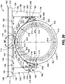
- the horizontal beam 110 has a center support 114 configured to be placed in contact with the workpiece crown 416 as shown in Figures 20 and 22 .
- the center support 114 may be coupled to an underside of the horizontal beam 110 and may be centered between the opposing horizontal beam ends 112. In this regard, the center support 114 may be centered on the flay assembly vertical centerline 106.
- the center support 114 may be an integral part of the horizontal beam 110 such as a discrete area (not shown) on the underside or lower surface of the horizontal beam 110.
- the horizontal drive mechanism 126 including the horizontal drive motor 136 and horizontal drive shaft 138 is located in an interior (not shown) of the horizontal beam 110 or on a side of the horizontal beam 110 to avoid interfering with the workpiece 400 during contact of the center support 114 to the workpiece crown 416.
- the horizontal beam assembly 108 includes at least one horizontal drive mechanism 126 configured to move the vertical beam assemblies 150 along the horizontal drive axis 134.
- each horizontal beam assembly 108 includes a pair of horizontal drive mechanisms 126 respectively located on opposite sides of the flay assembly vertical centerline 106.
- the horizontal beam assembly 108 further includes at least one horizontal beam track system 128.
- a horizontal beam track system 128 may be mounted to the horizontal beam 110 on each of opposing sides of the flay assembly vertical centerline 106.
- Each one of the horizontal beam track systems 128 may include at least one set of guide tracks 130 mounted to the horizontal beam 110.
- a pair of guide tracks 130 may be mounted to the horizontal beam 110 on each side of the flay assembly vertical centerline 106.
- the guide tracks 130 may be fixedly coupled to the underside of the horizontal beam 110 and may extend along a lengthwise direction of the horizontal beam 110 as shown in Figures 11 and 13 .
- the horizontal beam track system 128 defines the horizontal drive axis 134 which extends along the lengthwise direction of the horizontal beam 110 between opposing horizontal beam ends 112.
- each one of the vertical beams 152 has a vertical beam top portion 154 and a vertical beam bottom portion 158.
- Each vertical beam top portion 154 is coupled to the horizontal beam track system 128 by one or more pairs of top portion brackets 156 of the vertical beam top portion 154.
- each top portion bracket 156 may include a linear bearing 132 configured to be slidably coupled to one of the guide tracks 130 of the horizontal beam track system 128.
- the vertical beam assemblies 150 are driven along the horizontal drive axis 134 by one or more horizontal drive motors 136.
- Each horizontal drive motor 136 may include a horizontal drive shaft 138 rotatably driven by the horizontal drive motor 136.
- the horizontal drive shaft 138 may be configured as a threaded shaft 140 such as a lead screw or a ball screw.
- the vertical beam top portion 154 of each one of the vertical beams 152 may be operably engaged to the horizontal drive shaft 138 for driving the vertical beams 152 assembly along the horizontal drive axis 134.
- each vertical beam top portion 154 may have a drive fitting 160 (e.g., Figure 13 ) coupled to a nut 142 (e.g., Figure 13 ) that is threadably engaged to the threaded shaft 140.
- the horizontal drive motor 136 may be provided as a servo motor for rotating the threaded shaft 140 for driving the vertical beam assembly 150 linearly along the horizontal drive axis 134.
- the horizontal drive motor 136 may be provided as a brushless direct current (DC) servo motor coupled to the threaded shaft 140 via a gearbox (not shown) such as a planetary gearbox.
- a rotary encoder 144 such as a 12-bit rotary encoder may be operably coupled to the horizontal drive motor 136 for measuring angular motion of the threaded shaft 140.
- each horizontal beam assembly 108 may include a single horizontal drive motor 136 configured to rotate a single threaded shaft 140 to which both of the vertical beam assemblies 150 are operably engaged.
- the portion of the threaded shaft 140 on one side of the flay assembly vertical centerline 106 may have left-hand threads (not shown) to which a nut 142 is threadably engaged, and the portion of the threaded shaft 140 on the opposite side of the flay assembly vertical centerline 106 may have right-hand threads (not shown) to which a nut 142 is threadably engaged, and resulting in the vertical beam assemblies 150 moving in opposite directions during rotation of the threaded shaft 140 by a single one of the horizontal drive motors 136.
- each horizontal beam assembly 108 may include a pair of horizontal drive motors 136 respectively located on opposite sides of the flay assembly vertical centerline 106 and each configured to independently rotate a threaded shaft 140 respectively coupled to the horizontal drive motors 136.
- the vertical drive motors 170 may be operated in a synchronized manner for equal and opposite motion of the respective vertical beam assemblies 150 along the horizontal drive axis 134.
- each vertical beam assembly 150 includes a vertical drive mechanism 162 mounted to the vertical beam 152.
- the vertical drive mechanism 162 includes a vertical beam track system 166 defining a vertical drive axis 168.
- the vertical beam track system 166 of each one of vertical drive mechanisms 162 may include a pair of guide tracks 130 fixedly coupled to the vertical beam 152 and extending along a lengthwise direction of the vertical beam 152.
- the vertical beam track system 166 defines the vertical drive axis 168 which is oriented parallel to the lengthwise direction of the vertical beam 152.
- the workpiece attachment assembly 200 is coupled to the vertical beam track system 166.
- the workpiece attachment assembly 200 may include an attachment block 210 that may be coupled to the pair of guide tracks 130 via linear bearings 132.
- each vertical drive mechanism 162 includes a vertical drive motor 170 coupled to a vertical drive shaft 172 rotatably driven by the vertical drive motor 170.
- the vertical drive mechanism 162 may be configured similar to the above-described horizontal drive mechanism 126.
- the vertical drive shaft 172 may be a threaded shaft 140 having a nut 142 engaged to the threaded shaft 140.
- the vertical drive motor 170 may be provided as an electric motor such as a brushless DC servo motor.
- Each vertical assembly includes a workpiece attachment assembly 200 that is operably engaged to the vertical drive shaft 172 for driving the workpiece attachment assembly 200 along the vertical drive axis 168.
- the attachment block 210 may include a drive fitting 160 fixedly coupled to a nut 142 that is threadably engaged to the threaded shaft 140 of the vertical drive mechanism 162. Rotation of the threaded shaft 140 by the vertical drive motor 170 causes corresponding linear motion of the workpiece attachment assembly 200 along the vertical drive axis 168.
- the vertical drive mechanism 162 may include a pair of linearly expandable bellows 164 located on upper and lower sides of the attachment block 210 for protection of the linear bearings 132, guide tracks 130, threaded shaft 140, nut 142, and drive fitting 160 from dust, dirt, and other contaminants.
- the horizontal drive mechanism 126 and vertical drive mechanism 162 are each described as having a nut 142 threadably engaged to a threaded shaft 140 for converting rotary motion of the horizontal drive motor 136 and vertical drive motor 170 into linear motion respectively of the vertical beam assemblies 150 and workpiece attachment assemblies 200
- the horizontal drive mechanism 126 and/or the vertical drive mechanism 162 may alternatively be configured as a rack-and-pinion drive system (not shown), a belt drive system (not shown), or any one a variety of other drive systems capable of driving the vertical beam assemblies 150 and workpiece attachment assemblies 200 respectively along the horizontal drive axis 134 and vertical drive axes 168.
- the horizontal drive mechanisms 126 and the vertical drive mechanisms 162 are not limited to the examples shown and described.
- the workpiece attachment assembly 200 includes the attachment mechanism 202 which is configured to be removably attached to one of opposing workpiece side portions 406 (e.g., Figure 20 ) of a workpiece 400 supported on a manufacturing fixture 500 underlying the workpiece 400.
- the workpiece 400 may have a workpiece inner surface 408 having an inner surface geometry 410 that may be supported on the fixture outer surface 502 of the manufacturing fixture 500.
- the inner surface geometry 410 of the workpiece 400 may prevent removal of the workpiece 400 from the manufacturing fixture 500.
- the stringers 454 e.g., protrusions 412 of a skin panel 450 may be nested within the grooves 510 (e.g., depressions 508) of a layup mandrel 504 and which may prevent removal of the skin panel 450 from the layup mandrel 504.
- the attachment mechanism 202 may include one or more vacuum plates 208 each having one or more vacuum cups (not shown).
- each vacuum plate 208 may include an array of vacuum cups (not shown) fluidly coupled to a vacuum source (not shown).
- the vacuum source may comprise a vacuum pump which may be mounted on the flay system 100.
- the array of vacuum cups of each vacuum plate 208 may be multi-chambered in which sets of one or more vacuum cups of each vacuum plate 208 are independently fluidly coupled to the vacuum source for redundancy in the event of a loss of vacuum pressure at one or more of the vacuum cups.
- Each vacuum plate 208 may have a length-to-width aspect ratio of greater than 1.
- the length of the vacuum plate 208 may be oriented generally parallel to a lengthwise direction (e.g., axial direction) of the workpiece 400. However, the vacuum plate 208 may have a length-to-width aspect ratio equal to or less than 1.
- the workpiece attachment assembly 200 of each vertical beam assembly 150 may include an attachment assembly pivot joint 212 pivotably coupling the attachment mechanism 202 to the vertical drive mechanism 162.
- the attachment assembly pivot joint 212 may be provided as a pseudo-spherical joint configured to limit movement of the attachment mechanism 202 to pivoting about a roll axis 214 and optionally about a yaw axis 216.
- the roll axis 214 may be oriented orthogonal to the vertical drive axis 168 and orthogonal to the horizontal drive axis 134.
- the yaw axis 216 may be oriented approximately parallel to the vertical drive axis 168.
- the attachment mechanisms 202 may pivot about the roll axis 214 and/or the yaw axis 216 of the attachment assembly pivot joint 212 to facilitate attachment of the attachment mechanism 202 to the workpiece side portions 406 and/or to allow free movement of the attachment mechanisms 202 relative to the vertical drive mechanism 162 during outward deflection of the workpiece side portions 406.
- Configuring the attachment assembly pivot joints 212 for pivoting motion about the roll axis 214 and yaw axis 216 allows the attachment mechanisms 202 to self-orient in a manner such that the attachment mechanisms 202 are locally tangent to the workpiece outer surface 414 during engagement of the attachment mechanism 202 to the workpiece side portion 406.
- free pivoting of the attachment mechanisms 202 about the roll axis 214 and yaw axis 216 reduces or prevents torque loads in the workpiece attachment assembly 200 and/or in the workpiece 400 that would otherwise be generated during deflection of the workpiece side portions 406 if the attachment mechanisms 202 were prevented from pivoting about the role axis and yaw axis 216 such as during outward deflection of the workpiece side portions 406.
- the attachment assembly pivot joint 212 may be configured to prevent pivoting of the attachment mechanisms 202 about a pitch axis (not shown) at least during the initial engagement of the attachment mechanisms 202 to the workpiece side portions 406.
- the pitch axis may be oriented orthogonal to both the roll axis 214 and the yaw axis 216. Preventing pivoting of the attachment mechanisms 202 about a pitch axis may maintain the attachment mechanisms 202 in alignment with the lengthwise direction of the workpiece 400.
- the attachment mechanisms 202 are configured as vacuum plates 208
- preventing pivoting of the vacuum plates 208 about the pitch axis prevents the vacuum plates 208 from contacting the workpiece outer surface 414 in a skewed orientation non-parallel to the longitudinal axis 402 of the workpiece 400 (e.g., a skin panel 450 that is semi-cylindrical), and which may prevent one or more of the vacuum cups of the vacuum plate 208 from forming a vacuum-tight seal against the workpiece outer surface 414 of the skin panel 450.
- the flay system 100 may be configured such that the attachment mechanisms 202 of some of the flay assemblies 102 are limited to pivoting about a roll axis 214, and other flay assemblies 102 of the same flay system 100 allow for pivoting about both the roll axis 214 and the yaw axis 216.
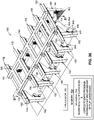
- the three (3) flay assemblies 102 located on the left-hand side of Figure 27 that interface with the constant cylindrical cross-section portion of the skin panel 450 may require pivoting of the attachment assemblies about only the roll axis 214 to allow the attachment mechanisms 202 (e.g., vacuum plates 208) to self-align with the cylindrical shape of the skin panel 450.
- the three (3) flay assemblies 102 located on the right-hand side of Figure 27 that interface with the variable cross-section / compound curvature portion of the skin panel 450 may require pivoting about both the roll axis 214 and the yaw axis 216 to allow the attachment mechanisms 202 to self-align into a tangent orientation with the compound curvature of the skin panel 450.
- each attachment mechanism 202 may include a pair of the vacuum plates 208 respectively coupled to a pair of pivot arms 206 of a pivot bracket 204 pivotably coupled by an attachment assembly pivot joint 212 to the vertical drive mechanism 162.
- Each one of the vacuum plates 208 may be mounted to a free end of a pivot arm 206 in a manner limiting movement of the vacuum plate 208 to pivoting motion about the roll axis 214 of the pivot arm 206.
- the attachment assembly pivot joint 212 and/or the pivot joints at the free end of each pivot arm 206 may facilitate engagement of the vacuum cups of the vacuum plates 208 to the workpiece outer surface 414.
- an attachment mechanism 202 is not limited to vacuum plates 208 and may include any one a variety of other types of attachment mechanisms 202 capable of coupling the workpiece attachment assembly 200 to the workpiece side portions 406.
- an attachment mechanism 202 may be configured as a mechanical attachment device (not shown) for mechanically coupling to a workpiece side portion 406.
- an attachment mechanism 202 may include one or more threaded fasteners configured to be threadably engaged (e.g., manually or via a remotely-controlled screw drive mechanism) to a threaded receptacle (e.g., an internally-threaded insert, a nutplate, etc.) that may be pre-installed on the workpiece 400.
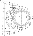
- FIG. 19 shown is an example of the flay system 100 positioned above a manufacturing fixture 500 configured as a layup mandrel 504 supporting a workpiece 400 configured as a skin panel 450.
- the manufacturing fixture 500 is shown being vertically raised into position for engagement with the flay system 100.
- the flay system 100 may be lowered into engagement with the manufacturing fixture 500.
- the horizontal drive motor 136 and vertical drive motors 170 Prior to engagement of the flay system 100 to the workpiece 400, the horizontal drive motor 136 and vertical drive motors 170 may be operated in a manner to locate each one of the attachment mechanisms 202 at a pre-attachment position 606 in preparation for coupling the attachment mechanisms 202 respectively to the workpiece side portions 406.
- the horizontal drive motors 136 may be operated in a manner to horizontally space the vertical beam assemblies 150 apart from each other at a distance that provides clearance between each attachment mechanism 202 and the corresponding one of the workpiece side portions 406.
- the vertical drive motors 170 may be operated in a manner to vertically position each one of the workpiece attachment assemblies 200 at a vertical location where the attachment mechanisms 202 will be coupled to the workpiece side portions 406 when the center support 114 is in contact with the workpiece crown 416.
- the flay system 100 engaged to the workpiece 400 which is supported in an undeflected state 612 on the manufacturing fixture 500.
- the horizontal drive motors 136 may have been activated to move the vertical beam assemblies 150 toward each other for moving the pair of attachment mechanisms 202 (e.g., vacuum plates 208) from the pre-attachment position 606 ( Figure 19 ) to an initial position 608 ( Figure 20 ) at which the attachment mechanisms 202 are engaged to or are in contact with the workpiece side portions 406.
- the pair of attachment mechanisms 202 e.g., vacuum plates 208
- the vacuum source may be activated to cause vacuum sealing of the vacuum cups (not shown) of the vacuum plates 208 to the workpiece outer surface 414 at the workpiece side portions 406.
- Figure 21 is a magnified view of a portion of the vertical beam assembly 150 showing one of the attachment mechanisms 202 configured as a pair of vacuum plates 208 attached to one of the workpiece side portions 406.
- the vacuum plates 208 may self-orient into alignment with the workpiece outer surface 414 by pivoting capability of each vacuum plate 208 respectively at least about the roll axis 214 at the free end of each pivot arm 206.
- attachment assembly pivot joint 212 which allows pivoting of the attachment mechanism 202 about the roll axis 214 and also optionally about the yaw axis 216 of the attachment assembly pivot joint 212.
- Figure 22 is a magnified view of a portion of the horizontal beam assembly 108 showing the center support 114 of the horizontal beam 110 in contact with the workpiece outer surface 414.
- the center support 114 may be centered between the pair of vertical beam assemblies 150 and functions as a center of rotation 604 about which the attachment mechanisms 202 are moved during outward deflection of the workpiece side portions 406, as described in greater detail below.
- the center support 114 may be located at a flay assembly vertical centerline 106 which may be located at a mid-point between the pair of vertical beam assemblies 150.
- the center support 114 may have at least one support pad 120 extending outwardly from the horizontal beam 110 and configured to be locally tangent to the workpiece outer surface 414 at the workpiece crown 416.
- the center support 114 includes a pair of support pads 120 which may each be configured to be locally tangent to the workpiece outer surface 414 at the workpiece crown 416 when the workpiece attachment assemblies 200 are attached respectively to the opposing workpiece side portions 406.
- each one of the support pads 120 may be pivotable about a pad pivot axis 124 to allow for self-orientation of the pivot pads into tangent relation to the workpiece outer surface 414 as the support pad 120 is moved into contact with the workpiece crown 416.
- the support pads 120 may maintain the workpiece inner surface 408 in contact with the fixture outer surface 502 at the workpiece crown 416 during outward deflection of the opposing workpiece side portions 406.
- the support pads 120 may include one or more vacuum cups to allow the support pads 120 to be releasably attached to the workpiece crown 416 to assist the vacuum plates 208 on the opposing workpiece side portions 406 in supporting the mass of the workpiece 400 such as during separation and/or translation of the manufacturing fixture 500 away from the workpiece 400 as shown in Figure 25 and described in greater detail below.
- the center support 114 may include a center support block 116 mounted to the horizontal beam 110.
- the horizontal drive shaft 138 may optionally extend through the center support block 116.
- the center support block 116 may include a pair of center support shafts 118 extending vertically downwardly from the center support block 116.
- a pair of the support pads 120 may be arranged in side-by-side relation and mounted respectively to the free ends of the pair of center support shafts 118.
- the center support shafts 118 may be vertically adjustable to allow for adjusting the vertical position of the support pads 120 for positioning into contact with the workpiece outer surface 414 for a workpiece 400 in which the distance from the workpiece crown 416 to the horizontal beam 110 varies along the longitudinal axis 402 of the workpiece 400.
- the skin panel 450 shown in Figures 26-27 has a semi-cylindrical shape that tapers in diameter along the longitudinal axis 402 (e.g., axial centerline) of the skin panel 450.
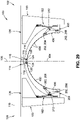
- the taper in the diameter of the skin panel 450 results in variations in the distance between the workpiece crown 416 and the horizontal beam 110 of a flay assembly 102 at one end of the flay system 100 ( Figure 20 ) relative to the distance between the workpiece crown 416 and the horizontal beam 110 of a flay assembly 102 at an opposite end of the flay system 100 ( Figure 29 ).
- the center support shafts 118 the vertical position of the support pads 120 may be adjusted such that the support pads 120 of each flay assembly 102 contact the workpiece crown 416.
- each support pad 120 may have a pad surface 122 configured to be tangent to the workpiece outer surface 414 proximate the workpiece crown 416 (e.g., at the workpiece vertical centerline 404).
- each one of the support pads 120 may be pivotably coupled (via a pad pivot axis 124) to the end of the center support shaft 118 to allow the pad surface 122 to self-orient until locally tangent to the workpiece outer surface 414 at the workpiece crown 416 during initial engagement of the support pads 120 with the workpiece outer surface 414 as the manufacturing fixture 500 is vertically moved into engagement with the flay system 100 (e.g., Figure 19 ).
- each one of the support pads 120 of the center support 114 maintains the workpiece inner surface 408 in contact with the fixture outer surface 502 at the workpiece crown 416 during outward deflection of the workpiece side portions 406, which may otherwise have a tendency to vertically lift off the workpiece 400 during outward deflection of the workpiece side portions 406.
- FIG. 23-24 shown is a front view of the flay assembly 102 illustrating the workpiece side portions 406 after being outwardly deflected by the attachment mechanisms 202 as a result of coordinated movement of the vertical beam assemblies 150 and workpiece attachment assemblies 200.
- the horizontal drive motors 136 and the vertical drive motors 170 of each flay assembly 102 in the flay system 100 are operable in a coordinated manner to simultaneously move the vertical beams 152 of each flay assembly 102 away from each other along the horizontal drive axis 134 while moving each workpiece attachment assembly 200 (e.g., upwardly toward the horizontal beam) along the vertical drive axis 168 in a manner causing the attachment mechanisms 202 to pull the workpiece side portions 406 away from the manufacturing fixture 500.
- the movement of the attachment assemblies causes the workpiece side portions 406 to spread apart while the center support 114 of the horizontal beam 110 maintains the workpiece crown 416 in contact with the manufacturing fixture 500.
- the center support 114 functions as the point of rotation about which the workpiece side portions 406 are deflected.
- the horizontal drive motors 136 and the vertical drive motors 170 may be operated in a coordinated manner to outwardly deflect the workpiece side portions 406 along a specific movement path such as an arcuate movement path.
- the movement path along which the workpiece side portions 406 are outwardly deflected may be defined relative to a specific point or feature on each workpiece attachment assembly 200.
- the horizontal drive motors 136 and the vertical drive motors 170 of each flay assembly 102 may be operated in a manner causing the attachment assembly pivot joint 212 of each one of the workpiece attachment assemblies 200 to simultaneously move outwardly along a deflection arc 600 of constant radius generally centered at the center support 114 which functions as the center of rotation 604.
- the center of rotation 604 may be located proximate the intersection of the workpiece inner surface 408 and a vertical plane (not shown) coincident with the longitudinal axis 402 (e.g., an axial centerline) of the workpiece 400 (e.g., a skin panel 450).
- the attachment mechanisms 202 of the pair of vertical beams assemblies on opposite sides of the manufacturing fixture 500 may be moved along the same arc length 616 ( Figures 23-24 ) from the initial position 608 (workpiece 400 in the undeflected state 612 - Figures 20-21 ) to a final position 610 in which the workpiece 400 is in a deflected state 614 as shown in Figures 23-24 .
- the horizontal drive motors 136 and the vertical drive motors 170 may be operated according to a numerical control (NC) program executed by a processor 700 communicatively coupled to the horizontal drive motors 136 and the vertical drive motors 170.
- the horizontal drive motors 136 and the vertical drive motors 170 may be controlled by the processor 700 to simultaneously outwardly deflect the workpiece side portions 406 by equal amounts away from the fixture outer surface 502 and at the same deflection rate.
- the workpiece side portions 406 may be simultaneously deflected outwardly at least until clearance (shown exaggerated in Figures 23-24 ) exists between the workpiece inner surface 408 and the fixture outer surface 502 on each side of the manufacturing fixture 500 to allow for removal of the workpiece 400 from the manufacturing fixture 500.
- the manufacturing fixture 500 may be moved (e.g., lowered) away from the flay system 100 and/or the flay system 100 may be moved (e.g., raised) away from the manufacturing fixture 500 as shown in Figure 25 .
- the horizontal drive mechanisms 126 and vertical drive mechanisms 162 may be operated in a manner to reverse the direction of the vertical beam assemblies 150 and workpiece attachment assemblies 200 in a manner to move the attachment mechanisms 202 from the final position 610 (workpiece 400 in the deflected state 614 - Figures 23-25 ) to the initial position 608 (workpiece 400 in the undeflected state 612 - Figures 20-21 ).
- the flay system 100 may load the workpiece 400 onto a support fixture (not shown) after which the attachment mechanisms 202 may be released from the workpiece side portions 406 allowing the flay system 100 to be transported away.
- the flay system 100 may include the above-mentioned processor 700 configured to control the horizontal drive motors 136 and the vertical drive motors 170.
- the flay system 100 may additionally include a memory 702 communicatively coupled to the processor 700 and configured to store a database 704 of workpiece configurations and corresponding program files. For each workpiece configuration, the corresponding program file defines the movement profile of the attachment mechanisms 202 in the flay system 100.
- Each program file may be configured as a numerical control program that is executable by the processor 700 for commanding the horizontal drive motors 136 and vertical drive motors 170 of the flay system 100 in a manner to control the positions and movements of the attachment mechanisms 202 of all of the flay assemblies 102 that are involved in the removal of a workpiece 400 from a manufacturing fixture 500.
- Each movement profile defines the positions of the attachment mechanisms 202 during different stages of the removal process such as the pre-attachment position 606 of the attachment mechanisms 202 (e.g., Figure 19 ), the initial position 608 (e.g., Figure 20-22 ) of the attachment mechanisms 202 when the workpiece 400 is in the undeflected state 612 and is supported on the manufacturing fixture 500, and the final position 610 (e.g., Figure 23-24 ) of the attachment mechanisms 202 when the workpiece 400 is in the deflected state 614 after outward deflection of the workpiece side portions 406.
- the pre-attachment position 606 of the attachment mechanisms 202 e.g., Figure 19
- the initial position 608 e.g., Figure 20-22
- the final position 610 e.g., Figure 23-24
- each movement profile defines the directional path of the attachment mechanisms 202 during movement of the attachment mechanisms 202 from the initial position 608 to the final position 610.
- the movement path may be defined as a deflection arc 600 centered approximately at the center support 114.
- the positions of the attachment mechanisms 202 may be defined in terms of the lateral distance of each attachment mechanism 202 from the flay assembly vertical centerline 106 and the vertical distance of each attachment mechanism 202 from the horizontal beam 110.
- the program file defines the manner in which the processor 700 controls the horizontal drive motors 136 and vertical drive motors 170 for moving the vertical beam assemblies 150 relative to the horizontal beam 110 and for moving the workpiece attachment assemblies 200 relative to the vertical beam assemblies 150 to achieve the defined positions and movements of the attachment mechanisms 202.
- each program file may define the movement rates of the vertical beam assemblies 150 along the horizontal beam assembly 108 and the movement rates of each workpiece attachment assembly 200 along the vertical beam assembly 150, to achieve a desired movement rate of each attachment mechanism 202 along the movement path (e.g., deflection arc 600).
- the processor 700 may control the flay assemblies 102 in a synchronized manner.
- the processor 700 may command the horizontal drive motors 136 and vertical drive motors 170 of all flay assemblies 102 in the flay system 100 to initiate movement of the attachment mechanisms 202 to start outward deflection of the workpiece side portion 406 at each flay assembly 102 at approximately the same time (e.g., within several second of each other) at the initial position 608, and to move the attachment mechanisms 202 at approximately the same rate (e.g., within approximately 10 percent of each other), and to stop the attachment mechanisms 202 at approximately the same time (e.g., within several second of each other) at the final position 610.
- the processor 700 may command the horizontal drive motors 136 and vertical drive motors 170 of all flay assemblies 102 in the flay system 100 to initiate movement of the attachment mechanisms 202 to start outward deflection of the workpiece side portion 406 at each flay assembly 102 at approximately the same time (e.g., within several second of each other) at the initial position 608, and to move the attachment mechanisms 202 at approximately the same rate (e.g.
- the radius of the deflection arc 600 defined by the program file for each flay assembly 102 may be proportional to the local radius of curvature 602 of the workpiece 400 at the axial location of the flay assembly 102 along the longitudinal axis 402.
- the radius of the deflection arc 600 of the attachment mechanisms 202 may be relatively large at the end of the skin panel 450 having a relatively large radius of curvature 602 (e.g., Figure 28 ), and the radius of the deflection arc 600 of the attachment mechanisms 202 may be relatively small at the end of the skin panel 450 having a relatively small radius of curvature 602 (e.g., Figure 29 ).
- the program file may define the vertical position to which the support pads 120 of the center supports 114 of one or more of the flay assemblies 102 may be adjusted to ensure that the support pads 120 of each flay assembly 102 contact the workpiece crown 416.
- one or more of the support pads 120 may be supported on center support shafts 118 that may be adjustably extendable such as via small actuators (not shown) that may be included with the center support 114.
- the program file may define the point in time at which the processor 700 commands the vacuum source (e.g., vacuum pump - not shown) to apply a vacuum to the vacuum plates 208 for attachment to the workpiece outer surface 414 at the workpiece side portions 406.
- the horizontal drive motors 136 and the vertical drive motors 170 may each have a rotary encoder 144 configured to periodically or continuously measure angular motion correspondingly of the horizontal drive motors 136 and the vertical drive motors 170.
- the rotary encoders 144 may each periodically or continuously generate an encoder signal representative of the angular motion.
- the processor 700 may be configured to periodically or continuously receive the encoder signal from each rotary encoder 144.
- the processor 700 may compare the encoder signals generated by each rotary encoder 144 for coordination and synchronization of the horizontal drive motors 136 and vertical drive motors 170.
- the processor 700 may monitor the movement of substantially all of the attachment mechanisms 202 of the flay system 100 based on the encoder signals and the characteristics of the horizontal drive mechanisms 126 and vertical drive mechanisms 162 such as the thread pitch of the threaded shaft 140, the gear reduction of gearboxes of the horizontal drive motors 136 and vertical drive motors 170, and other characteristics. Based on the encoder signals, the processor 700 may adjust the horizontal drive motors 136 and/or vertical drive motors 170 in a manner maintaining the positions of substantially all of the attachment mechanisms 202 of the flay system 100 to within approximately 10 percent of each other and, more preferably, to within approximately 1 percent of each other. In this manner, the workpiece side portions 406 on each side of the manufacturing fixture 500 may be outwardly deflected in a synchronized and/or coordinated manner.
- the processor 700 may generate a time-history of outward deflection of the workpiece side portions 406 at each one of the flay assemblies 102 based on the encoder signals.
- the time-history may be stored in the memory 702 and may define the movement of the workpiece side portions 406 starting from the attachment mechanisms 202 in the initial position 608 ( Figs. 20-23 ) when the workpiece 400 is in the undeflected state 612, to the final position 610 ( Figs.
- the time history may define the movement path and rate of movement of each attachment mechanism 202 between the initial position 608 to the final position 610 during outward deflection of the opposing workpiece side portions 406. The time-history may facilitate a determination as to whether the outward deflection of the workpiece side portions 406 workpiece 400 was performed within predetermined engineering limits.
- the time-history may facilitate a determination as to whether the deflection magnitude, deflection rate, and/or movement path of each one of the workpiece side portions 406 during outward deflection was performed within predetermined engineering limits.
- the deflection magnitude or deflection distance or amount may be based on the distance of travel of the attachment mechanism 202 from the initial position 608 (e.g., Figure 20-21 to the final position 610 (e.g., Figure 23-24 ).
- the deflection rate may be based on the amount of elapsed time between the initial position 608 and the final position 610.
- the movement path may be defined in terms of the radius of the deflection arc 600 relative to the center of rotation 604 at the center support 114.
- Figure 30 is a flowchart including operations of a method 800 of removing a workpiece 400 from a manufacturing fixture 500 using a flay system 100.
- the method may initially include supporting the flay system 100 above the workpiece 400 using a support system 300.
- the method may include supporting the flay system 100 on a floor surface 304 using a floor stand 302 coupled to the flay system 100.
- the method may include suspending the flay system 100 from a hoist cable 316 using a longitudinal beam 314 coupling the flay system 100 to the hoist cable 316 as shown in Figure 9 .
- the method may additionally include operating the horizontal drive motors 136 and vertical drive motors 170 of the flay assemblies 102 to position each one of the attachment mechanisms 202 at a pre-attachment position 606 ( Figure 19 ) in which the vertical beams 152 assemblies are spaced apart at a distance that provides clearance between the workpiece side portions 406 and the manufacturing fixture 500.
- the attachment mechanisms 202 may be vertically positioned at a vertical location that corresponds to the location where the attachment mechanisms 202 will be coupled to the workpiece side portions 406 when the center support 114 is in contact with the workpiece crown 416.
- the method may additionally include positioning the flay system 100 relative to the manufacturing fixture 500 to facilitate the initial engagement of the attachment mechanisms 202 to the workpiece side portions 406.
- the manufacturing fixture 500 may be vertically raised until positioned between the vertical beam assemblies 150.
- the manufacturing fixture 500 may be raised using one or more vertical lifting mechanism (not shown) that may be included with the manufacturing fixture 500.
- the flay system 100 may be lowered into position around the manufacturing fixture 500 such that the vertical beam assemblies 150 are positioned in spaced relation to opposite sides of the manufacturing fixture 500.
- Step 802 of the method 800 includes positioning the center support 114 of a horizontal beam assembly 108 of the flay assemblies 102 of a flay system 100 into contact with the workpiece crown 416 of the workpiece 400 supported on a manufacturing fixture 500 as shown in Figure 20 .
- the center support 114 may be moved into contact with the workpiece crown 416 as part of the process of positioning the flay system 100 relative to the manufacturing fixture 500.
- step 802 of positioning the center support 114 into contact with the workpiece crown 416 may include orienting the support pads 120 of the center support 114 until locally tangent to the workpiece outer surface 414 at the workpiece crown 416.
- the center support 114 may be centered between the pair of vertical beam assemblies 150 and the support pads 120 may be configured or may be orientable (via the pad pivot axes 124 - Figure 22 ) such that the support pad 120 is locally tangent to the workpiece outer surface 414 at the workpiece crown 416.
- the step 802 of positioning the center support 114 into contact with the workpiece crown 416 may include adjusting the vertical position of one or more support pads 120 using the center support shafts 118 ( Figure 22 ).
- center support shafts 118 may be vertically extendable from the center support block 116 and may allow for vertical adjustment of the vertical position of the support pads 120 such that all of the support pads 120 of the flay system 100 may be placed in contact with the workpiece outer surface 414 at the workpiece crown 416.
- the adjustability of the vertical position of each support pad 120 may accommodate workpieces 400 for which the distance from the workpiece crown 416 to the horizontal beam 110 varies along a longitudinal axis 402 of the workpiece 400 (e.g., Figure 28-29 ).
- Step 804 of the method 800 includes removably attaching a pair of attachment mechanisms 202 of the flay assemblies 102 respectively to opposing workpiece side portions 406 of the workpiece 400 as shown in Figures 20-21 .
- each workpiece attachment assembly 200 is movably coupled to a vertical beam track system 166 of a vertical beam assembly 150.
- each workpiece attachment assembly 200 is operably engaged to a vertical drive motor 170 of a vertical beam assembly 150.
- each vertical beam assembly 150 has a vertical beam 152 with a vertical beam top portion 154 that is movably coupled to a horizontal beam track system 128 of the horizontal beam assembly 108.
- each vertical beam assembly 150 is operably engaged to a horizontal drive motor 136 of the horizontal beam assembly 108 for moving the vertical beam assembly 150 along the horizontal drive axis 134.
- the step 804 of removably attaching the pair of attachment mechanisms 202 respectively to opposing workpiece side portions 406 may include attaching, using vacuum pressure, at least one vacuum plate 208 (e.g., Figure 14-18 ) to each of the opposing workpiece side portions 406.
- each vacuum plate 208 may have an array of vacuum cups (not shown) that are fluidly coupled to a vacuum source (not shown) for vacuum attachment of the vacuum plate 208 to the workpiece outer surface 414 at the workpiece side portion 406.
- the step of attaching at least one vacuum plate 208 to a workpiece side portion 406 may include attaching a pair of vacuum plates 208 to each one of the workpiece side portions 406 as shown in Figure 21 .
- each workpiece attachment assembly 200 may include a pivot bracket 204 coupled to the vertical drive mechanism 162 by an attachment assembly pivot joint 212.
- a vacuum plate 208 may be mounted on the free end of each one of the pair of pivot arms 206 of the pivot bracket 204.
- the method may include limiting movement of the pivot bracket 204 to pivoting motion about a roll axis 214 and a yaw axis 216 of the attachment mechanism 202 as shown in Figures 17-18 . Allowing the attachment mechanisms 202 (e.g., vacuum plates 208) and/or the pivot bracket 204 to pivot about the roll axis 214 and yaw axis 216 may allow the attachment mechanisms 202 to pivot into an orientation that is tangent to the workpiece outer surface 414 during engagement of the attachment mechanisms 202 to the workpiece side portions 406.
- the attachment mechanisms 202 e.g., vacuum plates 208
- the pivot bracket 204 may pivot into an orientation that is tangent to the workpiece outer surface 414 during engagement of the attachment mechanisms 202 to the workpiece side portions 406.
- the ability of the vacuum plates 208 and/or pivot bracket 204 to pivot about the roll axis 214 and yaw axis 216 may allow the vacuum plates 208 to form a vacuum tight seal against the workpiece outer surface 414. Preventing the attachment mechanisms 202 and/or the pivot bracket 204 from pivoting about a pitch axis may avoid the attachment mechanisms 202 (e.g., vacuum plates 208) from being oriented in a skewed direction during engagement of the attachment mechanisms 202 to the workpiece side portions 406, and which would otherwise prevent the vacuum plates 208 from sealing to the workpiece outer surface 414 of the workpiece side portions 406 during the application of vacuum pressure to the vacuum plates 208.
- the attachment mechanisms 202 e.g., vacuum plates 208
- step 806 of the method 800 includes operating the horizontal drive motors 136 and the vertical drive motors 170 of the flay assemblies 102 in a coordinated manner to move the vertical beam assemblies 150 away from each other along a horizontal drive axis 134 while simultaneously moving each workpiece attachment assembly 200 along the corresponding vertical drive axis 168 in a manner causing the pair of attachment mechanisms 202 to outwardly deflect the workpiece side portions 406 away from the manufacturing fixture 500 while the center support 114 of the horizontal beam assembly 108 maintains the workpiece crown 416 in contact with the manufacturing fixture 500.
- step 806 of operating at least one horizontal drive motor 136 and the vertical drive motors 170 in a coordinated manner may respectively include rotating a threaded shaft 140 (e.g., Figure 13 ) of the horizontal beam assembly 108 using a horizontal drive motor 136, and converting rotation of the threaded shaft 140 of the horizontal beam assembly 108 into linear motion of the pair of vertical beam assemblies 150 (e.g., Figure 13 ) of each flay assembly 102 along a horizontal drive axis 134 using a pair of nuts 142 engaged to the threaded shaft 140 and respectively coupled to the pair of vertical beam assemblies 150, and rotating a pair of threaded shafts 140 (e.g., Figure 15 ) respectively of the pair of vertical beam assemblies 150 using a pair of vertical drive motors 170 (e.g., Figure 14-15 ), and converting rotation of the threaded shaft 140 of each vertical beam assembly 150 into linear motion of one of the workpiece attachment assemblies 200 (e.g., Figures 14-18 ) along the
- the horizontal drive motors 136 and the vertical drive motors 170 may be configured as servomotors each having a gearbox rotatably coupled to a threaded shaft 140.
- the horizontal drive motors 136 and vertical drive motors 170 may be operated under command of the processor 700 executing the above-described program file.
- the step 806 of operating the horizontal drive motors 136 and the vertical drive motors 170 in a coordinated manner may include operating the horizontal drive motor 136 and the vertical drive motors 170 in a coordinated manner to cause movement of the attachment assembly pivot joint 212 of each workpiece attachment assembly 200 along a deflection arc 600 during outward deflection of the workpiece side portions 406.
- the deflection arc 600 on each side of the flay assembly 102 may be generally centered at a center of rotation 604 located at the center support 114.
- the horizontal drive motors 136 and vertical drive motors 170 may be operated in a manner to cause the roll axis 214 (e.g., Figure 17-18 ) of the attachment assembly pivot joint 212 to move along a deflection arc 600.
- the center of rotation 604 may be located at the intersection of the workpiece inner surface 408 and a vertical plane (not shown) coincident with a longitudinal axis 402 (e.g., an axial centerline) of the workpiece 400.
- the deflection arc 600 along which each attachment assembly pivot joint 212 moves may be an arc of constant radius that is centered at the center of rotation 604.
- the movement path of the workpiece attachment assembly 200 may be defined in terms of any one a variety of other geometric features of the workpiece attachment assembly 200, and is not limited to the roll axis 214 of the attachment assembly pivot joint 212.
- the flay system 100 may include a plurality of flay assemblies 102 arranged in spaced parallel relation to each other as shown in Figures 7 , 10 , 26 and 27 .
- Step 806 of operating the horizontal drive motor 136 and the vertical drive motors 170 in a coordinated manner may include controlling, using the processor 700, the horizontal drive mechanisms 126 and vertical drive mechanisms 162 of all of the flay assemblies 102 in a synchronized manner such that outward deflection of the workpiece side portions 406 at each flay assembly 102 starts at substantially (e.g., within several seconds of each other) the same time when the workpiece side portions 406 are in the undeflected state 612 (e.g., Figures 20-21 ).
- the horizontal drive motors 136 and the vertical drive motors 170 of the flay assemblies 102 may be controller to operate in a synchronized manner causing the workpiece side portions 406 to outward deflect at substantially (e.g., within 10 percent of each other) the same deflection rate, and to stop outwardly deflecting at substantially the same time (e.g., within several seconds of each other).
- the workpiece side portions 406 may be outwardly deflected in a manner that avoids generating excessive internal stress in the workpiece 400 that may be otherwise caused if the workpiece side portions 406 at one or more flay assemblies 102 started and/or stopped at different times than the outward deflection of the workpiece side portions 406 at other flay assemblies 102 in the flay system 100.
- the method 800 may include storing, in a memory 702 communicatively coupled to a processor 700, a database 704 of one or more workpiece 400 configurations and corresponding program files defining for each workpiece 400 configuration in the database 704 a movement profile of all of the attachment mechanisms 202 in the flay system 100.
- the method may include retrieving one of the movement profiles from the memory 702 for use by the processor 700 in controlling the horizontal drive motors 136 and the vertical drive motors 170 of a flay system 100 for use in the process of removing a workpiece 400 from a manufacturing fixture 500.
- each program file may be executed by the processor 700 for controlling the horizontal drive motors 136 and the vertical drive motors 170 to achieve the positions of the attachment mechanism 202 required for attachment of the attachment mechanisms 202 to the workpiece 400.
- a program file executed by a processor 700 may provide for adjustment of the vertical position of one or more of the center supports 114 which, as described above, may be adjusted via the center support shafts 118 which optionally may be extendable from the center support block 116 (e.g., Figure 22 ) to ensure that the center supports 114 of each one of the flay assemblies 102 contact the workpiece crown 416, as may be required for workpieces 400 that have a cross-sectional shape or size that varies along the longitudinal axis 402 (e.g., Figure 26 ).
- program files by which the processor 700 controls the horizontal drive motor 136 and the vertical drive motors 170 may define the movement paths (e.g., deflection arc 600) of the attachment mechanisms 202 from the initial position 608 to the final position 610 of the attachment mechanisms 202, as shown in Figure 23 .
- the method may include measuring angular motion of the horizontal drive motor 136 and the vertical drive motors 170 using a rotary encoder 144 coupled to each of the horizontal drive motor 136 and vertical drive motors 170, and generating at each rotary encoder 144 an encoder signal representative of the angular motion.
- the rotary encoder 144 for each one of the horizontal drive motors 136 and vertical drive motors 170 may be configured to continuously or periodically generate encoder signals for receipt by the processor 700.
- the method may further include determining, using the processor 700 receiving encoder signals from each rotary encoder 144, a motion of each of the attachment mechanisms 202 as a proxy for defining the motion of the workpiece side portions 406.
- the motion of the attachment mechanisms 202 may be described in terms of the motion of the roll axis 214 (e.g., Figure 17-18 ) of the attachment assembly pivot joint 212 of each workpiece 400 attach assembly, although any one a variety of other geometric features of the workpiece attachment assembly 200 may be used to define the motion of the attachment mechanisms 202.
- the method may additionally include generating, based on the motion of the attachment mechanisms 202, a time-history of outward deflection of each of the workpiece side portions 406 starting from the initial position 608 of each attachment mechanism 202 (e.g., Figure 20-21 ) for the workpiece 400 in the undeflected state 612, to the final position 610 of each attachment mechanism 202 (e.g., Figures 23-24 ) for the workpiece 400 in the deflected state 614.
- the workpiece side portions 406 are preferably deflected outwardly by an amount that allows the workpiece 400 to be removed from the manufacturing fixture 500 without interference between the workpiece 400 and the manufacturing fixture 500.
- the method may additionally include removing the workpiece 400 from the manufacturing fixture 500 as shown in Figure 25 such as by moving the manufacturing fixture 500 downwardly while supporting the flay system 100 and workpiece 400 using a floor stand 302 (e.g., Figure 9 ) or suspending the flay system 100 from a hoist cable 316 (e.g., Figure 10 ).
- the method may additionally include moving the workpiece 400 from the deflected state 614 back to the undeflected state 612 by moving each one of the attachment mechanisms 202 from the final position 610 ( Figure 24 ) back to the initial position 608 ( Figure 21 ), and releasing the attachment mechanisms 202 from the workpiece side portions 406 when the workpiece 400 is supported on a surface (not shown) or a support fixture (not shown).
Landscapes
- Engineering & Computer Science (AREA)
- Mechanical Engineering (AREA)
- Manufacturing & Machinery (AREA)
- Robotics (AREA)
- Transportation (AREA)
- Aviation & Aerospace Engineering (AREA)
- General Engineering & Computer Science (AREA)
- Quality & Reliability (AREA)
- Physics & Mathematics (AREA)
- General Physics & Mathematics (AREA)
- Automation & Control Theory (AREA)
- Moulding By Coating Moulds (AREA)
- Automatic Assembly (AREA)
- Manufacture Of Motors, Generators (AREA)
Claims (15)
- Abziehsystem (100) zum Abziehen eines Werkstücks (400) von einer Fertigungshalterung (500), umfassend:mindestens eine Abziehbaugruppe (102), umfassend:eine Horizontalträgerbaugruppe (108) mit:einem Horizontalträger (110);einem Horizontalantriebsmechanismus (126), der an dem Horizontalträger (110) angebracht ist und einen Horizontalantriebsmotor (136) und ein Horizontalträgerschienensystem (128) aufweist, das eine Horizontalantriebsachse (134) definiert;ein Paar von Vertikalträgerbaugruppen (150), die an der Horizontalträgerbaugruppe (108) in beabstandeter Beziehung zueinander angebracht sind, wobei jede Vertikalträgerbaugruppe (150) umfasst:einen Vertikalträger (152) mit einem Vertikalträgeroberteil (154), das mit dem Horizontalträgerschienensystem (128) gekoppelt ist und funktionsmäßig mit dem Horizontalantriebsmotor (136) in Eingriff steht, um die Vertikalträgerbaugruppe (150) entlang der Horizontalantriebsachse (134) anzutreiben;einen Vertikalantriebsmechanismus (162), der an dem Vertikalträger (152) angebracht ist und einen Vertikalantriebsmotor (170) und ein Vertikalträgerschienensystem (166) aufweist, das eine Vertikalantriebsachse (168) definiert;eine Werkstückbefestigungsbaugruppe (200), die mit dem Vertikalträgerschienensystem (166) gekoppelt ist und funktionsmäßig mit dem Vertikalantriebsmotor (170) in Eingriff steht, um die Werkstückbefestigungsbaugruppe (200) entlang der Vertikalantriebsachse (168) anzutreiben;wobei die Werkstückbefestigungsbaugruppe (200) einen Befestigungsmechanismus (202) enthält, der konfiguriert ist, um lösbar an einem von gegenüberliegenden Werkstückseitenabschnitten (406) des auf der Fertigungshalterung (500) gehaltenen Werkstücks (400) befestigt zu werden; undwobei der Horizontalantriebsmotor (136) und der Vertikalantriebsmotor (170) konfiguriert sind, um koordiniert zu arbeiten, um die Vertikalträger (152) entlang der Horizontalantriebsachse (134) voneinander weg zu bewegen, während gleichzeitig jede Werkstückbefestigungsbaugruppe (200) entlang einer entsprechenden Vertikalantriebsachse (168) bewegt wird, um zu bewirken, dass der Befestigungsmechanismus (202) die Werkstückseitenabschnitte (406) von der Fertigungshalterung (500) wegzieht.
- Abziehsystem (100) nach Anspruch 1, bei dem:der Horizontalantriebsmechanismus (126) der Horizontalträgerbaugruppe (108) und der Vertikalantriebsmechanismus (162) jeder der Vertikalträgerbaugruppen (150) eine Gewindestange (140) umfassen, die jeweils durch den Horizontalantriebsmotor (136) bzw. den Vertikalantriebsmotor (170) drehangetrieben ist;das Vertikalträgeroberteil (154) jedes Vertikalträgers (152) einen Antriebsanschluss (160) aufweist, der mit einer Mutter (142) gekoppelt ist, die mit der Gewindestange (140) des Horizontalantriebsmechanismus (126) in Eingriff steht, um die Drehung der Gewindestange (140) in eine lineare Bewegung des Vertikalträgers (152) entlang der Horizontalantriebsachse (134) umzuwandeln; undbei der Werkstückbefestigungsbaugruppe (200) jeder Vertikalträgerbaugruppe (150) der Antriebsanschluss (160) mit der Mutter (142) gekoppelt ist, die mit der Gewindestange (140) des Vertikalantriebsmechanismus (162) in Eingriff steht, um die Drehung der Gewindestange (140) in eine lineare Bewegung der Werkstückbefestigungsbaugruppe (200) entlang der Vertikalantriebsachse (168) umzuwandeln.
- Abziehsystem (100) nach Anspruch 1 oder 2, bei dem:
der Horizontalantriebsmotor (136) und der Vertikalantriebsmotor (170) koordiniert betreibbar sind, um den Befestigungsmechanismus (202) jeder Werkstückbefestigungsbaugruppe (200) zu veranlassen, sich entlang eines Ablenkungsbogens (600) nach außen zu bewegen, der im Allgemeinen an einem Schnittpunkt einer Werkstückinnenfläche (408) und einer vertikalen Ebene zentriert ist, die mit einer Längsachse (402) des Werkstücks (400) zusammenfällt. - Abziehsystem (100) nach einem der Ansprüche 1 bis 3, bei dem:die Werkstückbefestigungsbaugruppe (200) ein Befestigungsbaugruppen-Drehgelenk (212) aufweist, das den Befestigungsmechanismus (202) mit dem Vertikalantriebsmechanismus (162) verbindet; unddas Befestigungsbaugruppen-Drehgelenk (212) die Bewegung des Befestigungsmechanismus (202) auf ein Schwenken um eine Rollachse (214) und eine Gierachse (216) des Befestigungsmechanismus (202) begrenzt.
- Abziehsystem (100) nach einem der Ansprüche 1 bis 4, bei dem der Befestigungsmechanismus (202) umfasst:
mindestens eine Saugplatte (208) mit einer Anordnung von Saugnäpfen, die zur Unterdruckbefestigung der Werkstückbefestigungsbaugruppe (200) an einer Werkstückaußenfläche (414) am Werkstückseitenabschnitt (406) mit einer Unterdruckquelle in Fluidverbindung stehen. - Abziehsystem (100) nach einem der Ansprüche 1 bis 5, das ferner umfasst:
eine Mittelstütze (114), die zwischen dem Paar von Vertikalträgerbaugruppen (150) zentriert ist und mindestens ein Stützpolster (120) aufweist, das sich von dem Horizontalträger (110) nach außen erstreckt und konfiguriert ist, um eine Werkstückaußenfläche (414) an einer Werkstückkrone (416) lokal zu berühren. - Abziehsystem (100) nach einem der Ansprüche 1 bis 6, das ferner umfasst:einen Drehcodierer (144), der mit jedem Horizontalantriebsmotor (136) und Vertikalantriebsmotor (170) gekoppelt und konfiguriert ist, die Winkelbewegung des Horizontalantriebsmotors (136) bzw. des Vertikalantriebsmotors (170) zu messen und ein dafür repräsentatives Codierersignal zu erzeugen; undeinen Prozessor (700), der konfiguriert ist, um das Codierersignal von jedem Drehcodierer (144) zu empfangen, eine Bewegung des Befestigungsmechanismus (202) zu bestimmen und einen zeitlichen Verlauf der Auslenkung jedes der Werkstückseitenabschnitte (406) von einer Anfangsposition (608) des Befestigungsmechanismus (202) zu einer Endposition (610) des Befestigungsmechanismus (202) zu erzeugen.
- Abziehsystem (100) nach einem der Ansprüche 1 bis 7, bei dem:die mindestens eine Abziehbaugruppe (102) eine Mehrzahl von Abziehbaugruppen (102) umfasst, die mit Abstand parallel zueinander angeordnet sind; unddie horizontalen Antriebsmechanismen (126) und die vertikalen Antriebsmechanismen (162) der Abziehbaugruppen (102) konfiguriert sind, um derart synchron betrieben zu werden, dass die Ablenkung der Werkstückseitenabschnitte (406) nach außen an jeder Abziehbaugruppe (102) ungefähr zur gleichen Zeit beginnt.
- Abziehsystem (100) nach einem der Ansprüche 1 bis 8, das ferner umfasst:einen Prozessor (700);einen Speicher (702), der kommunikativ mit dem Prozessor (700) verbunden und konfiguriert ist, um eine Datenbank (704) mit einer oder mehreren Werkstückkonfigurationen und entsprechenden Programmdateien zu speichern, die ein Bewegungsprofil des Befestigungsmechanismus (202) des Abziehsystems (100) definieren; undwobei der Prozessor (700) konfiguriert ist, um eine der Programmdateien zum Steuern der Horizontalantriebsmechanismen (126) und Vertikalantriebsmechanismen (162) zum Bewegen des Befestigungsmechanismus (202) gemäß dem Bewegungsprofil auszuführen.
- Verfahren zum Trennen eines Werkstücks (400) von einer Fertigungshalterung (500), umfassend:Positionieren eines Mittelträgers (114) einer Horizontalträgerbaugruppe (108) von mindestens einer Abziehbaugruppe (102) eines Abziehsystems (100) in Kontakt mit einer Werkstückkrone (416) des Werkstücks (400), das eine von der Fertigungshalterung (500) getragene Innenflächengeometrie (410) aufweist;lösbares Befestigen eines Paars von Befestigungsmechanismen (202) eines entsprechenden Paars von Werkstückbefestigungsbaugruppen (200) jeweils an gegenüberliegenden Werkstückseitenabschnitten (406) des Werkstücks (400), wobei jede Werkstückbefestigungsbaugruppe (200) beweglich mit einem Vertikalträgerschienensystem (166) gekoppelt ist und funktionsmäßig mit einem Vertikalantriebsmotor (170) eines Vertikalantriebsmechanismus (162) einer Vertikalträgerbaugruppe (150) in Eingriff steht, jede Vertikalträgerbaugruppe (150) mit einem Horizontalträgerschienensystem (128) gekoppelt ist und funktionsmäßig mit einem Horizontalantriebsmotor (136) eines Horizontalantriebsmechanismus (126) der Horizontalträgerbaugruppe (108) in Eingriff steht; undkoordiniertes Betreiben des Horizontalantriebsmotors (136) und des Vertikalantriebsmotors (170), um die Vertikalträgeranordnungen (150) entlang einer Horizontalantriebsachse (134) voneinander weg zu bewegen, während gleichzeitig jede Werkstückbefestigungsanordnung (200) entlang einer entsprechenden Vertikalantriebsachse (168) bewegt wird, um zu bewirken, dass das Paar von Befestigungsmechanismen (202) die Werkstückseitenabschnitte (406) von der Fertigungshalterung (500) weg nach außen ablenkt.
- Verfahren nach Anspruch 10, bei dem der Schritt des koordinierten Betreibens des Horizontalantriebsmotors (136) und des Vertikalantriebsmotors (170) umfasst:Drehen einer Gewindestange (140) der Horizontalträgerbaugruppe (108) unter Verwendung des Horizontalantriebsmotors (136) und Umwandeln der Drehung der Gewindestange (140) der Horizontalträgerbaugruppe (108) in eine lineare Bewegung eines Paares von Vertikalträgerbaugruppen (150) entlang der Horizontalantriebsachse (134) unter Verwendung eines Paares von Muttern (142), die mit der Gewindestange (140) in Eingriff stehen und jeweils mit dem Paar von Vertikalträgerbaugruppen (150) gekoppelt sind; undDrehen eines Paares von Gewindestangen (140) des Paares von Vertikalträgerbaugruppen (150) unter Verwendung des Vertikalantriebsmotors (170) und Umwandeln der Drehung der Gewindestange (140) jeder Vertikalträgerbaugruppe (150) in eine lineare Bewegung einer der Werkstückbefestigungsbaugruppen (200) entlang der entsprechenden Vertikalantriebsachse (168) unter Verwendung der mit der Gewindestange (140) der Vertikalträgerbaugruppe (150) in Eingriff stehenden und jeweils mit einer der Werkstückbefestigungsbaugruppen (200) verbundenen Mutter (142).
- Verfahren nach Anspruch 10 oder 11, bei dem der Schritt des koordinierten Betreibens des Horizontalantriebsmotors (136) und des Vertikalantriebsmotors (170) umfasst:
koordiniertes Betreiben des Horizontalantriebsmotors (136) und des Vertikalantriebsmotors (170), um den Befestigungsmechanismus (202) jeder Werkstückbefestigungsbaugruppe (200) zu veranlassen, sich gleichzeitig entlang eines Ablenkungsbogens (600) nach außen zu bewegen, der im Allgemeinen an einem Schnittpunkt einer Werkstückinnenfläche (408) und einer vertikalen Ebene zentriert ist, die mit einer Längsachse (402) des Werkstücks (400) zusammenfällt. - Verfahren nach einem der Ansprüche 10 bis 12, bei dem jede Werkstückbefestigungsbaugruppe (200) ein Befestigungsbaugruppen-Drehgelenk (212) aufweist, das den Befestigungsmechanismus (202) mit dem entsprechenden Vertikalantriebsmechanismus (162) verbindet, wobei das Verfahren ferner umfasst:
Begrenzen der Bewegung des Befestigungsmechanismus (202) unter Verwendung eines Befestigungsbaugruppen-Drehgelenks (212) jeder Werkstückbefestigungsbaugruppe (200) auf das Schwenken um eine Rollachse (214) und eine Gierachse (216) des Befestigungsmechanismus (202). - Verfahren nach einem der Ansprüche 10 bis 13, bei dem der Schritt des lösbaren Befestigens des Paares von Befestigungsmechanismen (202) jeweils an gegenüberliegenden Werkstückseitenabschnitten (406) des Werkstücks (400) umfasst:
Anbringen mindestens einer Saugplatte (208) an jedem der gegenüberliegenden Werkstückseitenabschnitte (406) unter Verwendung von Unterdruck. - Verfahren nach einem der Ansprüche 10 bis 14, bei dem der Schritt des Positionierens der Mittelstütze (114) in Kontakt mit der Werkstückkrone (416) umfasst:
Ausrichten eines Stützpolsters (120) lokal tangential zu einer Werkstückaußenfläche (414) an der Werkstückkrone (416), wenn die Werkstückbefestigungsbaugruppen (200) jeweils an den gegenüberliegenden Werkstückseitenabschnitten (406) befestigt werden.
Applications Claiming Priority (1)
| Application Number | Priority Date | Filing Date | Title |
|---|---|---|---|
| US15/952,607 US10520933B2 (en) | 2018-04-13 | 2018-04-13 | System and method for removing a workpiece from a manufacturing fixture |
Publications (2)
| Publication Number | Publication Date |
|---|---|
| EP3552773A1 EP3552773A1 (de) | 2019-10-16 |
| EP3552773B1 true EP3552773B1 (de) | 2022-06-08 |
Family
ID=66396965
Family Applications (1)
| Application Number | Title | Priority Date | Filing Date |
|---|---|---|---|
| EP19167769.9A Active EP3552773B1 (de) | 2018-04-13 | 2019-04-08 | System und verfahren zum entfernen eines werkstücks aus einer herstellungsvorrichtung |
Country Status (4)
| Country | Link |
|---|---|
| US (1) | US10520933B2 (de) |
| EP (1) | EP3552773B1 (de) |
| JP (1) | JP7384567B2 (de) |
| CN (1) | CN110371316B (de) |
Families Citing this family (16)
| Publication number | Priority date | Publication date | Assignee | Title |
|---|---|---|---|---|
| FR3105781B1 (fr) * | 2019-12-31 | 2021-12-03 | Airbus | Station pour une installation d’assemblage d’un tronçon de fuselage, comprenant une structure de support du tronçon et un portique deplaçables l’un par rapport a l’autre |
| NL2027433B1 (en) * | 2021-01-26 | 2022-08-19 | Boeing Co | Contour enforcement for line assembled fuselage segments |
| ES2986732T3 (es) | 2020-11-18 | 2024-11-12 | Boeing Co | Desmoldeo de grandes piezas de material compuesto para aeronaves |
| JP7809489B2 (ja) * | 2020-11-18 | 2026-02-02 | ザ・ボーイング・カンパニー | 航空機用の大型複合部品の脱型 |
| EP4001128B1 (de) | 2020-11-18 | 2025-01-01 | The Boeing Company | Konturendurchsetzung für bandmontierte rumpfsegmente |
| JP2022080863A (ja) | 2020-11-18 | 2022-05-30 | ザ・ボーイング・カンパニー | ラインで組み立てられる胴体セグメントのための輪郭強化 |
| NL2027398B1 (en) * | 2021-01-26 | 2022-08-17 | Boeing Co | Demolding of large composite parts for aircraft |
| EP4011784B1 (de) * | 2020-12-14 | 2024-05-01 | The Boeing Company | Verfahren und vorrichtungen zur entkopplung eines rumpfes von einem dorn |
| EP4015199B1 (de) * | 2020-12-17 | 2024-12-11 | The Boeing Company | Entformung |
| US12275540B2 (en) * | 2021-04-15 | 2025-04-15 | The Boeing Company | Positioning tool for apparatus manufacturing |
| JP2023070092A (ja) | 2021-11-03 | 2023-05-18 | ザ・ボーイング・カンパニー | 製造環境内でワークピースを支持するためのシステム及び方法 |
| JP2023070091A (ja) | 2021-11-03 | 2023-05-18 | ザ・ボーイング・カンパニー | ワークにおける機械励起振動を減衰させるためのシステム及び方法 |
| JP2023070088A (ja) | 2021-11-03 | 2023-05-18 | ザ・ボーイング・カンパニー | 作業セルにおいて複合材ワークをハンドリングするためのシステム及び方法 |
| JP2023070095A (ja) | 2021-11-03 | 2023-05-18 | ザ・ボーイング・カンパニー | 製造環境内でワークピースを搬送するための方法及びシステム |
| JP2023070096A (ja) | 2021-11-03 | 2023-05-18 | ザ・ボーイング・カンパニー | 構造体を作製するための方法及びシステム |
| JP7205979B1 (ja) * | 2021-12-27 | 2023-01-17 | 川崎重工業株式会社 | 脱型装置 |
Family Cites Families (32)
| Publication number | Priority date | Publication date | Assignee | Title |
|---|---|---|---|---|
| US3795324A (en) * | 1972-08-22 | 1974-03-05 | Production Technology Inc | Parts handling fixture |
| US4454645A (en) * | 1982-02-03 | 1984-06-19 | The O. S. Kelly Company | Multiple station drilling apparatus |
| SE437627B (sv) * | 1984-04-16 | 1985-03-11 | Torsteknik Ab | Manipulator for samverkan med en industrirobot |
| US4603716A (en) * | 1985-10-21 | 1986-08-05 | Rhodes William J | Machine for contouring a workpiece |
| DE3634268A1 (de) * | 1986-10-08 | 1988-04-21 | Hauni Werke Koerber & Co Kg | Werkstueckspanneinrichtung |
| US4750723A (en) * | 1987-09-04 | 1988-06-14 | Barry Wright Corporation | Device for supporting workpieces |
| US5225650A (en) * | 1989-07-14 | 1993-07-06 | Maho Aktiengesellschaft | Process and device for the manufacture of cavities in workpieces through laser beams |
| GB9816796D0 (en) * | 1998-08-03 | 1998-09-30 | Henrob Ltd | Improvements in or relating to fastening machines |
| EP1153703B1 (de) * | 1999-11-19 | 2004-01-21 | Makino Milling Machine Co. Ltd. | Numerisch gesteuerte werkzeugmaschine |
| US6430796B1 (en) * | 2000-05-03 | 2002-08-13 | The Boeing Company | Apparatus for performing automated manufacturing operations on panel-shaped workpieces |
| WO2001094070A1 (en) * | 2000-06-09 | 2001-12-13 | Makino Milling Machine Co., Ltd. | Machine tool device and method of changing pallet for the device |
| DE50102146D1 (de) * | 2000-06-29 | 2004-06-03 | Hueller Hille Gmbh | Werkzeug-maschine zur mindestens 3-achsigen bearbeitung von werkstücken |
| ES2294062T3 (es) * | 2001-05-17 | 2008-04-01 | CHIRON-WERKE GMBH & CO. KG | Maquina herramienta y procedimiento para mecanizacion de una pieza a elaborar en forma de barra. |
| CA2410222C (en) * | 2001-11-03 | 2006-12-12 | Siempelkamp Maschinen- Und Anlagenbau Gmbh & Co. Kg | Frame for panel press |
| US6637737B1 (en) * | 2002-07-31 | 2003-10-28 | Unova Ip Corp. | Workpiece micro-positioning apparatus |
| KR100494938B1 (ko) | 2003-07-07 | 2005-06-13 | 현대자동차주식회사 | 클램핑 장치 |
| US7051870B2 (en) * | 2003-11-26 | 2006-05-30 | Applied Materials, Inc. | Suspension track belt |
| ITBO20050376A1 (it) * | 2005-05-31 | 2006-12-01 | Jobs Spa | Dispositivo di supporto per impegnare oezzi in lavorazione |
| ITBO20060500A1 (it) * | 2006-06-29 | 2007-12-30 | Jobs Spa | Macchina utensile pluriasse. |
| DE102007060029A1 (de) | 2007-12-13 | 2009-06-18 | Airbus Deutschland Gmbh | Verfahren und Vorrichtung zur Herstellung röhrenförmiger Strukturbauteile |
| US8100611B2 (en) * | 2008-09-02 | 2012-01-24 | The Boeing Company | Stringer crawler |
| JP5576652B2 (ja) * | 2009-12-25 | 2014-08-20 | 川崎重工業株式会社 | 複合材料構造物製造用マンドレルの分解方法およびマンドレルの分解装置 |
| JP2012152840A (ja) | 2011-01-25 | 2012-08-16 | Honda Motor Co Ltd | 樹脂成形品の把持装置 |
| CN201971535U (zh) | 2011-02-18 | 2011-09-14 | 广东建华管桩有限公司 | 一种新型管桩脱模起吊装置 |
| WO2013086286A2 (en) * | 2011-12-08 | 2013-06-13 | Prexair S. T. Technology, Inc. | Tooling fixture assembly for use in a coating operation |
| US8714226B2 (en) | 2012-02-27 | 2014-05-06 | The Boeing Company | Automated fiber placement including layup mandrel tool |
| ITTO20120317A1 (it) | 2012-04-12 | 2013-10-13 | Alenia Aermacchi Spa | Procedimento per la fabbricazione di barili integrali di fusoliera in materiale composito |
| FR3009352B1 (fr) * | 2013-08-01 | 2016-01-01 | Airbus Operations Sas | Outillage pour le maintien simultane de plusieurs clips de fixation contre un element de cadre de fuselage d'aeronef |
| FR3009351B1 (fr) * | 2013-08-01 | 2015-08-07 | Airbus Operations Sas | Outillage pour le maintien simultane de plusieurs clips de fixation contre un element de cadre de fuselage d'aeronef |
| US9579679B2 (en) * | 2014-05-28 | 2017-02-28 | The Boeing Company | Aircraft coating application system and method |
| US10207431B2 (en) * | 2016-01-27 | 2019-02-19 | The Boeing Company | System, method, and tool assembly for removing a component from a mandrel assembly |
| FR3048227B1 (fr) * | 2016-02-25 | 2019-06-28 | Airbus Operations | Plancher unitaire et pointe avant d’aeronef comportant un tel plancher et procede d’integration d’une telle pointe avant |
-
2018
- 2018-04-13 US US15/952,607 patent/US10520933B2/en active Active
-
2019
- 2019-04-08 EP EP19167769.9A patent/EP3552773B1/de active Active
- 2019-04-09 JP JP2019073935A patent/JP7384567B2/ja active Active
- 2019-04-12 CN CN201910294013.7A patent/CN110371316B/zh active Active
Also Published As
| Publication number | Publication date |
|---|---|
| CN110371316B (zh) | 2024-03-29 |
| US20190317482A1 (en) | 2019-10-17 |
| CN110371316A (zh) | 2019-10-25 |
| EP3552773A1 (de) | 2019-10-16 |
| US10520933B2 (en) | 2019-12-31 |
| JP2019206173A (ja) | 2019-12-05 |
| JP7384567B2 (ja) | 2023-11-21 |
Similar Documents
| Publication | Publication Date | Title |
|---|---|---|
| US10520933B2 (en) | System and method for removing a workpiece from a manufacturing fixture | |
| EP3194120B1 (de) | System zur stütze eines werkstücks | |
| CN110774201B (zh) | 一种用于飞机平垂尾固定的夹持装置 | |
| CN104209690A (zh) | 用于大型薄壁筒体构件立式装配的柔性夹具 | |
| CN120362873B (zh) | 一种铁塔焊接件变位焊接平台 | |
| CN110480295B (zh) | 一种网架连杆自动焊接生产系统的螺栓自动置入单元 | |
| CN210025272U (zh) | 一种适用于多工位的行走机械手 | |
| CN217493143U (zh) | 一种用于焊接机器人的大型筒体环焊缝焊接工装 | |
| CN110480121A (zh) | 一种网架连杆自动焊接生产系统的自动焊接单元 | |
| CN210937591U (zh) | 网架连杆自动焊接生产系统的自动焊接单元 | |
| CN112173161A (zh) | 一种复合材料机身壁板辅助制造装置 | |
| CN113275418B (zh) | 一种适用于机床板件加工的机床液压夹紧装置 | |
| CN116787096A (zh) | 一种面向自动装配的六自由度姿态调整架车 | |
| CN110480217B (zh) | 一种网架连杆自动焊接生产系统的封板或锥头供给单元 | |
| CN118906069A (zh) | 一种挂棒机器人 | |
| CN117207584B (zh) | 一种自动脱模装置 | |
| CN112475826B (zh) | 面向异形大质量结构件的自动翻转调姿设备 | |
| CN114850989A (zh) | 大型回转类零件内壁多机协同柔顺加工装置和控制方法 | |
| CN115180378A (zh) | 一种圆形零件的自动翻转方法 | |
| CN112059650A (zh) | 一种用于便携式端面铣床的自动定位装置 | |
| CN121290777A (zh) | 用于飞行器复合材料机身壁板的整体胶接系统和整体胶接方法 | |
| CN117261312B (zh) | 一种应用于巨胎成型机组的胎圈预置装置 | |
| CN215392690U (zh) | 一种端面铣床自动定位装置 | |
| CN120887019B (zh) | 飞机超级壁板内外转换方法及装置 | |
| CN119839881B (zh) | 一种轨道式的软管旋拧机器人 |
Legal Events
| Date | Code | Title | Description |
|---|---|---|---|
| PUAI | Public reference made under article 153(3) epc to a published international application that has entered the european phase |
Free format text: ORIGINAL CODE: 0009012 |
|
| STAA | Information on the status of an ep patent application or granted ep patent |
Free format text: STATUS: REQUEST FOR EXAMINATION WAS MADE |
|
| 17P | Request for examination filed |
Effective date: 20190408 |
|
| AK | Designated contracting states |
Kind code of ref document: A1 Designated state(s): AL AT BE BG CH CY CZ DE DK EE ES FI FR GB GR HR HU IE IS IT LI LT LU LV MC MK MT NL NO PL PT RO RS SE SI SK SM TR |
|
| AX | Request for extension of the european patent |
Extension state: BA ME |
|
| GRAP | Despatch of communication of intention to grant a patent |
Free format text: ORIGINAL CODE: EPIDOSNIGR1 |
|
| STAA | Information on the status of an ep patent application or granted ep patent |
Free format text: STATUS: GRANT OF PATENT IS INTENDED |
|
| RIC1 | Information provided on ipc code assigned before grant |
Ipc: B25J 9/06 20060101AFI20210507BHEP Ipc: B25J 15/00 20060101ALI20210507BHEP Ipc: B25J 15/02 20060101ALI20210507BHEP Ipc: B29C 37/00 20060101ALI20210507BHEP Ipc: B25J 9/02 20060101ALI20210507BHEP Ipc: B25J 15/06 20060101ALI20210507BHEP Ipc: B64F 5/10 20170101ALI20210507BHEP |
|
| INTG | Intention to grant announced |
Effective date: 20210611 |
|
| GRAJ | Information related to disapproval of communication of intention to grant by the applicant or resumption of examination proceedings by the epo deleted |
Free format text: ORIGINAL CODE: EPIDOSDIGR1 |
|
| STAA | Information on the status of an ep patent application or granted ep patent |
Free format text: STATUS: REQUEST FOR EXAMINATION WAS MADE |
|
| INTC | Intention to grant announced (deleted) | ||
| GRAP | Despatch of communication of intention to grant a patent |
Free format text: ORIGINAL CODE: EPIDOSNIGR1 |
|
| STAA | Information on the status of an ep patent application or granted ep patent |
Free format text: STATUS: GRANT OF PATENT IS INTENDED |
|
| INTG | Intention to grant announced |
Effective date: 20211118 |
|
| GRAS | Grant fee paid |
Free format text: ORIGINAL CODE: EPIDOSNIGR3 |
|
| GRAA | (expected) grant |
Free format text: ORIGINAL CODE: 0009210 |
|
| STAA | Information on the status of an ep patent application or granted ep patent |
Free format text: STATUS: THE PATENT HAS BEEN GRANTED |
|
| AK | Designated contracting states |
Kind code of ref document: B1 Designated state(s): AL AT BE BG CH CY CZ DE DK EE ES FI FR GB GR HR HU IE IS IT LI LT LU LV MC MK MT NL NO PL PT RO RS SE SI SK SM TR |
|
| REG | Reference to a national code |
Ref country code: AT Ref legal event code: REF Ref document number: 1496599 Country of ref document: AT Kind code of ref document: T Effective date: 20220615 Ref country code: CH Ref legal event code: EP |
|
| REG | Reference to a national code |
Ref country code: DE Ref legal event code: R096 Ref document number: 602019015565 Country of ref document: DE |
|
| REG | Reference to a national code |
Ref country code: IE Ref legal event code: FG4D |
|
| REG | Reference to a national code |
Ref country code: LT Ref legal event code: MG9D |
|
| REG | Reference to a national code |
Ref country code: NL Ref legal event code: MP Effective date: 20220608 |
|
| PG25 | Lapsed in a contracting state [announced via postgrant information from national office to epo] |
Ref country code: SE Free format text: LAPSE BECAUSE OF FAILURE TO SUBMIT A TRANSLATION OF THE DESCRIPTION OR TO PAY THE FEE WITHIN THE PRESCRIBED TIME-LIMIT Effective date: 20220608 Ref country code: NO Free format text: LAPSE BECAUSE OF FAILURE TO SUBMIT A TRANSLATION OF THE DESCRIPTION OR TO PAY THE FEE WITHIN THE PRESCRIBED TIME-LIMIT Effective date: 20220908 Ref country code: LT Free format text: LAPSE BECAUSE OF FAILURE TO SUBMIT A TRANSLATION OF THE DESCRIPTION OR TO PAY THE FEE WITHIN THE PRESCRIBED TIME-LIMIT Effective date: 20220608 Ref country code: HR Free format text: LAPSE BECAUSE OF FAILURE TO SUBMIT A TRANSLATION OF THE DESCRIPTION OR TO PAY THE FEE WITHIN THE PRESCRIBED TIME-LIMIT Effective date: 20220608 Ref country code: GR Free format text: LAPSE BECAUSE OF FAILURE TO SUBMIT A TRANSLATION OF THE DESCRIPTION OR TO PAY THE FEE WITHIN THE PRESCRIBED TIME-LIMIT Effective date: 20220909 Ref country code: FI Free format text: LAPSE BECAUSE OF FAILURE TO SUBMIT A TRANSLATION OF THE DESCRIPTION OR TO PAY THE FEE WITHIN THE PRESCRIBED TIME-LIMIT Effective date: 20220608 Ref country code: ES Free format text: LAPSE BECAUSE OF FAILURE TO SUBMIT A TRANSLATION OF THE DESCRIPTION OR TO PAY THE FEE WITHIN THE PRESCRIBED TIME-LIMIT Effective date: 20220608 Ref country code: BG Free format text: LAPSE BECAUSE OF FAILURE TO SUBMIT A TRANSLATION OF THE DESCRIPTION OR TO PAY THE FEE WITHIN THE PRESCRIBED TIME-LIMIT Effective date: 20220908 |
|
| REG | Reference to a national code |
Ref country code: AT Ref legal event code: MK05 Ref document number: 1496599 Country of ref document: AT Kind code of ref document: T Effective date: 20220608 |
|
| PG25 | Lapsed in a contracting state [announced via postgrant information from national office to epo] |
Ref country code: RS Free format text: LAPSE BECAUSE OF FAILURE TO SUBMIT A TRANSLATION OF THE DESCRIPTION OR TO PAY THE FEE WITHIN THE PRESCRIBED TIME-LIMIT Effective date: 20220608 Ref country code: LV Free format text: LAPSE BECAUSE OF FAILURE TO SUBMIT A TRANSLATION OF THE DESCRIPTION OR TO PAY THE FEE WITHIN THE PRESCRIBED TIME-LIMIT Effective date: 20220608 |
|
| PG25 | Lapsed in a contracting state [announced via postgrant information from national office to epo] |
Ref country code: NL Free format text: LAPSE BECAUSE OF FAILURE TO SUBMIT A TRANSLATION OF THE DESCRIPTION OR TO PAY THE FEE WITHIN THE PRESCRIBED TIME-LIMIT Effective date: 20220608 |
|
| PG25 | Lapsed in a contracting state [announced via postgrant information from national office to epo] |
Ref country code: SM Free format text: LAPSE BECAUSE OF FAILURE TO SUBMIT A TRANSLATION OF THE DESCRIPTION OR TO PAY THE FEE WITHIN THE PRESCRIBED TIME-LIMIT Effective date: 20220608 Ref country code: SK Free format text: LAPSE BECAUSE OF FAILURE TO SUBMIT A TRANSLATION OF THE DESCRIPTION OR TO PAY THE FEE WITHIN THE PRESCRIBED TIME-LIMIT Effective date: 20220608 Ref country code: RO Free format text: LAPSE BECAUSE OF FAILURE TO SUBMIT A TRANSLATION OF THE DESCRIPTION OR TO PAY THE FEE WITHIN THE PRESCRIBED TIME-LIMIT Effective date: 20220608 Ref country code: PT Free format text: LAPSE BECAUSE OF FAILURE TO SUBMIT A TRANSLATION OF THE DESCRIPTION OR TO PAY THE FEE WITHIN THE PRESCRIBED TIME-LIMIT Effective date: 20221010 Ref country code: EE Free format text: LAPSE BECAUSE OF FAILURE TO SUBMIT A TRANSLATION OF THE DESCRIPTION OR TO PAY THE FEE WITHIN THE PRESCRIBED TIME-LIMIT Effective date: 20220608 Ref country code: CZ Free format text: LAPSE BECAUSE OF FAILURE TO SUBMIT A TRANSLATION OF THE DESCRIPTION OR TO PAY THE FEE WITHIN THE PRESCRIBED TIME-LIMIT Effective date: 20220608 Ref country code: AT Free format text: LAPSE BECAUSE OF FAILURE TO SUBMIT A TRANSLATION OF THE DESCRIPTION OR TO PAY THE FEE WITHIN THE PRESCRIBED TIME-LIMIT Effective date: 20220608 |
|
| PG25 | Lapsed in a contracting state [announced via postgrant information from national office to epo] |
Ref country code: PL Free format text: LAPSE BECAUSE OF FAILURE TO SUBMIT A TRANSLATION OF THE DESCRIPTION OR TO PAY THE FEE WITHIN THE PRESCRIBED TIME-LIMIT Effective date: 20220608 Ref country code: IS Free format text: LAPSE BECAUSE OF FAILURE TO SUBMIT A TRANSLATION OF THE DESCRIPTION OR TO PAY THE FEE WITHIN THE PRESCRIBED TIME-LIMIT Effective date: 20221008 |
|
| REG | Reference to a national code |
Ref country code: DE Ref legal event code: R097 Ref document number: 602019015565 Country of ref document: DE |
|
| RAP4 | Party data changed (patent owner data changed or rights of a patent transferred) |
Owner name: THE BOEING COMPANY |
|
| PG25 | Lapsed in a contracting state [announced via postgrant information from national office to epo] |
Ref country code: AL Free format text: LAPSE BECAUSE OF FAILURE TO SUBMIT A TRANSLATION OF THE DESCRIPTION OR TO PAY THE FEE WITHIN THE PRESCRIBED TIME-LIMIT Effective date: 20220608 |
|
| PLBE | No opposition filed within time limit |
Free format text: ORIGINAL CODE: 0009261 |
|
| STAA | Information on the status of an ep patent application or granted ep patent |
Free format text: STATUS: NO OPPOSITION FILED WITHIN TIME LIMIT |
|
| PG25 | Lapsed in a contracting state [announced via postgrant information from national office to epo] |
Ref country code: DK Free format text: LAPSE BECAUSE OF FAILURE TO SUBMIT A TRANSLATION OF THE DESCRIPTION OR TO PAY THE FEE WITHIN THE PRESCRIBED TIME-LIMIT Effective date: 20220608 |
|
| 26N | No opposition filed |
Effective date: 20230310 |
|
| PG25 | Lapsed in a contracting state [announced via postgrant information from national office to epo] |
Ref country code: SI Free format text: LAPSE BECAUSE OF FAILURE TO SUBMIT A TRANSLATION OF THE DESCRIPTION OR TO PAY THE FEE WITHIN THE PRESCRIBED TIME-LIMIT Effective date: 20220608 |
|
| P01 | Opt-out of the competence of the unified patent court (upc) registered |
Effective date: 20230516 |
|
| REG | Reference to a national code |
Ref country code: CH Ref legal event code: PL |
|
| PG25 | Lapsed in a contracting state [announced via postgrant information from national office to epo] |
Ref country code: LU Free format text: LAPSE BECAUSE OF NON-PAYMENT OF DUE FEES Effective date: 20230408 |
|
| REG | Reference to a national code |
Ref country code: BE Ref legal event code: MM Effective date: 20230430 |
|
| PG25 | Lapsed in a contracting state [announced via postgrant information from national office to epo] |
Ref country code: MC Free format text: LAPSE BECAUSE OF FAILURE TO SUBMIT A TRANSLATION OF THE DESCRIPTION OR TO PAY THE FEE WITHIN THE PRESCRIBED TIME-LIMIT Effective date: 20220608 |
|
| PG25 | Lapsed in a contracting state [announced via postgrant information from national office to epo] |
Ref country code: MC Free format text: LAPSE BECAUSE OF FAILURE TO SUBMIT A TRANSLATION OF THE DESCRIPTION OR TO PAY THE FEE WITHIN THE PRESCRIBED TIME-LIMIT Effective date: 20220608 Ref country code: IT Free format text: LAPSE BECAUSE OF FAILURE TO SUBMIT A TRANSLATION OF THE DESCRIPTION OR TO PAY THE FEE WITHIN THE PRESCRIBED TIME-LIMIT Effective date: 20220608 Ref country code: CH Free format text: LAPSE BECAUSE OF NON-PAYMENT OF DUE FEES Effective date: 20230430 Ref country code: LI Free format text: LAPSE BECAUSE OF NON-PAYMENT OF DUE FEES Effective date: 20230430 |
|
| REG | Reference to a national code |
Ref country code: IE Ref legal event code: MM4A |
|
| PG25 | Lapsed in a contracting state [announced via postgrant information from national office to epo] |
Ref country code: BE Free format text: LAPSE BECAUSE OF NON-PAYMENT OF DUE FEES Effective date: 20230430 |
|
| PG25 | Lapsed in a contracting state [announced via postgrant information from national office to epo] |
Ref country code: IE Free format text: LAPSE BECAUSE OF NON-PAYMENT OF DUE FEES Effective date: 20230408 |
|
| PG25 | Lapsed in a contracting state [announced via postgrant information from national office to epo] |
Ref country code: IE Free format text: LAPSE BECAUSE OF NON-PAYMENT OF DUE FEES Effective date: 20230408 |
|
| PG25 | Lapsed in a contracting state [announced via postgrant information from national office to epo] |
Ref country code: BG Free format text: LAPSE BECAUSE OF FAILURE TO SUBMIT A TRANSLATION OF THE DESCRIPTION OR TO PAY THE FEE WITHIN THE PRESCRIBED TIME-LIMIT Effective date: 20220608 |
|
| PG25 | Lapsed in a contracting state [announced via postgrant information from national office to epo] |
Ref country code: BG Free format text: LAPSE BECAUSE OF FAILURE TO SUBMIT A TRANSLATION OF THE DESCRIPTION OR TO PAY THE FEE WITHIN THE PRESCRIBED TIME-LIMIT Effective date: 20220608 |
|
| PGFP | Annual fee paid to national office [announced via postgrant information from national office to epo] |
Ref country code: DE Payment date: 20250429 Year of fee payment: 7 |
|
| PGFP | Annual fee paid to national office [announced via postgrant information from national office to epo] |
Ref country code: GB Payment date: 20250428 Year of fee payment: 7 |
|
| PGFP | Annual fee paid to national office [announced via postgrant information from national office to epo] |
Ref country code: FR Payment date: 20250425 Year of fee payment: 7 |
|
| PG25 | Lapsed in a contracting state [announced via postgrant information from national office to epo] |
Ref country code: CY Free format text: LAPSE BECAUSE OF FAILURE TO SUBMIT A TRANSLATION OF THE DESCRIPTION OR TO PAY THE FEE WITHIN THE PRESCRIBED TIME-LIMIT; INVALID AB INITIO Effective date: 20190408 |
|
| PG25 | Lapsed in a contracting state [announced via postgrant information from national office to epo] |
Ref country code: HU Free format text: LAPSE BECAUSE OF FAILURE TO SUBMIT A TRANSLATION OF THE DESCRIPTION OR TO PAY THE FEE WITHIN THE PRESCRIBED TIME-LIMIT; INVALID AB INITIO Effective date: 20190408 |
|
| PG25 | Lapsed in a contracting state [announced via postgrant information from national office to epo] |
Ref country code: TR Free format text: LAPSE BECAUSE OF FAILURE TO SUBMIT A TRANSLATION OF THE DESCRIPTION OR TO PAY THE FEE WITHIN THE PRESCRIBED TIME-LIMIT Effective date: 20220608 |