EP3552679B1 - Horizontal-flow sand filtration basin and water treatment process thereof - Google Patents
Horizontal-flow sand filtration basin and water treatment process thereof Download PDFInfo
- Publication number
- EP3552679B1 EP3552679B1 EP17878216.5A EP17878216A EP3552679B1 EP 3552679 B1 EP3552679 B1 EP 3552679B1 EP 17878216 A EP17878216 A EP 17878216A EP 3552679 B1 EP3552679 B1 EP 3552679B1
- Authority
- EP
- European Patent Office
- Prior art keywords
- water
- sand filter
- pipe
- sand
- basin
- Prior art date
- Legal status (The legal status is an assumption and is not a legal conclusion. Google has not performed a legal analysis and makes no representation as to the accuracy of the status listed.)
- Active
Links
- XLYOFNOQVPJJNP-UHFFFAOYSA-N water Substances O XLYOFNOQVPJJNP-UHFFFAOYSA-N 0.000 title claims description 273
- 238000000034 method Methods 0.000 title claims description 31
- 238000009287 sand filtration Methods 0.000 title description 4
- 239000004576 sand Substances 0.000 claims description 152
- 238000001914 filtration Methods 0.000 claims description 40
- 238000005273 aeration Methods 0.000 claims description 37
- 238000011010 flushing procedure Methods 0.000 claims description 21
- 239000000356 contaminant Substances 0.000 claims description 9
- 239000012528 membrane Substances 0.000 claims description 8
- 239000002245 particle Substances 0.000 claims description 7
- 238000013019 agitation Methods 0.000 claims description 6
- 238000004891 communication Methods 0.000 claims description 6
- 239000007789 gas Substances 0.000 claims description 6
- 244000005700 microbiome Species 0.000 claims description 6
- 239000012535 impurity Substances 0.000 claims description 5
- 239000000126 substance Substances 0.000 claims description 5
- QVGXLLKOCUKJST-UHFFFAOYSA-N atomic oxygen Chemical compound [O] QVGXLLKOCUKJST-UHFFFAOYSA-N 0.000 claims description 4
- 238000011109 contamination Methods 0.000 claims description 4
- 238000001471 micro-filtration Methods 0.000 claims description 4
- 229910052760 oxygen Inorganic materials 0.000 claims description 4
- 239000001301 oxygen Substances 0.000 claims description 4
- 238000000108 ultra-filtration Methods 0.000 claims description 4
- 238000004140 cleaning Methods 0.000 claims description 3
- 238000010008 shearing Methods 0.000 claims description 3
- 238000007599 discharging Methods 0.000 claims 2
- VYPSYNLAJGMNEJ-UHFFFAOYSA-N Silicium dioxide Chemical compound O=[Si]=O VYPSYNLAJGMNEJ-UHFFFAOYSA-N 0.000 description 116
- 239000007787 solid Substances 0.000 description 5
- 238000005406 washing Methods 0.000 description 5
- 239000000463 material Substances 0.000 description 4
- OKTJSMMVPCPJKN-UHFFFAOYSA-N Carbon Chemical compound [C] OKTJSMMVPCPJKN-UHFFFAOYSA-N 0.000 description 2
- 230000003247 decreasing effect Effects 0.000 description 2
- 238000012986 modification Methods 0.000 description 2
- 230000004048 modification Effects 0.000 description 2
- 238000007254 oxidation reaction Methods 0.000 description 2
- 239000006004 Quartz sand Substances 0.000 description 1
- 229910000831 Steel Inorganic materials 0.000 description 1
- NIXOWILDQLNWCW-UHFFFAOYSA-N acrylic acid group Chemical group C(C=C)(=O)O NIXOWILDQLNWCW-UHFFFAOYSA-N 0.000 description 1
- RHZUVFJBSILHOK-UHFFFAOYSA-N anthracen-1-ylmethanolate Chemical compound C1=CC=C2C=C3C(C[O-])=CC=CC3=CC2=C1 RHZUVFJBSILHOK-UHFFFAOYSA-N 0.000 description 1
- 239000003830 anthracite Substances 0.000 description 1
- 230000009286 beneficial effect Effects 0.000 description 1
- 238000006243 chemical reaction Methods 0.000 description 1
- 239000000084 colloidal system Substances 0.000 description 1
- 238000005202 decontamination Methods 0.000 description 1
- 230000003588 decontaminative effect Effects 0.000 description 1
- 230000000694 effects Effects 0.000 description 1
- 238000005265 energy consumption Methods 0.000 description 1
- 238000005516 engineering process Methods 0.000 description 1
- 238000005189 flocculation Methods 0.000 description 1
- 230000016615 flocculation Effects 0.000 description 1
- 239000011521 glass Substances 0.000 description 1
- 239000008187 granular material Substances 0.000 description 1
- 230000003647 oxidation Effects 0.000 description 1
- 238000001556 precipitation Methods 0.000 description 1
- 238000004062 sedimentation Methods 0.000 description 1
- 239000010865 sewage Substances 0.000 description 1
- 239000010959 steel Substances 0.000 description 1
- 239000000725 suspension Substances 0.000 description 1
- 239000002351 wastewater Substances 0.000 description 1
Images


Classifications
-
- B—PERFORMING OPERATIONS; TRANSPORTING
- B01—PHYSICAL OR CHEMICAL PROCESSES OR APPARATUS IN GENERAL
- B01D—SEPARATION
- B01D24/00—Filters comprising loose filtering material, i.e. filtering material without any binder between the individual particles or fibres thereof
- B01D24/02—Filters comprising loose filtering material, i.e. filtering material without any binder between the individual particles or fibres thereof with the filter bed stationary during the filtration
- B01D24/10—Filters comprising loose filtering material, i.e. filtering material without any binder between the individual particles or fibres thereof with the filter bed stationary during the filtration the filtering material being held in a closed container
-
- C—CHEMISTRY; METALLURGY
- C02—TREATMENT OF WATER, WASTE WATER, SEWAGE, OR SLUDGE
- C02F—TREATMENT OF WATER, WASTE WATER, SEWAGE, OR SLUDGE
- C02F3/00—Biological treatment of water, waste water, or sewage
- C02F3/34—Biological treatment of water, waste water, or sewage characterised by the microorganisms used
-
- B—PERFORMING OPERATIONS; TRANSPORTING
- B01—PHYSICAL OR CHEMICAL PROCESSES OR APPARATUS IN GENERAL
- B01D—SEPARATION
- B01D24/00—Filters comprising loose filtering material, i.e. filtering material without any binder between the individual particles or fibres thereof
- B01D24/002—Filters comprising loose filtering material, i.e. filtering material without any binder between the individual particles or fibres thereof with multiple filtering elements in parallel connection
-
- B—PERFORMING OPERATIONS; TRANSPORTING
- B01—PHYSICAL OR CHEMICAL PROCESSES OR APPARATUS IN GENERAL
- B01D—SEPARATION
- B01D24/00—Filters comprising loose filtering material, i.e. filtering material without any binder between the individual particles or fibres thereof
- B01D24/38—Feed or discharge devices
- B01D24/40—Feed or discharge devices for feeding
-
- B—PERFORMING OPERATIONS; TRANSPORTING
- B01—PHYSICAL OR CHEMICAL PROCESSES OR APPARATUS IN GENERAL
- B01D—SEPARATION
- B01D24/00—Filters comprising loose filtering material, i.e. filtering material without any binder between the individual particles or fibres thereof
- B01D24/46—Regenerating the filtering material in the filter
- B01D24/4631—Counter-current flushing, e.g. by air
-
- C—CHEMISTRY; METALLURGY
- C02—TREATMENT OF WATER, WASTE WATER, SEWAGE, OR SLUDGE
- C02F—TREATMENT OF WATER, WASTE WATER, SEWAGE, OR SLUDGE
- C02F3/00—Biological treatment of water, waste water, or sewage
- C02F3/02—Aerobic processes
-
- C—CHEMISTRY; METALLURGY
- C02—TREATMENT OF WATER, WASTE WATER, SEWAGE, OR SLUDGE
- C02F—TREATMENT OF WATER, WASTE WATER, SEWAGE, OR SLUDGE
- C02F3/00—Biological treatment of water, waste water, or sewage
- C02F3/02—Aerobic processes
- C02F3/04—Aerobic processes using trickle filters
- C02F3/046—Soil filtration
-
- C—CHEMISTRY; METALLURGY
- C02—TREATMENT OF WATER, WASTE WATER, SEWAGE, OR SLUDGE
- C02F—TREATMENT OF WATER, WASTE WATER, SEWAGE, OR SLUDGE
- C02F1/00—Treatment of water, waste water, or sewage
- C02F1/44—Treatment of water, waste water, or sewage by dialysis, osmosis or reverse osmosis
- C02F1/444—Treatment of water, waste water, or sewage by dialysis, osmosis or reverse osmosis by ultrafiltration or microfiltration
-
- Y—GENERAL TAGGING OF NEW TECHNOLOGICAL DEVELOPMENTS; GENERAL TAGGING OF CROSS-SECTIONAL TECHNOLOGIES SPANNING OVER SEVERAL SECTIONS OF THE IPC; TECHNICAL SUBJECTS COVERED BY FORMER USPC CROSS-REFERENCE ART COLLECTIONS [XRACs] AND DIGESTS
- Y02—TECHNOLOGIES OR APPLICATIONS FOR MITIGATION OR ADAPTATION AGAINST CLIMATE CHANGE
- Y02W—CLIMATE CHANGE MITIGATION TECHNOLOGIES RELATED TO WASTEWATER TREATMENT OR WASTE MANAGEMENT
- Y02W10/00—Technologies for wastewater treatment
- Y02W10/10—Biological treatment of water, waste water, or sewage
Definitions
- the present application relates to water treatment equipment, and in particular to a horizontal flow sand filter basin and a water treatment process thereof.
- a sand filter basin is typical filtration equipment having a filter layer, which uses surface areas provided by a granular material of the filter layer to intercept solid particles and colloids in water, so as to clarify the water.
- the sand filter basin can intercept impurities in water having a particle size much smaller than a gap in the filter material mainly through contact flocculation, and also through sieve filtration and precipitation. Because the sand filter basin has many advantages such as large decontamination capacity, long working period and reliable operation, it is widely used in feed water treatment or advanced treatment of sewage after secondary treatment.
- the operation of the sand filter basin is mainly a cycle of the two processes of filtration and backwash.
- the process of the raw water filtration is only carried out in a vertical direction, the filtration area is limited by the horizontal cross-sectional area of the equipment, and the sand layer is not fully utilized; during the flushing process of the sand grains, all the sand grains are mixed, and the sand grains cannot be classified and treated according to the degree of soiling of the sand grains.
- US4894149A discloses a filtration device, which includes an assembly of three concentric tubular members in longitudinal upright position, having a closure wall at each end, the inner and middle tubular members being perforated over substantially their entire length to permit water flow therethrough, and the outer tubular member being substantially solid over its entire length.
- An inlet is connected to the inner tubular member at each end, and an outlet is connected to the outer tubular member.
- the space between the inner tubular member and the middle tubular member is a filtration chamber containing a filtration medium.
- a dividing device is laterally positioned in the inner tubular member dividing it into upper and lower non-communicating portions, and a dividing device is also laterally positioned in the filtration chamber dividing it into upper and lower non-communicating filtration chambers.
- the filtration medium is adapted to not pass through the perforations of the inner and middle tubular members. Additional dividing devices may be located in the upper and lower filtration chambers, in order to divide them into chambers of a size approximately 1 cubic foot.
- One object of the present application is to provide a horizontal flow sand filter basin, to solve the problems in the conventional sand filtration technology that the filtration area of the sand layer is limited, the sand layer is not fully utilized, and the filter sand having different degrees of soiling is mixed and flushed together.
- a horizontal flow sand filter includes a basin body, a raw water inlet assembly, a sand filter bed, a filtered water outlet assembly, an aeration assembly and a backwash assembly.
- the sand filter bed is arranged in the basin body and is composed of filter sand;
- the water distribution device is arranged in an axial direction of the basin body or at an outer wall of the sand filter bed.
- the basin body is made of concrete. According to different process requirements, the basin body may also be made of other materials, such as steel, acrylic, or the like.
- the water distribution device is a water distribution stand pipe having a water outlet orifice.
- the water distribution device is formed by enclosure of a sieve plate having a wedge-wire filter surface, or one of a perforated pipe and a slot sieve, or any combination of the sieve plate having the wedge-wire filter surface, the perforated pipe and the slot sieve;
- the water collector is formed by enclosure of the sieve plate having the wedge-wire filter surface, or one of the perforated pipe, the slot sieve, a microfiltration membrane and an ultrafiltration membrane, or any combination of the sieve plate having the wedge-wire filter surface, the perforated pipe, the slot sieve, the microfiltration membrane and the ultrafiltration membrane.
- a layout of the water distribution device may employ multiple configurations such as a rectangular shape, a circular shape, an annular shape or a linear shape, or any combination of the rectangular shape, the circular shape, the annular shape and the linear shape.
- the water collector includes a sieve plate and two cover plates respectively located at a lower end and an upper end of the sieve plate, and a water collecting space is defined in the basin body by the sieve plate and the two cover plates.
- the water collector is arranged in the axial direction of the sand filter bed.
- the sieve plate in the water collector is embodied as sheet-like structures arranged continuously or at intervals along an inner wall of the basin body, the sheet-like structures may be arc-shaped sheets, terrace-shaped sheets, bent sheets, flat sheets or sheets of other geometric shapes, and protrusions of the sieve plate are towards an inside of the basin body; or the sieve plate is a cylinder on which water distribution holes are distributed.
- the sieve plate may also be of other forms, such as a continuous whole sheet, rectangular sheets arranged at intervals, or the like.
- the water collector is provided with at least one water collecting branch pipe in communication with an outside of the basin body, and an outlet of the water collecting branch pipe is connected to the water outlet pipe outside the basin body.
- the aeration assembly is composed of an aeration pipe and multiple aeration devices connected to the aeration pipe, and the aeration assembly is mounted at a bottom of the basin body.
- valves are arranged on the water inlet pipe, the water outlet pipe, the backwash pipe, and the drainage pipe.
- the backwash assembly is further provided with a backwash water tank configured for storing part of the filtered water, and the filtered water is used as flushing water in a flushing process, which greatly reduces the consumption of clean water.
- an aeration device is a sieve plate having a wedge-wire filter surface.
- the aeration device may also be of other forms, such as a perforated pipe, a slot sieve, or a rigid air distribution device with appropriate form or strength, or any combination of the sieve plate, the perforated pipe, the slot sieve and the rigid air distribution devices.
- a water treatment process of a horizontal flow sand filter basin includes the following two processes:
- a preferred example of the water treatment process of a horizontal flow sand filter basin includes a filtration process which is a biological filtration process, wherein before the feeding raw water into the horizontal flow sand filter basin through the water inlet pipe (2), the filtration process further comprises: forming a gelatinous aerobic microorganisms biofilm on a surface of filter sand; and after the feeding raw water into the horizontal flow sand filter basin through the water inlet pipe (2), the filtration process further comprises: starting an aeration assembly, and allowing compressed air to pass through the aeration assembly to be released into the sand filter basin from bottom to top in an form of small bubbles, so as to fully supply oxygen; and when the raw water flows past a surface of the filter sand, allowing soluble, gelatinous and suspended substances in the raw water to be adsorbed on the biofilm and degraded by aerobic microorganisms.
- part of the filtered water may be temporarily stored in the backwash water tank and reused as flushing water in the subsequent backwash process.
- the horizontal flow sand filter basin according to the present application can realize the following functions:
- a horizontal flow sand filter basin is composed of a basin body 1, a raw water inlet assembly, a sand filter bed 4, a filtered water outlet assembly, an aeration assembly, and a backwash assembly.
- the raw water inlet assembly is configured to feed raw water into the sand filter bed 4 and distribute the raw water uniformly.
- the basin body 1 is rectangle shaped and made of concrete.
- the raw water inlet assembly is composed of a water inlet pipe 2 and a water distribution device 3 connected to the water inlet pipe 2, the water inlet pipe 2 is provided with a valve, and the water inlet pipe 2 is configured for introducing the raw water into the horizontal flow sand filter basin.
- the water distribution device 3 is embodied as four water distribution stand pipes, water outlet orifices are uniformly distributed in each of the water distribution stand pipes, and the water distribution stand pipes are vertically arranged and uniformly distributed in the sand filter bed 4.
- the water distribution stand pipe may be formed by enclosure of a sieve plate having a wedge-wire filter surface, and the raw water enters the sand filter bed 4 uniformly and smoothly through sieve slits of the sieve plate.
- a water distribution structure of the water distribution stand pipes according to the present application is not limited thereto, and this is merely a preferred embodiment.
- the sand filter bed 4 composed of filter sand, is located in the basin body 1 and extends upward from a bottom of the basin body 1, and the sand filter bed 4 is configured to filter the raw water.
- the filter sand is the main material for purifying and filtering the raw water, quartz sand, activated carbon, anthracite, glass ball, ceramsite and other filter media may be chosen, and a type of the filter sand and particle gradation should be selected according to raw water quality and water quality requirements of filtered water.
- the filtered water outlet assembly is composed of a water collector 5, water collecting branch pipes 6 and a water outlet pipe 7.
- the water collector 5 includes a sieve plate 51 having a wedge-wire filter surface and two cover plates 52 respectively located at an upper end and a lower end of the sieve plate 51, a water collecting space is formed on an inner wall of the basin body 1 by the sieve plate 51 and the two cover plates 52.
- the water collector 5 is provided with the water collecting branch pipes 6 in communication with an outside of the basin body 1, and an outlet of each of the water collecting branch pipes 6 is connected to the water outlet pipe 7 at an outer wall of the basin body 1.
- the filtered water which has passed through the sand filter bed 4 enters the water collector 5 through sieve slits of the sieve plate 51.
- sieve plates 51 in this embodiment are arc-shaped sheets, and protrusions of the sieve plates 51 are toward an inside of the basin body 1.
- An inner wall of each of two sides of the basin body 1 is provided with four arc-shaped sheets, the four arc-shaped sheets are arranged at uniform intervals along the inner wall of the basin body 1, and the sieve plates 51 having shapes of arc sheets are configured for better collecting the filtered water which has passed through the sand filter bed 4.
- the water collecting branch pipes 6 are connected to the water collector 5.
- the water outlet pipe 7 drains the filtered water which has passed through the sand filter bed 4 out of the basin body 1.
- the backwash assembly includes a backwash pipe 8 and a drainage pipe 9, the backwash pipe 8 is provided with a valve and connected with the water outlet pipe 7, and the drainage pipe 9 is provided with a valve and connected to bottoms of the four water distribution stand pipes. Flushing water enters the water collector 5 through the backwash pipe 8, and the drainage pipe 9 drains waste water of sand washing out of the horizontal flow sand filter basin.
- the aeration assembly is composed of an aeration pipe 10 and multiple aeration devices 11 connected to the aeration pipe 10. During a backwash process of the sand filter basin, compressed air passes through the aeration assembly and is released into the sand filter basin in a form of small bubbles.
- the aeration assembly is mounted at the bottom of the basin body 1.
- a water treatment process of a horizontal flow sand filter basin includes the following two processes:
- the horizontal flow sand filter basin according to the present application can also realize a function of a biological filter.
- the biological filter employs aerobic microorganisms to perform biological oxidization to the raw water.
- Another water treatment process of a horizontal flow biological filter includes the following two processes:
- a horizontal flow sand filter basin includes a basin body 1, a raw water inlet assembly, a sand filter bed 4, a filtered water outlet assembly, a backwash assembly and an aeration assembly, and the specific structure of the horizontal flow sand filter basin is similar to that in the embodiment 1, and the differences are as follows.
- an inside of the basin body 1 is divided into four circular regions corresponding to four water distribution devices 3, respectively.
- the circular regions are arranged in a rectangular shape, and each of the circular regions is provided with one sand filter bed 4 and one water distribution device 3.
- the water inlet pipe 2 in the raw water inlet assembly is connected to the four water distribution devices 3 respectively;
- the water distribution device 3 is a water distribution stand pipe, and the water distribution stand pipe may be formed by enclosure of a slot sieve. Bottoms of the four water distribution stand pipes are connected to the drainage pipes 9.
- the filtered water outlet assembly is composed of a water collector 5 and a water outlet pipe 7.
- Sieve plates 51 in the water collector 5 are cylindrical slot sieves, and the sieve plates 51 are fixed to inner walls of the basin body 1.
- Cover plates 52 are determined according to projection configurations of the sieve plates 51 and the inner walls of the basin body 1 on a horizontal surface.
- a water collecting space is defined by the sieve plates 51, an upper cover plate and a lower cover plate of each of the sieve plates 51, and the inner walls of the basin body 1, and the water collecting space is shared by the entire basin body 1.
- the water collecting space can temporarily store the filtered water.
- the water outlet pipe 7 is in communication with the water collecting space.
- the water treatment process of the horizontal flow sand filter basin according to this embodiment is similar to that of the first embodiment, and the differences are as follows.
- the filtered water enters the water collecting space formed by the water collector 5 and the inner walls of the basin body 1, and is drained through the water outlet pipe 7.
- the above water collecting space may function to temporarily store the filtered water.
Description
- This application claims priorities to
Chinese Patent Application No. 201611109076.3 Chinese Patent Application No. 201621328393.X - The present application relates to water treatment equipment, and in particular to a horizontal flow sand filter basin and a water treatment process thereof.
- A sand filter basin is typical filtration equipment having a filter layer, which uses surface areas provided by a granular material of the filter layer to intercept solid particles and colloids in water, so as to clarify the water. The sand filter basin can intercept impurities in water having a particle size much smaller than a gap in the filter material mainly through contact flocculation, and also through sieve filtration and precipitation. Because the sand filter basin has many advantages such as large decontamination capacity, long working period and reliable operation, it is widely used in feed water treatment or advanced treatment of sewage after secondary treatment.
- The operation of the sand filter basin is mainly a cycle of the two processes of filtration and backwash. In the present sand filter basin, the process of the raw water filtration is only carried out in a vertical direction, the filtration area is limited by the horizontal cross-sectional area of the equipment, and the sand layer is not fully utilized; during the flushing process of the sand grains, all the sand grains are mixed, and the sand grains cannot be classified and treated according to the degree of soiling of the sand grains.
-
US4894149A discloses a filtration device, which includes an assembly of three concentric tubular members in longitudinal upright position, having a closure wall at each end, the inner and middle tubular members being perforated over substantially their entire length to permit water flow therethrough, and the outer tubular member being substantially solid over its entire length. An inlet is connected to the inner tubular member at each end, and an outlet is connected to the outer tubular member. The space between the inner tubular member and the middle tubular member is a filtration chamber containing a filtration medium. A dividing device is laterally positioned in the inner tubular member dividing it into upper and lower non-communicating portions, and a dividing device is also laterally positioned in the filtration chamber dividing it into upper and lower non-communicating filtration chambers. The filtration medium is adapted to not pass through the perforations of the inner and middle tubular members. Additional dividing devices may be located in the upper and lower filtration chambers, in order to divide them into chambers of a size approximately 1 cubic foot. - One object of the present application is to provide a horizontal flow sand filter basin, to solve the problems in the conventional sand filtration technology that the filtration area of the sand layer is limited, the sand layer is not fully utilized, and the filter sand having different degrees of soiling is mixed and flushed together.
- To solve the technical problems, the following technical solution is provided according to the present application.
- A horizontal flow sand filter, according to
claim 1, includes a basin body, a raw water inlet assembly, a sand filter bed, a filtered water outlet assembly, an aeration assembly and a backwash assembly. - The sand filter bed is arranged in the basin body and is composed of filter sand;
- the raw water inlet assembly includes a water inlet pipe and a water distribution device configured for feeding raw water into the sand filter bed, the water inlet pipe is connected to the water distribution device, the water distribution device is arranged in the sand filter bed, and multiple water outlet orifices are distributed on a vertical face of the water distribution device;
- the filtered water outlet assembly includes a water collector and a water outlet pipe, a side of the water collector adjacent to the sand filter bed is provided with a water inlet orifice, and the water outlet pipe is in communication with the water collector;
- the backwash assembly includes a backwash pipe and a drainage pipe, the backwash pipe can be connected to the water outlet pipe, the drainage pipe can be connected to the water distribution device.
- Preferably, the water distribution device is arranged in an axial direction of the basin body or at an outer wall of the sand filter bed.
- Preferably, the basin body is made of concrete. According to different process requirements, the basin body may also be made of other materials, such as steel, acrylic, or the like.
- Preferably, the water distribution device is a water distribution stand pipe having a water outlet orifice. Further preferably, the water distribution device is formed by enclosure of a sieve plate having a wedge-wire filter surface, or one of a perforated pipe and a slot sieve, or any combination of the sieve plate having the wedge-wire filter surface, the perforated pipe and the slot sieve; the water collector is formed by enclosure of the sieve plate having the wedge-wire filter surface, or one of the perforated pipe, the slot sieve, a microfiltration membrane and an ultrafiltration membrane, or any combination of the sieve plate having the wedge-wire filter surface, the perforated pipe, the slot sieve, the microfiltration membrane and the ultrafiltration membrane.
- Preferably, a layout of the water distribution device may employ multiple configurations such as a rectangular shape, a circular shape, an annular shape or a linear shape, or any combination of the rectangular shape, the circular shape, the annular shape and the linear shape.
- Preferably, the water collector includes a sieve plate and two cover plates respectively located at a lower end and an upper end of the sieve plate, and a water collecting space is defined in the basin body by the sieve plate and the two cover plates.
- Preferably, in a case that the water distribution device is arranged along the outer wall of the sand filter bed, the water collector is arranged in the axial direction of the sand filter bed.
- Preferably, the sieve plate in the water collector is embodied as sheet-like structures arranged continuously or at intervals along an inner wall of the basin body, the sheet-like structures may be arc-shaped sheets, terrace-shaped sheets, bent sheets, flat sheets or sheets of other geometric shapes, and protrusions of the sieve plate are towards an inside of the basin body; or the sieve plate is a cylinder on which water distribution holes are distributed. According to different process requirements, the sieve plate may also be of other forms, such as a continuous whole sheet, rectangular sheets arranged at intervals, or the like.
- Preferably, the water collector is provided with at least one water collecting branch pipe in communication with an outside of the basin body, and an outlet of the water collecting branch pipe is connected to the water outlet pipe outside the basin body.
- The aeration assembly is composed of an aeration pipe and multiple aeration devices connected to the aeration pipe, and the aeration assembly is mounted at a bottom of the basin body.
- Preferably, valves are arranged on the water inlet pipe, the water outlet pipe, the backwash pipe, and the drainage pipe.
- Preferably, the backwash assembly is further provided with a backwash water tank configured for storing part of the filtered water, and the filtered water is used as flushing water in a flushing process, which greatly reduces the consumption of clean water.
- Preferably, an aeration device is a sieve plate having a wedge-wire filter surface. According to different process requirements, the aeration device may also be of other forms, such as a perforated pipe, a slot sieve, or a rigid air distribution device with appropriate form or strength, or any combination of the sieve plate, the perforated pipe, the slot sieve and the rigid air distribution devices.
- A water treatment process of a horizontal flow sand filter basin, according to
claim 1, includes the following two processes: - 1. filtration process: the raw water enters the horizontal flow sand filter basin through the water inlet pipe, enters the sand filter bed uniformly and smoothly through the water outlet orifices of the water distribution device, and flows past the filter sand in a horizontal direction of the basin body from inside to outside or from outside to inside; during the filtration process, suspended particles or contaminants in the water are intercepted by sand grains, and with radial filtration, an efficiency of the filter sand is maximized; finally, the filtered water is collected by the water collector, converged in the water outlet pipe and drained out;
- 2. backwash process: the flushing water enters the basin body through the backwash pipe and enters the sand filter bed; compressed air is fed into the aeration pipe, and enters the sand filter bed from bottom to top in the form of bubbles through the aeration device at a bottom of the basin body; the impurities and the contaminants are separated from surfaces of the sand grains by gas phase agitation, a shearing force of water flow and collision and friction between the sand grains, and enter the flushing water; a degree of the gas phase agitation is adjusted, to control tumbling of the sand grains, and by reverse cleaning of the flushing water, the dirty sand grains in different areas having different degrees of soiling are respectively cleaned without being mixed; after a period of time, the flushing water having contaminations is converged in the water distribution device, and drained out of the horizontal flow sand filter basin through a drainage pipe.
- A preferred example of the water treatment process of a horizontal flow sand filter basin includes a filtration process which is a biological filtration process, wherein before the feeding raw water into the horizontal flow sand filter basin through the water inlet pipe (2), the filtration process further comprises: forming a gelatinous aerobic microorganisms biofilm on a surface of filter sand; and after the feeding raw water into the horizontal flow sand filter basin through the water inlet pipe (2), the filtration process further comprises: starting an aeration assembly, and allowing compressed air to pass through the aeration assembly to be released into the sand filter basin from bottom to top in an form of small bubbles, so as to fully supply oxygen; and when the raw water flows past a surface of the filter sand, allowing soluble, gelatinous and suspended substances in the raw water to be adsorbed on the biofilm and degraded by aerobic microorganisms.
- Preferably, part of the filtered water may be temporarily stored in the backwash water tank and reused as flushing water in the subsequent backwash process.
- The horizontal flow sand filter basin according to the present application can realize the following functions:
- 1. simple sand filtration, to remove solid particles and colloidal suspensions in the raw water;
- 2. during the filtration process, the aeration assembly is started to construct an aerobic biological filter, and a cutting effect of a sand filter layer on the bubbles prolongs a residence time of the bubbles in the filter basin, thereby improving a utilization rate of oxygen.
- 3. during the filtration process, the aeration assembly is closed to construct an anoxic biological filter bed, since the filter basin has excellent contamination interception ability, there is no need to provide a secondary sedimentation basin.
- The beneficial effects of the present application are as follows.
- 1. The filtration area is increased. In the present fixed sand filter basin or continuous sand filter equipment, the raw water enters the sand filter bed from the water distributor located at the bottom. The raw water is filtered from bottom to top, and the filtration area is only the horizontal cross-sectional area of the sand filter bed. By employing the water distribution device according to the present application, the raw water flows past the filter bed horizontally, the filtration area is greatly increased, which not only improves the quality of the filtered water, but also reduces the amount of filter sand.
- 2. The filter sand is washed in different areas. With the filtration, solid contaminants are gradually deposited on the surface of the sand grains, and the degree of soiling of the sand grains is gradually decreased from the water distribution device to the water collector. During the reverse sand washing process, the dirty sand grains in different areas having different degrees of soiling are cleaned separately without being mixed, and the sand washing process is more thorough.
- 3. Water and energy are saved. By further providing a backwash water tank, part of the filtered water is stored, and the filtered water is reused as flushing water in the flushing process, which greatly reduces the consumption of the clean water. The efficiency of the sand filtration is improved, which prolongs the backwash cycle, reduces the sand washing frequency, and reduces the energy consumption of the sand washing.
- 4. The horizontal flow sand filter basin according to the present application may be used as a filtering device, moreover, under a suitable culture condition, the horizontal flow sand filter basin may be a biological reaction basin integrating biological contact oxidation and an suspended substance intercepting function of the filter bed by using the filter material composed of sand grains to fix the biofilm, which can effectively remove solid suspended substances in the water and reduces COD, BOD, turbidity, chromaticity, etc.
-
-
Figure 1 is a schematic front view of a horizontal flow sand filter basin according to the present application; -
Figure 2 is a schematic left view of the horizontal flow sand filter basin according to the present application; -
Figure 2-1 is an enlarged view of portion A inFigure 2 ; -
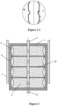
Figure 3 is a schematic top view of the horizontal flow sand filter basin according to the present application; and -
Figure 4 is another schematic top view of a horizontal flow sand filter basin according to the present application. - Reference Numerals in figures:
1 basin body, 2 water inlet pipe, 3 water distribution device, 4 sand filter bed, 5 water collector, 51 sieve plate, 52 cover plate, 6 water collecting branch pipe, 7 water outlet pipe, 8 backwash pipe, 9 drainage pipe, 10 aeration pipe, 11 aeration device. - The technical solutions according to the present application will be further described hereinafter through specific embodiments in conjunction with the drawings. It should be understood that the embodiments of the present application are not limited to the embodiments described hereinafter, and any form of modifications and/or changes made to the present application are deemed to fall into the scope of the present application.
- As shown in
Figure 1, Figure 2 ,Figure 2-1 and Figure 3 , a horizontal flow sand filter basin is composed of abasin body 1, a raw water inlet assembly, asand filter bed 4, a filtered water outlet assembly, an aeration assembly, and a backwash assembly. The raw water inlet assembly is configured to feed raw water into thesand filter bed 4 and distribute the raw water uniformly. - The
basin body 1 is rectangle shaped and made of concrete. - The raw water inlet assembly is composed of a
water inlet pipe 2 and awater distribution device 3 connected to thewater inlet pipe 2, thewater inlet pipe 2 is provided with a valve, and thewater inlet pipe 2 is configured for introducing the raw water into the horizontal flow sand filter basin. Thewater distribution device 3 is embodied as four water distribution stand pipes, water outlet orifices are uniformly distributed in each of the water distribution stand pipes, and the water distribution stand pipes are vertically arranged and uniformly distributed in thesand filter bed 4. The water distribution stand pipe may be formed by enclosure of a sieve plate having a wedge-wire filter surface, and the raw water enters thesand filter bed 4 uniformly and smoothly through sieve slits of the sieve plate. A water distribution structure of the water distribution stand pipes according to the present application is not limited thereto, and this is merely a preferred embodiment. - The
sand filter bed 4, composed of filter sand, is located in thebasin body 1 and extends upward from a bottom of thebasin body 1, and thesand filter bed 4 is configured to filter the raw water. The filter sand is the main material for purifying and filtering the raw water, quartz sand, activated carbon, anthracite, glass ball, ceramsite and other filter media may be chosen, and a type of the filter sand and particle gradation should be selected according to raw water quality and water quality requirements of filtered water. - The filtered water outlet assembly is composed of a
water collector 5, water collectingbranch pipes 6 and awater outlet pipe 7. Thewater collector 5 includes asieve plate 51 having a wedge-wire filter surface and twocover plates 52 respectively located at an upper end and a lower end of thesieve plate 51, a water collecting space is formed on an inner wall of thebasin body 1 by thesieve plate 51 and the twocover plates 52. Thewater collector 5 is provided with the water collectingbranch pipes 6 in communication with an outside of thebasin body 1, and an outlet of each of the water collectingbranch pipes 6 is connected to thewater outlet pipe 7 at an outer wall of thebasin body 1. The filtered water which has passed through thesand filter bed 4 enters thewater collector 5 through sieve slits of thesieve plate 51. As shown inFigure 3 ,sieve plates 51 in this embodiment are arc-shaped sheets, and protrusions of thesieve plates 51 are toward an inside of thebasin body 1. An inner wall of each of two sides of thebasin body 1 is provided with four arc-shaped sheets, the four arc-shaped sheets are arranged at uniform intervals along the inner wall of thebasin body 1, and thesieve plates 51 having shapes of arc sheets are configured for better collecting the filtered water which has passed through thesand filter bed 4. The water collectingbranch pipes 6 are connected to thewater collector 5. Thewater outlet pipe 7 drains the filtered water which has passed through thesand filter bed 4 out of thebasin body 1. - The backwash assembly includes a
backwash pipe 8 and adrainage pipe 9, thebackwash pipe 8 is provided with a valve and connected with thewater outlet pipe 7, and thedrainage pipe 9 is provided with a valve and connected to bottoms of the four water distribution stand pipes. Flushing water enters thewater collector 5 through thebackwash pipe 8, and thedrainage pipe 9 drains waste water of sand washing out of the horizontal flow sand filter basin. - The aeration assembly is composed of an
aeration pipe 10 andmultiple aeration devices 11 connected to theaeration pipe 10. During a backwash process of the sand filter basin, compressed air passes through the aeration assembly and is released into the sand filter basin in a form of small bubbles. The aeration assembly is mounted at the bottom of thebasin body 1. - A water treatment process of a horizontal flow sand filter basin includes the following two processes:
- 1. filtration process. The valve in the
water inlet pipe 2 is opened, the valve in thewater outlet pipe 7 is opened, the valve in thebackwash pipe 8 is closed, and the valve in thedrainage pipe 9 is closed. The raw water enters the horizontal flow sand filter basin through thewater inlet pipe 2, then enters thesand filter bed 4 uniformly and smoothly through the water distribution stand pipes, and then flows past the filter sand in a horizontal direction of thebasin body 1 from inside to outside. During the filtration process, large-sized suspended particles or contaminants in the water are intercepted by sand grains at an inner layer, and small-sized contaminants are deposited between sand grains at an outer layer, and efficiency of the filter sand is maximized with the inside to outside filtration. Finally, the filtered water is collected by thewater collector 5 uniformly arranged on the inner wall of thebasin body 1, the filtered water flows through the water collectingbranch pipes 6, and is converged in thewater outlet pipe 7 and drained out. - 2. backwash process. The valve in the
water inlet pipe 2 is closed, the valve in thewater outlet pipe 7 is closed, the valve in thebackwash pipe 8 is opened, and the valve in thedrainage pipe 9 is closed. The part of the filtered water which is temporarily stored is used as the flushing water, the flushing water enters thewater collector 5 on the inner wall of thebasin body 1 through the backwash pipe, and enters thesand filter bed 4 through orifices in a surface of thewater collector 5. The compressed air is fed into theaeration pipe 10, passes through theaeration devices 11 at the bottom of thebasin body 1, and enters thesand filter bed 4 from bottom to top in the form of bubbles. Impurities and contaminants are separated from surfaces of the sand grains by gas phase agitation, a shearing force of water flow and collision and friction between the sand grains, and enter the flushing water. During the horizontal flow filtration process, a degree of soiling of the sand grains is gradually decreased from around the water distribution stand pipes to walls of the sand filter basin. A degree of the gas phase agitation is adjusted, to control tumbling of the sand grains within a certain range, and by reverse cleaning of the flushing water, the dirty sand grains in different areas having different degrees of soiling are respectively cleaned without being mixed. After a period of time, the valve of thedrainage pipe 9 is opened, the valve of thebackwash pipe 8 is still opened, and the flushing water with contaminations is converged in the water distribution stand pipes, and drained out of the horizontal flow sand filter basin through thedrainage pipe 9. - The horizontal flow sand filter basin according to the present application can also realize a function of a biological filter. The biological filter employs aerobic microorganisms to perform biological oxidization to the raw water. Another water treatment process of a horizontal flow biological filter includes the following two processes:
- 1. biological filtration process. A gelatinous biofilm is formed on a surface of the filter sand under a suitable culture condition. The raw water enters the horizontal flow sand filter basin through the
water inlet pipe 2, and enters thesand filter bed 4 uniformly and smoothly through the water distribution stand pipes, and flows past the filter sand in the horizontal direction of thebasin body 1 from inside to outside. The aeration assembly is started, the compressed air passes through the aeration assembly, and is released into the sand filter basin from bottom to top in the form of small bubbles, so as to fully supply oxygen. When the raw water flows past the surface of the filter sand, the soluble, gelatinous and suspended substances in the raw water are adsorbed on the biofilm and degraded by the microorganisms. Finally, the filtered water is collected by thewater collector 5 on the inner wall of thebasin body 1, flows through the water collectingbranch pipes 6, and is converged in thewater outlet pipe 7 and drained out. - 2. backwash process. The backwash process is the same as the backwash process described above.
- A horizontal flow sand filter basin includes a
basin body 1, a raw water inlet assembly, asand filter bed 4, a filtered water outlet assembly, a backwash assembly and an aeration assembly, and the specific structure of the horizontal flow sand filter basin is similar to that in theembodiment 1, and the differences are as follows. - As shown in
Figure 4 , an inside of thebasin body 1 is divided into four circular regions corresponding to fourwater distribution devices 3, respectively. The circular regions are arranged in a rectangular shape, and each of the circular regions is provided with onesand filter bed 4 and onewater distribution device 3. Thewater inlet pipe 2 in the raw water inlet assembly is connected to the fourwater distribution devices 3 respectively; thewater distribution device 3 is a water distribution stand pipe, and the water distribution stand pipe may be formed by enclosure of a slot sieve. Bottoms of the four water distribution stand pipes are connected to thedrainage pipes 9. - The filtered water outlet assembly is composed of a
water collector 5 and awater outlet pipe 7.Sieve plates 51 in thewater collector 5 are cylindrical slot sieves, and thesieve plates 51 are fixed to inner walls of thebasin body 1.Cover plates 52 are determined according to projection configurations of thesieve plates 51 and the inner walls of thebasin body 1 on a horizontal surface. A water collecting space is defined by thesieve plates 51, an upper cover plate and a lower cover plate of each of thesieve plates 51, and the inner walls of thebasin body 1, and the water collecting space is shared by theentire basin body 1. The water collecting space can temporarily store the filtered water. Thewater outlet pipe 7 is in communication with the water collecting space. - The water treatment process of the horizontal flow sand filter basin according to this embodiment is similar to that of the first embodiment, and the differences are as follows.
- The filtered water enters the water collecting space formed by the
water collector 5 and the inner walls of thebasin body 1, and is drained through thewater outlet pipe 7. The above water collecting space may function to temporarily store the filtered water. - Only two preferred embodiments of the present application are described above, which are not intended to limit the present application in any form. There are other variants and modifications without departing from the scope of the appended claims.
Claims (10)
- A horizontal flow sand filter basin, comprising: a basin body (1), a raw water inlet assembly, a sand filter bed (4), a filtered water outlet assembly, an aeration assembly and a backwash assembly, whereinthe sand filter bed (4) is arranged in the basin body (1), and the sand filter bed (4) is composed of filter sand;the raw water inlet assembly comprises a water inlet pipe (2) and a water distribution device (3) for feeding raw water into the sand filter bed (4), the water inlet pipe (2) is connected to the water distribution device (3), the water distribution device (3) is arranged in the sand filter bed (4), and a plurality of water outlet orifices are distributed in a vertical face of the water distribution device (3);the filtered water outlet assembly comprises a water collector (5) and a water outlet pipe (7), a side of the water collector (5) adjacent to the sand filter bed (4) is provided with a water inlet orifice, and the water outlet pipe (7) is in communication with the water collector (5);the backwash assembly comprises a backwash pipe (8) and a drainage pipe (9), and the drainage pipe (9) is connected to the water distribution device (3);characterized in that,the backwash pipe (8) is connected to the water outlet pipe (7),the aeration assembly is mounted at the bottom of the basin body (1) and comprises an aeration pipe (10) and a plurality of aeration devices (11) connected to the aeration pipe (10).
- The horizontal flow sand filter basin according to claim 1, wherein the water distribution device (3) is arranged in an axial direction of the sand filter bed (4), or the water distribution device (3) is arranged along an outer wall of the sand filter bed (4).
- The horizontal flow sand filter basin according to claim 1 or 2, wherein the water collector (5) comprises a sieve plate (51) and two cover plates (52) respectively located at an upper end and a lower end of the sieve plate (51), and a water collecting space is defined in the basin body (1) by the sieve plate (51) and the two cover plates (52).
- The horizontal flow sand filter basin according to claim 2, wherein in a case that the water distribution device (3) is arranged along the outer wall of the sand filter bed (4), the water collector (5) is arranged in the axial direction of the sand filter bed (4).
- The horizontal flow sand filter basin according to claim 1, wherein the water distribution device (3) is formed by enclosure of a sieve plate (51) having a wedge-wire filter surface, or one of a perforated pipe and a slot sieve, or any combination of the sieve plate (51) having the wedge-wire filter surface, the perforated pipe and the slot sieve; the water collector (5) is formed by enclosure of the sieve plate (51) having the wedge-wire filter surface, or one of the perforated pipe, the slot sieve, a microfiltration membrane and an ultrafiltration membrane, or any combination of the sieve plate (51) having the wedge-wire filter surface, the perforated pipe, the slot sieve, the microfiltration membrane and the ultrafiltration membrane.
- The horizontal flow sand filter basin according to claim 1, wherein a layout of the water distribution device (3) is embodied as a rectangular shape, a circular shape, an annular shape or a linear shape, or any combination of the rectangular shape, the circular shape, the annular shape and the linear shape.
- The horizontal flow sand filter basin according to claim 5, wherein the sieve plate (51) in the water collector (5) is embodied as sheet-like structures arranged continuously or at intervals along an inner wall of the basin body (1), the sheet-like structures are arc-shaped sheets, terrace-shaped sheets, bent sheets, flat sheets or sheets of other geometric shapes, and protrusions of the sieve plate (51) are towards an inside of the basin body (1); or
the sieve plate (51) is a cylinder on which water distribution holes are distributed. - The horizontal flow sand filter basin according to claim 1, wherein the water collector (5) is provided with at least one water collecting branch pipe (6) in communication with an outside of the basin body (1), and an outlet of the water collecting branch pipe (6) is connected to the water outlet pipe (7) outside the basin body (1).
- A water treatment process of the horizontal flow sand filter basin according to claim 1, wherein the water treatment process comprises the following two processes:1). filtration process: feeding raw water into the horizontal flow sand filter basin through the water inlet pipe (2), allowing the raw water to enter the sand filter bed (4) uniformly and smoothly through water outlet orifices of the water distribution device (3), and flow past filter sand in a horizontal direction of the basin body (1) from inside to outside or from outside to inside; during the filtration process, gradually intercepting, by sand grains, suspended particles or contaminants in the water, and an efficiency of the filter sand is maximized by radial filtration; finally, collecting filtered water by the water collector (5), converging the filtered water in the water outlet pipe (7), and discharging the filtered water;2). backwash process: allowing flushing water to enter the basin body (1) through the backwash pipe (8) and enter the sand filter bed (4); feeding compressed air into the aeration pipe (10), and allowing the compressed air to enter the sand filter bed (4) from bottom to top in a form of bubbles through the aeration device (11) at a bottom of the basin body (1), allowing the impurities and the contaminants to be separated from surfaces of the sand grains by gas phase agitation, a shearing force of water flow and collision and friction between the sand grains, and allowing the impurities and the contaminants to enter the flushing water; controlling tumbling of the sand grains by adjusting a degree of the gas phase agitation, and by reverse cleaning of the flushing water, the dirty sand grains in different areas having different degrees of soiling are respectively cleaned without being mixed; after a period of time, converging the flushing water having the contaminations in the water distribution device (3), and discharging the flushing water out of the horizontal flow sand filter basin through the drainage pipe (9).
- The water treatment process according to claim 9, wherein the filtration process is a biological filtration process, whereinbefore the feeding raw water into the horizontal flow sand filter basin through the water inlet pipe (2), the filtration process further comprises:
forming a gelatinous aerobic microorganisms biofilm on a surface of filter sand; andafter the feeding raw water into the horizontal flow sand filter basin through the water inlet pipe (2), the filtration process further comprises:starting an aeration assembly, and allowing compressed air to pass through the aeration assembly to be released into the sand filter basin from bottom to top in an form of small bubbles, so as to fully supply oxygen; andwhen the raw water flows past a surface of the filter sand, allowing soluble, gelatinous and suspended substances in the raw water to be adsorbed on the biofilm and degraded by aerobic microorganisms.
Applications Claiming Priority (3)
| Application Number | Priority Date | Filing Date | Title |
|---|---|---|---|
| CN201621328393.XU CN206553348U (en) | 2016-12-06 | 2016-12-06 | A kind of level stream sand filter |
| CN201611109076.3A CN106731060A (en) | 2016-12-06 | 2016-12-06 | Level stream sand filter and its water treatment technology |
| PCT/CN2017/112605 WO2018103537A1 (en) | 2016-12-06 | 2017-11-23 | Horizontal-flow sand filtration pool and water treatment process thereof |
Publications (3)
| Publication Number | Publication Date |
|---|---|
| EP3552679A1 EP3552679A1 (en) | 2019-10-16 |
| EP3552679A4 EP3552679A4 (en) | 2019-12-25 |
| EP3552679B1 true EP3552679B1 (en) | 2023-06-07 |
Family
ID=62491482
Family Applications (1)
| Application Number | Title | Priority Date | Filing Date |
|---|---|---|---|
| EP17878216.5A Active EP3552679B1 (en) | 2016-12-06 | 2017-11-23 | Horizontal-flow sand filtration basin and water treatment process thereof |
Country Status (9)
| Country | Link |
|---|---|
| US (1) | US11180395B2 (en) |
| EP (1) | EP3552679B1 (en) |
| JP (1) | JP6797303B2 (en) |
| AU (1) | AU2017372226B2 (en) |
| DK (1) | DK3552679T3 (en) |
| ES (1) | ES2955163T3 (en) |
| FI (1) | FI3552679T3 (en) |
| PL (1) | PL3552679T3 (en) |
| WO (1) | WO2018103537A1 (en) |
Cited By (1)
| Publication number | Priority date | Publication date | Assignee | Title |
|---|---|---|---|---|
| DE202023106057U1 (en) | 2023-10-19 | 2023-12-01 | Passavant-Geiger Gmbh | Parallel flow filter basin for cleaning wastewater |
Families Citing this family (9)
| Publication number | Priority date | Publication date | Assignee | Title |
|---|---|---|---|---|
| DE102017131089B4 (en) * | 2017-12-22 | 2022-06-30 | Jassen - Kunststoffzentrum Gmbh - Apparatebau, Zuschnitte Und Formung | Bioreactor and its use, method for producing an organic nutrient solution and organic nutrient solution |
| CN110117061A (en) * | 2019-05-20 | 2019-08-13 | 湖南三友环保科技股份有限公司 | A kind of washed-out sand rhone and biological aerated filter |
| CN112174302A (en) * | 2020-10-22 | 2021-01-05 | 四川欧美华环境工程有限公司 | Novel biological aerated filter adopting filter bricks in upward flow |
| CN114563314A (en) * | 2022-02-11 | 2022-05-31 | 北京建筑材料科学研究总院有限公司 | Rapid automatic detection system and method for concrete sand entering field |
| CN114377442B (en) * | 2022-03-01 | 2023-03-21 | 中冶赛迪信息技术(重庆)有限公司 | On-line backwashing state detection method for sand filter |
| CN114772852B (en) * | 2022-04-25 | 2023-06-16 | 北京华宇辉煌生态环保科技股份有限公司 | Sewage treatment device |
| CN114890570B (en) * | 2022-06-24 | 2024-04-16 | 上海市政工程设计研究总院(集团)有限公司 | Reverse series connection carbon sand filter tank and water filtering method |
| CN115350523A (en) * | 2022-08-26 | 2022-11-18 | 金剑环保集团有限公司 | Vertical pipe installation mode of bread pipe water and gas distribution system |
| CN115520972A (en) * | 2022-10-27 | 2022-12-27 | 上海城投水务(集团)有限公司制水分公司 | Device and method for regulating and controlling leakage of micro-animals in biological activated carbon filter |
Family Cites Families (22)
| Publication number | Priority date | Publication date | Assignee | Title |
|---|---|---|---|---|
| DE2208513A1 (en) | 1972-02-18 | 1973-08-30 | Intercooperation Kereskedelemf | Filtering plant - with external regeneration of filtering medium facilitating continuous operation |
| JPS5135161A (en) | 1974-09-20 | 1976-03-25 | Kirisawa Kankyo Gijutsu Kenkyu | |
| JPS5223176B2 (en) | 1974-10-22 | 1977-06-22 | ||
| DE2608899C3 (en) * | 1976-03-04 | 1982-12-30 | Müller, Wolf-Rüdiger, Dipl.-Ing., 7000 Stuttgart | Process to improve the backwashing process for filters made of granular materials through the use of hydrogen peroxide (H ↓ 2 ↓ O ↓ 2 ↓) |
| JPS5314465A (en) | 1976-07-24 | 1978-02-09 | Kazuyoshi Tsuji | Liquid filter system |
| SU747491A1 (en) | 1978-02-03 | 1980-07-15 | Ордена Трудового Красного Знамени Институт Физической Химии Ан Ссср | Water cleaning filter |
| US4894149A (en) * | 1988-09-16 | 1990-01-16 | Block Steven J | Biological filtration device |
| US5122287A (en) * | 1990-10-26 | 1992-06-16 | Hsiung Andrew K | Filtration system |
| JPH10151473A (en) | 1996-11-26 | 1998-06-09 | Tokico Ltd | Water purifying apparatus |
| US6767457B2 (en) * | 2001-01-19 | 2004-07-27 | Ez Set Tank Company | Recirculating filter |
| US6521126B2 (en) * | 2001-05-01 | 2003-02-18 | David K. Wyness | Pipe gallery for water filtration systems |
| EP1838629A4 (en) * | 2004-11-22 | 2010-11-24 | Water Systems Pty Limited Nubian | Waste water treatment process system |
| US7914678B2 (en) * | 2008-05-30 | 2011-03-29 | Beggs Robert A | Backwashing unsaturated wastewater filter |
| CN101450268A (en) * | 2008-12-08 | 2009-06-10 | 苏州嘉净水处理设备有限公司 | Filter-tank uniform water distribution device |
| NO329665B1 (en) * | 2009-06-03 | 2010-11-29 | Biowater Technology AS | Process and reactor for treatment of water |
| CN201692706U (en) * | 2010-06-11 | 2011-01-05 | 山东建筑大学 | Absorption filtering pool |
| CN203999002U (en) * | 2014-06-24 | 2014-12-10 | 青岛南车华轩水务有限公司 | A kind of radial-flow multimedium waste disposal plant |
| CN204447440U (en) * | 2014-12-26 | 2015-07-08 | 杭州国泰环保科技股份有限公司 | Sand filter filtration treatment system |
| CN105727603A (en) * | 2016-03-08 | 2016-07-06 | 北京沃奇新德山水实业有限公司 | Bi-directional synchronous filtering equipment, water treatment system employing same and backwashing method of same |
| CN205710288U (en) * | 2016-04-05 | 2016-11-23 | 湖南艾布鲁环保科技有限公司 | A kind of water correction being applied to black and odorous water improvement and restoration of the ecosystem facility |
| CN206553348U (en) * | 2016-12-06 | 2017-10-13 | 欧盛腾水处理技术(杭州)有限公司 | A kind of level stream sand filter |
| CN106731060A (en) * | 2016-12-06 | 2017-05-31 | 欧盛腾水处理技术(杭州)有限公司 | Level stream sand filter and its water treatment technology |
-
2017
- 2017-11-23 FI FIEP17878216.5T patent/FI3552679T3/en active
- 2017-11-23 US US16/467,488 patent/US11180395B2/en active Active
- 2017-11-23 PL PL17878216.5T patent/PL3552679T3/en unknown
- 2017-11-23 WO PCT/CN2017/112605 patent/WO2018103537A1/en unknown
- 2017-11-23 DK DK17878216.5T patent/DK3552679T3/en active
- 2017-11-23 AU AU2017372226A patent/AU2017372226B2/en active Active
- 2017-11-23 ES ES17878216T patent/ES2955163T3/en active Active
- 2017-11-23 EP EP17878216.5A patent/EP3552679B1/en active Active
- 2017-11-23 JP JP2019531247A patent/JP6797303B2/en active Active
Cited By (1)
| Publication number | Priority date | Publication date | Assignee | Title |
|---|---|---|---|---|
| DE202023106057U1 (en) | 2023-10-19 | 2023-12-01 | Passavant-Geiger Gmbh | Parallel flow filter basin for cleaning wastewater |
Also Published As
| Publication number | Publication date |
|---|---|
| US11180395B2 (en) | 2021-11-23 |
| AU2017372226A1 (en) | 2019-07-04 |
| EP3552679A4 (en) | 2019-12-25 |
| JP2020500704A (en) | 2020-01-16 |
| ES2955163T3 (en) | 2023-11-29 |
| WO2018103537A1 (en) | 2018-06-14 |
| FI3552679T3 (en) | 2023-09-05 |
| PL3552679T3 (en) | 2024-01-22 |
| JP6797303B2 (en) | 2020-12-09 |
| DK3552679T3 (en) | 2023-09-18 |
| AU2017372226B2 (en) | 2020-05-07 |
| US20190330090A1 (en) | 2019-10-31 |
| EP3552679A1 (en) | 2019-10-16 |
Similar Documents
| Publication | Publication Date | Title |
|---|---|---|
| EP3552679B1 (en) | Horizontal-flow sand filtration basin and water treatment process thereof | |
| CN109179872A (en) | A kind of water treatment facilities and water treatment technology based on basalt fibre | |
| CN107570014A (en) | A kind of quick detachable high flux Dynamic Membrane supporting construction and component | |
| CN210117322U (en) | High-efficiency biological aerated filter for treating industrial wastewater difficult to degrade | |
| MX2008004820A (en) | Saf system and method involving specific treatments at respective stages. | |
| CN106731060A (en) | Level stream sand filter and its water treatment technology | |
| CN218924072U (en) | Quick precipitation membrane system | |
| CN110589964A (en) | Internal circulation high-efficiency denitrification biological denitrification filter tank | |
| CN206553348U (en) | A kind of level stream sand filter | |
| USRE28458E (en) | Apparatus and method of filtering solids from a liquid effluent | |
| CN206466978U (en) | A kind of floor filter of three Room four with backwashing function | |
| CN204434354U (en) | A kind of bioreactor of dynamic membrane for industrial sewage of degrading | |
| CA2565052A1 (en) | System for improved dissolved air floatation with a biofilter | |
| CN211521968U (en) | Ozone contact and active carbon filter integrated form water purification system | |
| JP2017185477A (en) | Apparatus and method for increasing uniform effluent flow through wastewater treatment system | |
| CN102180564B (en) | Highly-efficient aeration biological filter applied to advanced printing and dyeing wastewater treatment and treatment method thereof | |
| CN204952442U (en) | A filter plate for filter | |
| CN217247007U (en) | Alternate circulating type filtering tank | |
| CN219752053U (en) | Wastewater treatment device | |
| CN213589861U (en) | Full-automatic differential pressure filter | |
| KR20010088734A (en) | A settling filter tank and, an apparatus and a method for treating waste water using the same settling filter tank | |
| CN217745881U (en) | Little biochemical filter equipment | |
| CN217119445U (en) | Sewage purification device | |
| CN213416588U (en) | Denitrification filter tank with anthracite and quartz sand double-layer filter material | |
| CN208022775U (en) | Biological membrane-membrane biological coupling sewage-treatment plant |
Legal Events
| Date | Code | Title | Description |
|---|---|---|---|
| STAA | Information on the status of an ep patent application or granted ep patent |
Free format text: STATUS: THE INTERNATIONAL PUBLICATION HAS BEEN MADE |
|
| PUAI | Public reference made under article 153(3) epc to a published international application that has entered the european phase |
Free format text: ORIGINAL CODE: 0009012 |
|
| STAA | Information on the status of an ep patent application or granted ep patent |
Free format text: STATUS: REQUEST FOR EXAMINATION WAS MADE |
|
| 17P | Request for examination filed |
Effective date: 20190701 |
|
| AK | Designated contracting states |
Kind code of ref document: A1 Designated state(s): AL AT BE BG CH CY CZ DE DK EE ES FI FR GB GR HR HU IE IS IT LI LT LU LV MC MK MT NL NO PL PT RO RS SE SI SK SM TR |
|
| AX | Request for extension of the european patent |
Extension state: BA ME |
|
| A4 | Supplementary search report drawn up and despatched |
Effective date: 20191126 |
|
| RIC1 | Information provided on ipc code assigned before grant |
Ipc: B01D 24/46 20060101ALI20191120BHEP Ipc: C02F 3/34 20060101ALI20191120BHEP Ipc: C02F 3/02 20060101ALI20191120BHEP Ipc: B01D 24/10 20060101AFI20191120BHEP |
|
| DAV | Request for validation of the european patent (deleted) | ||
| DAX | Request for extension of the european patent (deleted) | ||
| STAA | Information on the status of an ep patent application or granted ep patent |
Free format text: STATUS: EXAMINATION IS IN PROGRESS |
|
| 17Q | First examination report despatched |
Effective date: 20210312 |
|
| STAA | Information on the status of an ep patent application or granted ep patent |
Free format text: STATUS: EXAMINATION IS IN PROGRESS |
|
| RAP1 | Party data changed (applicant data changed or rights of an application transferred) |
Owner name: PASSAVANT-GEIGER GMBH |
|
| GRAP | Despatch of communication of intention to grant a patent |
Free format text: ORIGINAL CODE: EPIDOSNIGR1 |
|
| STAA | Information on the status of an ep patent application or granted ep patent |
Free format text: STATUS: GRANT OF PATENT IS INTENDED |
|
| INTG | Intention to grant announced |
Effective date: 20221130 |
|
| GRAS | Grant fee paid |
Free format text: ORIGINAL CODE: EPIDOSNIGR3 |
|
| GRAA | (expected) grant |
Free format text: ORIGINAL CODE: 0009210 |
|
| STAA | Information on the status of an ep patent application or granted ep patent |
Free format text: STATUS: THE PATENT HAS BEEN GRANTED |
|
| AK | Designated contracting states |
Kind code of ref document: B1 Designated state(s): AL AT BE BG CH CY CZ DE DK EE ES FI FR GB GR HR HU IE IS IT LI LT LU LV MC MK MT NL NO PL PT RO RS SE SI SK SM TR |
|
| REG | Reference to a national code |
Ref country code: GB Ref legal event code: FG4D |
|
| REG | Reference to a national code |
Ref country code: CH Ref legal event code: EP Ref country code: AT Ref legal event code: REF Ref document number: 1573239 Country of ref document: AT Kind code of ref document: T Effective date: 20230615 |
|
| REG | Reference to a national code |
Ref country code: DE Ref legal event code: R096 Ref document number: 602017069994 Country of ref document: DE |
|
| P01 | Opt-out of the competence of the unified patent court (upc) registered |
Effective date: 20230525 |
|
| REG | Reference to a national code |
Ref country code: DK Ref legal event code: T3 Effective date: 20230911 |
|
| REG | Reference to a national code |
Ref country code: NL Ref legal event code: FP |
|
| REG | Reference to a national code |
Ref country code: LT Ref legal event code: MG9D |
|
| REG | Reference to a national code |
Ref country code: SE Ref legal event code: TRGR |
|
| REG | Reference to a national code |
Ref country code: NO Ref legal event code: T2 Effective date: 20230607 |
|
| REG | Reference to a national code |
Ref country code: ES Ref legal event code: FG2A Ref document number: 2955163 Country of ref document: ES Kind code of ref document: T3 Effective date: 20231129 |
|
| PG25 | Lapsed in a contracting state [announced via postgrant information from national office to epo] |
Ref country code: RS Free format text: LAPSE BECAUSE OF FAILURE TO SUBMIT A TRANSLATION OF THE DESCRIPTION OR TO PAY THE FEE WITHIN THE PRESCRIBED TIME-LIMIT Effective date: 20230607 Ref country code: LV Free format text: LAPSE BECAUSE OF FAILURE TO SUBMIT A TRANSLATION OF THE DESCRIPTION OR TO PAY THE FEE WITHIN THE PRESCRIBED TIME-LIMIT Effective date: 20230607 Ref country code: LT Free format text: LAPSE BECAUSE OF FAILURE TO SUBMIT A TRANSLATION OF THE DESCRIPTION OR TO PAY THE FEE WITHIN THE PRESCRIBED TIME-LIMIT Effective date: 20230607 Ref country code: HR Free format text: LAPSE BECAUSE OF FAILURE TO SUBMIT A TRANSLATION OF THE DESCRIPTION OR TO PAY THE FEE WITHIN THE PRESCRIBED TIME-LIMIT Effective date: 20230607 Ref country code: GR Free format text: LAPSE BECAUSE OF FAILURE TO SUBMIT A TRANSLATION OF THE DESCRIPTION OR TO PAY THE FEE WITHIN THE PRESCRIBED TIME-LIMIT Effective date: 20230908 |
|
| PGFP | Annual fee paid to national office [announced via postgrant information from national office to epo] |
Ref country code: NL Payment date: 20231122 Year of fee payment: 7 |
|
| PG25 | Lapsed in a contracting state [announced via postgrant information from national office to epo] |
Ref country code: SK Free format text: LAPSE BECAUSE OF FAILURE TO SUBMIT A TRANSLATION OF THE DESCRIPTION OR TO PAY THE FEE WITHIN THE PRESCRIBED TIME-LIMIT Effective date: 20230607 |
|
| PGFP | Annual fee paid to national office [announced via postgrant information from national office to epo] |
Ref country code: GB Payment date: 20231123 Year of fee payment: 7 |
|
| PGFP | Annual fee paid to national office [announced via postgrant information from national office to epo] |
Ref country code: ES Payment date: 20231215 Year of fee payment: 7 |
|
| PG25 | Lapsed in a contracting state [announced via postgrant information from national office to epo] |
Ref country code: IS Free format text: LAPSE BECAUSE OF FAILURE TO SUBMIT A TRANSLATION OF THE DESCRIPTION OR TO PAY THE FEE WITHIN THE PRESCRIBED TIME-LIMIT Effective date: 20231007 |
|
| PG25 | Lapsed in a contracting state [announced via postgrant information from national office to epo] |
Ref country code: SM Free format text: LAPSE BECAUSE OF FAILURE TO SUBMIT A TRANSLATION OF THE DESCRIPTION OR TO PAY THE FEE WITHIN THE PRESCRIBED TIME-LIMIT Effective date: 20230607 Ref country code: SK Free format text: LAPSE BECAUSE OF FAILURE TO SUBMIT A TRANSLATION OF THE DESCRIPTION OR TO PAY THE FEE WITHIN THE PRESCRIBED TIME-LIMIT Effective date: 20230607 Ref country code: RO Free format text: LAPSE BECAUSE OF FAILURE TO SUBMIT A TRANSLATION OF THE DESCRIPTION OR TO PAY THE FEE WITHIN THE PRESCRIBED TIME-LIMIT Effective date: 20230607 Ref country code: PT Free format text: LAPSE BECAUSE OF FAILURE TO SUBMIT A TRANSLATION OF THE DESCRIPTION OR TO PAY THE FEE WITHIN THE PRESCRIBED TIME-LIMIT Effective date: 20231009 Ref country code: IS Free format text: LAPSE BECAUSE OF FAILURE TO SUBMIT A TRANSLATION OF THE DESCRIPTION OR TO PAY THE FEE WITHIN THE PRESCRIBED TIME-LIMIT Effective date: 20231007 Ref country code: EE Free format text: LAPSE BECAUSE OF FAILURE TO SUBMIT A TRANSLATION OF THE DESCRIPTION OR TO PAY THE FEE WITHIN THE PRESCRIBED TIME-LIMIT Effective date: 20230607 |
|
| PGFP | Annual fee paid to national office [announced via postgrant information from national office to epo] |
Ref country code: TR Payment date: 20231115 Year of fee payment: 7 Ref country code: SE Payment date: 20231123 Year of fee payment: 7 Ref country code: NO Payment date: 20231121 Year of fee payment: 7 Ref country code: IT Payment date: 20231130 Year of fee payment: 7 Ref country code: FR Payment date: 20231122 Year of fee payment: 7 Ref country code: FI Payment date: 20231120 Year of fee payment: 7 Ref country code: DK Payment date: 20231122 Year of fee payment: 7 Ref country code: DE Payment date: 20231124 Year of fee payment: 7 Ref country code: CZ Payment date: 20231110 Year of fee payment: 7 Ref country code: CH Payment date: 20231201 Year of fee payment: 7 Ref country code: AT Payment date: 20231117 Year of fee payment: 7 |
|
| REG | Reference to a national code |
Ref country code: AT Ref legal event code: UEP Ref document number: 1573239 Country of ref document: AT Kind code of ref document: T Effective date: 20230607 |
|
| PGFP | Annual fee paid to national office [announced via postgrant information from national office to epo] |
Ref country code: BE Payment date: 20231121 Year of fee payment: 7 |