EP3552679B1 - Horizontalfluss-sandfilterbecken und wasserbehandlungsverfahren damit - Google Patents
Horizontalfluss-sandfilterbecken und wasserbehandlungsverfahren damit Download PDFInfo
- Publication number
- EP3552679B1 EP3552679B1 EP17878216.5A EP17878216A EP3552679B1 EP 3552679 B1 EP3552679 B1 EP 3552679B1 EP 17878216 A EP17878216 A EP 17878216A EP 3552679 B1 EP3552679 B1 EP 3552679B1
- Authority
- EP
- European Patent Office
- Prior art keywords
- water
- sand filter
- pipe
- sand
- basin
- Prior art date
- Legal status (The legal status is an assumption and is not a legal conclusion. Google has not performed a legal analysis and makes no representation as to the accuracy of the status listed.)
- Active
Links
Images


Classifications
-
- B—PERFORMING OPERATIONS; TRANSPORTING
- B01—PHYSICAL OR CHEMICAL PROCESSES OR APPARATUS IN GENERAL
- B01D—SEPARATION
- B01D24/00—Filters comprising loose filtering material, i.e. filtering material without any binder between the individual particles or fibres thereof
- B01D24/02—Filters comprising loose filtering material, i.e. filtering material without any binder between the individual particles or fibres thereof with the filter bed stationary during the filtration
- B01D24/10—Filters comprising loose filtering material, i.e. filtering material without any binder between the individual particles or fibres thereof with the filter bed stationary during the filtration the filtering material being held in a closed container
-
- C—CHEMISTRY; METALLURGY
- C02—TREATMENT OF WATER, WASTE WATER, SEWAGE, OR SLUDGE
- C02F—TREATMENT OF WATER, WASTE WATER, SEWAGE, OR SLUDGE
- C02F3/00—Biological treatment of water, waste water, or sewage
- C02F3/34—Biological treatment of water, waste water, or sewage characterised by the microorganisms used
-
- B—PERFORMING OPERATIONS; TRANSPORTING
- B01—PHYSICAL OR CHEMICAL PROCESSES OR APPARATUS IN GENERAL
- B01D—SEPARATION
- B01D24/00—Filters comprising loose filtering material, i.e. filtering material without any binder between the individual particles or fibres thereof
- B01D24/002—Filters comprising loose filtering material, i.e. filtering material without any binder between the individual particles or fibres thereof with multiple filtering elements in parallel connection
-
- B—PERFORMING OPERATIONS; TRANSPORTING
- B01—PHYSICAL OR CHEMICAL PROCESSES OR APPARATUS IN GENERAL
- B01D—SEPARATION
- B01D24/00—Filters comprising loose filtering material, i.e. filtering material without any binder between the individual particles or fibres thereof
- B01D24/38—Feed or discharge devices
- B01D24/40—Feed or discharge devices for feeding
-
- B—PERFORMING OPERATIONS; TRANSPORTING
- B01—PHYSICAL OR CHEMICAL PROCESSES OR APPARATUS IN GENERAL
- B01D—SEPARATION
- B01D24/00—Filters comprising loose filtering material, i.e. filtering material without any binder between the individual particles or fibres thereof
- B01D24/46—Regenerating the filtering material in the filter
- B01D24/4631—Counter-current flushing, e.g. by air
-
- C—CHEMISTRY; METALLURGY
- C02—TREATMENT OF WATER, WASTE WATER, SEWAGE, OR SLUDGE
- C02F—TREATMENT OF WATER, WASTE WATER, SEWAGE, OR SLUDGE
- C02F3/00—Biological treatment of water, waste water, or sewage
- C02F3/02—Aerobic processes
-
- C—CHEMISTRY; METALLURGY
- C02—TREATMENT OF WATER, WASTE WATER, SEWAGE, OR SLUDGE
- C02F—TREATMENT OF WATER, WASTE WATER, SEWAGE, OR SLUDGE
- C02F3/00—Biological treatment of water, waste water, or sewage
- C02F3/02—Aerobic processes
- C02F3/04—Aerobic processes using trickle filters
- C02F3/046—Soil filtration
-
- C—CHEMISTRY; METALLURGY
- C02—TREATMENT OF WATER, WASTE WATER, SEWAGE, OR SLUDGE
- C02F—TREATMENT OF WATER, WASTE WATER, SEWAGE, OR SLUDGE
- C02F1/00—Treatment of water, waste water, or sewage
- C02F1/44—Treatment of water, waste water, or sewage by dialysis, osmosis or reverse osmosis
- C02F1/444—Treatment of water, waste water, or sewage by dialysis, osmosis or reverse osmosis by ultrafiltration or microfiltration
-
- Y—GENERAL TAGGING OF NEW TECHNOLOGICAL DEVELOPMENTS; GENERAL TAGGING OF CROSS-SECTIONAL TECHNOLOGIES SPANNING OVER SEVERAL SECTIONS OF THE IPC; TECHNICAL SUBJECTS COVERED BY FORMER USPC CROSS-REFERENCE ART COLLECTIONS [XRACs] AND DIGESTS
- Y02—TECHNOLOGIES OR APPLICATIONS FOR MITIGATION OR ADAPTATION AGAINST CLIMATE CHANGE
- Y02W—CLIMATE CHANGE MITIGATION TECHNOLOGIES RELATED TO WASTEWATER TREATMENT OR WASTE MANAGEMENT
- Y02W10/00—Technologies for wastewater treatment
- Y02W10/10—Biological treatment of water, waste water, or sewage
Definitions
- the present application relates to water treatment equipment, and in particular to a horizontal flow sand filter basin and a water treatment process thereof.
- a sand filter basin is typical filtration equipment having a filter layer, which uses surface areas provided by a granular material of the filter layer to intercept solid particles and colloids in water, so as to clarify the water.
- the sand filter basin can intercept impurities in water having a particle size much smaller than a gap in the filter material mainly through contact flocculation, and also through sieve filtration and precipitation. Because the sand filter basin has many advantages such as large decontamination capacity, long working period and reliable operation, it is widely used in feed water treatment or advanced treatment of sewage after secondary treatment.
- the operation of the sand filter basin is mainly a cycle of the two processes of filtration and backwash.
- the process of the raw water filtration is only carried out in a vertical direction, the filtration area is limited by the horizontal cross-sectional area of the equipment, and the sand layer is not fully utilized; during the flushing process of the sand grains, all the sand grains are mixed, and the sand grains cannot be classified and treated according to the degree of soiling of the sand grains.
- US4894149A discloses a filtration device, which includes an assembly of three concentric tubular members in longitudinal upright position, having a closure wall at each end, the inner and middle tubular members being perforated over substantially their entire length to permit water flow therethrough, and the outer tubular member being substantially solid over its entire length.
- An inlet is connected to the inner tubular member at each end, and an outlet is connected to the outer tubular member.
- the space between the inner tubular member and the middle tubular member is a filtration chamber containing a filtration medium.
- a dividing device is laterally positioned in the inner tubular member dividing it into upper and lower non-communicating portions, and a dividing device is also laterally positioned in the filtration chamber dividing it into upper and lower non-communicating filtration chambers.
- the filtration medium is adapted to not pass through the perforations of the inner and middle tubular members. Additional dividing devices may be located in the upper and lower filtration chambers, in order to divide them into chambers of a size approximately 1 cubic foot.
- One object of the present application is to provide a horizontal flow sand filter basin, to solve the problems in the conventional sand filtration technology that the filtration area of the sand layer is limited, the sand layer is not fully utilized, and the filter sand having different degrees of soiling is mixed and flushed together.
- a horizontal flow sand filter includes a basin body, a raw water inlet assembly, a sand filter bed, a filtered water outlet assembly, an aeration assembly and a backwash assembly.
- the sand filter bed is arranged in the basin body and is composed of filter sand;
- the water distribution device is arranged in an axial direction of the basin body or at an outer wall of the sand filter bed.
- the basin body is made of concrete. According to different process requirements, the basin body may also be made of other materials, such as steel, acrylic, or the like.
- the water distribution device is a water distribution stand pipe having a water outlet orifice.
- the water distribution device is formed by enclosure of a sieve plate having a wedge-wire filter surface, or one of a perforated pipe and a slot sieve, or any combination of the sieve plate having the wedge-wire filter surface, the perforated pipe and the slot sieve;
- the water collector is formed by enclosure of the sieve plate having the wedge-wire filter surface, or one of the perforated pipe, the slot sieve, a microfiltration membrane and an ultrafiltration membrane, or any combination of the sieve plate having the wedge-wire filter surface, the perforated pipe, the slot sieve, the microfiltration membrane and the ultrafiltration membrane.
- a layout of the water distribution device may employ multiple configurations such as a rectangular shape, a circular shape, an annular shape or a linear shape, or any combination of the rectangular shape, the circular shape, the annular shape and the linear shape.
- the water collector includes a sieve plate and two cover plates respectively located at a lower end and an upper end of the sieve plate, and a water collecting space is defined in the basin body by the sieve plate and the two cover plates.
- the water collector is arranged in the axial direction of the sand filter bed.
- the sieve plate in the water collector is embodied as sheet-like structures arranged continuously or at intervals along an inner wall of the basin body, the sheet-like structures may be arc-shaped sheets, terrace-shaped sheets, bent sheets, flat sheets or sheets of other geometric shapes, and protrusions of the sieve plate are towards an inside of the basin body; or the sieve plate is a cylinder on which water distribution holes are distributed.
- the sieve plate may also be of other forms, such as a continuous whole sheet, rectangular sheets arranged at intervals, or the like.
- the water collector is provided with at least one water collecting branch pipe in communication with an outside of the basin body, and an outlet of the water collecting branch pipe is connected to the water outlet pipe outside the basin body.
- the aeration assembly is composed of an aeration pipe and multiple aeration devices connected to the aeration pipe, and the aeration assembly is mounted at a bottom of the basin body.
- valves are arranged on the water inlet pipe, the water outlet pipe, the backwash pipe, and the drainage pipe.
- the backwash assembly is further provided with a backwash water tank configured for storing part of the filtered water, and the filtered water is used as flushing water in a flushing process, which greatly reduces the consumption of clean water.
- an aeration device is a sieve plate having a wedge-wire filter surface.
- the aeration device may also be of other forms, such as a perforated pipe, a slot sieve, or a rigid air distribution device with appropriate form or strength, or any combination of the sieve plate, the perforated pipe, the slot sieve and the rigid air distribution devices.
- a water treatment process of a horizontal flow sand filter basin includes the following two processes:
- a preferred example of the water treatment process of a horizontal flow sand filter basin includes a filtration process which is a biological filtration process, wherein before the feeding raw water into the horizontal flow sand filter basin through the water inlet pipe (2), the filtration process further comprises: forming a gelatinous aerobic microorganisms biofilm on a surface of filter sand; and after the feeding raw water into the horizontal flow sand filter basin through the water inlet pipe (2), the filtration process further comprises: starting an aeration assembly, and allowing compressed air to pass through the aeration assembly to be released into the sand filter basin from bottom to top in an form of small bubbles, so as to fully supply oxygen; and when the raw water flows past a surface of the filter sand, allowing soluble, gelatinous and suspended substances in the raw water to be adsorbed on the biofilm and degraded by aerobic microorganisms.
- part of the filtered water may be temporarily stored in the backwash water tank and reused as flushing water in the subsequent backwash process.
- the horizontal flow sand filter basin according to the present application can realize the following functions:
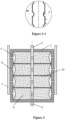
- a horizontal flow sand filter basin is composed of a basin body 1, a raw water inlet assembly, a sand filter bed 4, a filtered water outlet assembly, an aeration assembly, and a backwash assembly.
- the raw water inlet assembly is configured to feed raw water into the sand filter bed 4 and distribute the raw water uniformly.
- the basin body 1 is rectangle shaped and made of concrete.
- the raw water inlet assembly is composed of a water inlet pipe 2 and a water distribution device 3 connected to the water inlet pipe 2, the water inlet pipe 2 is provided with a valve, and the water inlet pipe 2 is configured for introducing the raw water into the horizontal flow sand filter basin.
- the water distribution device 3 is embodied as four water distribution stand pipes, water outlet orifices are uniformly distributed in each of the water distribution stand pipes, and the water distribution stand pipes are vertically arranged and uniformly distributed in the sand filter bed 4.
- the water distribution stand pipe may be formed by enclosure of a sieve plate having a wedge-wire filter surface, and the raw water enters the sand filter bed 4 uniformly and smoothly through sieve slits of the sieve plate.
- a water distribution structure of the water distribution stand pipes according to the present application is not limited thereto, and this is merely a preferred embodiment.
- the sand filter bed 4 composed of filter sand, is located in the basin body 1 and extends upward from a bottom of the basin body 1, and the sand filter bed 4 is configured to filter the raw water.
- the filter sand is the main material for purifying and filtering the raw water, quartz sand, activated carbon, anthracite, glass ball, ceramsite and other filter media may be chosen, and a type of the filter sand and particle gradation should be selected according to raw water quality and water quality requirements of filtered water.
- the filtered water outlet assembly is composed of a water collector 5, water collecting branch pipes 6 and a water outlet pipe 7.
- the water collector 5 includes a sieve plate 51 having a wedge-wire filter surface and two cover plates 52 respectively located at an upper end and a lower end of the sieve plate 51, a water collecting space is formed on an inner wall of the basin body 1 by the sieve plate 51 and the two cover plates 52.
- the water collector 5 is provided with the water collecting branch pipes 6 in communication with an outside of the basin body 1, and an outlet of each of the water collecting branch pipes 6 is connected to the water outlet pipe 7 at an outer wall of the basin body 1.
- the filtered water which has passed through the sand filter bed 4 enters the water collector 5 through sieve slits of the sieve plate 51.
- sieve plates 51 in this embodiment are arc-shaped sheets, and protrusions of the sieve plates 51 are toward an inside of the basin body 1.
- An inner wall of each of two sides of the basin body 1 is provided with four arc-shaped sheets, the four arc-shaped sheets are arranged at uniform intervals along the inner wall of the basin body 1, and the sieve plates 51 having shapes of arc sheets are configured for better collecting the filtered water which has passed through the sand filter bed 4.
- the water collecting branch pipes 6 are connected to the water collector 5.
- the water outlet pipe 7 drains the filtered water which has passed through the sand filter bed 4 out of the basin body 1.
- the backwash assembly includes a backwash pipe 8 and a drainage pipe 9, the backwash pipe 8 is provided with a valve and connected with the water outlet pipe 7, and the drainage pipe 9 is provided with a valve and connected to bottoms of the four water distribution stand pipes. Flushing water enters the water collector 5 through the backwash pipe 8, and the drainage pipe 9 drains waste water of sand washing out of the horizontal flow sand filter basin.
- the aeration assembly is composed of an aeration pipe 10 and multiple aeration devices 11 connected to the aeration pipe 10. During a backwash process of the sand filter basin, compressed air passes through the aeration assembly and is released into the sand filter basin in a form of small bubbles.
- the aeration assembly is mounted at the bottom of the basin body 1.
- a water treatment process of a horizontal flow sand filter basin includes the following two processes:
- the horizontal flow sand filter basin according to the present application can also realize a function of a biological filter.
- the biological filter employs aerobic microorganisms to perform biological oxidization to the raw water.
- Another water treatment process of a horizontal flow biological filter includes the following two processes:
- a horizontal flow sand filter basin includes a basin body 1, a raw water inlet assembly, a sand filter bed 4, a filtered water outlet assembly, a backwash assembly and an aeration assembly, and the specific structure of the horizontal flow sand filter basin is similar to that in the embodiment 1, and the differences are as follows.
- an inside of the basin body 1 is divided into four circular regions corresponding to four water distribution devices 3, respectively.
- the circular regions are arranged in a rectangular shape, and each of the circular regions is provided with one sand filter bed 4 and one water distribution device 3.
- the water inlet pipe 2 in the raw water inlet assembly is connected to the four water distribution devices 3 respectively;
- the water distribution device 3 is a water distribution stand pipe, and the water distribution stand pipe may be formed by enclosure of a slot sieve. Bottoms of the four water distribution stand pipes are connected to the drainage pipes 9.
- the filtered water outlet assembly is composed of a water collector 5 and a water outlet pipe 7.
- Sieve plates 51 in the water collector 5 are cylindrical slot sieves, and the sieve plates 51 are fixed to inner walls of the basin body 1.
- Cover plates 52 are determined according to projection configurations of the sieve plates 51 and the inner walls of the basin body 1 on a horizontal surface.
- a water collecting space is defined by the sieve plates 51, an upper cover plate and a lower cover plate of each of the sieve plates 51, and the inner walls of the basin body 1, and the water collecting space is shared by the entire basin body 1.
- the water collecting space can temporarily store the filtered water.
- the water outlet pipe 7 is in communication with the water collecting space.
- the water treatment process of the horizontal flow sand filter basin according to this embodiment is similar to that of the first embodiment, and the differences are as follows.
- the filtered water enters the water collecting space formed by the water collector 5 and the inner walls of the basin body 1, and is drained through the water outlet pipe 7.
- the above water collecting space may function to temporarily store the filtered water.
Landscapes
- Chemical & Material Sciences (AREA)
- Life Sciences & Earth Sciences (AREA)
- Chemical Kinetics & Catalysis (AREA)
- Microbiology (AREA)
- Biodiversity & Conservation Biology (AREA)
- Hydrology & Water Resources (AREA)
- Engineering & Computer Science (AREA)
- Environmental & Geological Engineering (AREA)
- Water Supply & Treatment (AREA)
- Organic Chemistry (AREA)
- Biological Treatment Of Waste Water (AREA)
- Filtration Of Liquid (AREA)
Claims (10)
- Horizontalfluss-Sandfilterbecken, welches Folgendes umfasst: einen Beckenkörper (1), eine Rohwasser-Zulaufbaugruppe, ein Sandfilterbett (4), eine Ablaufbaugruppe für gefiltertes Wasser, eine Belüftungsbaugruppe und eine Rückspülbaugruppe, wobei das Sandfilterbett (4) in dem Beckenkörper (1) angeordnet ist und das Sandfilterbett (4) aus Filtersand besteht;die Rohwasser-Zulaufbaugruppe ein Wasserzulaufrohr (2) und eine Wasserverteilungsvorrichtung (3) zum Zuführen von Rohwasser in das Sandfilterbett (4) umfasst, das Wasserzulaufrohr (2) mit der Wasserverteilungsvorrichtung (3) verbunden ist, die Wasserverteilungsvorrichtung (3) in dem Sandfilterbett (4) angeordnet ist und eine Vielzahl von Wasserablauföffnungen in einer vertikalen Fläche der Wasserverteilungsvorrichtung (3) verteilt sind;die Ablaufbaugruppe für gefiltertes Wasser einen Wassersammler (5) und ein Wasserablaufrohr (7) umfasst, eine Seite des Wassersammlers (5) angrenzend an das Sandfilterbett (4) mit einer Wasserzulauföffnung versehen ist und das Wasserablaufrohr (7) in Kommunikation mit dem Wassersammler (5) steht;die Rückspülbaugruppe ein Rückspülrohr (8) und ein Abflussrohr (9) umfasst und das Abflussrohr (9) mit der Wasserverteilungsvorrichtung (3) verbunden ist; dadurch gekennzeichnet, dassdas Rückspülrohr (8) mit dem Wasserablaufrohr (7) verbunden ist, unddie Belüftungsbaugruppe am Boden des Beckenkörpers (1) angebracht ist und ein Belüftungsrohr (10) und eine Vielzahl von Belüftungsvorrichtungen (11), die mit dem Belüftungsrohr (10) verbunden sind, umfasst.
- Horizontalfluss-Sandfilterbecken nach Anspruch 1, wobei die Wasserverteilungsvorrichtung (3) in einer axialen Richtung des Sandfilterbetts (4) angeordnet ist oder die Wasserverteilungsvorrichtung (3) entlang einer Außenwand des Sandfilterbetts (4) angeordnet ist.
- Horizontalfluss-Sandfilterbecken nach Anspruch 1 oder 2, wobei der Wassersammler (5) eine Siebplatte (51) und zwei Abdeckplatten (52), die sich entsprechend an einem oberen Ende und einem unteren Ende der Siebplatte (51) befinden, umfasst und durch die Siebplatte (51) und die beiden Abdeckplatten (52) ein Wassersammelraum in dem Beckenkörper (1) definiert ist.
- Horizontalfluss-Sandfilterbecken nach Anspruch 2, wobei in einem Fall, in welchem die Wasserverteilungsvorrichtung (3) entlang der Außenwand des Sandfilterbetts (4) angeordnet ist, der Wassersammler (5) in der axialen Richtung des Sandfilterbetts (4) angeordnet ist.
- Horizontalfluss-Sandfilterbecken nach Anspruch 1, wobei die Wasserverteilungsvorrichtung (3) durch Einschluss einer Siebplatte (51) mit einer Keildraht-Filteroberfläche oder einem aus einem perforierten Rohr und einem Spaltsieb oder jeglicher Kombination aus der Siebplatte (51) mit der Keildraht-Filteroberfläche, dem perforierten Rohr und dem Spaltsieb gebildet wird; wobei der Wassersammler (5) durch Einschluss der Siebplatte (51) mit der Keildraht-Filteroberfläche oder einem aus dem perforierten Rohr, dem Spaltsieb, einer Mikrofiltrationsmembran und einer Ultrafiltrationsmembran oder jeglicher Kombination aus der Siebplatte (51) mit der Keildraht-Filteroberfläche, dem perforierten Rohr, dem Spaltsieb, der Mikrofiltrationsmembran und der Ultrafiltrationsmembran gebildet wird.
- Horizontalfluss-Sandfilterbecken nach Anspruch 1, wobei ein Layout der Wasserverteilungsvorrichtung (3) als eine rechtwinklige Form, eine kreisförmige Form, eine ringförmige Form oder eine lineare Form oder jegliche Kombination aus der rechtwinkligen Form, der kreisförmigen Form, der ringförmigen Form und der linearen Form verkörpert ist.
- Horizontalfluss-Sandfilterbecken nach Anspruch 5, wobei die Siebplatte (51) in dem Wassersammler (5) als blattförmige Strukturen, die kontinuierlich oder in Intervallen entlang einer Innenwand des Beckenkörpers (1) angeordnet sind, verkörpert ist, wobei es sich bei den blattförmigen Strukturen um bogenförmige Blätter, terrassenförmige Blätter, gebogene Blätter, flache Blätter oder Blätter anderer geometrischer Formen handelt und Vorsprünge der Siebplatte (51) hin zu einem Inneren des Beckenkörpers (1) weisen; oder
die Siebplatte (51) ein Zylinder ist, auf welchem Wasserverteilungslöcher verteilt sind. - Horizontalfluss-Sandfilterbecken nach Anspruch 1, wobei der Wassersammler (5) mit mindestens einem Wassersammler-Abzweigrohr (6) in Kommunikation mit einer Außenseite des Beckenkörpers (1) versehen ist und ein Ablauf des Wassersammler-Abzweigrohrs (6) mit dem Wasserablaufrohr (7) außerhalb des Beckenkörpers (1) verbunden ist.
- Wasserbehandlungsverfahren des Horizontalfluss-Sandfilterbeckens nach Anspruch 1, wobei das Wasserbehandlungsverfahren die folgenden beiden Prozesse umfasst:1). Filtrationsprozess: Zuführen von Rohwasser in das Horizontalfluss-Sandfilterbecken durch das Wasserzulaufrohr (2), Gestatten, dass das Rohwasser durch Wasserablauföffnungen der Wasserverteilungsvorrichtung (3) gleichmäßig und reibungslos in das Sandfilterbett (4) eintritt und in einer horizontalen Richtung des Beckenkörpers (1) von innen nach außen oder von außen nach innen an dem Filtersand vorbeiströmt; während des Filtrationsprozesses, allmähliches Abfangen, durch die Sandkörnchen, von Schwebeteilchen oder Schadstoffen in dem Wasser und Maximieren einer Effizienz des Filtersands durch Radialfiltration; und schließlich Sammeln des gefilterten Wassers durch den Wassersammler (5), Zusammenlaufen des gefilterten Wassers in dem Wasserablaufrohr (7) und Ableiten des gefilterten Wassers;2). Rückspülprozess: Gestatten, dass Spülwasser durch das Rückspülrohr (8) in den Beckenkörper (1) eintritt und in das Sandfilterbett (4) eintritt; Zuführen von Druckluft in das Belüftungsrohr (10) und Gestatten, dass die Druckluft durch die Belüftungsvorrichtung (11) an einem Boden des Beckenkörpers (1) in Bläschenform von unten nach oben in das Sandfilterbett (4) eintritt, Gestatten, dass die Verunreinigungen und die Schadstoffe durch Gasphasenagitation, eine Scherkraft der Wasserströmung und Kollision und Reibung zwischen den Sandkörnchen von Oberflächen der Sandkörnchen getrennt werden, und Gestatten, dass die Verunreinigungen und die Schadstoffe in das Spülwasser eintreten; Steuern des Verwirbelns der Sandkörnchen durch das Anpassen eines Grades der Gasphasenagitation und, durch Umkehrreinigung des Spülwassers, entsprechendes Reinigen der verunreinigten Sandkörnchen in unterschiedlichen Bereichen mit unterschiedlichen Verschmutzungsgraden ohne deren Vermischung; nach einem bestimmten Zeitraum, Zusammenlaufen des Spülwassers mit den Verunreinigungen in der Wasserverteilungsvorrichtung (3) und Ableiten des Spülwassers aus dem Horizontalfluss-Sandfilterbecken heraus durch das Abflussrohr (9).
- Wasserbehandlungsverfahren nach Anspruch 9, wobei der Filtrationsprozess ein biologischer Filtrationsprozess ist, wobei
vor dem Zuführen von Rohwasser in das Horizontalfluss-Sandfilterbecken durch das Wasserzulaufrohr (2), der Filtrationsprozess ferner Folgendes umfasst:Bilden eines gelatineartigen Biofilms aus aeroben Mikroorganismen auf einer Oberfläche von Filtersand; undnach dem Zuführen von Rohwasser in das Horizontalfluss-Sandfilterbecken durch das Wasserzulaufrohr (2), der Filtrationsprozess ferner Folgendes umfasst:Starten einer Belüftungsbaugruppe und Gestatten, dass Druckluft durch die Belüftungsbaugruppe hindurch gelangt, zu deren Freisetzung in das Sandfilterbecken von unten nach oben in Form kleiner Bläschen, sodass es vollständig mit Sauerstoff versorgt wird; und,wenn das Rohwasser an einer Oberfläche des Filtersands vorbeiströmt, Gestatten, dass lösliche, gelatineartige und suspendierte Stoffe in dem Rohwasser auf den Biofilm adsorbiert und durch die aeroben Mikroorganismen abgebaut werden.
Applications Claiming Priority (3)
| Application Number | Priority Date | Filing Date | Title |
|---|---|---|---|
| CN201621328393.XU CN206553348U (zh) | 2016-12-06 | 2016-12-06 | 一种水平流砂滤池 |
| CN201611109076.3A CN106731060B (zh) | 2016-12-06 | 2016-12-06 | 水平流砂滤池及其水处理工艺 |
| PCT/CN2017/112605 WO2018103537A1 (zh) | 2016-12-06 | 2017-11-23 | 水平流砂滤池及其水处理工艺 |
Publications (3)
| Publication Number | Publication Date |
|---|---|
| EP3552679A1 EP3552679A1 (de) | 2019-10-16 |
| EP3552679A4 EP3552679A4 (de) | 2019-12-25 |
| EP3552679B1 true EP3552679B1 (de) | 2023-06-07 |
Family
ID=62491482
Family Applications (1)
| Application Number | Title | Priority Date | Filing Date |
|---|---|---|---|
| EP17878216.5A Active EP3552679B1 (de) | 2016-12-06 | 2017-11-23 | Horizontalfluss-sandfilterbecken und wasserbehandlungsverfahren damit |
Country Status (9)
| Country | Link |
|---|---|
| US (1) | US11180395B2 (de) |
| EP (1) | EP3552679B1 (de) |
| JP (1) | JP6797303B2 (de) |
| AU (1) | AU2017372226B2 (de) |
| DK (1) | DK3552679T3 (de) |
| ES (1) | ES2955163T3 (de) |
| FI (1) | FI3552679T3 (de) |
| PL (1) | PL3552679T3 (de) |
| WO (1) | WO2018103537A1 (de) |
Cited By (1)
| Publication number | Priority date | Publication date | Assignee | Title |
|---|---|---|---|---|
| DE202023106057U1 (de) | 2023-10-19 | 2023-12-01 | Passavant-Geiger Gmbh | Parallelfluss-Filterbecken zur Reinigung von Abwasser |
Families Citing this family (19)
| Publication number | Priority date | Publication date | Assignee | Title |
|---|---|---|---|---|
| DE102017131089B4 (de) * | 2017-12-22 | 2022-06-30 | Jassen - Kunststoffzentrum Gmbh - Apparatebau, Zuschnitte Und Formung | Bioreaktor und dessen Verwendung, Verfahren zur Herstellung einer organischen Nährstofflösung und organische Nährstofflösung |
| CN110117061B (zh) * | 2019-05-20 | 2024-07-05 | 湖南三友环保科技有限公司 | 一种洗砂排水槽和曝气生物滤池 |
| CN111302480A (zh) * | 2020-04-02 | 2020-06-19 | 江苏道科环境科技有限公司 | 一种生物滤体配水系统 |
| CN111732193A (zh) * | 2020-07-02 | 2020-10-02 | 苏州益品德环境科技有限公司 | 一种用于水处理的自净型滤芯装置 |
| CN112174302A (zh) * | 2020-10-22 | 2021-01-05 | 四川欧美华环境工程有限公司 | 一种上向流采用滤砖的新型曝气生物滤池 |
| CN113209706A (zh) * | 2021-05-10 | 2021-08-06 | 佛山市中顺水处理科技有限公司 | 径向过滤器 |
| CN114563314A (zh) * | 2022-02-11 | 2022-05-31 | 北京建筑材料科学研究总院有限公司 | 混凝土用砂进场快速自动检测系统及方法 |
| CN114377442B (zh) * | 2022-03-01 | 2023-03-21 | 中冶赛迪信息技术(重庆)有限公司 | 砂滤池在线反冲洗状态检测方法 |
| CN114772852B (zh) * | 2022-04-25 | 2023-06-16 | 北京华宇辉煌生态环保科技股份有限公司 | 一种污水处理装置 |
| CN114890570B (zh) * | 2022-06-24 | 2024-04-16 | 上海市政工程设计研究总院(集团)有限公司 | 逆向串联炭砂滤池及水过滤方法 |
| CN115253471B (zh) * | 2022-07-25 | 2024-04-26 | 江苏省环境科学研究院 | 一种双向流过滤滤池及其处理工艺 |
| CN115350523A (zh) * | 2022-08-26 | 2022-11-18 | 金剑环保集团有限公司 | 一种面包管配水配气系统竖管安装方式 |
| CN115520972A (zh) * | 2022-10-27 | 2022-12-27 | 上海城投水务(集团)有限公司制水分公司 | 一种调控生物活性炭滤池微型动物泄漏的装置与方法 |
| CN119269747B (zh) * | 2023-07-07 | 2025-11-25 | 中国石油化工股份有限公司 | 一种基于自研发污染物暴露系统的化学品毒性测试方法 |
| CN117180807A (zh) * | 2023-08-30 | 2023-12-08 | 中国市政工程中南设计研究总院有限公司 | 一种新型射流表扫气水反冲洗滤池 |
| CN117566905B (zh) * | 2023-10-18 | 2024-07-19 | 杭州亦韬环境工程有限公司 | 一种反硝化滤池过滤装置 |
| CN118542270B (zh) * | 2024-04-26 | 2025-12-30 | 长沙市农业科学研究院 | 一种潮汐式帆布水产养殖箱 |
| CN118702169A (zh) * | 2024-06-21 | 2024-09-27 | 重庆大学 | 一种侧向流慢滤池 |
| CN120609631B (zh) * | 2025-08-07 | 2025-11-28 | 四川省科源工程技术测试中心有限责任公司 | 用于水体污染物的溶质检测仪器 |
Family Cites Families (22)
| Publication number | Priority date | Publication date | Assignee | Title |
|---|---|---|---|---|
| DE2208513A1 (de) | 1972-02-18 | 1973-08-30 | Intercooperation Kereskedelemf | Verfahren und vorrichtung zur kontinuierlichen filtration von fluessigkeiten, mit kontinuierlicher regeneration des filtermaterials |
| JPS5135161A (de) | 1974-09-20 | 1976-03-25 | Kirisawa Kankyo Gijutsu Kenkyu | |
| JPS5223176B2 (de) | 1974-10-22 | 1977-06-22 | ||
| DE2608899C3 (de) * | 1976-03-04 | 1982-12-30 | Müller, Wolf-Rüdiger, Dipl.-Ing., 7000 Stuttgart | Verfahren zur Verbesserung des Rückspülvorganges bei Filtern aus körnigen Materialien durch den Einsatz von Wasserstoffperoxid (H↓2↓O↓2↓) |
| JPS5314465A (en) | 1976-07-24 | 1978-02-09 | Kazuyoshi Tsuji | Liquid filter system |
| SU747491A1 (ru) | 1978-02-03 | 1980-07-15 | Ордена Трудового Красного Знамени Институт Физической Химии Ан Ссср | Фильтр дл очистки воды |
| US4894149A (en) * | 1988-09-16 | 1990-01-16 | Block Steven J | Biological filtration device |
| US5122287A (en) * | 1990-10-26 | 1992-06-16 | Hsiung Andrew K | Filtration system |
| JPH10151473A (ja) | 1996-11-26 | 1998-06-09 | Tokico Ltd | 水質浄化装置 |
| US6767457B2 (en) | 2001-01-19 | 2004-07-27 | Ez Set Tank Company | Recirculating filter |
| US6521126B2 (en) | 2001-05-01 | 2003-02-18 | David K. Wyness | Pipe gallery for water filtration systems |
| CN101076498B (zh) * | 2004-11-22 | 2012-06-06 | 努比亚水系统有限公司 | 一种通气式生物过滤系统及其废水处理方法 |
| US7914678B2 (en) * | 2008-05-30 | 2011-03-29 | Beggs Robert A | Backwashing unsaturated wastewater filter |
| CN101450268A (zh) | 2008-12-08 | 2009-06-10 | 苏州嘉净水处理设备有限公司 | 滤池均匀配水装置 |
| NO20092151A (no) * | 2009-06-03 | 2010-11-29 | Biowater Tech As | Fremgangsmåte og reaktor for behandling av vann |
| CN201692706U (zh) | 2010-06-11 | 2011-01-05 | 山东建筑大学 | 一种吸附过滤池 |
| CN203999002U (zh) | 2014-06-24 | 2014-12-10 | 青岛南车华轩水务有限公司 | 一种辐流式多介质污水处理装置 |
| CN204447440U (zh) | 2014-12-26 | 2015-07-08 | 杭州国泰环保科技股份有限公司 | 砂滤池过滤处理系统 |
| CN105727603A (zh) | 2016-03-08 | 2016-07-06 | 北京沃奇新德山水实业有限公司 | 双向同步过滤设备、应用其的水处理系统及其反洗方法 |
| CN205710288U (zh) | 2016-04-05 | 2016-11-23 | 湖南艾布鲁环保科技有限公司 | 一种应用于黑臭水体治理的水质改善与生态修复设施 |
| CN206553348U (zh) | 2016-12-06 | 2017-10-13 | 欧盛腾水处理技术(杭州)有限公司 | 一种水平流砂滤池 |
| CN106731060B (zh) | 2016-12-06 | 2025-09-16 | 帕萨旺洛蒂格水处理技术(杭州)有限公司 | 水平流砂滤池及其水处理工艺 |
-
2017
- 2017-11-23 DK DK17878216.5T patent/DK3552679T3/da active
- 2017-11-23 EP EP17878216.5A patent/EP3552679B1/de active Active
- 2017-11-23 WO PCT/CN2017/112605 patent/WO2018103537A1/zh not_active Ceased
- 2017-11-23 AU AU2017372226A patent/AU2017372226B2/en active Active
- 2017-11-23 JP JP2019531247A patent/JP6797303B2/ja active Active
- 2017-11-23 US US16/467,488 patent/US11180395B2/en active Active
- 2017-11-23 PL PL17878216.5T patent/PL3552679T3/pl unknown
- 2017-11-23 ES ES17878216T patent/ES2955163T3/es active Active
- 2017-11-23 FI FIEP17878216.5T patent/FI3552679T3/fi active
Cited By (2)
| Publication number | Priority date | Publication date | Assignee | Title |
|---|---|---|---|---|
| DE202023106057U1 (de) | 2023-10-19 | 2023-12-01 | Passavant-Geiger Gmbh | Parallelfluss-Filterbecken zur Reinigung von Abwasser |
| EP4541774A1 (de) | 2023-10-19 | 2025-04-23 | Passavant-Geiger GmbH | Parallelfluss-filterbecken zur reinigung von abwasser |
Also Published As
| Publication number | Publication date |
|---|---|
| US11180395B2 (en) | 2021-11-23 |
| ES2955163T3 (es) | 2023-11-29 |
| EP3552679A4 (de) | 2019-12-25 |
| US20190330090A1 (en) | 2019-10-31 |
| AU2017372226B2 (en) | 2020-05-07 |
| WO2018103537A1 (zh) | 2018-06-14 |
| JP2020500704A (ja) | 2020-01-16 |
| JP6797303B2 (ja) | 2020-12-09 |
| EP3552679A1 (de) | 2019-10-16 |
| DK3552679T3 (da) | 2023-09-18 |
| PL3552679T3 (pl) | 2024-01-22 |
| AU2017372226A1 (en) | 2019-07-04 |
| FI3552679T3 (fi) | 2023-09-05 |
Similar Documents
| Publication | Publication Date | Title |
|---|---|---|
| EP3552679B1 (de) | Horizontalfluss-sandfilterbecken und wasserbehandlungsverfahren damit | |
| CN207142907U (zh) | 曝气生物滤池 | |
| CN106731060B (zh) | 水平流砂滤池及其水处理工艺 | |
| CN109179872A (zh) | 一种基于玄武岩纤维的水处理装置及水处理工艺 | |
| CN208933189U (zh) | 一种基于玄武岩纤维的水处理装置 | |
| CN206553348U (zh) | 一种水平流砂滤池 | |
| CN210117322U (zh) | 一种处理难降解工业废水的高效曝气生物滤池 | |
| CN213416588U (zh) | 无烟煤及石英砂双层滤料的脱氮滤池 | |
| CN209033836U (zh) | 水平流多层砂滤设备 | |
| MX2008004820A (es) | Sistema de filtro aireado sumergido y metodo que implica tratamientos especificos en etapas respectivas. | |
| CN218924072U (zh) | 快速沉淀膜系统 | |
| CN204434354U (zh) | 一种用于降解工业污水的动态膜生物反应器 | |
| CN206466978U (zh) | 一种具有反冲洗功能的三室四层过滤器 | |
| CN211644773U (zh) | 一种高效硝化/反硝化脱氮滤池 | |
| CN211521968U (zh) | 臭氧接触与活性炭滤池集成式净水系统 | |
| KR100962444B1 (ko) | 하수도의 슬러지 여과 장치 | |
| KR20010088734A (ko) | 침전 여과조와, 이를 이용한 오수처리장치 및 방법 | |
| CN204952442U (zh) | 一种用于过滤机的滤板 | |
| CN217247007U (zh) | 一种交替循环式过滤池 | |
| CA2565052A1 (en) | System for improved dissolved air floatation with a biofilter | |
| CN219752053U (zh) | 一种废水处理装置 | |
| CN207537208U (zh) | 一种曝气生化滤池 | |
| CN116216996B (zh) | 一种中水处理装置 | |
| CN2801777Y (zh) | 一种家庭污水处理器 | |
| CN213589861U (zh) | 全自动压差过滤器 |
Legal Events
| Date | Code | Title | Description |
|---|---|---|---|
| STAA | Information on the status of an ep patent application or granted ep patent |
Free format text: STATUS: THE INTERNATIONAL PUBLICATION HAS BEEN MADE |
|
| PUAI | Public reference made under article 153(3) epc to a published international application that has entered the european phase |
Free format text: ORIGINAL CODE: 0009012 |
|
| STAA | Information on the status of an ep patent application or granted ep patent |
Free format text: STATUS: REQUEST FOR EXAMINATION WAS MADE |
|
| 17P | Request for examination filed |
Effective date: 20190701 |
|
| AK | Designated contracting states |
Kind code of ref document: A1 Designated state(s): AL AT BE BG CH CY CZ DE DK EE ES FI FR GB GR HR HU IE IS IT LI LT LU LV MC MK MT NL NO PL PT RO RS SE SI SK SM TR |
|
| AX | Request for extension of the european patent |
Extension state: BA ME |
|
| A4 | Supplementary search report drawn up and despatched |
Effective date: 20191126 |
|
| RIC1 | Information provided on ipc code assigned before grant |
Ipc: B01D 24/46 20060101ALI20191120BHEP Ipc: C02F 3/34 20060101ALI20191120BHEP Ipc: C02F 3/02 20060101ALI20191120BHEP Ipc: B01D 24/10 20060101AFI20191120BHEP |
|
| DAV | Request for validation of the european patent (deleted) | ||
| DAX | Request for extension of the european patent (deleted) | ||
| STAA | Information on the status of an ep patent application or granted ep patent |
Free format text: STATUS: EXAMINATION IS IN PROGRESS |
|
| 17Q | First examination report despatched |
Effective date: 20210312 |
|
| RAP1 | Party data changed (applicant data changed or rights of an application transferred) |
Owner name: PASSAVANT-GEIGER GMBH |
|
| GRAP | Despatch of communication of intention to grant a patent |
Free format text: ORIGINAL CODE: EPIDOSNIGR1 |
|
| STAA | Information on the status of an ep patent application or granted ep patent |
Free format text: STATUS: GRANT OF PATENT IS INTENDED |
|
| INTG | Intention to grant announced |
Effective date: 20221130 |
|
| GRAS | Grant fee paid |
Free format text: ORIGINAL CODE: EPIDOSNIGR3 |
|
| GRAA | (expected) grant |
Free format text: ORIGINAL CODE: 0009210 |
|
| STAA | Information on the status of an ep patent application or granted ep patent |
Free format text: STATUS: THE PATENT HAS BEEN GRANTED |
|
| AK | Designated contracting states |
Kind code of ref document: B1 Designated state(s): AL AT BE BG CH CY CZ DE DK EE ES FI FR GB GR HR HU IE IS IT LI LT LU LV MC MK MT NL NO PL PT RO RS SE SI SK SM TR |
|
| REG | Reference to a national code |
Ref country code: GB Ref legal event code: FG4D |
|
| REG | Reference to a national code |
Ref country code: CH Ref legal event code: EP Ref country code: AT Ref legal event code: REF Ref document number: 1573239 Country of ref document: AT Kind code of ref document: T Effective date: 20230615 |
|
| REG | Reference to a national code |
Ref country code: DE Ref legal event code: R096 Ref document number: 602017069994 Country of ref document: DE |
|
| P01 | Opt-out of the competence of the unified patent court (upc) registered |
Effective date: 20230525 |
|
| REG | Reference to a national code |
Ref country code: FI Ref legal event code: FGE |
|
| REG | Reference to a national code |
Ref country code: DK Ref legal event code: T3 Effective date: 20230911 |
|
| REG | Reference to a national code |
Ref country code: NL Ref legal event code: FP |
|
| REG | Reference to a national code |
Ref country code: LT Ref legal event code: MG9D |
|
| REG | Reference to a national code |
Ref country code: SE Ref legal event code: TRGR |
|
| REG | Reference to a national code |
Ref country code: NO Ref legal event code: T2 Effective date: 20230607 |
|
| REG | Reference to a national code |
Ref country code: ES Ref legal event code: FG2A Ref document number: 2955163 Country of ref document: ES Kind code of ref document: T3 Effective date: 20231129 |
|
| PG25 | Lapsed in a contracting state [announced via postgrant information from national office to epo] |
Ref country code: RS Free format text: LAPSE BECAUSE OF FAILURE TO SUBMIT A TRANSLATION OF THE DESCRIPTION OR TO PAY THE FEE WITHIN THE PRESCRIBED TIME-LIMIT Effective date: 20230607 Ref country code: LV Free format text: LAPSE BECAUSE OF FAILURE TO SUBMIT A TRANSLATION OF THE DESCRIPTION OR TO PAY THE FEE WITHIN THE PRESCRIBED TIME-LIMIT Effective date: 20230607 Ref country code: LT Free format text: LAPSE BECAUSE OF FAILURE TO SUBMIT A TRANSLATION OF THE DESCRIPTION OR TO PAY THE FEE WITHIN THE PRESCRIBED TIME-LIMIT Effective date: 20230607 Ref country code: HR Free format text: LAPSE BECAUSE OF FAILURE TO SUBMIT A TRANSLATION OF THE DESCRIPTION OR TO PAY THE FEE WITHIN THE PRESCRIBED TIME-LIMIT Effective date: 20230607 Ref country code: GR Free format text: LAPSE BECAUSE OF FAILURE TO SUBMIT A TRANSLATION OF THE DESCRIPTION OR TO PAY THE FEE WITHIN THE PRESCRIBED TIME-LIMIT Effective date: 20230908 |
|
| PG25 | Lapsed in a contracting state [announced via postgrant information from national office to epo] |
Ref country code: SK Free format text: LAPSE BECAUSE OF FAILURE TO SUBMIT A TRANSLATION OF THE DESCRIPTION OR TO PAY THE FEE WITHIN THE PRESCRIBED TIME-LIMIT Effective date: 20230607 |
|
| PG25 | Lapsed in a contracting state [announced via postgrant information from national office to epo] |
Ref country code: IS Free format text: LAPSE BECAUSE OF FAILURE TO SUBMIT A TRANSLATION OF THE DESCRIPTION OR TO PAY THE FEE WITHIN THE PRESCRIBED TIME-LIMIT Effective date: 20231007 |
|
| PG25 | Lapsed in a contracting state [announced via postgrant information from national office to epo] |
Ref country code: SM Free format text: LAPSE BECAUSE OF FAILURE TO SUBMIT A TRANSLATION OF THE DESCRIPTION OR TO PAY THE FEE WITHIN THE PRESCRIBED TIME-LIMIT Effective date: 20230607 Ref country code: SK Free format text: LAPSE BECAUSE OF FAILURE TO SUBMIT A TRANSLATION OF THE DESCRIPTION OR TO PAY THE FEE WITHIN THE PRESCRIBED TIME-LIMIT Effective date: 20230607 Ref country code: RO Free format text: LAPSE BECAUSE OF FAILURE TO SUBMIT A TRANSLATION OF THE DESCRIPTION OR TO PAY THE FEE WITHIN THE PRESCRIBED TIME-LIMIT Effective date: 20230607 Ref country code: PT Free format text: LAPSE BECAUSE OF FAILURE TO SUBMIT A TRANSLATION OF THE DESCRIPTION OR TO PAY THE FEE WITHIN THE PRESCRIBED TIME-LIMIT Effective date: 20231009 Ref country code: IS Free format text: LAPSE BECAUSE OF FAILURE TO SUBMIT A TRANSLATION OF THE DESCRIPTION OR TO PAY THE FEE WITHIN THE PRESCRIBED TIME-LIMIT Effective date: 20231007 Ref country code: EE Free format text: LAPSE BECAUSE OF FAILURE TO SUBMIT A TRANSLATION OF THE DESCRIPTION OR TO PAY THE FEE WITHIN THE PRESCRIBED TIME-LIMIT Effective date: 20230607 |
|
| REG | Reference to a national code |
Ref country code: AT Ref legal event code: UEP Ref document number: 1573239 Country of ref document: AT Kind code of ref document: T Effective date: 20230607 |
|
| REG | Reference to a national code |
Ref country code: DE Ref legal event code: R097 Ref document number: 602017069994 Country of ref document: DE |
|
| PLBE | No opposition filed within time limit |
Free format text: ORIGINAL CODE: 0009261 |
|
| STAA | Information on the status of an ep patent application or granted ep patent |
Free format text: STATUS: NO OPPOSITION FILED WITHIN TIME LIMIT |
|
| PG25 | Lapsed in a contracting state [announced via postgrant information from national office to epo] |
Ref country code: SI Free format text: LAPSE BECAUSE OF FAILURE TO SUBMIT A TRANSLATION OF THE DESCRIPTION OR TO PAY THE FEE WITHIN THE PRESCRIBED TIME-LIMIT Effective date: 20230607 |
|
| 26N | No opposition filed |
Effective date: 20240308 |
|
| PG25 | Lapsed in a contracting state [announced via postgrant information from national office to epo] |
Ref country code: SI Free format text: LAPSE BECAUSE OF FAILURE TO SUBMIT A TRANSLATION OF THE DESCRIPTION OR TO PAY THE FEE WITHIN THE PRESCRIBED TIME-LIMIT Effective date: 20230607 |
|
| PG25 | Lapsed in a contracting state [announced via postgrant information from national office to epo] |
Ref country code: MC Free format text: LAPSE BECAUSE OF FAILURE TO SUBMIT A TRANSLATION OF THE DESCRIPTION OR TO PAY THE FEE WITHIN THE PRESCRIBED TIME-LIMIT Effective date: 20230607 |
|
| PG25 | Lapsed in a contracting state [announced via postgrant information from national office to epo] |
Ref country code: LU Free format text: LAPSE BECAUSE OF NON-PAYMENT OF DUE FEES Effective date: 20231123 |
|
| PG25 | Lapsed in a contracting state [announced via postgrant information from national office to epo] |
Ref country code: MC Free format text: LAPSE BECAUSE OF FAILURE TO SUBMIT A TRANSLATION OF THE DESCRIPTION OR TO PAY THE FEE WITHIN THE PRESCRIBED TIME-LIMIT Effective date: 20230607 Ref country code: LU Free format text: LAPSE BECAUSE OF NON-PAYMENT OF DUE FEES Effective date: 20231123 |
|
| REG | Reference to a national code |
Ref country code: IE Ref legal event code: MM4A |
|
| PG25 | Lapsed in a contracting state [announced via postgrant information from national office to epo] |
Ref country code: IE Free format text: LAPSE BECAUSE OF NON-PAYMENT OF DUE FEES Effective date: 20231123 |
|
| PG25 | Lapsed in a contracting state [announced via postgrant information from national office to epo] |
Ref country code: IE Free format text: LAPSE BECAUSE OF NON-PAYMENT OF DUE FEES Effective date: 20231123 |
|
| PG25 | Lapsed in a contracting state [announced via postgrant information from national office to epo] |
Ref country code: BG Free format text: LAPSE BECAUSE OF FAILURE TO SUBMIT A TRANSLATION OF THE DESCRIPTION OR TO PAY THE FEE WITHIN THE PRESCRIBED TIME-LIMIT Effective date: 20230607 |
|
| PG25 | Lapsed in a contracting state [announced via postgrant information from national office to epo] |
Ref country code: BG Free format text: LAPSE BECAUSE OF FAILURE TO SUBMIT A TRANSLATION OF THE DESCRIPTION OR TO PAY THE FEE WITHIN THE PRESCRIBED TIME-LIMIT Effective date: 20230607 |
|
| PG25 | Lapsed in a contracting state [announced via postgrant information from national office to epo] |
Ref country code: CY Free format text: LAPSE BECAUSE OF FAILURE TO SUBMIT A TRANSLATION OF THE DESCRIPTION OR TO PAY THE FEE WITHIN THE PRESCRIBED TIME-LIMIT; INVALID AB INITIO Effective date: 20171123 |
|
| PG25 | Lapsed in a contracting state [announced via postgrant information from national office to epo] |
Ref country code: HU Free format text: LAPSE BECAUSE OF FAILURE TO SUBMIT A TRANSLATION OF THE DESCRIPTION OR TO PAY THE FEE WITHIN THE PRESCRIBED TIME-LIMIT; INVALID AB INITIO Effective date: 20171123 |
|
| REG | Reference to a national code |
Ref country code: CH Ref legal event code: U11 Free format text: ST27 STATUS EVENT CODE: U-0-0-U10-U11 (AS PROVIDED BY THE NATIONAL OFFICE) Effective date: 20251201 |
|
| PGFP | Annual fee paid to national office [announced via postgrant information from national office to epo] |
Ref country code: NL Payment date: 20251119 Year of fee payment: 9 |
|
| PGFP | Annual fee paid to national office [announced via postgrant information from national office to epo] |
Ref country code: DE Payment date: 20251125 Year of fee payment: 9 |
|
| PGFP | Annual fee paid to national office [announced via postgrant information from national office to epo] |
Ref country code: GB Payment date: 20251120 Year of fee payment: 9 |
|
| PGFP | Annual fee paid to national office [announced via postgrant information from national office to epo] |
Ref country code: NO Payment date: 20251118 Year of fee payment: 9 |
|
| PGFP | Annual fee paid to national office [announced via postgrant information from national office to epo] |
Ref country code: AT Payment date: 20251117 Year of fee payment: 9 |
|
| PGFP | Annual fee paid to national office [announced via postgrant information from national office to epo] |
Ref country code: IT Payment date: 20251128 Year of fee payment: 9 Ref country code: FI Payment date: 20251118 Year of fee payment: 9 Ref country code: DK Payment date: 20251119 Year of fee payment: 9 |
|
| PGFP | Annual fee paid to national office [announced via postgrant information from national office to epo] |
Ref country code: FR Payment date: 20251125 Year of fee payment: 9 |
|
| PGFP | Annual fee paid to national office [announced via postgrant information from national office to epo] |
Ref country code: TR Payment date: 20251117 Year of fee payment: 9 Ref country code: BE Payment date: 20251118 Year of fee payment: 9 |
|
| PGFP | Annual fee paid to national office [announced via postgrant information from national office to epo] |
Ref country code: CH Payment date: 20251201 Year of fee payment: 9 Ref country code: SE Payment date: 20251119 Year of fee payment: 9 |
|
| PGFP | Annual fee paid to national office [announced via postgrant information from national office to epo] |
Ref country code: CZ Payment date: 20251107 Year of fee payment: 9 |
|
| PGFP | Annual fee paid to national office [announced via postgrant information from national office to epo] |
Ref country code: PL Payment date: 20251110 Year of fee payment: 9 |
|
| PGFP | Annual fee paid to national office [announced via postgrant information from national office to epo] |
Ref country code: ES Payment date: 20251216 Year of fee payment: 9 |