EP3552571B1 - System zur gewebeablation mit gepulstem laser - Google Patents
System zur gewebeablation mit gepulstem laser Download PDFInfo
- Publication number
- EP3552571B1 EP3552571B1 EP19177412.4A EP19177412A EP3552571B1 EP 3552571 B1 EP3552571 B1 EP 3552571B1 EP 19177412 A EP19177412 A EP 19177412A EP 3552571 B1 EP3552571 B1 EP 3552571B1
- Authority
- EP
- European Patent Office
- Prior art keywords
- laser
- fiber
- ablation system
- beam splitter
- polarization
- Prior art date
- Legal status (The legal status is an assumption and is not a legal conclusion. Google has not performed a legal analysis and makes no representation as to the accuracy of the status listed.)
- Active
Links
Images


Classifications
-
- A—HUMAN NECESSITIES
- A61—MEDICAL OR VETERINARY SCIENCE; HYGIENE
- A61B—DIAGNOSIS; SURGERY; IDENTIFICATION
- A61B18/00—Surgical instruments, devices or methods for transferring non-mechanical forms of energy to or from the body
- A61B18/18—Surgical instruments, devices or methods for transferring non-mechanical forms of energy to or from the body by applying electromagnetic radiation, e.g. microwaves
- A61B18/20—Surgical instruments, devices or methods for transferring non-mechanical forms of energy to or from the body by applying electromagnetic radiation, e.g. microwaves using laser
- A61B18/22—Surgical instruments, devices or methods for transferring non-mechanical forms of energy to or from the body by applying electromagnetic radiation, e.g. microwaves using laser the beam being directed along or through a flexible conduit, e.g. an optical fibre; Couplings or hand-pieces therefor
- A61B18/24—Surgical instruments, devices or methods for transferring non-mechanical forms of energy to or from the body by applying electromagnetic radiation, e.g. microwaves using laser the beam being directed along or through a flexible conduit, e.g. an optical fibre; Couplings or hand-pieces therefor with a catheter
- A61B18/245—Surgical instruments, devices or methods for transferring non-mechanical forms of energy to or from the body by applying electromagnetic radiation, e.g. microwaves using laser the beam being directed along or through a flexible conduit, e.g. an optical fibre; Couplings or hand-pieces therefor with a catheter for removing obstructions in blood vessels or calculi
-
- G—PHYSICS
- G02—OPTICS
- G02B—OPTICAL ELEMENTS, SYSTEMS OR APPARATUS
- G02B6/00—Light guides; Structural details of arrangements comprising light guides and other optical elements, e.g. couplings
- G02B6/04—Light guides; Structural details of arrangements comprising light guides and other optical elements, e.g. couplings formed by bundles of fibres
-
- G—PHYSICS
- G02—OPTICS
- G02B—OPTICAL ELEMENTS, SYSTEMS OR APPARATUS
- G02B6/00—Light guides; Structural details of arrangements comprising light guides and other optical elements, e.g. couplings
- G02B6/24—Coupling light guides
- G02B6/42—Coupling light guides with opto-electronic elements
- G02B6/4296—Coupling light guides with opto-electronic elements coupling with sources of high radiant energy, e.g. high power lasers, high temperature light sources
-
- H—ELECTRICITY
- H01—ELECTRIC ELEMENTS
- H01S—DEVICES USING THE PROCESS OF LIGHT AMPLIFICATION BY STIMULATED EMISSION OF RADIATION [LASER] TO AMPLIFY OR GENERATE LIGHT; DEVICES USING STIMULATED EMISSION OF ELECTROMAGNETIC RADIATION IN WAVE RANGES OTHER THAN OPTICAL
- H01S3/00—Lasers, i.e. devices using stimulated emission of electromagnetic radiation in the infrared, visible or ultraviolet wave range
- H01S3/10—Controlling the intensity, frequency, phase, polarisation or direction of the emitted radiation, e.g. switching, gating, modulating or demodulating
- H01S3/11—Mode locking; Q-switching; Other giant-pulse techniques, e.g. cavity dumping
-
- A—HUMAN NECESSITIES
- A61—MEDICAL OR VETERINARY SCIENCE; HYGIENE
- A61B—DIAGNOSIS; SURGERY; IDENTIFICATION
- A61B17/00—Surgical instruments, devices or methods
- A61B17/00234—Surgical instruments, devices or methods for minimally invasive surgery
- A61B2017/00238—Type of minimally invasive operation
- A61B2017/00274—Prostate operation, e.g. prostatectomy, turp, bhp treatment
-
- A—HUMAN NECESSITIES
- A61—MEDICAL OR VETERINARY SCIENCE; HYGIENE
- A61B—DIAGNOSIS; SURGERY; IDENTIFICATION
- A61B17/00—Surgical instruments, devices or methods
- A61B2017/00743—Type of operation; Specification of treatment sites
- A61B2017/00778—Operations on blood vessels
-
- A—HUMAN NECESSITIES
- A61—MEDICAL OR VETERINARY SCIENCE; HYGIENE
- A61B—DIAGNOSIS; SURGERY; IDENTIFICATION
- A61B17/00—Surgical instruments, devices or methods
- A61B17/32—Surgical cutting instruments
- A61B2017/320044—Blunt dissectors
-
- A—HUMAN NECESSITIES
- A61—MEDICAL OR VETERINARY SCIENCE; HYGIENE
- A61B—DIAGNOSIS; SURGERY; IDENTIFICATION
- A61B18/00—Surgical instruments, devices or methods for transferring non-mechanical forms of energy to or from the body
- A61B2018/00315—Surgical instruments, devices or methods for transferring non-mechanical forms of energy to or from the body for treatment of particular body parts
- A61B2018/00345—Vascular system
-
- A—HUMAN NECESSITIES
- A61—MEDICAL OR VETERINARY SCIENCE; HYGIENE
- A61B—DIAGNOSIS; SURGERY; IDENTIFICATION
- A61B18/00—Surgical instruments, devices or methods for transferring non-mechanical forms of energy to or from the body
- A61B2018/00315—Surgical instruments, devices or methods for transferring non-mechanical forms of energy to or from the body for treatment of particular body parts
- A61B2018/00482—Digestive system
- A61B2018/00488—Esophagus
-
- A—HUMAN NECESSITIES
- A61—MEDICAL OR VETERINARY SCIENCE; HYGIENE
- A61B—DIAGNOSIS; SURGERY; IDENTIFICATION
- A61B18/00—Surgical instruments, devices or methods for transferring non-mechanical forms of energy to or from the body
- A61B2018/00315—Surgical instruments, devices or methods for transferring non-mechanical forms of energy to or from the body for treatment of particular body parts
- A61B2018/00482—Digestive system
- A61B2018/00494—Stomach, intestines or bowel
-
- A—HUMAN NECESSITIES
- A61—MEDICAL OR VETERINARY SCIENCE; HYGIENE
- A61B—DIAGNOSIS; SURGERY; IDENTIFICATION
- A61B18/00—Surgical instruments, devices or methods for transferring non-mechanical forms of energy to or from the body
- A61B2018/00315—Surgical instruments, devices or methods for transferring non-mechanical forms of energy to or from the body for treatment of particular body parts
- A61B2018/00505—Urinary tract
-
- A—HUMAN NECESSITIES
- A61—MEDICAL OR VETERINARY SCIENCE; HYGIENE
- A61B—DIAGNOSIS; SURGERY; IDENTIFICATION
- A61B18/00—Surgical instruments, devices or methods for transferring non-mechanical forms of energy to or from the body
- A61B2018/00315—Surgical instruments, devices or methods for transferring non-mechanical forms of energy to or from the body for treatment of particular body parts
- A61B2018/00559—Female reproductive organs
-
- A—HUMAN NECESSITIES
- A61—MEDICAL OR VETERINARY SCIENCE; HYGIENE
- A61B—DIAGNOSIS; SURGERY; IDENTIFICATION
- A61B18/00—Surgical instruments, devices or methods for transferring non-mechanical forms of energy to or from the body
- A61B2018/00571—Surgical instruments, devices or methods for transferring non-mechanical forms of energy to or from the body for achieving a particular surgical effect
- A61B2018/00577—Ablation
-
- A—HUMAN NECESSITIES
- A61—MEDICAL OR VETERINARY SCIENCE; HYGIENE
- A61B—DIAGNOSIS; SURGERY; IDENTIFICATION
- A61B18/00—Surgical instruments, devices or methods for transferring non-mechanical forms of energy to or from the body
- A61B2018/00571—Surgical instruments, devices or methods for transferring non-mechanical forms of energy to or from the body for achieving a particular surgical effect
- A61B2018/00601—Cutting
-
- A—HUMAN NECESSITIES
- A61—MEDICAL OR VETERINARY SCIENCE; HYGIENE
- A61B—DIAGNOSIS; SURGERY; IDENTIFICATION
- A61B18/00—Surgical instruments, devices or methods for transferring non-mechanical forms of energy to or from the body
- A61B2018/00636—Sensing and controlling the application of energy
- A61B2018/00773—Sensed parameters
- A61B2018/00779—Power or energy
- A61B2018/00785—Reflected power
-
- A—HUMAN NECESSITIES
- A61—MEDICAL OR VETERINARY SCIENCE; HYGIENE
- A61B—DIAGNOSIS; SURGERY; IDENTIFICATION
- A61B18/00—Surgical instruments, devices or methods for transferring non-mechanical forms of energy to or from the body
- A61B18/18—Surgical instruments, devices or methods for transferring non-mechanical forms of energy to or from the body by applying electromagnetic radiation, e.g. microwaves
- A61B18/20—Surgical instruments, devices or methods for transferring non-mechanical forms of energy to or from the body by applying electromagnetic radiation, e.g. microwaves using laser
- A61B18/22—Surgical instruments, devices or methods for transferring non-mechanical forms of energy to or from the body by applying electromagnetic radiation, e.g. microwaves using laser the beam being directed along or through a flexible conduit, e.g. an optical fibre; Couplings or hand-pieces therefor
- A61B2018/2205—Characteristics of fibres
- A61B2018/2211—Plurality of fibres
-
- A—HUMAN NECESSITIES
- A61—MEDICAL OR VETERINARY SCIENCE; HYGIENE
- A61B—DIAGNOSIS; SURGERY; IDENTIFICATION
- A61B18/00—Surgical instruments, devices or methods for transferring non-mechanical forms of energy to or from the body
- A61B18/18—Surgical instruments, devices or methods for transferring non-mechanical forms of energy to or from the body by applying electromagnetic radiation, e.g. microwaves
- A61B18/20—Surgical instruments, devices or methods for transferring non-mechanical forms of energy to or from the body by applying electromagnetic radiation, e.g. microwaves using laser
- A61B18/22—Surgical instruments, devices or methods for transferring non-mechanical forms of energy to or from the body by applying electromagnetic radiation, e.g. microwaves using laser the beam being directed along or through a flexible conduit, e.g. an optical fibre; Couplings or hand-pieces therefor
- A61B2018/2247—Fibre breakage detection
-
- A—HUMAN NECESSITIES
- A61—MEDICAL OR VETERINARY SCIENCE; HYGIENE
- A61B—DIAGNOSIS; SURGERY; IDENTIFICATION
- A61B2218/00—Details of surgical instruments, devices or methods for transferring non-mechanical forms of energy to or from the body
- A61B2218/001—Details of surgical instruments, devices or methods for transferring non-mechanical forms of energy to or from the body having means for irrigation and/or aspiration of substances to and/or from the surgical site
- A61B2218/002—Irrigation
-
- A—HUMAN NECESSITIES
- A61—MEDICAL OR VETERINARY SCIENCE; HYGIENE
- A61N—ELECTROTHERAPY; MAGNETOTHERAPY; RADIATION THERAPY; ULTRASOUND THERAPY
- A61N5/00—Radiation therapy
- A61N5/06—Radiation therapy using light
- A61N5/0601—Apparatus for use inside the body
- A61N2005/0602—Apparatus for use inside the body for treatment of blood vessels
-
- A—HUMAN NECESSITIES
- A61—MEDICAL OR VETERINARY SCIENCE; HYGIENE
- A61N—ELECTROTHERAPY; MAGNETOTHERAPY; RADIATION THERAPY; ULTRASOUND THERAPY
- A61N5/00—Radiation therapy
- A61N5/06—Radiation therapy using light
- A61N5/0601—Apparatus for use inside the body
- A61N5/0603—Apparatus for use inside the body for treatment of body cavities
- A61N2005/0609—Stomach and/or esophagus
-
- A—HUMAN NECESSITIES
- A61—MEDICAL OR VETERINARY SCIENCE; HYGIENE
- A61N—ELECTROTHERAPY; MAGNETOTHERAPY; RADIATION THERAPY; ULTRASOUND THERAPY
- A61N5/00—Radiation therapy
- A61N5/06—Radiation therapy using light
- A61N5/0601—Apparatus for use inside the body
- A61N5/0603—Apparatus for use inside the body for treatment of body cavities
- A61N2005/061—Bladder and/or urethra
-
- A—HUMAN NECESSITIES
- A61—MEDICAL OR VETERINARY SCIENCE; HYGIENE
- A61N—ELECTROTHERAPY; MAGNETOTHERAPY; RADIATION THERAPY; ULTRASOUND THERAPY
- A61N5/00—Radiation therapy
- A61N5/06—Radiation therapy using light
- A61N5/0601—Apparatus for use inside the body
- A61N5/0603—Apparatus for use inside the body for treatment of body cavities
- A61N2005/0611—Vagina
-
- A—HUMAN NECESSITIES
- A61—MEDICAL OR VETERINARY SCIENCE; HYGIENE
- A61N—ELECTROTHERAPY; MAGNETOTHERAPY; RADIATION THERAPY; ULTRASOUND THERAPY
- A61N5/00—Radiation therapy
- A61N5/06—Radiation therapy using light
- A61N2005/063—Radiation therapy using light comprising light transmitting means, e.g. optical fibres
-
- A—HUMAN NECESSITIES
- A61—MEDICAL OR VETERINARY SCIENCE; HYGIENE
- A61N—ELECTROTHERAPY; MAGNETOTHERAPY; RADIATION THERAPY; ULTRASOUND THERAPY
- A61N5/00—Radiation therapy
- A61N5/06—Radiation therapy using light
- A61N2005/0658—Radiation therapy using light characterised by the wavelength of light used
- A61N2005/0661—Radiation therapy using light characterised by the wavelength of light used ultraviolet
-
- A—HUMAN NECESSITIES
- A61—MEDICAL OR VETERINARY SCIENCE; HYGIENE
- A61N—ELECTROTHERAPY; MAGNETOTHERAPY; RADIATION THERAPY; ULTRASOUND THERAPY
- A61N5/00—Radiation therapy
- A61N5/06—Radiation therapy using light
- A61N5/067—Radiation therapy using light using laser light
-
- H—ELECTRICITY
- H01—ELECTRIC ELEMENTS
- H01S—DEVICES USING THE PROCESS OF LIGHT AMPLIFICATION BY STIMULATED EMISSION OF RADIATION [LASER] TO AMPLIFY OR GENERATE LIGHT; DEVICES USING STIMULATED EMISSION OF ELECTROMAGNETIC RADIATION IN WAVE RANGES OTHER THAN OPTICAL
- H01S3/00—Lasers, i.e. devices using stimulated emission of electromagnetic radiation in the infrared, visible or ultraviolet wave range
- H01S3/10—Controlling the intensity, frequency, phase, polarisation or direction of the emitted radiation, e.g. switching, gating, modulating or demodulating
- H01S3/106—Controlling the intensity, frequency, phase, polarisation or direction of the emitted radiation, e.g. switching, gating, modulating or demodulating by controlling devices placed within the cavity
- H01S3/108—Controlling the intensity, frequency, phase, polarisation or direction of the emitted radiation, e.g. switching, gating, modulating or demodulating by controlling devices placed within the cavity using non-linear optical devices, e.g. exhibiting Brillouin or Raman scattering
- H01S3/109—Frequency multiplication, e.g. harmonic generation
-
- H—ELECTRICITY
- H01—ELECTRIC ELEMENTS
- H01S—DEVICES USING THE PROCESS OF LIGHT AMPLIFICATION BY STIMULATED EMISSION OF RADIATION [LASER] TO AMPLIFY OR GENERATE LIGHT; DEVICES USING STIMULATED EMISSION OF ELECTROMAGNETIC RADIATION IN WAVE RANGES OTHER THAN OPTICAL
- H01S3/00—Lasers, i.e. devices using stimulated emission of electromagnetic radiation in the infrared, visible or ultraviolet wave range
- H01S3/14—Lasers, i.e. devices using stimulated emission of electromagnetic radiation in the infrared, visible or ultraviolet wave range characterised by the material used as the active medium
- H01S3/16—Solid materials
- H01S3/1601—Solid materials characterised by an active (lasing) ion
- H01S3/1603—Solid materials characterised by an active (lasing) ion rare earth
- H01S3/1611—Solid materials characterised by an active (lasing) ion rare earth neodymium
-
- H—ELECTRICITY
- H01—ELECTRIC ELEMENTS
- H01S—DEVICES USING THE PROCESS OF LIGHT AMPLIFICATION BY STIMULATED EMISSION OF RADIATION [LASER] TO AMPLIFY OR GENERATE LIGHT; DEVICES USING STIMULATED EMISSION OF ELECTROMAGNETIC RADIATION IN WAVE RANGES OTHER THAN OPTICAL
- H01S3/00—Lasers, i.e. devices using stimulated emission of electromagnetic radiation in the infrared, visible or ultraviolet wave range
- H01S3/14—Lasers, i.e. devices using stimulated emission of electromagnetic radiation in the infrared, visible or ultraviolet wave range characterised by the material used as the active medium
- H01S3/16—Solid materials
- H01S3/163—Solid materials characterised by a crystal matrix
- H01S3/164—Solid materials characterised by a crystal matrix garnet
- H01S3/1643—YAG
Definitions
- the present invention relates to the field of pulsed high power lasers and the problem of delivering their output through optical fibers and especially for use in tissue ablation with the energy transmitted through those fibers.
- UV light has many advantages, as it is well absorbed by biological matter and organic compounds. Rather than burning or cutting material, the UV laser adds enough energy to disrupt the molecular bonds of the surface tissue, which effectively disintegrates into the air in a tightly controlled manner through ablation rather than burning. The laser energy is also strongly absorbed and leads to sharp local elevation of temperature and results in generation of strong mechanical forces leading to photo-acoustic and photo-thermal ablation. Thus lasers emitting in the ultraviolet have the useful property that they can remove exceptionally fine layers of surface material with almost no heating or change to the remainder of the surrounding material which is left intact.
- Excimer lasers emitting at 308nm (XeCI) are commonly used. However, such lasers are bulky, require careful maintenance and frequent calibration, and the beam quality is poor and may not be stable. Third harmonic, Q-switched Nd:YAG lasers emitting at 355nm have also been used for such UV ablation procedures.
- the pulse length of the laser has been extended to more than 100 nsec in order to improve the damage threshold of the fibers, or has been split into at least two pulses with a 100 to 200 nsec delay between them, but this comes at the expense of the ablation efficiency of hard tissues, such us highly calcified lesions as described in the article by Rod S. Taylor et al entitled “Dependence of the XeCl laser cut rate of plaque on the degree of calcification, laser fluence, and optical pulse duration" published in "Lasers in Surgery and Medicine" Volume 10, Issue 5, pages 414-419, 1990 .
- Laser ablation and mechanical based cutters are widely used solutions for atherectomy procedures in order to open or partially open blockages inside blood vessels.
- One of the methods of reducing the danger of the vessel wall perforation is by using a system having parameters which preferentially cut or ablate the atheroma tissue over the wall of the blood vessel. If the cutting or ablating effect is significantly more effective on the atheroma material than on the artery or vein wall material, and the procedure is executed under conditions which fall safely below the threshold at which damage may be caused to the vessel wall, there will be less likelihood that the artery or vein wall will be cut during the debulking procedure.
- Laser catheters should be calibrated prior to the operation in order to verify the fluence and the repetition rate of the laser energy that is emitted from the catheters.
- this method can involve risk of moving the distal tip of the catheter out of the sterilized area in the operation room.
- the present disclosure describes new exemplary systems for enabling the coupling and transmission of very high energy pulses having a very short pulse width, preferably from a solid state Q Switched laser emitting in UV, into optical fibers for use in ablation procedures, which enable substantially higher energy pulses to be transmitted than in the systems described in the prior art.
- a laser having as high a quality output as possible is generally used, in keeping with the mantra that in order to achieve high coupling efficiency and better beam quality without "hot spots", a laser having the mode closest to a single mode output should be used, generally as close as possible to a diffraction limited, Gaussian mode.
- the individual fibers used in the fiber bundles of the systems of the present application generally have core diameters of less than 200 microns, and preferably less than 100 microns, wherein the energy transmitted is in the order of 1-2mJ with pulse length of 10ns cannot lead to self-focusing.
- the system design used in the present application uses the fact that it is precisely because of the high quality mode structure of such lasers that the serious problems of coupling and transmission through the optical fiber arise, even when dealing with fibers with small diameter such as 100micron core fibers.
- the presently described system differs from these prior art systems in that a source laser outputting multiple transverse modes is used, thereby having a highly multimode output.
- the cavity should also advantageously be a stable resonator cavity.
- Such a laser a priori outputs a beam with low spatial coherence, and therefore reduces the prevalence to damage in the bulk of the fiber due to interference phenomena.
- Such a laser outputs a beam which is significantly closer to having a uniform beam profile, known as a top-hat configuration, than the prior art, high quality lasers generally used in such systems.
- beam manipulation methods can also advantageously be applied to such a flat-topped beam, with accordingly improved performance.
- catheters of the present disclosure utilize a bundle of fibers, and the energy of the individual laser pulses is transmitted through a bundle of fibers and not a single fiber
- references to single fibers within this disclosure is generally intended to mean a single fiber out of the bundle of fibers, and is not intended to mean transmission through solely a single fiber.
- the mode quality of a laser output beam can be characterized by the beam size and beam divergence. The smaller the divergence for a beam of given size and wavelength, the higher the beam quality.
- One parameter used for characterizing the beam mode quality is the M 2 parameter.
- the M 2 parameter of the beam mode output by the laser is used in the present application to characterize the beam properties for achievement of very high pulse energy densities for such pulses in the nanosecond range. It is to be understood however that use of the M 2 parameter is only one way of characterizing beam quality, and the invention of the present disclosure is not intended to be limited by use of this measure.
- a pure diffraction-limited beam would have an M 2 parameter of 1, while practical, high-efficiency, commercial lasers for use in surgical or precision industrial applications generally have an M 2 parameter in the low single digit range.
- the M 2 parameter can also be defined for a beam at any point along its optical path, by inserting a focussing lens at that point and measuring the size of the focal spot obtained. Intuitively, the tighter the focal spot, the better the mode quality of the beam at that point, and the lower the M 2 parameter.
- the M 2 parameter used is calculated according to the appropriate one of these formula, depending on whether the measurement relates to the laser output beam, or to a beam downstream in the optical path.
- the laser used for transmission down the fiber and for ablation at the treatment site is selected to have a highly multimode beam output, preferably a third harmonic Nd:YAG laser, such that the M 2 parameter of the output beam should be at least of the order of a few tens, typically at least 30, and optimally up to 70 or even more, such as greater than 100.
- the M 2 of the laser may be greater than 10, but the M 2 of the system, including the optics is greater than 70 and preferably more than 200.
- Such beams therefore behave in a very distinct manner from those described in the prior art, and allow transmission of pulses having pulse energy densities at least twice as much, and even more, than the pulses available from prior art ablation systems using high beam quality lasers.
- Additional optical means may be added, such as a micro-lens array, to further increase M 2 and to increase pulse energy density transmitted reliably for a large number of pulses through fibers typically with 100 micron core or less.
- the present disclosure furthermore describes new exemplary systems for enabling selective removal of undesired tissue within a blood vessel, while minimizing the risk of damaging the blood vessel itself, based on the use of the ablative properties of short laser pulses of 320-400nm laser wavelength, with selected parameters of the mechanical walls of the tubes constituting the catheter, of the laser fluence and of the force that is applied by the catheter on the tissues.
- the selectivity characteristics of a given tissue without the existence of sensitizers could not be determined using UV radiation, since normal aorta and atheromatous tissues share numerous common molecules whose absorption bands are all in the UV region, whether at 355nm or at 308nm.
- ablation of the blood vessel walls is far less likely to occur than for the atheroma, because the blood vessel walls have greater elasticity than the atheroma, and therefore withstand the photomechanical mechanisms operating on them much better than the atheroma, which is more readily broken up by such photomechanical influences.
- shock waves plays a major role in the photomechanical ablation mechanism, a reduction in the pulse duration (i.e. higher peak power) may lead to an increased efficiency of the process.
- a third harmonic Nd:YAG laser outputting at 355 nm is coupled to a hybrid catheter, which incorporates a bundle of optical fibers receiving the laser illumination, and at least one blunt-ended tubular structure whose distal edge is located on an essentially single surface with the output facets of the optical fibers, to interact with the atheromatous tissue within the blood vessel.
- a hybrid catheter which incorporates a bundle of optical fibers receiving the laser illumination, and at least one blunt-ended tubular structure whose distal edge is located on an essentially single surface with the output facets of the optical fibers, to interact with the atheromatous tissue within the blood vessel.
- Different configurations are available for LE use and for debulking or opening blood vessels where substantial deposits of atheromatous material is found such as in Peripheral Artery Disease (PAD).
- PAD Peripheral Artery Disease
- a thin annular bundle of fibers is required, with cylindrical walls bounding it on the inner and outer sides of the annulus. The cylindrical walls constitute the blunt-ended tubular
- the bundle of fibers essentially covers the whole of the cross section of the catheter, usually with a thin opening in the center of the bundle for a guide wire, but in this case too, the cylindrical walls of the bundle region constitute the blunt ended tubular structure.
- these blunt ended tubular structures are termed "blunt mechanical blades”.
- the catheter operates, once within the blood vessel and in contact with the intravascular deposit, by using the laser pulses to ablate a thin layer of the tissue, typically only a few tens of microns deep, making a thin, shallow slit to enable the continued penetration of the blunt mechanical blade in response to the pressure applied distally on the catheter.
- the blade or blades are therefore constructed to be too blunt to initiate dissection, but with enough of an edge to create the slit to enable deeper catheter penetration into the tissue.
- the borders of the tissue being ablated, which possesses a transient zone, are mechanically weakened due to the trauma, which facilitates dissection by the blunt blade.
- the width of the blades, and the ratio of the total area of the cores of the fibers within the fiber optical bundle, from which the ablation energy is emitted, relative to the total cross-sectional area of the tip of the catheter, not including the empty central area, are important parameters which also characterize the catheters of the present disclosure.
- the force applied distally on the catheter is an additional parameter whose level is adjusted to ensure that the catheter advances through the atheromatous tissue at a rate commensurate with the rate of laser ablation and mechanical peeling of the hybrid catheter action.
- the present disclosure furthermore describes new exemplary systems to enable reliable operation of the catheter in a mode of contact with the tissue.
- a thin sapphire window or similar is added at the distal end of the fibers.
- the window is coated with an AR coating.
- the fiber ends at the distal tip are coated with a hard coating.
- Coating the catheter tip may provide additional performance enhancement.
- One possible material is diamond.
- Diamond Like Coatings (DLC) are commonly used in industrial applications where hard, strong, and smooth surfaces are required, for example, to protect from mechanical wear.
- One of the means to obtain such coatings is through Chemical Vapor Deposition (CVD).
- CVD Chemical Vapor Deposition
- Cutting tools are often coated to improve durability.
- DLC has excellent biocompatibility as it is commonly employed in joint replacements and coronary artery stents.
- a diamond coated catheter may have the following advantages.
- the coating hardness may protect the fiber tips from damage due to contact with hard biological media and from the resulting shockwaves from laser ablation.
- the smoothness (low friction) and simultaneous nano-roughness may be advantageous to allow progression of the catheter and/or enhanced material removal by scraping.
- the high thermal conductivity may help to distribute heat from absorption of the laser pulses in the tissue.
- DLC's are generally not thought suitable for visible wavelengths due to their high absorption.
- a DLC coating with an index of 2.4 would only need to be about 74nm thick when applied to fused silica in order to obtain a minimum reflection of 3.7%. Absorption of the material should be minimal with such a low thickness.
- transparent diamond coating can used such as described in the article of E. Pace et al entitled: “Fast stable visible-blind and highly sensitive CVD diamond UV photodetectors for laboratory and space applications” published in “Diamond and Related Materials", Volume 9, Issues 3-6, Pages 987-993 (April- May 2000 ).
- Several manufacturers have applied DLC coatings to glass, including, for example, Jenoptik and Reynard Corporation which produces Clear DLC with enhanced visible light transmission.
- a diamond layer is used as an AR film wherein its thickness is selected to reduce reflection loses in order to save energy and avoid back reflection into the fiber that can damage it.
- the thickness can be determined according to the rules used in antireflection coatings such as quarter wavelength, 5/4 wavelength or other combinations according to the angle of emitted light (NA).
- NA angle of emitted light
- the thickness can also be determined in such a way that a 355nn wavelength will be transmitted while another wavelength in the visible are will be reflected.
- the hard coating at the exit facet can be such that transmits the 355nm out of the catheter by using a thickness of 9/4 wavelength wherein the wavelength is 355nm (and corrected according to the refraction index) so that the same layer will be 3/2 of the wavelength at 532nm (and corrected according to the refraction index) and result in effective back reflection from the fiber end facet for calibration of energy delivered by the system, wherein the 532nm and 355nm are generated by the same laser and transmitted through the same coupling optics and catheter.
- This enables effective calibration before the procedure and serve as on-line calibration and quality control of the catheter throughout the procedure.
- a layer with the thickness of 332.8nm is equivalent to 9/4 wavelengths of 355nm (in vacuum) and to 1.5 wave times of 532nm (in vacuum).
- Other embodiments are possible that are optimized for the incident of laser rays transmitted through the fiber that can get up NA of 0.22.
- the laser pulse is split into at least two pulses with a delay between pulses of less than 15nsec delay in order to protect the distal facets of the fibers without significant impact on ablation efficiency. Details of such system can be found below in the detailed description section.
- the present disclosure furthermore describes new exemplary systems to enable effective and convenient apparatus for calibration of laser system delivering energy through the fibers. Details of typical performance of such systems are to be found hereinbelow in the Detailed Description section.
- a laser device for ablating a region within a luminar vessel comprising a pulsed laser, and at least one optical fiber coupled to said laser by means of a coupling optic, wherein the laser has a multimode output such that its M 2 parameter is larger than 30.
- the M 2 parameter may be larger than 70 or even 100.
- a laser device for ablating a region within a luminar vessel, or other lumens in the body comprising a pulsed laser emitting in the ultra violet region of the spectrum, and at least one optical fiber coupled to said laser by means of a coupling optic, wherein the laser beam has a multimode profile as measured by the spot size of the beam focused by a lens of known focal length, such that the beam has an M 2 parameter of at least 30.
- the M 2 parameter may be larger than 70 or even 100.
- the at least one optical fiber may have a core of less than 200 microns diameter.
- the coupling optics may comprise any one or more of a micro lens array, a diffractive optical element, a holographic diffuser, a light pipe rod, and a large core optical fiber.
- M 2 parameter of the laser may be larger than 10 or alternatively greater than 30 but the M 2 of the laser together with the above mentioned elements is larger than 70 and preferably greater than 200.
- the pulsed laser may advantageously be a Nd:YAG, solid state laser, the laser wavelength may be 355nm, the laser pulse width may be less than 15nsec and the pulse laser repetition rate may be greater than 10 Hz.
- the laser is such that a fluence of at least 60 mJ/mm 2 can be delivered through the optical fiber for more than one minute.
- the fluence delivered through the optical fiber for more than one minute may be at least 200 mJ/mm 2 or even 300 mJ/mm 2 .
- a device for selective cutting within blood vessels comprising:
- the ratio may be in the range of 30% to 40%.
- the laser may advantageously be a third harmonic Nd:YAG laser emitting at 355nm.
- the flux may be at least 50 mJ/mm2 or it may be in the range of 50 to 80 mJ/mm2 , or even in the range of 65 to 80 mJ/mm2 .
- the plurality of fibers of the above described device may be a bundle of fibers.
- the overall width of each of the tubes and the fibers should be less than 400 ⁇ m and more than 200 ⁇ m.
- dyes or substrates may be used to enhance absorption at desired wavelengths.
- the dye may be tetracycline and the desired wavelength 355nm.
- Claim 1 refers to a system for ablating a region of a tissue, comprising:
- the system further comprises
- one of the input and output facets may have an anti-reflective coating, such that the predetermined fraction of the reflected beam is limited to that facet which is uncoated.
- the disclosure also includes a non-claimed device for selective cutting within blood vessels, wherein said device comprises: a pulsed laser coupled to a plurality of optical fibers, such that a flux of energy is emitted from said fibers, and
- the ratio can be in the range of 30% to 40%.
- the laser can be a third harmonic Nd:YAG laser emitting at 355nm.
- the flux can be at least 50 mJ/mm 2 , and can be for example
- the plurality of fibers can be a bundle of fibers.
- the overall width of each of the tubes and the fibers can be less than 400 ⁇ m and more than 200 ⁇ m.
- Dyes or substrates can be used to enhance absorption at desired wavelengths.
- the dye can be tetracycline and the desired wavelength is 355nm.
- Fig. 1 illustrates schematically an exemplary laser ablation system, of the type described in the present disclosure, incorporating a solid state laser source 10 emitting in the ultra-violet, and having a multi-mode output, as exemplified by the beam profile representation 15 adjacent to the output beam.
- the representation is only for illustrative purposes to show the multi-mode output as being very distant from a Gaussian beam, and is not intended to limit the application in any way.
- the laser beam output should have an M 2 parameter of at least 30, and more advantageously at least 70, though lasers having a beam output with an M 2 parameter of over 100 can provide even better performance in the exemplary ablation system of Fig. 1 .
- a solid state laser is used, such as a Nd:YAG, operating at its third harmonic 355nm.
- the laser 10 emits a well-mixed multimode beam
- the laser beam is input to a beam homogenizing and/or coherence manipulation unit 14, in order to mix the multiple modes of the output beam 11 even more, such that the fiber has an even higher damage threshold than would be obtained with the multimode output from the laser alone.
- This unit 14 can be any one or more of a homogenizing plate, a diffractive optical element, a holographic element, a micro-lens array, or a homogenizer optical fiber bent to ensure additional mode mixing during propagation of the pulses down it.
- a coupling lens 12 is then used for coupling the laser beam into the optical fiber bundle 13.
- the optical fiber bundle includes a large number of these individual fibers, and is thus substantially larger than the diameter of the individual fibers, such that there are no special optical difficulty in coupling such a multimode beam into such small fibers.
- only one coupling lens 12 is shown in Fig. 1 , it is to be understood that the system could incorporate two coupling lenses - one to couple the raw laser beam into a homogenizer fiber, for instance, and the other to couple the output of the treated beam into the fiber bundle of the catheter.
- combination of such optical elements enable delivery of high fluencies through fibers of 100micron or less a laser beam with M 2 greater than 10 may also be used.
- FIG. 2 illustrates schematically a further exemplary implementation of the system shown in Fig. 1 , in which polarization splitting of the laser beam is used in order to enable transmission of the pulse train down the fiber in the form of double pulses temporally separated, particularly reducing the danger of damage to the output facet of each of the fibers when in contact with tissue.
- These output facets, where the fibers are in contact with the tissue being ablated, are subject to particularly harsh conditions.
- the beam from the highly multimode laser 10, is transmitted through a half wave plate 27 and then to a polarization beam splitter 28 in order to split the laser beam into two component parts - S-polarized and P-polarized.
- the S-polarization is deflected through 90° while the P-polarization passes through the cubic beam splitter without deflection.
- the S polarization is conveyed on an optical path longer than that of the P polarization, and after reflection through 180°, accomplished by means of two full reflector mirrors, the Sand the P-polarization beams are recombined by means of a second polarization beam splitter 29, ready for coupling by means of the coupling lens 12 into the fibers 13 of the catheter.
- the temporal delay between the two beams By adjusting the optical path difference along which the P- and S-polarizations travel, it is possible to control the temporal delay between the two beams, such that the input is made up of double pulses, separated by the selected time delay, and the use of such a double pulse laser energy enables the avoidance of fiber damage, not only at the entrance facet of the optical fiber, but also on the problematic output facet of the optical fiber, in contact mode with the ablated material.
- the time delay has to be selected such that the double pulses are not separated by more than the relaxation time of the vascular material being treated, such that ablating efficiency is not lost. For 10 ns pulses, a time delay between pulses of the order of 10 ns is regarded as being acceptable.
- the success of this double pulse mode depends also on the knowledge that the ablation efficiency is not a linear function of peak power of the laser pulse, such that division of the power into two pulses does not degrade the ablation effect by the same factor of two.
- a lens (not shown in Fig. 2 ) could be disposed in the longer optical paths in order to image the beam waist in such a manner that the waists of the two beams traversing the two different optical paths are both located at the fiber input facet. This is necessary in order to compensate for the extra beam divergence which the beam in the longer optical path undergoes.
- TFP thin film polarizers
- the laser beam may split into more than two channels, to even further reduce the potential damage level of the fibers.
- different wavelengths emitted by a laser such as the second and third harmonics, or the fundamental and third harmonic of the Nd:YAG laser, can be split and combined again. It is also possible to use multiple lasers with a synchronized delay between the pulses.
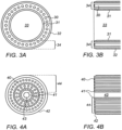
- Figs. 3A and 3B and to Figs. 4A and 4B show schematically further implementations of hybrid ablation catheters of the present disclosure, which illustrate how the catheters can be used to selectively ablate atheromatous material from the blood vessels, while reducing the danger of perforating the blood vessel wall.
- the structures of the hybrid catheters shown in these drawings have the common feature that besides the fiber bundles emitting the ablating laser pulses, the blunt distal ends of the tubular elements enclosing the fiber bundles are also constructed such that they contribute to the operation of the catheters.
- the distal ends of the tubular structures are specifically constructed having non-sharp ends, called hereinbelow blunt mechanical blades, so that they do not unintentionally dissect the blood vessel walls.
- Figs. 3A and 3B show respectively a schematic end view and a cross sectional side view of an exemplary annular hybrid catheter which can selectively ablate atheromatous tissue substantially more readily than the walls of blood vessels, such that lead extraction can be more safely performed.
- the laser energy is transmitted to the distal end of the catheter through a bundle of optical fibers 30 embedded within an adhesive matrix, in the form of an annulus having a large central clear area 33.
- the annulus of optical fibers 30 is bounded on its inner side by a thin tube 31, which constitutes the inner blunt mechanical blade, and on its outer side by another thin tube 32, which constitutes the outer blunt mechanical blade.
- the distance between the innermost edge of the inner tube 31 and the outermost edge of the outer tube 32 is known as the effective wall thickness 34 of the catheter, or the distal tip.
- the catheter is inserted into the blood vessel over the lead to be extracted, such that the lead is situated in the central annular area 33.
- the laser pulse energy is applied to the fiber bundle 30, typically in the ultraviolet region of 320 to 400 nm, and having a fluence of 50 to 80 mJ/mm 2 , accompanied by a force applied distally to the catheter, enables the catheter to proceed in a distal direction debulking the lead from the walls of the blood vessel, without damaging the walls of the blood vessel, as explained in the summary section hereinabove.
- the critical parameter for the success of this process is based on the trade-off between two energetic processes taking place at the tissue interaction plane at the tip of the catheter.
- the total area of the fiber cores emitting the laser pulses known as the active emitting area
- the active emitting area is providing the ablating energy in order to degrade the atheromatous material, while the mechanical force exerted distally on the catheter, which pushes and peels off the degraded material mechanically, operates through what is termed the distal tip area, which includes all of the mechanical parts of the distal face of the catheter, including the inner and outer blunt mechanical blade areas, and the mechanical area of the fiber adhesive matrix, but not the hollow central area.
- the wall thickness or distal tip 34 of such catheters is typically in the range of 200 to 400 ⁇ m, , such that the ratio of the fiber core area to the distal tip area of the catheter is between 25% and 50%. The most effective ratio is in the range of 30% to 40%.
- the distal force applied to the catheter may be in the region of 0.5 kg and even up to 2 kg.
- Figs. 4A and 4B now show in end view and in cross sectional side views, an exemplary hybrid catheter which can selectively ablate plaque from atherosclerotic blood vessels more safely, such as for use in PAD treatment.
- This type of catheter differs from that shown in Figs. 3A and 3B in that the fiber optical bundle 40 fills the majority of the central region of the catheter, leaving only a small central opening 43 inside the inner tube 41, typically left so that the catheter can ride on a guide wire.
- the effective wall thickness 44 of this hybrid catheter is the distance between the outer surface of the outer tube 42 and the inner wall of the inner tube 41, and is typically in the range of 400 to 1,200 ⁇ m.
- the ratio of the fiber core area to the distal tip area of the catheter is between 25% and 50%. Because of the nature of the PAD treatment, more care is required in pushing the catheter through for instance a curved blood vessel, such that the force may be smaller, but at least 100gm.
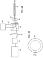
- Fig. 5A illustrates schematically an arrangement for calibrating the hybrid catheters described in this disclosure. Calibration is necessary prior to the operation in order to verify the fluence and the repetition rate of the laser energy that is emitted from the catheters.
- the system shown in Fig. 5A differs from prior art methods in that it enables the internal calibration of the catheter, while it is in use, and also enables detection of a failure of the system while it is operating.
- the incident beam from the laser 50 is directed through a beam polarizer 51, which outputs the beam as P-polarized, as marked in Fig. 5A .
- the P-polarized beam is input to a polarizing beam splitter 53, from which it emerges undeflected.
- the P-polarized beam is then input through a quarter wave plate 54, which converts its polarization to circular.
- This circularly polarized beam then enters the fiber 55, passing therethrough by total internal reflections (TIR), and the majority of the energy is emitted from the output facet at the distal end of the fiber, for use in the ablation procedure 59.
- TIR total internal reflections
- the power measured by the detector 58 is that due only to reflection from the output facet, such that differentiation can be made between reflections from these two facets.
- the spatial filter may conveniently be a thin film polarizer (TFP) as illustrated in Fig 5B , wherein The TFP 60 is coated at its peripheral edges 61, such that those edges diverged the reflected beam from the output facet to the detector 58, while the central region 62 of the TFP 60 is uncoated and therefore the smaller divergence reflection from the input facet passes through that central uncoated window, and does not reach the detector.
- TFP thin film polarizer
- a cap may be placed over the distal tip of the catheter, with the inside of the cap is coated with reflective coating in order to enhance the signal that is reflected from the distal facets of the fibers.
- the cap may be coated with a fluorescent material that changes the wavelength of the output reflected beam, and by use of an optical filter, its separation from the entrance facet reflection is achieved.
- the cap may be sterilized together with the catheter.
- the cap may also be covered with material, polyamide for example, that gives a vocal indication when energy above specified level strikes it.
- the cup can be covered with material that changes it color when exposed to the radiation of the laser.
- the above-described calibration procedure can be performed while the fiber is rolled up inside its packaging, keeping the bend radius of the fiber known and constant, so that the percent of energy reflected back from the output facet does not change.
- the entrance facet is not coated, and the detector will measure both the energy reflected from the input and output facets.
- the system can be internally calibrated, without connecting the catheter, wherein there is a lid that is moved aside when the catheter is connected, and is closed when the catheter is moved out.
- This lid is mirror coated at the side that is pointing to the laser, and the energy reflected from this mirror coating is folded by the polarized beam splitter and can be measured in the detector.
- the described method of calibrating such catheters also enables real time monitoring of the ablation process, by measuring the reflected energy in the system detector during the procedure and informing the user about energy degradation due to fiber damage.
- Hollowed capillaries 65 may be incorporated between the optical fibers 66 and allow the flow of the saline to the point of contact of the distal tip of the catheter 63 and the ablated tissue.
- the hollowed capillaries 65 may extend from the handle to the distal tip of the catheter 63, and the saline is injected through the proximal side of the hollowed capillaries 65.
- a large hollowed capillary 67 may be connected to the small and short hollowed capillaries 65 that are placed at the distal tip of the catheter 63.
- FIG. 6C Another embodiment is illustrated in Fig 6C .
- the Saline in injected in the space wherein the optical fibers 66 are located, between the inner tube 69 and the outer tube 68.
- the small capillaries 65 are located at the distal tip of the catheter, in between the glue 72, the inner blade 71 and the outer blade 70.
- the capillaries 65 enable dripping of the Saline through the distal tip of the catheter.
- the present invention uses example from blood vessels, the utility is relevant for other medical indications requiring controlled resection of tissue such as Barrett's esophagus, flat polyps' removal in the intestine or in urology and gynecology applications such as debulking in BPH.
Landscapes
- Physics & Mathematics (AREA)
- Health & Medical Sciences (AREA)
- Optics & Photonics (AREA)
- Engineering & Computer Science (AREA)
- Electromagnetism (AREA)
- Life Sciences & Earth Sciences (AREA)
- Biomedical Technology (AREA)
- General Physics & Mathematics (AREA)
- Surgery (AREA)
- Nuclear Medicine, Radiotherapy & Molecular Imaging (AREA)
- Public Health (AREA)
- Veterinary Medicine (AREA)
- Animal Behavior & Ethology (AREA)
- General Health & Medical Sciences (AREA)
- Plasma & Fusion (AREA)
- Medical Informatics (AREA)
- Molecular Biology (AREA)
- Vascular Medicine (AREA)
- Otolaryngology (AREA)
- Heart & Thoracic Surgery (AREA)
- Pathology (AREA)
- Radiology & Medical Imaging (AREA)
- Nonlinear Science (AREA)
- Chemical & Material Sciences (AREA)
- Crystallography & Structural Chemistry (AREA)
- Laser Surgery Devices (AREA)
Claims (14)
- System für eine Ablation eines Bereichs eines Gewebes, das System umfassend:einen Laser (50), der einen Strahl von Laserimpulsen emittiert,mindestens eine optische Faser (55), umfassend eine Eingangsfacette und eine Ausgangsfacette;wobei die mindestens eine optische Faser konfiguriert ist, um durch Kopplungsoptik mit dem Laser gekoppelt zu werden;derart, dass ein Energiefluss von der mindestens einen optischen Faser emittiert wird;einen Strahlteiler (53), der zwischen dem Laser und der mindestens einen Faser positioniert ist;
undeinen linearen Polarisator (51), der in dem optischen Pfad des Strahls derart angeordnet ist, dass der Strahl eine vorbestimmte lineare Polarisation vor einem Auftreffen auf den Strahlteiler aufweist;eine Viertelwellenplatte (54), die zwischen dem Strahlteiler und der Eingangsfacette der mindestens einen Faser derart angeordnet ist, dass der Strahlteiler die vorbestimmte Fraktion in Richtung des Detektors leitet; undeinen Detektor (58), der hinter dem Strahlteiler in einer Position senkrecht zu der Richtung des Strahls positioniert ist, der durch den Laser emittiert wird;wobei der Detektor eine vorbestimmte Fraktion des Strahls empfängt, wobei die Fraktion von der Eingangsfacette und/oder der Ausgangsfacette derart zurückgesendet wird, dass der Energiefluss, der durch die mindestens eine optische Faser abgegeben wird, bestimmt werden kann. - Laserablationssystem nach Anspruch 1, wobei die Eingangsfacette eine Antireflexionsbeschichtung umfasst und wobei die Laserenergie Laserenergie ist, die nur von der Ausgangsfacette zurückgesendet wird.
- Laserablationssystem nach Anspruch 1, ferner umfassend eine Kappe, die über einer distalen Spitze der optischen Faser platziert ist.
- Laserablationssystem nach Anspruch 3, wobei die Kappe mit einer Reflexionsbeschichtung beschichtet ist, die konfiguriert ist, um den Laserstrahl zurückzusenden, der durch den Laser emittiert wird.
- Laserablationssystem nach Anspruch 4, wobei die Kappe ein Fluoreszenzmaterial umfasst, das konfiguriert ist, um die Wellenlänge des Strahls zu ändern, der durch den Laser emittiert wird.
- Laserablationssystem nach Anspruch 5, ferner umfassend einen optischen oder räumlichen Filter, der konfiguriert ist, um den Strahl, der von der Kappe zurückgesendet wird, von dem Strahl, der von der Eingangsfacette zurückgesendet wird, zu trennen.
- Laserablationssystem nach Anspruch 1, wobei der Detektor konfiguriert ist, um den Laserstrahl, der von der Eingangsfacette und/oder Ausgangsfacette zurückgesendet wird, während des Ablationsvorgangs zu erfassen.
- Laserablationssystem nach einem der vorstehenden Ansprüche, wobei der Laser ein hochmultimodaler Laser ist, das System ferner umfassend eine Halbwellenplatte und wobei der Strahlteiler ein Polarisationsstrahlteiler ist, um den Strahl in zwei Komponententeile zu spalten, einen S-polarisierten und einen P-polarisierten Teil.
- Laserablationssystem nach Anspruch 8, wobei der Strahlteiler ein kubischer Strahlteiler ist.
- Laserablationssystem nach Anspruch 9, wobei der S-polarisierte Strahl um 90° auslenkbar ist, während der P-polarisierte Strahl durch den kubischen Strahlteiler ohne Ablenkung hindurchführbar ist.
- Laserablationssystem nach einem der Ansprüche 8 bis 10, ferner umfassend zwei volle Reflektorspiegel und einen zweiten Polarisationsstrahlteiler und eine Koppellinse.
- Laserablationssystem nach Anspruch 11, wobei die S-Polarisation auf einem optischen Pfad länger als die der P-Polarisation förderbar ist, und wobei die S- und die P-Polarisationsstrahlen mittels der zwei vollen Reflektorspiegel um 180° reflektierbar sind und wobei die S- und die P-Polarisationsstrahlen mittels des zweiten Polarisationsstrahlteilers 29 rekombinierbar und mittels der Koppellinse koppelbar zu Koppeln sind.
- Laserablationssystem nach Anspruch 11, ferner umfassend eine Linse, die in einem längeren optischen Pfad der optischen Pfade der S- und der P-Polarisationsstrahlen angeordnet ist, um eine Strahltaille auf solche Weise abzubilden, dass sich die Taillen der zwei Strahlen, die die zwei unterschiedlichen optischen Pfade durchqueren, beide an einer Eingangsfacette der optischen Faser befinden.
- Laserablationssystem nach Anspruch 1, ferner umfassend, wobei die vorbestimmte Fraktion des Strahls, der von der mindestens einen der Eingangsfacetten oder der Ausgangsfacetten reflektiert wird, eine lineare Polarisation orthogonal zu der des Strahleingangs in die mindestens eine Faser aufweist.
Priority Applications (1)
| Application Number | Priority Date | Filing Date | Title |
|---|---|---|---|
| EP21180564.3A EP3915503A3 (de) | 2014-05-18 | 2015-05-18 | System zur gewebeablation mit gepulstem laser |
Applications Claiming Priority (4)
| Application Number | Priority Date | Filing Date | Title |
|---|---|---|---|
| US201461994904P | 2014-05-18 | 2014-05-18 | |
| US201462006389P | 2014-06-02 | 2014-06-02 | |
| PCT/IL2015/050529 WO2015177790A1 (en) | 2014-05-18 | 2015-05-18 | System for tissue ablation using pulsed laser |
| EP15796468.5A EP3145430B1 (de) | 2014-05-18 | 2015-05-18 | System zur gewebeablation mit gepulstem laser |
Related Parent Applications (2)
| Application Number | Title | Priority Date | Filing Date |
|---|---|---|---|
| EP15796468.5A Division EP3145430B1 (de) | 2014-05-18 | 2015-05-18 | System zur gewebeablation mit gepulstem laser |
| EP15796468.5A Division-Into EP3145430B1 (de) | 2014-05-18 | 2015-05-18 | System zur gewebeablation mit gepulstem laser |
Related Child Applications (2)
| Application Number | Title | Priority Date | Filing Date |
|---|---|---|---|
| EP21180564.3A Division EP3915503A3 (de) | 2014-05-18 | 2015-05-18 | System zur gewebeablation mit gepulstem laser |
| EP21180564.3A Division-Into EP3915503A3 (de) | 2014-05-18 | 2015-05-18 | System zur gewebeablation mit gepulstem laser |
Publications (4)
| Publication Number | Publication Date |
|---|---|
| EP3552571A2 EP3552571A2 (de) | 2019-10-16 |
| EP3552571A3 EP3552571A3 (de) | 2019-11-27 |
| EP3552571B1 true EP3552571B1 (de) | 2024-09-25 |
| EP3552571B8 EP3552571B8 (de) | 2024-10-30 |
Family
ID=54553515
Family Applications (3)
| Application Number | Title | Priority Date | Filing Date |
|---|---|---|---|
| EP21180564.3A Pending EP3915503A3 (de) | 2014-05-18 | 2015-05-18 | System zur gewebeablation mit gepulstem laser |
| EP19177412.4A Active EP3552571B8 (de) | 2014-05-18 | 2015-05-18 | System zur gewebeablation mit gepulstem laser |
| EP15796468.5A Active EP3145430B1 (de) | 2014-05-18 | 2015-05-18 | System zur gewebeablation mit gepulstem laser |
Family Applications Before (1)
| Application Number | Title | Priority Date | Filing Date |
|---|---|---|---|
| EP21180564.3A Pending EP3915503A3 (de) | 2014-05-18 | 2015-05-18 | System zur gewebeablation mit gepulstem laser |
Family Applications After (1)
| Application Number | Title | Priority Date | Filing Date |
|---|---|---|---|
| EP15796468.5A Active EP3145430B1 (de) | 2014-05-18 | 2015-05-18 | System zur gewebeablation mit gepulstem laser |
Country Status (6)
| Country | Link |
|---|---|
| US (9) | US20170079718A1 (de) |
| EP (3) | EP3915503A3 (de) |
| CN (2) | CN106794043B (de) |
| ES (1) | ES2991421T3 (de) |
| IL (2) | IL248743B (de) |
| WO (1) | WO2015177790A1 (de) |
Families Citing this family (65)
| Publication number | Priority date | Publication date | Assignee | Title |
|---|---|---|---|---|
| CA2862611C (en) | 2011-02-24 | 2020-11-03 | Eximo Medical Ltd. | Hybrid catheter for tissue resection |
| US12514456B2 (en) | 2013-01-31 | 2026-01-06 | Eximo Medical Ltd. | System and methods for lesion characterization in blood vessels |
| ES2991421T3 (es) * | 2014-05-18 | 2024-12-03 | Eximo Medical Ltd | Sistema para ablación de tejidos usando láser pulsado |
| US11272983B2 (en) * | 2016-02-03 | 2022-03-15 | Cyclone Biosciences, Llc | Process and system for reducing laser damage to surgical instruments |
| AU2017217247A1 (en) * | 2016-02-10 | 2018-09-27 | Helium 3 Resources Pty Ltd | A therapeutic method and device therefor |
| CN109414292A (zh) | 2016-05-05 | 2019-03-01 | 爱克斯莫医疗有限公司 | 用于切除和/或消融不需要的组织的装置和方法 |
| EP3281598A1 (de) * | 2016-08-09 | 2018-02-14 | Koninklijke Philips N.V. | Lichtbasierte hautbehandlungsvorrichtung und -verfahren |
| JP2020508750A (ja) * | 2017-02-28 | 2020-03-26 | アルコン インコーポレイティド | 関節式ビーム分離によるマルチファイバーマルチスポットレーザプローブ |
| CN110868952B (zh) * | 2017-07-13 | 2023-08-08 | 皇家飞利浦有限公司 | 使用衍射光学元件的激光发生器 |
| US12239371B2 (en) * | 2018-08-09 | 2025-03-04 | Koninklijke Philips N.V. | Treatment mode selection systems and laser catheter systems including same |
| CN111035451B (zh) * | 2018-10-11 | 2021-04-23 | 庞兴学 | 激光导管 |
| CN111035450B (zh) * | 2018-10-11 | 2021-04-23 | 庞兴学 | 一种激光导管 |
| JP2022514614A (ja) * | 2018-12-21 | 2022-02-14 | アドバンスト オステオトミー ツールズ - エーオーティー アーゲー | レーザ源、レーザデバイス、及び組織を切除する方法 |
| CN109498153A (zh) * | 2018-12-29 | 2019-03-22 | 深圳市中科微光医疗器械技术有限公司 | 一种血管内激光斑块消融系统及方法 |
| EP3685781B8 (de) | 2019-01-24 | 2022-06-29 | Erbe Elektromedizin GmbH | Vorrichtung zur gewebekoagulation |
| US11933959B2 (en) * | 2019-02-01 | 2024-03-19 | Thorlabs, Inc. | High dynamic range imaging |
| JP7516354B2 (ja) * | 2019-03-29 | 2024-07-16 | 古河電気工業株式会社 | 光ファイバの状態検知システム |
| US11234866B2 (en) | 2019-04-19 | 2022-02-01 | Elios Vision, Inc. | Personalization of excimer laser fibers |
| US11103382B2 (en) | 2019-04-19 | 2021-08-31 | Elt Sight, Inc. | Systems and methods for preforming an intraocular procedure for treating an eye condition |
| US11389239B2 (en) | 2019-04-19 | 2022-07-19 | Elios Vision, Inc. | Enhanced fiber probes for ELT |
| US11672475B2 (en) | 2019-04-19 | 2023-06-13 | Elios Vision, Inc. | Combination treatment using ELT |
| US11076933B2 (en) | 2019-04-19 | 2021-08-03 | Elt Sight, Inc. | Authentication systems and methods for an excimer laser system |
| US11717139B2 (en) | 2019-06-19 | 2023-08-08 | Bolt Medical, Inc. | Plasma creation via nonaqueous optical breakdown of laser pulse energy for breakup of vascular calcium |
| WO2020256898A1 (en) | 2019-06-19 | 2020-12-24 | Boston Scientific Scimed, Inc. | Balloon surface photoacoustic pressure wave generation to disrupt vascular lesions |
| US12402946B2 (en) | 2019-06-19 | 2025-09-02 | Boston Scientific Scimed, Inc. | Breakdown of laser pulse energy for breakup of vascular calcium |
| US11660427B2 (en) | 2019-06-24 | 2023-05-30 | Boston Scientific Scimed, Inc. | Superheating system for inertial impulse generation to disrupt vascular lesions |
| US12280223B2 (en) | 2019-06-26 | 2025-04-22 | Boston Scientific Scimed, Inc. | Focusing element for plasma system to disrupt vascular lesions |
| US11583339B2 (en) | 2019-10-31 | 2023-02-21 | Bolt Medical, Inc. | Asymmetrical balloon for intravascular lithotripsy device and method |
| US12102384B2 (en) | 2019-11-13 | 2024-10-01 | Bolt Medical, Inc. | Dynamic intravascular lithotripsy device with movable energy guide |
| US12274497B2 (en) | 2019-12-18 | 2025-04-15 | Bolt Medical, Inc. | Multiplexer for laser-driven intravascular lithotripsy device |
| US12446961B2 (en) | 2020-02-10 | 2025-10-21 | Bolt Medical, Inc. | System and method for pressure monitoring within a catheter system |
| US11672599B2 (en) | 2020-03-09 | 2023-06-13 | Bolt Medical, Inc. | Acoustic performance monitoring system and method within intravascular lithotripsy device |
| US20210275249A1 (en) * | 2020-03-09 | 2021-09-09 | Boston Scientific Scimed, Inc. | Laser pulse shaping to enhance conversion efficiency and protect fiber optic delivery system for disruption of vascular calcium |
| WO2021188233A1 (en) | 2020-03-18 | 2021-09-23 | Bolt Medical, Inc. | Optical analyzer assembly and method for intravascular lithotripsy device |
| US20210353359A1 (en) * | 2020-05-12 | 2021-11-18 | Bolt Medical, Inc. | Active alignment system and method for optimizing optical coupling of multiplexer for laser-driven intravascular lithotripsy device |
| US12295654B2 (en) | 2020-06-03 | 2025-05-13 | Boston Scientific Scimed, Inc. | System and method for maintaining balloon integrity within intravascular lithotripsy device with plasma generator |
| US12207870B2 (en) | 2020-06-15 | 2025-01-28 | Boston Scientific Scimed, Inc. | Spectroscopic tissue identification for balloon intravascular lithotripsy guidance |
| US12376904B1 (en) | 2020-09-08 | 2025-08-05 | Angiodynamics, Inc. | Dynamic laser stabilization and calibration system |
| KR102572940B1 (ko) * | 2020-10-30 | 2023-09-01 | 김영한 | 광에너지 전달을 위한 카테터 내관 |
| US12016610B2 (en) | 2020-12-11 | 2024-06-25 | Bolt Medical, Inc. | Catheter system for valvuloplasty procedure |
| WO2022154954A1 (en) | 2021-01-12 | 2022-07-21 | Bolt Medical, Inc. | Balloon assembly for valvuloplasty catheter system |
| US11672585B2 (en) | 2021-01-12 | 2023-06-13 | Bolt Medical, Inc. | Balloon assembly for valvuloplasty catheter system |
| CN113017827B (zh) * | 2021-03-02 | 2022-05-20 | 哈尔滨医科大学 | 一种集成超声成像与激光消蚀术的导管系统 |
| CN113040901B (zh) * | 2021-03-16 | 2022-03-08 | 哈尔滨医科大学 | 一种附加冲击波球囊的激光消蚀导管 |
| CN113040903A (zh) * | 2021-03-23 | 2021-06-29 | 哈尔滨医科大学 | 激光消蚀系统 |
| CN113116516B (zh) * | 2021-04-01 | 2024-09-03 | 广东迪光医学科技有限公司 | 激光耦合装置 |
| KR20240016979A (ko) * | 2021-05-07 | 2024-02-06 | 데네브 메디칼, 에스.엘. | 생물학적 조직을 안전하게 절편화하기 위한 장치 |
| US11648057B2 (en) | 2021-05-10 | 2023-05-16 | Bolt Medical, Inc. | Optical analyzer assembly with safety shutdown system for intravascular lithotripsy device |
| US11806075B2 (en) | 2021-06-07 | 2023-11-07 | Bolt Medical, Inc. | Active alignment system and method for laser optical coupling |
| CN113662657B (zh) * | 2021-08-26 | 2023-11-14 | 桂林电子科技大学 | 一种具有3d导航功能的介入式血管癌栓消融医疗系统 |
| CN113616329B (zh) * | 2021-08-26 | 2023-11-14 | 桂林电子科技大学 | 一种具有体内3d导航手术功能的介入式激光消融系统 |
| CN115857180A (zh) * | 2021-09-23 | 2023-03-28 | 微创投资控股有限公司 | 集束光纤耦合装置及激光消融系统 |
| US20230149033A1 (en) | 2021-11-16 | 2023-05-18 | Eximo Medical Ltd. | Smart aspiration system |
| US11839391B2 (en) | 2021-12-14 | 2023-12-12 | Bolt Medical, Inc. | Optical emitter housing assembly for intravascular lithotripsy device |
| CN114681054B (zh) * | 2022-05-11 | 2024-12-06 | 广东迪光医学科技有限公司 | 激光消融光源和激光消融装置及发射消融激光的方法 |
| US12038322B2 (en) * | 2022-06-21 | 2024-07-16 | Eximo Medical Ltd. | Devices and methods for testing ablation systems |
| US12409069B2 (en) | 2022-08-30 | 2025-09-09 | Elios Vision, Inc. | Systems and methods for a combined excimer laser and phacoemulsification unit |
| US20240207635A1 (en) * | 2022-12-22 | 2024-06-27 | Hecker Sports Medicine, LLC | Method Of And System For Treatment Of Musculoskeletal Conditions With A Synergistic Combination Of Therapeutic Modalities |
| CN115998420A (zh) * | 2022-12-30 | 2023-04-25 | 深圳市中科融光医疗科技有限公司 | 激光消融光路耦合系统 |
| CN116602628B (zh) * | 2023-07-17 | 2023-11-28 | 江苏京泰全医疗科技有限公司 | 自体荧光组织的探测装置 |
| WO2025073058A1 (en) * | 2023-10-04 | 2025-04-10 | Light Matter Interaction Inc. | Systems, devices and methods for laser-assisted targeted intracorporeal therapy |
| CN118475307B (zh) * | 2023-11-06 | 2025-11-14 | 深圳微量医疗科技有限公司 | 一种光纤合束耦合紫外激光消融系统 |
| KR20250083279A (ko) * | 2023-11-30 | 2025-06-10 | 삼성디스플레이 주식회사 | 표시 장치의 제조 장치 |
| CN118058830A (zh) * | 2024-04-07 | 2024-05-24 | 深圳微量医疗科技有限公司 | 激光消融导管及激光消融系统 |
| CN119326379A (zh) * | 2024-10-24 | 2025-01-21 | 苏州中天医疗器械科技有限公司 | 一种介入血管治疗系统及血管局部成像方法 |
Citations (2)
| Publication number | Priority date | Publication date | Assignee | Title |
|---|---|---|---|---|
| JPS6159236A (ja) * | 1984-08-30 | 1986-03-26 | Fujikura Ltd | 単一モ−ド光フアイバ用光パルス試験器 |
| US5219345A (en) * | 1990-03-30 | 1993-06-15 | Health Research, Inc. | Backscatter monitoring system |
Family Cites Families (322)
| Publication number | Priority date | Publication date | Assignee | Title |
|---|---|---|---|---|
| US4273127A (en) * | 1978-10-12 | 1981-06-16 | Research Corporation | Method for cutting and coagulating tissue |
| US4288316A (en) * | 1980-02-21 | 1981-09-08 | Hennessy Michael J | Fecal examining device |
| US4800876A (en) | 1981-12-11 | 1989-01-31 | Fox Kenneth R | Method of and apparatus for laser treatment of body lumens |
| US5989243A (en) | 1984-12-07 | 1999-11-23 | Advanced Interventional Systems, Inc. | Excimer laser angioplasty system |
| US5470330A (en) | 1984-12-07 | 1995-11-28 | Advanced Interventional Systems, Inc. | Guidance and delivery system for high-energy pulsed laser light |
| US4641912A (en) | 1984-12-07 | 1987-02-10 | Tsvi Goldenberg | Excimer laser delivery system, angioscope and angioplasty system incorporating the delivery system and angioscope |
| US4732448A (en) | 1984-12-07 | 1988-03-22 | Advanced Interventional Systems, Inc. | Delivery system for high-energy pulsed ultraviolet laser light |
| US4830460A (en) | 1987-05-19 | 1989-05-16 | Advanced Interventional Systems, Inc. | Guidance system and method for delivery system for high-energy pulsed ultraviolet laser light |
| US5188632A (en) * | 1984-12-07 | 1993-02-23 | Advanced Interventional Systems, Inc. | Guidance and delivery system for high-energy pulsed laser light |
| US20020045811A1 (en) * | 1985-03-22 | 2002-04-18 | Carter Kittrell | Laser ablation process and apparatus |
| US5346488A (en) | 1985-04-08 | 1994-09-13 | The General Hospital Corporation | Laser-induced ablation of atherosclerotic plaque |
| US4695697A (en) * | 1985-12-13 | 1987-09-22 | Gv Medical, Inc. | Fiber tip monitoring and protection assembly |
| US4844062A (en) | 1987-10-23 | 1989-07-04 | Spectranetics Corporation | Rotating fiberoptic laser catheter assembly with eccentric lumen |
| US4955882A (en) | 1988-03-30 | 1990-09-11 | Hakky Said I | Laser resectoscope with mechanical and laser cutting means |
| US4919508A (en) | 1988-08-04 | 1990-04-24 | The Spectranetics Corporation | Fiberoptic coupler |
| US4993412A (en) * | 1989-08-02 | 1991-02-19 | Eclipse Surgical Technologies, Inc. | Method and apparatus for removal of obstructive substance from body channels |
| US5016964A (en) | 1989-10-04 | 1991-05-21 | Spectranetics Corporation | Optical fiber coupler with linear input |
| US4998794A (en) | 1989-10-27 | 1991-03-12 | The Spectranetics Corporation | Meniscus lens for coupling an excimer beam into an optical fiber |
| US4975925A (en) | 1989-11-01 | 1990-12-04 | The Spectranetics Corporation | Unlubricated bearings for gas lasers |
| US5060557A (en) | 1990-01-26 | 1991-10-29 | Penn Ventilator Company, Inc. | Smoke damper blade seal |
| US5916210A (en) | 1990-01-26 | 1999-06-29 | Intraluminal Therapeutics, Inc. | Catheter for laser treatment of atherosclerotic plaque and other tissue abnormalities |
| US5312396A (en) | 1990-09-06 | 1994-05-17 | Massachusetts Institute Of Technology | Pulsed laser system for the surgical removal of tissue |
| US5293872A (en) * | 1991-04-03 | 1994-03-15 | Alfano Robert R | Method for distinguishing between calcified atherosclerotic tissue and fibrous atherosclerotic tissue or normal cardiovascular tissue using Raman spectroscopy |
| US5250045A (en) | 1991-06-11 | 1993-10-05 | The Spectranetics Corporation | Optical fiber catheter with spaced optical fiber |
| JPH06511181A (ja) | 1992-03-18 | 1994-12-15 | ザ・スペクトラネティックス・コーポレーション | 可捩先端を有する繊維光学カテーテル |
| US5263952A (en) | 1992-03-25 | 1993-11-23 | Spectranetics | Two-piece tip for fiber optic catheter |
| EP0574686A2 (de) | 1992-05-13 | 1993-12-22 | The Spectranetics Corporation | Lineares Abtastverfahren und Vorrichtung zur Energieeinkopplung in ein optische Faserbündel |
| US5321783A (en) | 1992-06-16 | 1994-06-14 | Spectranetics Corporation | Mount for optical fibers |
| US5383199A (en) | 1992-07-02 | 1995-01-17 | Advanced Interventional Systems, Inc. | Apparatus and method for optically controlling the output energy of a pulsed laser source |
| EP0597195B1 (de) | 1992-08-18 | 1999-07-21 | The Spectranetics Corporation | Führungsdraht mit Faseroptik |
| EP0656766A4 (de) | 1992-08-26 | 1995-09-27 | Advanced Interventional System | Optischer katheter mit verseilten fasern. |
| US5350377A (en) | 1992-10-26 | 1994-09-27 | Ultrasonic Sensing & Monitoring Systems, Inc. | Medical catheter using optical fibers that transmit both laser energy and ultrasonic imaging signals |
| WO1995022283A1 (en) | 1992-10-26 | 1995-08-24 | Ultrasonic Sensing & Monitoring Systems, Inc. | Catheter using optical fibers to transmit laser and ultrasonic energy |
| US6716210B2 (en) | 1992-12-03 | 2004-04-06 | Lasersight Technologies, Inc. | Refractive surgical laser apparatus and method |
| US5315614A (en) | 1993-05-03 | 1994-05-24 | The Spectranetics Corporation | Apparatus and method for soft focusing energy into an optical fiber array |
| US5456680A (en) | 1993-09-14 | 1995-10-10 | Spectranetics Corp | Fiber optic catheter with shortened guide wire lumen |
| US5395351A (en) | 1993-09-29 | 1995-03-07 | Baxter International Inc. | Self-valving connector and interface system and a method of using same |
| US5423806A (en) * | 1993-10-01 | 1995-06-13 | Medtronic, Inc. | Laser extractor for an implanted object |
| US5429617A (en) | 1993-12-13 | 1995-07-04 | The Spectranetics Corporation | Radiopaque tip marker for alignment of a catheter within a body |
| US5484433A (en) | 1993-12-30 | 1996-01-16 | The Spectranetics Corporation | Tissue ablating device having a deflectable ablation area and method of using same |
| US5395361A (en) | 1994-06-16 | 1995-03-07 | Pillco Limited Partnership | Expandable fiberoptic catheter and method of intraluminal laser transmission |
| US5836940A (en) | 1994-10-25 | 1998-11-17 | Latis, Inc. | Photoacoustic drug delivery |
| US5817144A (en) | 1994-10-25 | 1998-10-06 | Latis, Inc. | Method for contemporaneous application OF laser energy and localized pharmacologic therapy |
| US5624026A (en) | 1995-03-20 | 1997-04-29 | Chernoff; Don | Garment holding device for use with various types of lugggage |
| US5720894A (en) * | 1996-01-11 | 1998-02-24 | The Regents Of The University Of California | Ultrashort pulse high repetition rate laser system for biological tissue processing |
| US5810662A (en) | 1996-04-03 | 1998-09-22 | Tomkins Industries, Inc. | Compact smoke and fire damper with over center latch |
| US5824026A (en) | 1996-06-12 | 1998-10-20 | The Spectranetics Corporation | Catheter for delivery of electric energy and a process for manufacturing same |
| US6053809A (en) | 1997-03-13 | 2000-04-25 | Arceneaux; Henry M. | Smoke detection and ventilation system |
| DE69832079T2 (de) * | 1997-03-14 | 2006-07-20 | Visx Inc., Santa Clara | Kurzgepulster parametrischer mittel-infrarot-generator zur chirurgie |
| US6013072A (en) | 1997-07-09 | 2000-01-11 | Intraluminal Therapeutics, Inc. | Systems and methods for steering a catheter through body tissue |
| US6048349A (en) | 1997-07-09 | 2000-04-11 | Intraluminal Therapeutics, Inc. | Systems and methods for guiding a medical instrument through a body |
| US5951482A (en) | 1997-10-03 | 1999-09-14 | Intraluminal Therapeutics, Inc. | Assemblies and methods for advancing a guide wire through body tissue |
| US6193676B1 (en) | 1997-10-03 | 2001-02-27 | Intraluminal Therapeutics, Inc. | Guide wire assembly |
| US6842639B1 (en) | 1997-10-03 | 2005-01-11 | Intraluminal Therapeutics, Inc. | Method and apparatus for determining neovascular flow through tissue in a vessel |
| US5976124A (en) | 1998-01-05 | 1999-11-02 | Spectranetics Corporation | Phototherapy device and method |
| US6001112A (en) | 1998-04-10 | 1999-12-14 | Endicor Medical, Inc. | Rotational atherectomy device |
| US6547779B2 (en) | 1998-07-22 | 2003-04-15 | Endovasix, Inc. | Flexible flow apparatus and method for the disruption of occlusions |
| US6210400B1 (en) | 1998-07-22 | 2001-04-03 | Endovasix, Inc. | Flexible flow apparatus and method for the disruption of occlusions |
| US6106515A (en) | 1998-08-13 | 2000-08-22 | Intraluminal Therapeutics, Inc. | Expandable laser catheter |
| US6439944B1 (en) | 1998-12-15 | 2002-08-27 | John Edward La Fata | Bubble forming device using iris-like leaf mechanism, and related method |
| US6228076B1 (en) | 1999-01-09 | 2001-05-08 | Intraluminal Therapeutics, Inc. | System and method for controlling tissue ablation |
| US7499756B2 (en) | 1999-04-05 | 2009-03-03 | Spectranetics | Lead locking device and method |
| US8428747B2 (en) | 1999-04-05 | 2013-04-23 | The Spectranetics Corp. | Lead locking device and method |
| US6772014B2 (en) | 2000-12-04 | 2004-08-03 | The Spectranetics Corporation | Lead locking device and method |
| US6539944B1 (en) | 1999-06-11 | 2003-04-01 | Brant D. Watson | Dethrombosis facilitated by vasodilation |
| US7426409B2 (en) | 1999-06-25 | 2008-09-16 | Board Of Regents, The University Of Texas System | Method and apparatus for detecting vulnerable atherosclerotic plaque |
| DE19936904A1 (de) | 1999-07-30 | 2001-02-01 | Biotronik Mess & Therapieg | Katheter |
| US6611720B2 (en) | 1999-08-12 | 2003-08-26 | Irvine Biomedical Inc. | High torque catheter possessing multi-directional deflectability and methods thereof |
| US6622757B2 (en) | 1999-11-30 | 2003-09-23 | Veeder-Root Company | Fueling system vapor recovery and containment performance monitor and method of operation thereof |
| US6440125B1 (en) | 2000-01-04 | 2002-08-27 | Peter Rentrop | Excimer laser catheter |
| US6394976B1 (en) | 2000-01-31 | 2002-05-28 | Intraluminal Therapeutics, Inc. | Catheter for controlling the advancement of a guide wire |
| US6752800B1 (en) | 2000-02-18 | 2004-06-22 | Intraluminal Therapeutics Inc. | Catheter handle for controlling the advancement of a guide wire |
| US6451010B1 (en) | 2000-04-14 | 2002-09-17 | Lumenis Inc. | Zoom handpiece for laser surgery |
| US7083610B1 (en) | 2000-06-07 | 2006-08-01 | Laserscope | Device for irradiating tissue |
| JP3716172B2 (ja) | 2000-11-27 | 2005-11-16 | Necパーソナルプロダクツ株式会社 | ファイルベイの温度制御方法および装置 |
| CA2428872C (en) | 2000-11-28 | 2013-01-08 | Allez Physionix Limited | Systems and methods for making non-invasive physiological assessments |
| US6986764B2 (en) | 2000-12-15 | 2006-01-17 | Laserscope | Method and system for photoselective vaporization of the prostate, and other tissue |
| US6554824B2 (en) | 2000-12-15 | 2003-04-29 | Laserscope | Methods for laser treatment of soft tissue |
| US7927784B2 (en) | 2000-12-20 | 2011-04-19 | Ev3 | Vascular lumen debulking catheters and methods |
| US7450618B2 (en) | 2001-01-30 | 2008-11-11 | Board Of Trustees Operating Michigan State University | Laser system using ultrashort laser pulses |
| US7567596B2 (en) | 2001-01-30 | 2009-07-28 | Board Of Trustees Of Michigan State University | Control system and apparatus for use with ultra-fast laser |
| US6701044B2 (en) | 2001-08-10 | 2004-03-02 | Lightwave Electronics | Solid state laser generating UV radiation for writing fiber bragg gratings |
| EP1458301A1 (de) | 2001-12-28 | 2004-09-22 | The Spectranetics Corporation | Verfahren zur behandlung von gefässverschlüssen mit hemmung der thrombozytenaggregation |
| US6913594B2 (en) | 2001-12-31 | 2005-07-05 | Biosense Webster, Inc. | Dual-function catheter handle |
| US8247731B2 (en) * | 2002-02-25 | 2012-08-21 | Board Of Regents Of The University Of Nebraska | Laser scribing and machining of materials |
| US7050692B2 (en) | 2002-03-29 | 2006-05-23 | The Spectranetics Corporation | Proximal coupler for optical fibers |
| AUPS266302A0 (en) * | 2002-05-30 | 2002-06-20 | Clvr Pty Ltd | Solid state uv laser |
| US6852109B2 (en) | 2002-06-11 | 2005-02-08 | Intraluminal Therapeutics, Inc. | Radio frequency guide wire assembly with optical coherence reflectometry guidance |
| US6893414B2 (en) | 2002-08-12 | 2005-05-17 | Breg, Inc. | Integrated infusion and aspiration system and method |
| US6775447B2 (en) | 2002-09-20 | 2004-08-10 | Fitel Usa Corp. | All fiber low noise supercontinuum source |
| US6951554B2 (en) | 2002-12-16 | 2005-10-04 | Intraluminal Therapeutics Inc. | Deflecting catheter |
| WO2004063632A2 (en) | 2003-01-08 | 2004-07-29 | Nystrom, Inc. | Accoustical smoke vent |
| US7276062B2 (en) | 2003-03-12 | 2007-10-02 | Biosence Webster, Inc. | Deflectable catheter with hinge |
| US6967767B2 (en) | 2003-03-18 | 2005-11-22 | Fitel Usa Corp | Swept wavelength broadband Raman pump source |
| US7303533B2 (en) | 2003-04-10 | 2007-12-04 | Intraluminal Therapeutics, Inc. | Shapeable intraluminal device and method therefor |
| JP4496344B2 (ja) * | 2003-05-01 | 2010-07-07 | 学校法人慶應義塾 | 高強度パルス光を利用した血管内診断または治療用装置 |
| US7330301B2 (en) | 2003-05-14 | 2008-02-12 | Imra America, Inc. | Inexpensive variable rep-rate source for high-energy, ultrafast lasers |
| US20040236228A1 (en) | 2003-05-20 | 2004-11-25 | Richard Stoltz | Camera containing tool |
| US7257302B2 (en) | 2003-06-03 | 2007-08-14 | Imra America, Inc. | In-line, high energy fiber chirped pulse amplification system |
| US7404758B2 (en) | 2003-10-28 | 2008-07-29 | Poly-Clip System Corp. | Apparatus and method to net food products in shirred tubular casing |
| US7022104B2 (en) | 2003-12-08 | 2006-04-04 | Angioscore, Inc. | Facilitated balloon catheter exchange |
| US7566640B2 (en) | 2003-12-15 | 2009-07-28 | Semiconductor Energy Laboratory Co., Ltd. | Method for manufacturing thin film integrated circuit device, noncontact thin film integrated circuit device and method for manufacturing the same, and idtag and coin including the noncontact thin film integrated circuit device |
| AU2003286079A1 (en) | 2003-12-22 | 2005-07-14 | Medela Holding Ag | Drainage apparatus and method |
| US8202279B2 (en) | 2004-03-09 | 2012-06-19 | Cole John P | Follicular extraction punch and method |
| US7167622B2 (en) | 2004-04-08 | 2007-01-23 | Omniguide, Inc. | Photonic crystal fibers and medical systems including photonic crystal fibers |
| US7959608B2 (en) | 2004-04-27 | 2011-06-14 | The Spectranetics Corporation | Thrombectomy and soft debris removal device |
| US8920402B2 (en) | 2004-04-27 | 2014-12-30 | The Spectranetics Corporation | Thrombectomy and soft debris removal device |
| US20050251116A1 (en) * | 2004-05-05 | 2005-11-10 | Minnow Medical, Llc | Imaging and eccentric atherosclerotic material laser remodeling and/or ablation catheter |
| US7924892B2 (en) | 2004-08-25 | 2011-04-12 | Kla-Tencor Technologies Corporation | Fiber amplifier based light source for semiconductor inspection |
| US7931659B2 (en) | 2004-09-10 | 2011-04-26 | Penumbra, Inc. | System and method for treating ischemic stroke |
| US9655633B2 (en) | 2004-09-10 | 2017-05-23 | Penumbra, Inc. | System and method for treating ischemic stroke |
| WO2006033989A2 (en) | 2004-09-17 | 2006-03-30 | The Spectranetics Corporation | Apparatus and methods for directional delivery of laser energy |
| US8628519B2 (en) | 2004-09-17 | 2014-01-14 | The Spectranetics Corporation | Rapid exchange bias laser catheter design |
| US8545488B2 (en) | 2004-09-17 | 2013-10-01 | The Spectranetics Corporation | Cardiovascular imaging system |
| US9119907B2 (en) | 2004-09-21 | 2015-09-01 | Zoll Medical Corporation | Digitally controlled aspirator |
| US20060229515A1 (en) | 2004-11-17 | 2006-10-12 | The Regents Of The University Of California | Fiber optic evaluation of tissue modification |
| US7508853B2 (en) | 2004-12-07 | 2009-03-24 | Imra, America, Inc. | Yb: and Nd: mode-locked oscillators and fiber systems incorporated in solid-state short pulse laser systems |
| SE0500063L (sv) | 2005-01-11 | 2006-07-12 | Moelnlycke Health Care Ab | Komponent för att täta runt en öppning i huden |
| US7528342B2 (en) * | 2005-02-03 | 2009-05-05 | Laserfacturing, Inc. | Method and apparatus for via drilling and selective material removal using an ultrafast pulse laser |
| US20060241495A1 (en) * | 2005-03-23 | 2006-10-26 | Eastman Kodak Company | Wound healing monitoring and treatment |
| US7856985B2 (en) | 2005-04-22 | 2010-12-28 | Cynosure, Inc. | Method of treatment body tissue using a non-uniform laser beam |
| US20060264905A1 (en) | 2005-05-02 | 2006-11-23 | Pulsar Vascular, Inc. | Improved Catheters |
| EP1887940B1 (de) | 2005-05-06 | 2013-06-26 | Vasonova, Inc. | Vorrichtung zur führung und positionierung eines endovaskulären geräts |
| US20070005030A1 (en) | 2005-06-21 | 2007-01-04 | Hopkins Mark A | Aspiration control via flow or impedance |
| US20070016177A1 (en) * | 2005-07-14 | 2007-01-18 | Boris Vaynberg | Laser ablation apparatus useful for hard tissue removal |
| US20160001064A1 (en) | 2005-07-22 | 2016-01-07 | The Spectranetics Corporation | Endocardial lead cutting apparatus |
| US7787506B1 (en) | 2005-07-26 | 2010-08-31 | Coherent, Inc. | Gain-switched fiber laser system |
| US8097012B2 (en) | 2005-07-27 | 2012-01-17 | The Spectranetics Corporation | Endocardial lead removing apparatus |
| US7993359B1 (en) | 2005-07-27 | 2011-08-09 | The Spectrametics Corporation | Endocardial lead removing apparatus |
| US7430352B2 (en) | 2005-07-29 | 2008-09-30 | Aculight Corporation | Multi-segment photonic-crystal-rod waveguides for amplification of high-power pulsed optical radiation and associated method |
| US7391561B2 (en) | 2005-07-29 | 2008-06-24 | Aculight Corporation | Fiber- or rod-based optical source featuring a large-core, rare-earth-doped photonic-crystal device for generation of high-power pulsed radiation and method |
| US7809222B2 (en) | 2005-10-17 | 2010-10-05 | Imra America, Inc. | Laser based frequency standards and their applications |
| US7651503B1 (en) | 2005-10-26 | 2010-01-26 | The Spectranetics Corporation | Endocardial lead cutting apparatus |
| US7519253B2 (en) | 2005-11-18 | 2009-04-14 | Omni Sciences, Inc. | Broadband or mid-infrared fiber light sources |
| GB2434483A (en) | 2006-01-20 | 2007-07-25 | Fianium Ltd | High-Power Short Optical Pulse Source |
| US8189971B1 (en) | 2006-01-23 | 2012-05-29 | Raydiance, Inc. | Dispersion compensation in a chirped pulse amplification system |
| US8414568B2 (en) | 2006-04-04 | 2013-04-09 | The Spectranetics Corporation | Laser-assisted guidewire having a variable stiffness shaft |
| US7929579B2 (en) * | 2006-08-02 | 2011-04-19 | Cynosure, Inc. | Picosecond laser apparatus and methods for its operation and use |
| US20080082091A1 (en) | 2006-09-10 | 2008-04-03 | Vladimir Rubtsov | Fiber optic tissue ablation |
| US8366690B2 (en) | 2006-09-19 | 2013-02-05 | Kci Licensing, Inc. | System and method for determining a fill status of a canister of fluid in a reduced pressure treatment system |
| US8852219B2 (en) | 2006-10-04 | 2014-10-07 | Bayer Medical Care Inc. | Interventional catheters having cutter assemblies and differential cutting surfaces for use in such assemblies |
| US8152786B2 (en) | 2006-11-07 | 2012-04-10 | Osprey Medical, Inc. | Collection catheter and kit |
| US8961551B2 (en) | 2006-12-22 | 2015-02-24 | The Spectranetics Corporation | Retractable separating systems and methods |
| US9028520B2 (en) | 2006-12-22 | 2015-05-12 | The Spectranetics Corporation | Tissue separating systems and methods |
| US8104483B2 (en) | 2006-12-26 | 2012-01-31 | The Spectranetics Corporation | Multi-port light delivery catheter and methods for the use thereof |
| US9232959B2 (en) | 2007-01-02 | 2016-01-12 | Aquabeam, Llc | Multi fluid tissue resection methods and devices |
| CN113520315A (zh) | 2007-01-19 | 2021-10-22 | 桑尼布鲁克健康科学中心 | 具有组合的超声和光学成像装置的成像探头 |
| RU2459636C2 (ru) | 2007-02-09 | 2012-08-27 | КейСиАй Лайсензинг Инк. | Устройство и способ лечения участка ткани приложением пониженного давления |
| US8202268B1 (en) | 2007-03-18 | 2012-06-19 | Lockheed Martin Corporation | Method and multiple-mode device for high-power short-pulse laser ablation and CW cauterization of bodily tissues |
| WO2008120141A2 (en) | 2007-03-29 | 2008-10-09 | Koninklijke Philips Electronics N.V. | Method and device for generating a laser beam, a laser treatment device and a laser detection device |
| US7724787B2 (en) | 2007-04-18 | 2010-05-25 | Pyrophotonics Lasers Inc. | Method and system for tunable pulsed laser source |
| US8116341B2 (en) * | 2007-05-31 | 2012-02-14 | Electro Scientific Industries, Inc. | Multiple laser wavelength and pulse width process drilling |
| DE102007028042B3 (de) | 2007-06-14 | 2008-08-07 | Universität Zu Lübeck | Verfahren zur Laserbearbeitung transparenter Materialien |
| US7834331B2 (en) | 2007-08-01 | 2010-11-16 | Board Of Regents, The University Of Texas System | Plasmonic laser nanoablation methods |
| US10342701B2 (en) | 2007-08-13 | 2019-07-09 | Johnson & Johnson Surgical Vision, Inc. | Systems and methods for phacoemulsification with vacuum based pumps |
| JP2010536439A (ja) | 2007-08-17 | 2010-12-02 | コンバテック テクノロジーズ インコーポレイテッド | 人の身体によって排出される液体の吸引システム、およびそのための液体センサー |
| US8070762B2 (en) | 2007-10-22 | 2011-12-06 | Atheromed Inc. | Atherectomy devices and methods |
| US9848952B2 (en) | 2007-10-24 | 2017-12-26 | The Spectranetics Corporation | Liquid light guide catheter having biocompatible liquid light guide medium |
| US9066742B2 (en) | 2007-11-09 | 2015-06-30 | The Spectranetics Corporation | Intra-vascular device with pressure detection capabilities using pressure sensitive material |
| US8582934B2 (en) | 2007-11-12 | 2013-11-12 | Lightlab Imaging, Inc. | Miniature optical elements for fiber-optic beam shaping |
| US8100893B2 (en) | 2007-11-28 | 2012-01-24 | The Spectranetics Corporation | Laser catheter calibrator |
| US8059274B2 (en) | 2007-12-07 | 2011-11-15 | The Spectranetics Corporation | Low-loss polarized light diversion |
| US8062226B2 (en) | 2007-12-17 | 2011-11-22 | Silicon Valley Medical Instruments, Inc. | Telescope for an imaging catheter |
| US20090163899A1 (en) | 2007-12-21 | 2009-06-25 | Spectranetics | Swaged optical fiber catheter tips and methods of making and using |
| US9421065B2 (en) | 2008-04-02 | 2016-08-23 | The Spectranetics Corporation | Liquid light-guide catheter with optically diverging tip |
| US8979828B2 (en) | 2008-07-21 | 2015-03-17 | The Spectranetics Corporation | Tapered liquid light guide |
| US9125562B2 (en) | 2009-07-01 | 2015-09-08 | Avinger, Inc. | Catheter-based off-axis optical coherence tomography imaging system |
| US8114429B2 (en) | 2008-09-15 | 2012-02-14 | Cv Ingenuity Corp. | Local delivery of water-soluble or water-insoluble therapeutic agents to the surface of body lumens |
| US8128951B2 (en) | 2008-09-15 | 2012-03-06 | Cv Ingenuity Corp. | Local delivery of water-soluble or water-insoluble therapeutic agents to the surface of body lumens |
| US8257722B2 (en) | 2008-09-15 | 2012-09-04 | Cv Ingenuity Corp. | Local delivery of water-soluble or water-insoluble therapeutic agents to the surface of body lumens |
| US9198968B2 (en) | 2008-09-15 | 2015-12-01 | The Spectranetics Corporation | Local delivery of water-soluble or water-insoluble therapeutic agents to the surface of body lumens |
| US9510854B2 (en) | 2008-10-13 | 2016-12-06 | Boston Scientific Scimed, Inc. | Thrombectomy catheter with control box having pressure/vacuum valve for synchronous aspiration and fluid irrigation |
| US9408665B2 (en) | 2008-12-12 | 2016-08-09 | The Spectranetics Corporation | Offset catheter |
| US8702773B2 (en) | 2008-12-17 | 2014-04-22 | The Spectranetics Corporation | Eccentric balloon laser catheter |
| EP2385815B1 (de) | 2009-01-07 | 2021-06-23 | Med-Logics, Inc. | Vorrichtungen zur gewebeentfernung |
| KR100940184B1 (ko) | 2009-01-20 | 2010-02-04 | 주식회사 옴니벤트 | 전동 디퓨저 |
| US8073019B2 (en) | 2009-03-02 | 2011-12-06 | Jian Liu | 810 nm ultra-short pulsed fiber laser |
| US8861075B2 (en) | 2009-03-05 | 2014-10-14 | Board Of Trustees Of Michigan State University | Laser amplification system |
| WO2010129075A1 (en) | 2009-04-28 | 2010-11-11 | Avinger, Inc. | Guidewire support catheter |
| WO2010145855A1 (en) | 2009-06-15 | 2010-12-23 | Pantec Biosolutions Ag | Monolithic, side pumped solid-state laser and method for operating the same |
| US9220523B2 (en) | 2009-09-14 | 2015-12-29 | The Spectranetics Corporation | Snaring systems and methods |
| US8104463B2 (en) | 2009-10-19 | 2012-01-31 | Planet Eclipse Limited | Bolt and valve mechanism that uses less gas |
| AU2009354176B2 (en) | 2009-10-22 | 2012-09-06 | Halliburton Energy Services, Inc. | Formation fluid sampling control |
| US9044829B2 (en) | 2009-11-09 | 2015-06-02 | Nlight Photonics Corporation | Fiber laser systems for cold ablation |
| TWI421543B (zh) * | 2009-12-04 | 2014-01-01 | Ind Tech Res Inst | 雙脈衝光產生裝置及其雙脈衝光產生的方法 |
| WO2011084863A2 (en) | 2010-01-07 | 2011-07-14 | Cheetah Omni, Llc | Fiber lasers and mid-infrared light sources in methods and systems for selective biological tissue processing and spectroscopy |
| EP2547392B1 (de) | 2010-03-19 | 2019-01-30 | University of Washington | Drainagesystem für übermässige körperflüssigkeiten |
| US20120302938A1 (en) | 2010-03-19 | 2012-11-29 | University Of Washington | Drainage systems for excess body fluids and associated methods |
| KR20130108067A (ko) | 2010-04-09 | 2013-10-02 | 베식스 바스큘라 인코포레이티드 | 조직 치료를 위한 발전 및 제어 장치 |
| EP2380604A1 (de) | 2010-04-19 | 2011-10-26 | InnoRa Gmbh | Verbesserte Beschichtungsformulierung zum Einritzen oder Schneiden von Ballonkathetern |
| JP5919258B2 (ja) | 2010-04-22 | 2016-05-18 | プリサイス ライト サージカル インコーポレイテッド | フラッシュ蒸発手術システム |
| US8238386B2 (en) | 2010-05-21 | 2012-08-07 | Fraunhofer-Gesellschaft Zur Foerderung Der Angewandten Forschung E.V. | Pulsed light source |
| US9345510B2 (en) | 2010-07-01 | 2016-05-24 | Avinger, Inc. | Atherectomy catheters with longitudinally displaceable drive shafts |
| US8953648B2 (en) | 2010-07-30 | 2015-02-10 | Ben-Gurion University Of The Negev Research & Development Authority | Fiber laser pumping configuration and method |
| WO2012014191A1 (en) * | 2010-07-30 | 2012-02-02 | Ben-Gurion University Of The Negev Research & Development Authority | Fiber laser pumping configuration and method |
| CN103189011A (zh) | 2010-10-27 | 2013-07-03 | 克莱米迪克斯有限责任公司 | 具有增加的热交换面积的冷冻消融装置及相关方法 |
| KR101223239B1 (ko) | 2010-10-28 | 2013-01-21 | 주식회사 페스텍 | 누설량과 보충량의 분리 공급기능을 가지는 급기댐퍼 및 그 제어방법 |
| CA2862611C (en) * | 2011-02-24 | 2020-11-03 | Eximo Medical Ltd. | Hybrid catheter for tissue resection |
| US9413696B2 (en) | 2011-03-30 | 2016-08-09 | Tejas Networks Ltd | System architecture and method for communication between devices over backplane to reduce interface count |
| WO2012141748A1 (en) | 2011-04-11 | 2012-10-18 | Upstream Peripheral Technologies | Needle and guidewire holder |
| US8512326B2 (en) | 2011-06-24 | 2013-08-20 | Arqos Surgical, Inc. | Tissue extraction devices and methods |
| US8956376B2 (en) | 2011-06-30 | 2015-02-17 | The Spectranetics Corporation | Reentry catheter and method thereof |
| US8998936B2 (en) | 2011-06-30 | 2015-04-07 | The Spectranetics Corporation | Reentry catheter and method thereof |
| WO2013003757A2 (en) | 2011-06-30 | 2013-01-03 | The Spectranetics Corporation | Reentry catheter and method thereof |
| DK2720600T3 (da) | 2011-08-03 | 2017-01-02 | Alcon Res Ltd | Bøjelig oftalmisk kirurgisk sonde |
| US20130289546A1 (en) * | 2011-10-04 | 2013-10-31 | Richard Stoltz | Producing higher optical ablative power using multiple pulses having controllable temporal relationships |
| US12096951B2 (en) | 2011-10-05 | 2024-09-24 | Penumbra, Inc. | System and method for treating ischemic stroke |
| US9291683B2 (en) | 2011-10-11 | 2016-03-22 | General Electric Company | Power module protection at start-up |
| WO2013063148A1 (en) | 2011-10-27 | 2013-05-02 | Boston Scientific Scimed, Inc | Mucosal resection device and related methods of use |
| US9238122B2 (en) | 2012-01-26 | 2016-01-19 | Covidien Lp | Thrombectomy catheter systems |
| CN102607717A (zh) * | 2012-02-24 | 2012-07-25 | 桂林电子科技大学 | 激光同源共束相干探测系统和方法 |
| WO2013128330A1 (en) | 2012-02-28 | 2013-09-06 | Koninklijke Philips N.V. | Device for energy-based skin treatment |
| US9216056B2 (en) | 2012-03-02 | 2015-12-22 | Biosense Webster (Israel) Ltd. | Catheter for treatment of atrial flutter having single action dual deflection mechanism |
| KR102136901B1 (ko) | 2012-04-18 | 2020-07-22 | 싸이노슈어, 엘엘씨 | 피코초 레이저 장치 및 그를 사용한 표적 조직의 치료 방법 |
| US8684953B2 (en) | 2012-05-13 | 2014-04-01 | Ozca Engineering Solutions Ltd. | Steering tool |
| WO2013177061A1 (en) | 2012-05-21 | 2013-11-28 | The Regents Of The University Of Colorado, A Body Corporate | Three-dimensional mapping and therapy of prostate cancer |
| EP2865003A1 (de) | 2012-06-26 | 2015-04-29 | Kla-Tencor Corporation | Abtastung in winkelaufgelöster reflektometrie und algorithmische diffraktionsentfernung aus einer optischen messtechnik |
| US9050127B2 (en) | 2012-06-27 | 2015-06-09 | Boston Scientific Limited | Consolidated atherectomy and thrombectomy catheter |
| US9956385B2 (en) | 2012-06-28 | 2018-05-01 | The Spectranetics Corporation | Post-processing of a medical device to control morphology and mechanical properties |
| US9949753B2 (en) | 2012-09-14 | 2018-04-24 | The Spectranetics Corporation | Tissue slitting methods and systems |
| EP2944003B1 (de) | 2013-01-09 | 2020-05-20 | Institut National De La Recherche Scientifique | System und verfahren zur hochintensiven ultrakurzen impulskompression |
| US20150359595A1 (en) | 2013-01-31 | 2015-12-17 | Eximo Medical Ltd. | Hybrid catheter apparatus and methods |
| EP3919116B1 (de) | 2013-01-31 | 2025-06-04 | Digma Medical Ltd. | Systeme zur reduzierung von nervenaktivität in einem organ eines lebewesens |
| US9456672B2 (en) | 2013-03-04 | 2016-10-04 | Donna Condon | Reusable shopping bag storage and dispensing system |
| US9291663B2 (en) | 2013-03-13 | 2016-03-22 | The Spectranetics Corporation | Alarm for lead insulation abnormality |
| US9421035B2 (en) | 2013-03-13 | 2016-08-23 | The Spectranetics Corporation | Method for lead tip removal using a stabilization device |
| US9283040B2 (en) | 2013-03-13 | 2016-03-15 | The Spectranetics Corporation | Device and method of ablative cutting with helical tip |
| US10383691B2 (en) | 2013-03-13 | 2019-08-20 | The Spectranetics Corporation | Last catheter with helical internal lumen |
| US10201387B2 (en) | 2013-03-13 | 2019-02-12 | The Spectranetics Corporation | Laser-induced fluid filled balloon catheter |
| US9731098B2 (en) | 2013-03-13 | 2017-08-15 | The Spectranetics Corporation | Wire centering sheath and method |
| US9456872B2 (en) | 2013-03-13 | 2016-10-04 | The Spectranetics Corporation | Laser ablation catheter |
| US9623211B2 (en) | 2013-03-13 | 2017-04-18 | The Spectranetics Corporation | Catheter movement control |
| US9320530B2 (en) | 2013-03-13 | 2016-04-26 | The Spectranetics Corporation | Assisted cutting balloon |
| US20140277003A1 (en) | 2013-03-13 | 2014-09-18 | The Spectranetics Corporation | Material Capturing Guidewire |
| US9358042B2 (en) | 2013-03-13 | 2016-06-07 | The Spectranetics Corporation | Expandable member for perforation occlusion |
| US9883885B2 (en) | 2013-03-13 | 2018-02-06 | The Spectranetics Corporation | System and method of ablative cutting and pulsed vacuum aspiration |
| US9757200B2 (en) | 2013-03-14 | 2017-09-12 | The Spectranetics Corporation | Intelligent catheter |
| US10201315B2 (en) | 2013-03-15 | 2019-02-12 | Atrium Medical Corporation | Fluid analyzer and associated methods |
| US9980743B2 (en) | 2013-03-15 | 2018-05-29 | The Spectranetics Corporation | Medical device for removing an implanted object using laser cut hypotubes |
| US9878399B2 (en) * | 2013-03-15 | 2018-01-30 | Jian Liu | Method and apparatus for welding dissimilar material with a high energy high power ultrafast laser |
| US9668765B2 (en) | 2013-03-15 | 2017-06-06 | The Spectranetics Corporation | Retractable blade for lead removal device |
| EP2967634B1 (de) | 2013-03-15 | 2019-06-05 | The Spectranetics Corporation | Chirurgisches instrument zum entfernen eines implantierten objekts |
| EP2973894A2 (de) | 2013-03-15 | 2016-01-20 | Cynosure, Inc. | Optische picosekunden-strahlungssysteme und verfahren zur verwendung |
| US9918737B2 (en) | 2013-03-15 | 2018-03-20 | The Spectranetics Corporation | Medical device for removing an implanted object |
| EP2967371B1 (de) | 2013-03-15 | 2024-05-15 | Avinger, Inc. | Vorrichtungen zur durchquerung einer chronischen totalen okklusion mit bildgebung |
| US9278883B2 (en) | 2013-07-15 | 2016-03-08 | Ppg Industries Ohio, Inc. | Glass compositions, fiberizable glass compositions, and glass fibers made therefrom |
| US9645310B2 (en) | 2013-07-25 | 2017-05-09 | B.G. Negev Technologies And Applications Ltd. | Single large mode cladding amplification in active double-clad fibers |
| EP3028353B1 (de) | 2013-08-02 | 2018-07-18 | Koninklijke Philips N.V. | Laservorrichtung mit einstellbarer polarisation |
| US9913688B1 (en) * | 2013-10-01 | 2018-03-13 | Cutera, Inc. | Split pulse picosecond laser for tattoo removal |
| US9962527B2 (en) | 2013-10-16 | 2018-05-08 | Ra Medical Systems, Inc. | Methods and devices for treatment of stenosis of arteriovenous fistula shunts |
| US9676167B2 (en) | 2013-12-17 | 2017-06-13 | Corning Incorporated | Laser processing of sapphire substrate and related applications |
| US9265512B2 (en) | 2013-12-23 | 2016-02-23 | Silk Road Medical, Inc. | Transcarotid neurovascular catheter |
| EP2899643A1 (de) | 2014-01-22 | 2015-07-29 | Harman Becker Automotive Systems GmbH | Multimediaschaltschrank |
| WO2015111046A1 (en) | 2014-01-22 | 2015-07-30 | B.G. Negev Technologies And Applications Ltd., At Ben Gurion University | Multi-pump-pass fiber based lasers and amplifiers |
| US20150238091A1 (en) | 2014-02-24 | 2015-08-27 | Covidien Lp | Photoacoustic monitoring technique with noise reduction |
| US9675371B2 (en) | 2014-03-03 | 2017-06-13 | The Spectranetics Corporation | Dilator sheath set |
| EP3113701B1 (de) | 2014-03-03 | 2020-07-22 | The Spectranetics Corporation | Chirurgische schneidevorrichtung mit mehrfachkonfiguration |
| USD753289S1 (en) | 2014-03-03 | 2016-04-05 | The Spectranetics Corporation | Sheath |
| USD753290S1 (en) | 2014-03-03 | 2016-04-05 | The Spectranetics Corporation | Sheath set |
| US9820761B2 (en) | 2014-03-21 | 2017-11-21 | Route 92 Medical, Inc. | Rapid aspiration thrombectomy system and method |
| US9248221B2 (en) | 2014-04-08 | 2016-02-02 | Incuvate, Llc | Aspiration monitoring system and method |
| US10342606B2 (en) | 2014-05-06 | 2019-07-09 | Cosman Instruments, Llc | Electrosurgical generator |
| ES2991421T3 (es) | 2014-05-18 | 2024-12-03 | Eximo Medical Ltd | Sistema para ablación de tejidos usando láser pulsado |
| US9883877B2 (en) | 2014-05-19 | 2018-02-06 | Walk Vascular, Llc | Systems and methods for removal of blood and thrombotic material |
| US9999468B2 (en) | 2014-05-29 | 2018-06-19 | The Spectranetics Corporation | Remote control switch for a laser system |
| US10149718B2 (en) | 2014-06-11 | 2018-12-11 | The Spectranetics Corporation | Convertible optical and pressure wave ablation system and method |
| EP4559428A3 (de) | 2014-06-12 | 2025-08-20 | Boston Scientific Scimed, Inc. | Verfahren und vorrichtung zur schnellen und selektiven gewebeablation mit kühlung |
| US10266520B2 (en) | 2014-08-08 | 2019-04-23 | The Board Of Trustees Of The University Of Illinois | Bisamidinium-based inhibitors for the treatment of myotonic dystrophy |
| US9821090B2 (en) | 2014-09-30 | 2017-11-21 | The Spectranetics Corporation | Electrodeposition coating for medical devices |
| US10363398B2 (en) | 2014-10-06 | 2019-07-30 | Sanovas Intellectual Property, Llc | Steerable catheter with flexing tip member |
| US9907614B2 (en) | 2014-10-29 | 2018-03-06 | The Spectranetics Corporation | Laser energy delivery devices including laser transmission detection systems and methods |
| FR3031027B1 (fr) | 2014-12-30 | 2017-06-09 | Seb Sa | Procede de decoration d'un article culinaire par traitement mecanique |
| US9884184B2 (en) | 2014-12-30 | 2018-02-06 | The Spectranetics Corporation | Wire hook coupling for lead extension and extraction |
| US9731113B2 (en) | 2014-12-30 | 2017-08-15 | The Spectranetics Corporation | Collapsing coil coupling for lead extension and extraction |
| US10105533B2 (en) | 2014-12-30 | 2018-10-23 | The Spectranetics Corporation | Multi-loop coupling for lead extension and extraction |
| USD742522S1 (en) | 2014-12-30 | 2015-11-03 | The Spectranetics Corporation | Radiopaque tape |
| USD742520S1 (en) | 2014-12-30 | 2015-11-03 | The Spectranetics Corporation | Radiopaque tape |
| USD740946S1 (en) | 2014-12-30 | 2015-10-13 | The Spectranetics Corporation | Radiopaque tape |
| USD742521S1 (en) | 2014-12-30 | 2015-11-03 | The Spectranetics Corporation | Radiopaque tape |
| USD748266S1 (en) | 2014-12-30 | 2016-01-26 | The Spectranetics Corporation | Radiopaque tape |
| US9774161B2 (en) | 2015-02-18 | 2017-09-26 | Toptica Photonics Ag | Fiber delivery of short laser pulses |
| WO2016132349A1 (en) | 2015-02-19 | 2016-08-25 | B. G. Negev Technologies And Applications Ltd., At Ben-Gurion University | Transient bragg gratings in optical waveguides and their applications |
| USD775728S1 (en) | 2015-07-02 | 2017-01-03 | The Spectranetics Corporation | Medical device handle |
| US10702292B2 (en) | 2015-08-28 | 2020-07-07 | Incuvate, Llc | Aspiration monitoring system and method |
| US20170100142A1 (en) | 2015-10-09 | 2017-04-13 | Incuvate, Llc | Systems and methods for management of thrombosis |
| US9774461B2 (en) | 2015-10-21 | 2017-09-26 | Oracle International Corporation | Network switch with dynamic multicast queues |
| US10391275B2 (en) | 2015-11-17 | 2019-08-27 | Potrero Medical, Inc. | Systems, devices and methods for draining and analyzing bodily fluids |
| US10268792B2 (en) | 2015-12-14 | 2019-04-23 | Nxp Usa, Inc. | Designing a density driven integrated circuit |
| US10226263B2 (en) | 2015-12-23 | 2019-03-12 | Incuvate, Llc | Aspiration monitoring system and method |
| CN113350656A (zh) | 2016-02-24 | 2021-09-07 | 禾木(中国)生物工程有限公司 | 柔性增强的神经血管导管 |
| WO2017155994A1 (en) | 2016-03-07 | 2017-09-14 | Antonicelli Alberto | Device, system and method to customize chest drainage therapy |
| US10835111B2 (en) | 2016-07-10 | 2020-11-17 | The Trustees Of Columbia University In The City Of New York | Three-dimensional imaging using swept, confocally aligned planar excitation with an image relay |
| WO2018019829A1 (en) | 2016-07-26 | 2018-02-01 | Neuravi Limited | A clot retrieval system for removing occlusive clot from a blood vessel |
| US11464528B2 (en) | 2016-07-26 | 2022-10-11 | Neuravi Limited | Clot retrieval system for removing occlusive clot from a blood vessel |
| NZ751484A (en) | 2016-08-10 | 2022-07-01 | Australian Inst Of Robotic Orthopaedics Pty Ltd | Robot-assisted laser surgical system |
| WO2018136306A1 (en) | 2017-01-19 | 2018-07-26 | Potrero Medical, Inc | Systems, devices and methods for draining and analyzing bodily fluids |
| US20180207397A1 (en) | 2017-01-23 | 2018-07-26 | Walk Vascular, Llc | Systems and methods for removal of blood and thrombotic material |
| US9803973B1 (en) | 2017-04-13 | 2017-10-31 | Sa08700334 | Ultra-light and ultra-accurate portable coordinate measurement machine |
| WO2018204674A1 (en) | 2017-05-04 | 2018-11-08 | Massachusetts Institute Of Technology | Scanning optical imaging device |
| US11234723B2 (en) | 2017-12-20 | 2022-02-01 | Mivi Neuroscience, Inc. | Suction catheter systems for applying effective aspiration in remote vessels, especially cerebral arteries |
| US11432835B2 (en) | 2017-06-07 | 2022-09-06 | Penumbra, Inc. | Apparatus and methods for clot aspiration |
| CN110868952B (zh) | 2017-07-13 | 2023-08-08 | 皇家飞利浦有限公司 | 使用衍射光学元件的激光发生器 |
| US10236952B1 (en) | 2018-01-17 | 2019-03-19 | B. G. Negev Technologies And Applications Ltd., At Ben-Gurion University | Energy-efficient power and offset allocation of spatial multiplexing in multimode fiber |
| US10716880B2 (en) | 2018-06-15 | 2020-07-21 | Incuvate, Llc | Systems and methods for aspiration and monitoring |
| US11471582B2 (en) | 2018-07-06 | 2022-10-18 | Incept, Llc | Vacuum transfer tool for extendable catheter |
| US11678905B2 (en) | 2018-07-19 | 2023-06-20 | Walk Vascular, Llc | Systems and methods for removal of blood and thrombotic material |
| US10531883B1 (en) | 2018-07-20 | 2020-01-14 | Syntheon 2.0, LLC | Aspiration thrombectomy system and methods for thrombus removal with aspiration catheter |
| CN112533550A (zh) | 2018-07-24 | 2021-03-19 | 半影公司 | 用于受控的凝块抽吸的装置和方法 |
| CN119770761A (zh) | 2018-09-24 | 2025-04-08 | 史赛克公司 | 用于改善抽吸过程中控制响应性的系统和方法 |
| US11400255B1 (en) | 2018-11-15 | 2022-08-02 | Route 92 Medical, Inc. | Aspiration catheter systems and methods of use |
| US11712258B2 (en) | 2018-12-10 | 2023-08-01 | Covidien Lp | Tissue resection systems including fluid outflow management |
| US20200206457A1 (en) | 2018-12-31 | 2020-07-02 | Irras Ab | Fluid Exchange Sensing Catheter |
| US11666382B2 (en) | 2019-08-05 | 2023-06-06 | Gyrus Acmi, Inc. | Laser control using a spectrometer |
| US20210315598A1 (en) | 2019-12-18 | 2021-10-14 | Imperative Care, Inc. | Methods of placing large bore aspiration catheters |
| US12318552B2 (en) | 2020-11-18 | 2025-06-03 | C. R. Bard, Inc. | Collapsible thin-walled valve for drainage control |
| US12109353B2 (en) | 2020-12-04 | 2024-10-08 | C. R. Bard, Inc. | Dynamic pressure response and catheter occlusion system |
| US12128188B2 (en) | 2020-12-21 | 2024-10-29 | C. R. Bard, Inc. | Dynamic pressure response system and method for measuring residual fluid |
| CN114681038B (zh) | 2020-12-31 | 2025-11-25 | 杭州德诺电生理医疗科技有限公司 | 消融装置以及消融系统 |
| WO2022174175A1 (en) | 2021-02-15 | 2022-08-18 | Walk Vascular, Llc | Systems and methods for removal of blood and thrombotic material |
| US12274458B2 (en) | 2021-02-15 | 2025-04-15 | Walk Vascular, Llc | Systems and methods for removal of blood and thrombotic material |
| US11679195B2 (en) | 2021-04-27 | 2023-06-20 | Contego Medical, Inc. | Thrombus aspiration system and methods for controlling blood loss |
| US12038322B2 (en) | 2022-06-21 | 2024-07-16 | Eximo Medical Ltd. | Devices and methods for testing ablation systems |
-
2015
- 2015-05-18 ES ES19177412T patent/ES2991421T3/es active Active
- 2015-05-18 EP EP21180564.3A patent/EP3915503A3/de active Pending
- 2015-05-18 WO PCT/IL2015/050529 patent/WO2015177790A1/en not_active Ceased
- 2015-05-18 EP EP19177412.4A patent/EP3552571B8/de active Active
- 2015-05-18 EP EP15796468.5A patent/EP3145430B1/de active Active
- 2015-05-18 US US15/309,193 patent/US20170079718A1/en not_active Abandoned
- 2015-05-18 CN CN201580037816.4A patent/CN106794043B/zh active Active
- 2015-05-18 CN CN202010105960.XA patent/CN111317565B/zh active Active
-
2016
- 2016-11-03 IL IL248743A patent/IL248743B/en active IP Right Grant
-
2019
- 2019-10-03 US US16/592,725 patent/US10772683B2/en active Active
- 2019-10-17 US US16/655,864 patent/US10792103B2/en active Active
-
2020
- 2020-06-21 IL IL275557A patent/IL275557B/en active IP Right Grant
- 2020-10-21 US US17/076,032 patent/US11116573B2/en active Active
- 2020-12-16 US US17/123,205 patent/US11090117B2/en active Active
-
2021
- 2021-08-06 US US17/395,799 patent/US20210361355A1/en not_active Abandoned
-
2023
- 2023-08-30 US US18/458,516 patent/US12035968B2/en active Active
-
2024
- 2024-06-13 US US18/742,074 patent/US20240407845A1/en active Pending
-
2025
- 2025-01-10 US US19/015,946 patent/US20250143793A1/en active Pending
Patent Citations (2)
| Publication number | Priority date | Publication date | Assignee | Title |
|---|---|---|---|---|
| JPS6159236A (ja) * | 1984-08-30 | 1986-03-26 | Fujikura Ltd | 単一モ−ド光フアイバ用光パルス試験器 |
| US5219345A (en) * | 1990-03-30 | 1993-06-15 | Health Research, Inc. | Backscatter monitoring system |
Also Published As
| Publication number | Publication date |
|---|---|
| EP3915503A2 (de) | 2021-12-01 |
| US20200046430A1 (en) | 2020-02-13 |
| IL248743B (en) | 2020-11-30 |
| IL275557A (en) | 2020-08-31 |
| ES2991421T3 (es) | 2024-12-03 |
| US10772683B2 (en) | 2020-09-15 |
| EP3915503A3 (de) | 2022-03-16 |
| US20210030472A1 (en) | 2021-02-04 |
| EP3552571B8 (de) | 2024-10-30 |
| CN106794043A (zh) | 2017-05-31 |
| US20210361355A1 (en) | 2021-11-25 |
| US12035968B2 (en) | 2024-07-16 |
| EP3552571A3 (de) | 2019-11-27 |
| US10792103B2 (en) | 2020-10-06 |
| EP3145430B1 (de) | 2019-07-03 |
| IL275557B (en) | 2021-05-31 |
| US20240407845A1 (en) | 2024-12-12 |
| EP3145430A4 (de) | 2017-06-07 |
| US11090117B2 (en) | 2021-08-17 |
| CN111317565A (zh) | 2020-06-23 |
| US20210128242A1 (en) | 2021-05-06 |
| US20250143793A1 (en) | 2025-05-08 |
| WO2015177790A1 (en) | 2015-11-26 |
| EP3145430A1 (de) | 2017-03-29 |
| CN106794043B (zh) | 2020-03-13 |
| EP3552571A2 (de) | 2019-10-16 |
| IL248743A0 (en) | 2017-01-31 |
| US11116573B2 (en) | 2021-09-14 |
| US20200038107A1 (en) | 2020-02-06 |
| US20240058059A1 (en) | 2024-02-22 |
| CN111317565B (zh) | 2023-05-09 |
| US20170079718A1 (en) | 2017-03-23 |
Similar Documents
| Publication | Publication Date | Title |
|---|---|---|
| US12035968B2 (en) | System for tissue ablation using pulsed laser | |
| US6129723A (en) | Apparatus and methods for laser-induced superficial alteration of a substrate | |
| EP2818131B1 (de) | Lasersystem zur Behandlung von Körpergewebe | |
| US5151098A (en) | Apparatus for controlled tissue ablation | |
| US20050131400A1 (en) | Endovenous closure of varicose veins with mid infrared laser | |
| CN108175499A (zh) | 一种双波长激光手术装置 | |
| CN113057732A (zh) | 一种激光消蚀术导管 | |
| US10463431B2 (en) | Device for tissue removal | |
| Bonner et al. | Laser sources for angioplasty | |
| CN113040902B (zh) | 激光消蚀导管 | |
| Manni | Dental applications of advanced lasers (DAALtm) | |
| Gudra et al. | Some problems of ultrasonic and laser cutting of biological structures | |
| Denisov et al. | Optimization of the noncontact fiber delivery systems for clinical laser applications | |
| Bowker | Laser-tissue interaction and arterial perforation thresholds in laser angioplasty | |
| Fried et al. | Lasers in Medicine and Surgery | |
| Tittel et al. | Excimer lasers in medicine | |
| Almagor et al. | 4. LASER SOURCES FOR ANGIOPLASTY | |
| Geschwind | plaque by a thermal mechanism. 5-7 Thus, it was thought that laser angioplasty could | |
| Bussiere et al. | Intraoperative XeCl Excimer Laser Coronary Artery Endarterectomy: Clinical Experience. | |
| Fried | Erbium: YAG Laser Incision of Urethral Structures for Treatment of Urinary Incontinence After Prostate Cancer Spray | |
| BUSSIERE et al. | J. zyxwvutsrqponmlkjihgfedcbaZ |
Legal Events
| Date | Code | Title | Description |
|---|---|---|---|
| PUAI | Public reference made under article 153(3) epc to a published international application that has entered the european phase |
Free format text: ORIGINAL CODE: 0009012 |
|
| STAA | Information on the status of an ep patent application or granted ep patent |
Free format text: STATUS: THE APPLICATION HAS BEEN PUBLISHED |
|
| AC | Divisional application: reference to earlier application |
Ref document number: 3145430 Country of ref document: EP Kind code of ref document: P |
|
| AK | Designated contracting states |
Kind code of ref document: A2 Designated state(s): AL AT BE BG CH CY CZ DE DK EE ES FI FR GB GR HR HU IE IS IT LI LT LU LV MC MK MT NL NO PL PT RO RS SE SI SK SM TR |
|
| PUAL | Search report despatched |
Free format text: ORIGINAL CODE: 0009013 |
|
| AK | Designated contracting states |
Kind code of ref document: A3 Designated state(s): AL AT BE BG CH CY CZ DE DK EE ES FI FR GB GR HR HU IE IS IT LI LT LU LV MC MK MT NL NO PL PT RO RS SE SI SK SM TR |
|
| RIC1 | Information provided on ipc code assigned before grant |
Ipc: G02B 6/04 20060101ALN20191022BHEP Ipc: A61N 5/067 20060101ALI20191022BHEP Ipc: A61B 18/22 20060101ALI20191022BHEP Ipc: A61B 18/00 20060101ALN20191022BHEP Ipc: A61N 5/06 20060101ALN20191022BHEP Ipc: A61B 18/24 20060101AFI20191022BHEP |
|
| STAA | Information on the status of an ep patent application or granted ep patent |
Free format text: STATUS: REQUEST FOR EXAMINATION WAS MADE |
|
| 17P | Request for examination filed |
Effective date: 20200528 |
|
| RBV | Designated contracting states (corrected) |
Designated state(s): AL AT BE BG CH CY CZ DE DK EE ES FI FR GB GR HR HU IE IS IT LI LT LU LV MC MK MT NL NO PL PT RO RS SE SI SK SM TR |
|
| STAA | Information on the status of an ep patent application or granted ep patent |
Free format text: STATUS: EXAMINATION IS IN PROGRESS |
|
| 17Q | First examination report despatched |
Effective date: 20200930 |
|
| RIC1 | Information provided on ipc code assigned before grant |
Ipc: A61B 17/32 20060101ALN20231012BHEP Ipc: A61B 17/00 20060101ALN20231012BHEP Ipc: G02B 6/04 20060101ALN20231012BHEP Ipc: A61N 5/06 20060101ALN20231012BHEP Ipc: A61B 18/00 20060101ALN20231012BHEP Ipc: G02B 6/42 20060101ALI20231012BHEP Ipc: A61B 18/22 20060101ALI20231012BHEP Ipc: A61N 5/067 20060101ALI20231012BHEP Ipc: A61B 18/24 20060101AFI20231012BHEP |
|
| GRAP | Despatch of communication of intention to grant a patent |
Free format text: ORIGINAL CODE: EPIDOSNIGR1 |
|
| STAA | Information on the status of an ep patent application or granted ep patent |
Free format text: STATUS: GRANT OF PATENT IS INTENDED |
|
| INTG | Intention to grant announced |
Effective date: 20231122 |
|
| GRAJ | Information related to disapproval of communication of intention to grant by the applicant or resumption of examination proceedings by the epo deleted |
Free format text: ORIGINAL CODE: EPIDOSDIGR1 |
|
| STAA | Information on the status of an ep patent application or granted ep patent |
Free format text: STATUS: EXAMINATION IS IN PROGRESS |
|
| INTC | Intention to grant announced (deleted) | ||
| GRAP | Despatch of communication of intention to grant a patent |
Free format text: ORIGINAL CODE: EPIDOSNIGR1 |
|
| STAA | Information on the status of an ep patent application or granted ep patent |
Free format text: STATUS: GRANT OF PATENT IS INTENDED |
|
| RIC1 | Information provided on ipc code assigned before grant |
Ipc: A61B 17/32 20060101ALN20240418BHEP Ipc: A61B 17/00 20060101ALN20240418BHEP Ipc: G02B 6/04 20060101ALN20240418BHEP Ipc: A61N 5/06 20060101ALN20240418BHEP Ipc: A61B 18/00 20060101ALN20240418BHEP Ipc: G02B 6/42 20060101ALI20240418BHEP Ipc: A61B 18/22 20060101ALI20240418BHEP Ipc: A61N 5/067 20060101ALI20240418BHEP Ipc: A61B 18/24 20060101AFI20240418BHEP |
|
| INTG | Intention to grant announced |
Effective date: 20240503 |
|
| RIC1 | Information provided on ipc code assigned before grant |
Ipc: A61B 17/32 20060101ALN20240424BHEP Ipc: A61B 17/00 20060101ALN20240424BHEP Ipc: G02B 6/04 20060101ALN20240424BHEP Ipc: A61N 5/06 20060101ALN20240424BHEP Ipc: A61B 18/00 20060101ALN20240424BHEP Ipc: G02B 6/42 20060101ALI20240424BHEP Ipc: A61B 18/22 20060101ALI20240424BHEP Ipc: A61N 5/067 20060101ALI20240424BHEP Ipc: A61B 18/24 20060101AFI20240424BHEP |
|
| RIN1 | Information on inventor provided before grant (corrected) |
Inventor name: BEN OREN, ILAN Inventor name: STERN OREN, MESHULAM Inventor name: ZABAR, YOEL |
|
| GRAS | Grant fee paid |
Free format text: ORIGINAL CODE: EPIDOSNIGR3 |
|
| GRAA | (expected) grant |
Free format text: ORIGINAL CODE: 0009210 |
|
| STAA | Information on the status of an ep patent application or granted ep patent |
Free format text: STATUS: THE PATENT HAS BEEN GRANTED |
|
| AC | Divisional application: reference to earlier application |
Ref document number: 3145430 Country of ref document: EP Kind code of ref document: P |
|
| AK | Designated contracting states |
Kind code of ref document: B1 Designated state(s): AL AT BE BG CH CY CZ DE DK EE ES FI FR GB GR HR HU IE IS IT LI LT LU LV MC MK MT NL NO PL PT RO RS SE SI SK SM TR |
|
| REG | Reference to a national code |
Ref country code: GB Ref legal event code: FG4D |
|
| REG | Reference to a national code |
Ref country code: CH Ref legal event code: EP |
|
| REG | Reference to a national code |
Ref country code: DE Ref legal event code: R096 Ref document number: 602015090013 Country of ref document: DE |
|
| REG | Reference to a national code |
Ref country code: CH Ref legal event code: PK Free format text: BERICHTIGUNG B8 |
|
| P01 | Opt-out of the competence of the unified patent court (upc) registered |
Free format text: CASE NUMBER: APP_52286/2024 Effective date: 20240918 |
|
| RAP4 | Party data changed (patent owner data changed or rights of a patent transferred) |
Owner name: EXIMO MEDICAL LTD. |
|
| REG | Reference to a national code |
Ref country code: IE Ref legal event code: FG4D |
|
| REG | Reference to a national code |
Ref country code: ES Ref legal event code: FG2A Ref document number: 2991421 Country of ref document: ES Kind code of ref document: T3 Effective date: 20241203 |
|
| REG | Reference to a national code |
Ref country code: LT Ref legal event code: MG9D |
|
| PG25 | Lapsed in a contracting state [announced via postgrant information from national office to epo] |
Ref country code: NO Free format text: LAPSE BECAUSE OF FAILURE TO SUBMIT A TRANSLATION OF THE DESCRIPTION OR TO PAY THE FEE WITHIN THE PRESCRIBED TIME-LIMIT Effective date: 20241225 |
|
| PG25 | Lapsed in a contracting state [announced via postgrant information from national office to epo] |
Ref country code: GR Free format text: LAPSE BECAUSE OF FAILURE TO SUBMIT A TRANSLATION OF THE DESCRIPTION OR TO PAY THE FEE WITHIN THE PRESCRIBED TIME-LIMIT Effective date: 20241226 Ref country code: FI Free format text: LAPSE BECAUSE OF FAILURE TO SUBMIT A TRANSLATION OF THE DESCRIPTION OR TO PAY THE FEE WITHIN THE PRESCRIBED TIME-LIMIT Effective date: 20240925 |
|
| PG25 | Lapsed in a contracting state [announced via postgrant information from national office to epo] |
Ref country code: BG Free format text: LAPSE BECAUSE OF FAILURE TO SUBMIT A TRANSLATION OF THE DESCRIPTION OR TO PAY THE FEE WITHIN THE PRESCRIBED TIME-LIMIT Effective date: 20240925 |
|
| PG25 | Lapsed in a contracting state [announced via postgrant information from national office to epo] |
Ref country code: LV Free format text: LAPSE BECAUSE OF FAILURE TO SUBMIT A TRANSLATION OF THE DESCRIPTION OR TO PAY THE FEE WITHIN THE PRESCRIBED TIME-LIMIT Effective date: 20240925 |
|
| PG25 | Lapsed in a contracting state [announced via postgrant information from national office to epo] |
Ref country code: RS Free format text: LAPSE BECAUSE OF FAILURE TO SUBMIT A TRANSLATION OF THE DESCRIPTION OR TO PAY THE FEE WITHIN THE PRESCRIBED TIME-LIMIT Effective date: 20241225 |
|
| REG | Reference to a national code |
Ref country code: NL Ref legal event code: MP Effective date: 20240925 |
|
| PG25 | Lapsed in a contracting state [announced via postgrant information from national office to epo] |
Ref country code: RS Free format text: LAPSE BECAUSE OF FAILURE TO SUBMIT A TRANSLATION OF THE DESCRIPTION OR TO PAY THE FEE WITHIN THE PRESCRIBED TIME-LIMIT Effective date: 20241225 Ref country code: NO Free format text: LAPSE BECAUSE OF FAILURE TO SUBMIT A TRANSLATION OF THE DESCRIPTION OR TO PAY THE FEE WITHIN THE PRESCRIBED TIME-LIMIT Effective date: 20241225 Ref country code: LV Free format text: LAPSE BECAUSE OF FAILURE TO SUBMIT A TRANSLATION OF THE DESCRIPTION OR TO PAY THE FEE WITHIN THE PRESCRIBED TIME-LIMIT Effective date: 20240925 Ref country code: GR Free format text: LAPSE BECAUSE OF FAILURE TO SUBMIT A TRANSLATION OF THE DESCRIPTION OR TO PAY THE FEE WITHIN THE PRESCRIBED TIME-LIMIT Effective date: 20241226 Ref country code: FI Free format text: LAPSE BECAUSE OF FAILURE TO SUBMIT A TRANSLATION OF THE DESCRIPTION OR TO PAY THE FEE WITHIN THE PRESCRIBED TIME-LIMIT Effective date: 20240925 Ref country code: BG Free format text: LAPSE BECAUSE OF FAILURE TO SUBMIT A TRANSLATION OF THE DESCRIPTION OR TO PAY THE FEE WITHIN THE PRESCRIBED TIME-LIMIT Effective date: 20240925 |
|
| REG | Reference to a national code |
Ref country code: AT Ref legal event code: MK05 Ref document number: 1726029 Country of ref document: AT Kind code of ref document: T Effective date: 20240925 |
|
| PG25 | Lapsed in a contracting state [announced via postgrant information from national office to epo] |
Ref country code: NL Free format text: LAPSE BECAUSE OF FAILURE TO SUBMIT A TRANSLATION OF THE DESCRIPTION OR TO PAY THE FEE WITHIN THE PRESCRIBED TIME-LIMIT Effective date: 20240925 |
|
| PG25 | Lapsed in a contracting state [announced via postgrant information from national office to epo] |
Ref country code: PT Free format text: LAPSE BECAUSE OF FAILURE TO SUBMIT A TRANSLATION OF THE DESCRIPTION OR TO PAY THE FEE WITHIN THE PRESCRIBED TIME-LIMIT Effective date: 20250127 Ref country code: IS Free format text: LAPSE BECAUSE OF FAILURE TO SUBMIT A TRANSLATION OF THE DESCRIPTION OR TO PAY THE FEE WITHIN THE PRESCRIBED TIME-LIMIT Effective date: 20250125 |
|
| PG25 | Lapsed in a contracting state [announced via postgrant information from national office to epo] |
Ref country code: RO Free format text: LAPSE BECAUSE OF FAILURE TO SUBMIT A TRANSLATION OF THE DESCRIPTION OR TO PAY THE FEE WITHIN THE PRESCRIBED TIME-LIMIT Effective date: 20240925 Ref country code: SM Free format text: LAPSE BECAUSE OF FAILURE TO SUBMIT A TRANSLATION OF THE DESCRIPTION OR TO PAY THE FEE WITHIN THE PRESCRIBED TIME-LIMIT Effective date: 20240925 |
|
| PG25 | Lapsed in a contracting state [announced via postgrant information from national office to epo] |
Ref country code: AT Free format text: LAPSE BECAUSE OF FAILURE TO SUBMIT A TRANSLATION OF THE DESCRIPTION OR TO PAY THE FEE WITHIN THE PRESCRIBED TIME-LIMIT Effective date: 20240925 |
|
| PG25 | Lapsed in a contracting state [announced via postgrant information from national office to epo] |
Ref country code: PL Free format text: LAPSE BECAUSE OF FAILURE TO SUBMIT A TRANSLATION OF THE DESCRIPTION OR TO PAY THE FEE WITHIN THE PRESCRIBED TIME-LIMIT Effective date: 20240925 Ref country code: CZ Free format text: LAPSE BECAUSE OF FAILURE TO SUBMIT A TRANSLATION OF THE DESCRIPTION OR TO PAY THE FEE WITHIN THE PRESCRIBED TIME-LIMIT Effective date: 20240925 |
|
| PG25 | Lapsed in a contracting state [announced via postgrant information from national office to epo] |
Ref country code: SK Free format text: LAPSE BECAUSE OF FAILURE TO SUBMIT A TRANSLATION OF THE DESCRIPTION OR TO PAY THE FEE WITHIN THE PRESCRIBED TIME-LIMIT Effective date: 20240925 |
|
| REG | Reference to a national code |
Ref country code: DE Ref legal event code: R097 Ref document number: 602015090013 Country of ref document: DE |
|
| PGFP | Annual fee paid to national office [announced via postgrant information from national office to epo] |
Ref country code: DE Payment date: 20250325 Year of fee payment: 11 |
|
| PG25 | Lapsed in a contracting state [announced via postgrant information from national office to epo] |
Ref country code: DK Free format text: LAPSE BECAUSE OF FAILURE TO SUBMIT A TRANSLATION OF THE DESCRIPTION OR TO PAY THE FEE WITHIN THE PRESCRIBED TIME-LIMIT Effective date: 20240925 |
|
| PGFP | Annual fee paid to national office [announced via postgrant information from national office to epo] |
Ref country code: ES Payment date: 20250606 Year of fee payment: 11 |
|
| PGFP | Annual fee paid to national office [announced via postgrant information from national office to epo] |
Ref country code: IT Payment date: 20250422 Year of fee payment: 11 |
|
| PLBE | No opposition filed within time limit |
Free format text: ORIGINAL CODE: 0009261 |
|
| STAA | Information on the status of an ep patent application or granted ep patent |
Free format text: STATUS: NO OPPOSITION FILED WITHIN TIME LIMIT |
|
| 26N | No opposition filed |
Effective date: 20250626 |
|
| PG25 | Lapsed in a contracting state [announced via postgrant information from national office to epo] |
Ref country code: SE Free format text: LAPSE BECAUSE OF FAILURE TO SUBMIT A TRANSLATION OF THE DESCRIPTION OR TO PAY THE FEE WITHIN THE PRESCRIBED TIME-LIMIT Effective date: 20240925 |
|
| REG | Reference to a national code |
Ref country code: CH Ref legal event code: H13 Free format text: ST27 STATUS EVENT CODE: U-0-0-H10-H13 (AS PROVIDED BY THE NATIONAL OFFICE) Effective date: 20251223 |
|
| PG25 | Lapsed in a contracting state [announced via postgrant information from national office to epo] |
Ref country code: HR Free format text: LAPSE BECAUSE OF FAILURE TO SUBMIT A TRANSLATION OF THE DESCRIPTION OR TO PAY THE FEE WITHIN THE PRESCRIBED TIME-LIMIT Effective date: 20240925 Ref country code: LU Free format text: LAPSE BECAUSE OF NON-PAYMENT OF DUE FEES Effective date: 20250518 |
|
| PG25 | Lapsed in a contracting state [announced via postgrant information from national office to epo] |
Ref country code: CH Free format text: LAPSE BECAUSE OF NON-PAYMENT OF DUE FEES Effective date: 20250531 |
|
| REG | Reference to a national code |
Ref country code: BE Ref legal event code: MM Effective date: 20250531 |
|
| PG25 | Lapsed in a contracting state [announced via postgrant information from national office to epo] |
Ref country code: MC Free format text: LAPSE BECAUSE OF FAILURE TO SUBMIT A TRANSLATION OF THE DESCRIPTION OR TO PAY THE FEE WITHIN THE PRESCRIBED TIME-LIMIT Effective date: 20240925 |
|
| PGFP | Annual fee paid to national office [announced via postgrant information from national office to epo] |
Ref country code: GB Payment date: 20260313 Year of fee payment: 12 |
|
| PG25 | Lapsed in a contracting state [announced via postgrant information from national office to epo] |
Ref country code: IE Free format text: LAPSE BECAUSE OF NON-PAYMENT OF DUE FEES Effective date: 20250518 |
|
| PG25 | Lapsed in a contracting state [announced via postgrant information from national office to epo] |
Ref country code: BE Free format text: LAPSE BECAUSE OF NON-PAYMENT OF DUE FEES Effective date: 20250531 |
|
| PGFP | Annual fee paid to national office [announced via postgrant information from national office to epo] |
Ref country code: FR Payment date: 20260309 Year of fee payment: 12 |