EP3552215B1 - Verpackung zum transport und/oder zur lagerung von radioaktiven substanzen mit einem verbesserten system zur fluidischen kommunikation zwischen dem inneren und dem äusseren des behälters - Google Patents
Verpackung zum transport und/oder zur lagerung von radioaktiven substanzen mit einem verbesserten system zur fluidischen kommunikation zwischen dem inneren und dem äusseren des behälters Download PDFInfo
- Publication number
- EP3552215B1 EP3552215B1 EP17821974.7A EP17821974A EP3552215B1 EP 3552215 B1 EP3552215 B1 EP 3552215B1 EP 17821974 A EP17821974 A EP 17821974A EP 3552215 B1 EP3552215 B1 EP 3552215B1
- Authority
- EP
- European Patent Office
- Prior art keywords
- packaging
- fluid outlet
- fluid
- containment
- channels
- Prior art date
- Legal status (The legal status is an assumption and is not a legal conclusion. Google has not performed a legal analysis and makes no representation as to the accuracy of the status listed.)
- Active
Links
Images

Classifications
-
- G—PHYSICS
- G21—NUCLEAR PHYSICS; NUCLEAR ENGINEERING
- G21F—PROTECTION AGAINST X-RADIATION, GAMMA RADIATION, CORPUSCULAR RADIATION OR PARTICLE BOMBARDMENT; TREATING RADIOACTIVELY CONTAMINATED MATERIAL; DECONTAMINATION ARRANGEMENTS THEREFOR
- G21F5/00—Transportable or portable shielded containers
- G21F5/005—Containers for solid radioactive wastes, e.g. for ultimate disposal
-
- G—PHYSICS
- G21—NUCLEAR PHYSICS; NUCLEAR ENGINEERING
- G21F—PROTECTION AGAINST X-RADIATION, GAMMA RADIATION, CORPUSCULAR RADIATION OR PARTICLE BOMBARDMENT; TREATING RADIOACTIVELY CONTAMINATED MATERIAL; DECONTAMINATION ARRANGEMENTS THEREFOR
- G21F5/00—Transportable or portable shielded containers
- G21F5/06—Details of, or accessories to, the containers
Definitions
- the present invention relates to packaging for the transport and / or storage of radioactive materials. It relates more specifically to fluid communication systems between the interior of the containment enclosure, and the exterior thereof, in particular when these systems are not closed.
- the main function of radioactive material transport and / or storage packaging is to isolate its content from the external environment.
- the packaging has a containment enclosure in which the radioactive materials are housed.
- This sealed enclosure is produced using several packaging elements, generally a side body, a cover, and a bottom.
- packaging elements are conventionally equipped with fluid communication systems between the interior and the exterior of the enclosure. It may for example be a vent system allowing the enclosure to be vented. It can also be a drainage system making it possible to extract residual water from the enclosure, when the packaging is loaded under water. Finally, it may be a gas sampling system in the containment enclosure.
- outer end of these systems also known as the "outer surface fluid outlet area"
- a shielded drain or vent tool which includes a sealing system ensuring that the containment of the leaks. radioactive material remains guaranteed during drainage, venting or gas sampling operations.
- each fluidic communication system can be associated with two plugs each provided with at least one seal, so as to form a double sealing barrier when the confinement enclosure requires it.
- the level of radiological protection may then prove to be insufficient at the level of the fluid communication systems.
- the dose equivalent rate level can then be greater than the criterion required under operating conditions.
- the aim of the invention is therefore to at least partially remedy the problem mentioned above, relating to the embodiments of the prior art.
- the invention relates to a packaging for the transport and / or storage of radioactive materials, comprising several packaging elements together internally delimiting a containment enclosure for radioactive materials, at least one of the elements of 'package being traversed by at least one fluid communication system having, at an interior surface of the enclosure, at least one fluid inlet opening and, at a fluid outlet area of the surface exterior of the packaging element concerned, at least one fluid outlet opening, said fluidic communication system being associated with a sealing plug covering said fluid outlet zone so as to seal said at least one outlet opening of fluid.
- the fluidic communication system defines at least two distinct paths for fluid circulation between said at least one fluid inlet opening and said at least one fluid outlet opening.
- the invention thus provides, in an original manner, a duplication of the traffic paths which makes it possible to offer a satisfactory compromise between the simplicity of shape of the paths concerned, and the radiological protection conferred in the event of removal of the plug. Indeed, no longer providing a single path but several paths of smaller sections, makes it possible to increase the capacity of the packaging element equipped with the fluidic communication system to absorb the gamma rays occurring in all directions. It is nevertheless noted that the different traffic paths can share common areas, without departing from the scope of the invention.
- the invention also makes it possible to limit the dose rate when the stopper is in place.
- the invention preferably has at least one of the following optional features, taken individually or in combination.
- the fluidic communication system comprises a number greater than or equal to an N1 of fluid inlet openings, as well as a number greater than or equal to a N2 of fluid outlet openings, the number N1 being greater than, equal to or less than number N2.
- Said sealing plug is at least partially housed in a housing provided on the associated packaging element, said housing being defined by said fluid outlet area of the outer surface of this same packaging element.
- the stopper which is then located entirely projecting at the level of this outer surface of the packaging element. In this regard, in the assembled position, the plug covers each fluid outlet opening, or else penetrates into at least one of them.
- the separate fluid circulation paths are made from several elementary channels which communicate with at least one main channel of larger section and provided in a number smaller than that of the elementary channels, each main channel defining part of several of said flow paths. circulation of fluid.
- each main channel opens at the level of the fluid outlet zone, and the elementary channels open into the confinement enclosure, or vice versa.
- the packaging preferably comprises two elementary channels opening into the confinement enclosure, as well as a single main channel opening out at the level of the fluid outlet zone.
- the separate fluid circulation paths are produced from several elementary channels which each open on the one hand into the confinement enclosure, and on the other hand at the level of the fluid outlet zone, and each elementary channel defines one of said fluid circulation paths.
- Yet another possibility resides, for example, in having a single main inlet channel opening into the confinement enclosure as well as a main outlet channel opening at the level of the fluid outlet zone, and of providing a network of secondary canals connecting the two main canals.
- the elementary channels and / or the main channel (s) are straight, or non-straight, preferably having at least one bend and / or one baffle.
- the elementary channels and / or the main channel (s) of the same fluidic communication system are part of the same fictitious plan.
- All or part of the separate fluid circulation paths is produced within an insert attached to the packaging element concerned.
- the use of an insert makes it easier to produce the paths, and makes it possible to envisage a greater variety of shapes, such as that of an elbow or the like.
- Said fluid communication system preferably constitutes a drainage system, a vent system or a gas sampling system.
- a tungsten plate can be attached to the packaging element near the fluid communication system. Any other high-density material can also be considered to form this additional barrier vis-à-vis gamma radiation.
- FIG. 1 there is shown a schematic view in longitudinal section of a packaging for the transport and / or storage of radioactive materials, such as spent fuel assemblies or radioactive waste 3.
- the packaging 1 is shown in a vertical position d storage, in which its longitudinal axis 2 is oriented vertically.
- the packaging 1 comprises a containment enclosure 4 delimited internally by a plurality of packaging elements, including a bottom 6, a lateral body 8 and a closure system comprising one or more lids 10.
- a containment enclosure 4 delimited internally by a plurality of packaging elements, including a bottom 6, a lateral body 8 and a closure system comprising one or more lids 10.
- this system contains a single cover 10.
- the invention is more particularly implemented on the innermost cover, which gives direct access to the containment enclosure 4.
- the bottom 6 and the cover 10 are spaced from one another along the longitudinal axis 2, on which the lateral body 8 of circular cross section or of polygonal shape is centered.
- the packaging 1 also comprises a head damping cover 12 as well as possibly a bottom damping cover (not shown).
- the head damper cover 12 is provided with a hollow zone 16 centered on the axis 2, this hollow zone housing at least part of the cover 10 as well as a head end 8a of the lateral body 8.
- the cover 10 is fixed in a removable manner on the lateral body 8, preferably by means of screws 22, one of which is shown schematically by its axis line.
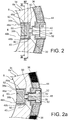
- the lateral body 8 has at its head end 8a a fluid communication system 30 specific to the invention, which will now be described with reference to figures 2 to 4 .
- the system 30 may constitute a drainage system, a vent system, or even a gas sampling system. It is associated with a sealing plug 32 helping to define the confinement enclosure 4 when it seals the system 30. This plug also forms a radiological shielding in order to limit radiological leaks in the area of the system 30.
- the system 30 When the plug 32 is removed, the system 30 is provided to cooperate with a shielded drainage or vent tool, which comprises a sealing system ensuring that the containment of the radioactive materials remains guaranteed during the operations carried out.
- the communication system 30 here passes through the head end 8a of the lateral body 8, which is generally formed by a metal ferrule 34 covered radially by a neutron protection layer 36.
- This system 30, which takes the general form of a network of channels, has two fluid inlet openings 38a, 38b at an interior surface 40 of the confinement enclosure 4. In addition, it comprises, at the level of a fluid outlet zone 42 of the exterior surface 44 of the lateral body, a single fluid outlet opening 39.
- the plug 32 associated with this system 30 covers this outlet region of fluid 42, as can be seen on the figure 2a . It is moreover the part of the outer surface 44 covered by the plug 32 which delimits said fluid outlet zone 42 within the meaning of the invention. Still in this mounted position, the plug 32 closes the fluid outlet opening 39, by covering it or also entering it.
- the fluid outlet zone 42 defines a housing 48 provided to house at least part of the sealing plug 32, when the latter occupies its mounted position.
- the plug 32 is thus at least partially integrated into the lateral body 8, as can be seen on the figure. figure 2a .
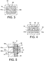
- the fluidic communication system 30 defines two distinct paths for the circulation of fluid 46a, 46b between the interior and the exterior of the confinement enclosure 4. More precisely, the first path 46a begins at the level of the first fluid inlet opening 38a from which extends a first elementary channel 48a comprising an elbow 50, for example at 90 °. Similarly, the second path 46b begins at the level of the second fluid inlet opening 38b from which extends a second elementary channel 48b comprising an elbow 50, also of the order of, for example, at 90 °.
- the two elementary channels 48a, 48b each have an upstream part and a downstream part separated by the elbow 50. The two upstream parts are substantially parallel, while the two downstream parts are of coincident axes and meet at the level. a junction with a main channel 52 defining a downstream part common to the two fluid circulation paths 46a, 46b.
- the main channel 52 is preferably straight, and has an axis parallel to the two axes of the upstream parts of the two elementary channels 48a, 48b.
- the axis of the main channel 52 is arranged between the two aforementioned axes, which are distributed symmetrically with respect to this axis of the main channel.
- the channels 48a, 48b, 52 preferably fit in the same plane 54 shown schematically on the figure 4 , corresponding to a transverse plane of the packaging, that is to say orthogonal to its axis 2. It is noted that in the case where the system 30 is implanted on the cover, the fictitious plane in which the channels is preferably a longitudinal plane of the packaging, passing through its axis 2.
- the single main channel 52 ends with the fluid outlet opening 39 opening into the housing 48 defined by the fluid outlet zone 42.
- the elementary channels 48a, 48b each have a section smaller than that of the main channel 52.
- the sum of the sections of the two elementary channels 48a, 48b is identical or similar to the higher section of the main channel 52.
- two elementary channels 48a, 48b are distinct from one another and respectively define two independent fluid circulation paths 46a, 46b.
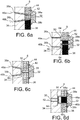
- the channels are straight and inclined with respect to each other, so as to form a V.
- Each elementary channel 48a, 48b therefore extends between the inlet opening 38a, 38b and the fluid outlet opening. 39a, 39b.
- each elementary channel 38a, 38b also incorporates a baffle 64.
- the design differs from that of the figure 5 by the simple fact that the upstream parts of the elementary channels 48a, 48b are no longer parallel, but inclined with respect to each other to form a V.
- the design is reversed from that of the figure 5 , by providing a main channel 52 extending from the inlet opening 38, as well as two elementary channels 48a, 48b respectively terminating in two outlet openings 39a, 39b.
- the two separate paths 46a, 46b are merged upstream in the main channel 52, before they separate, passing respectively through the two elementary channels 48a, 48b.
Landscapes
- Physics & Mathematics (AREA)
- Engineering & Computer Science (AREA)
- General Engineering & Computer Science (AREA)
- High Energy & Nuclear Physics (AREA)
- Packages (AREA)
- Packging For Living Organisms, Food Or Medicinal Products That Are Sensitive To Environmental Conditiond (AREA)
Claims (10)
- Verpackung (1) zum Transport und/oder zur Zwischenlagerung von radioaktiven Substanzen, welche mehrere Verpackungselemente (6, 8, 10) umfasst, die zusammen innen einen Sicherheitsbehälter (4) für die radioaktiven Substanzen (3) definieren, wobei wenigstens eines der Verpackungselemente von wenigstens einem Fluidverbindungssystem (30) durchquert wird, das an einer Innenfläche (40) des Behälters wenigstens eine Fluideintrittsöffnung (38, 38a, 38b) und an einem Fluidaustrittsbereich (42) der Außenfläche (44) des betreffenden Verpackungselements wenigstens eine Fluidaustrittsöffnung (39, 39a, 39b) aufweist, wobei das Fluidverbindungssystem mit einem Verschlussstopfen (32) verbunden ist, der den Fluidaustrittsbereich (42) so bedeckt, dass er die wenigstens eine Fluideintrittsöffnung verschließt,
dadurch gekennzeichnet, dass das Fluidverbindungssystem (30) wenigstens zwei verschiedene Fluidströmungswege (46a, 46b) zwischen der wenigstens einen Fluideintrittsöffnung (38, 38a, 38b) und der wenigstens einen Fluidaustrittsöffnung (39, 39a, 39b) definiert. - Verpackung nach Anspruch 1, dadurch gekennzeichnet, dass das Fluidverbindungssystem eine Anzahl N1 von Fluideintrittsöffnungen (38, 38a, 38b), die größer oder gleich eins ist, sowie eine Anzahl N2 von Fluidaustrittsöffnungen (39, 39a, 39b), die größer oder gleich eins ist, umfasst, wobei die Anzahl N1 größer als die, gleich der oder kleiner als die Anzahl N2 ist.
- Verpackung nach Anspruch 1 oder Anspruch 2,
dadurch gekennzeichnet, dass der Verschlussstopfen (32) wenigstens teilweise in einem Sitz (48) aufgenommen ist, der an dem zugeordneten Verpackungselement vorgesehen ist, wobei der Sitz durch den Fluidaustrittsbereich (42) der Außenfläche (44) dieses Verpackungselements definiert ist. - Verpackung nach einem der vorhergehenden Ansprüche, dadurch gekennzeichnet, dass die verschiedenen Fluidströmungswege (46a, 46b) aus mehreren Elementarkanälen (48a, 48b) gebildet werden, welche mit wenigstens einem Hauptkanal (52) in Verbindung stehen, der einen größeren Querschnitt aufweist und in einer Anzahl vorgesehen ist, die kleiner als diejenige der Elementarkanäle (48a, 48b) ist, wobei jeder Hauptkanal (52) einen Teil von mehreren der Fluidströmungswege (46a, 46b) definiert,
und dadurch, dass jeder Hauptkanal (52) am Fluidaustrittsbereich (42) mündet und die Elementarkanäle (46a, 46b) in den Sicherheitsbehälter (4) münden, oder umgekehrt. - Verpackung nach Anspruch 4, dadurch gekennzeichnet, dass sie zwei Elementarkanäle (48a, 48b), die in den Sicherheitsbehälter (4) münden, sowie einen einzigen Hauptkanal (52), der am Fluidaustrittsbereich (42) mündet, aufweist.
- Verpackung nach einem der Ansprüche 1 bis 3, dadurch gekennzeichnet, dass die verschiedenen Fluidströmungswege (46a, 46b) aus mehreren Elementarkanälen (48a, 48b) gebildet werden, welche jeweils einerseits in den Sicherheitsbehälter (4) und andererseits am Fluidaustrittsbereich (42) münden,
und dadurch, dass jeder Elementarkanal (48a, 48b) einen der Fluidströmungswege (46a, 46b) definiert. - Verpackung nach einem der Ansprüche 4 bis 6, dadurch gekennzeichnet, dass die Elementarkanäle und/oder der Hauptkanal/die Hauptkanäle gerade oder nicht gerade sind, wobei sie vorzugsweise wenigstens einen Bogen (50) und/oder eine Prallwand (64) aufweisen.
- Verpackung nach einem der Ansprüche 4 bis 7, dadurch gekennzeichnet, dass die Elementarkanäle und/oder der Hauptkanal/die Hauptkanäle in ein und derselben fiktiven Ebene (54) verlaufen.
- Verpackung nach einem der vorhergehenden Ansprüche, dadurch gekennzeichnet, dass alle verschiedenen Fluidströmungswege (46a, 46b) oder ein Teil davon innerhalb eines Einsatzes (60) hergestellt sind, der an das betreffende Verpackungselement angesetzt ist.
- Verpackung nach einem der vorhergehenden Ansprüche, dadurch gekennzeichnet, dass das Fluidverbindungssystem (30) ein Abflusssystem, ein Entlüftungssystem oder ein Gasentnahmesystem darstellt.
Applications Claiming Priority (2)
| Application Number | Priority Date | Filing Date | Title |
|---|---|---|---|
| FR1662237A FR3060192B1 (fr) | 2016-12-09 | 2016-12-09 | Emballage de transport et/ou d'entreposage de matieres radioactives comprenant un systeme de communication fluidique ameliore entre l'interieur et l'exterieur de l'enceinte de confinement |
| PCT/FR2017/053435 WO2018104670A1 (fr) | 2016-12-09 | 2017-12-07 | Emballage de transport et/ou d'entreposage de matières radioactives comprenant un système de communication fluidique amélioré entre l'intérieur et l'extérieur de l'enceinte de confinement |
Publications (2)
| Publication Number | Publication Date |
|---|---|
| EP3552215A1 EP3552215A1 (de) | 2019-10-16 |
| EP3552215B1 true EP3552215B1 (de) | 2020-11-18 |
Family
ID=58737627
Family Applications (1)
| Application Number | Title | Priority Date | Filing Date |
|---|---|---|---|
| EP17821974.7A Active EP3552215B1 (de) | 2016-12-09 | 2017-12-07 | Verpackung zum transport und/oder zur lagerung von radioaktiven substanzen mit einem verbesserten system zur fluidischen kommunikation zwischen dem inneren und dem äusseren des behälters |
Country Status (6)
| Country | Link |
|---|---|
| EP (1) | EP3552215B1 (de) |
| JP (1) | JP7018445B2 (de) |
| CN (1) | CN110050309B (de) |
| ES (1) | ES2853982T3 (de) |
| FR (1) | FR3060192B1 (de) |
| WO (1) | WO2018104670A1 (de) |
Families Citing this family (2)
| Publication number | Priority date | Publication date | Assignee | Title |
|---|---|---|---|---|
| RU2735799C1 (ru) * | 2020-02-25 | 2020-11-09 | Федеральное государственное унитарное предприятие "Российский Федеральный ядерный центр - Всероссийский научно-исследовательский институт экспериментальной физики" (ФГУП "РФЯЦ-ВНИИЭФ") | Способ загрузки пенала с радионуклидом высокой активности в защитный контейнер и устройство для его осуществления |
| FR3114907B1 (fr) | 2020-10-07 | 2022-12-23 | Tn Int | Emballage pour le transport et/ou le stockage de matieres radioactives, comprenant un dispositif de protection radiologique reduisant les risques de fuites radiologiques |
Family Cites Families (13)
| Publication number | Priority date | Publication date | Assignee | Title |
|---|---|---|---|---|
| FR2419568A1 (fr) * | 1978-03-09 | 1979-10-05 | Commissariat Energie Atomique | Dispositif de jonction entre un conteneur et une enceinte de dechargement |
| JPH01131200U (de) * | 1988-03-01 | 1989-09-06 | ||
| FR2762132B1 (fr) * | 1997-04-10 | 1999-06-18 | Commissariat Energie Atomique | Emballage de transport de colis dangereux, tels que des colis nucleaires de forte activite |
| SE521224C2 (sv) * | 2001-01-29 | 2003-10-14 | Hans Georgii | Anordning för förvaring av värmeproducerande riskmaterial, i synnerhet kärnbränsle, och för en sådan anordning avsett kärl |
| US7707741B2 (en) * | 2005-06-06 | 2010-05-04 | Holtec International, Inc. | Method and apparatus for dehydrating high level waste based on dew point temperature measurements |
| CN103531259A (zh) * | 2007-10-29 | 2014-01-22 | 霍尔泰克国际股份有限公司 | 用于支持放射性燃料组件的设备 |
| FR2961005B1 (fr) * | 2010-06-02 | 2015-12-11 | Tn Int | Emballage pour le transport et/ou entreposage de matieres radioactives, comprenant des moyens de conduction thermique ameliores |
| FR2985365B1 (fr) * | 2011-12-29 | 2014-01-24 | Tn Int | Conducteur thermique pour corps lateral d'emballage de transport et/ou d'entreposage de matieres radioactives |
| FR2996346B1 (fr) * | 2012-10-02 | 2014-10-31 | Tn Int | Emballage pour le transport et/ou l'entreposage de matieres radioactives, comprenant des moyens ameliores de fixation d'un capot amortisseur de chocs |
| US9466400B2 (en) * | 2013-01-25 | 2016-10-11 | Holtec International | Ventilated transfer cask with lifting feature |
| US20140270042A1 (en) * | 2013-03-13 | 2014-09-18 | Westinghouse Electric Company Llc | Source of electricity derived from a spent fuel cask |
| CA2906234C (en) * | 2013-03-14 | 2021-06-15 | Atomic Energy Of Canada Limited / Energie Atomique Du Canada Limitee | Sealing apparatus for mitigating emissions of hazardous gases |
| FR3006098B1 (fr) * | 2013-05-22 | 2015-06-26 | Tn Int | Emballage d'entreposage de combustible irradie comprenant des rails amortis de guidage d'etui |
-
2016
- 2016-12-09 FR FR1662237A patent/FR3060192B1/fr not_active Expired - Fee Related
-
2017
- 2017-12-07 JP JP2019530124A patent/JP7018445B2/ja active Active
- 2017-12-07 WO PCT/FR2017/053435 patent/WO2018104670A1/fr not_active Ceased
- 2017-12-07 CN CN201780075739.0A patent/CN110050309B/zh active Active
- 2017-12-07 EP EP17821974.7A patent/EP3552215B1/de active Active
- 2017-12-07 ES ES17821974T patent/ES2853982T3/es active Active
Non-Patent Citations (1)
| Title |
|---|
| None * |
Also Published As
| Publication number | Publication date |
|---|---|
| FR3060192B1 (fr) | 2019-05-17 |
| WO2018104670A1 (fr) | 2018-06-14 |
| EP3552215A1 (de) | 2019-10-16 |
| ES2853982T3 (es) | 2021-09-20 |
| CN110050309B (zh) | 2023-02-17 |
| JP2020501150A (ja) | 2020-01-16 |
| JP7018445B2 (ja) | 2022-02-10 |
| FR3060192A1 (fr) | 2018-06-15 |
| CN110050309A (zh) | 2019-07-23 |
Similar Documents
| Publication | Publication Date | Title |
|---|---|---|
| EP2140459B1 (de) | Container zum transportieren und/oder lagern von kernmaterialien mit einer aus auf eine metallverstärkung gegossenem blei hergestellten radiologischen abschirmung | |
| EP3552215B1 (de) | Verpackung zum transport und/oder zur lagerung von radioaktiven substanzen mit einem verbesserten system zur fluidischen kommunikation zwischen dem inneren und dem äusseren des behälters | |
| EP1166279A1 (de) | Anlage zur langzeitlagerung von wärmeentwickelnden materialien wie zum beispiel nukleare abfallstoffe | |
| EP1428453A1 (de) | Puderdose für kosmetische Zwecke | |
| FR2987607A1 (fr) | Bouchon pour un col de recipient | |
| EP2320429B1 (de) | Verpackung für den Transport und/oder zur Zwischenlagerung radioaktiver Stoffe, die radial geschichtete Strahlenschutzelemente umfasst | |
| WO2012028365A1 (fr) | Protecteur de tube d'extraction de pétrole | |
| EP3042378A1 (de) | Verpackung mit verbesserten mitteln zur stossdämpfung zwischen einer anordnung mit radioaktiven materialien und deckel für diese verpackung | |
| FR3046117B1 (fr) | Reservoir de vehicule comprenant une membrane semi-permeable. | |
| FR1464973A (fr) | Robinet-vanne du type sans conduit | |
| EP3766082B1 (de) | Verpackung zum transport und/oder lagern von radioaktiven materialien, die eine einfachere herstellung und verbesserte wärmeleitfähigkeit ermöglicht | |
| BE1009922A7 (fr) | Bouchon de fermeture d'un orifice realise dans une enveloppe de protection. | |
| EP3782168B1 (de) | Behälter für den transport und/oder die lagerung von radioaktivem material mit vorrichtung zum erleichtern der handhabung des radioaktiven materiales | |
| FR2578951A1 (fr) | Raccord multiple pour canalisations de fluides | |
| EP2237385B1 (de) | Kabeldurchführungsgarnitur | |
| EP4315369B1 (de) | Vorrichtung zum transport von uranhexafluorid mit stossdämpfern | |
| EP4126692B1 (de) | Verschluss geeignet um eine flüssigkeit zu enthalten | |
| EP0509926B1 (de) | Einrichtung zur biologischen Abschirmung eines Kreislaufelements für radioaktive Flüssigkeit | |
| FR2537637A1 (fr) | Pierre de manteau de cheminee destinee a une cheminee multicorps et procede pour y pratiquer une ouverture de reception d'un encadrement de porte ou d'un raccord pour tuyau | |
| WO2022038325A1 (fr) | Ensemble pour le transport d'hexafluorure d'uranium | |
| FR3116294A1 (fr) | Système de poteau muni d’un fourreau de protection | |
| EP2805332B1 (de) | Sicherheitsventil und strahlungsschutzvorrichtung | |
| WO2020212285A1 (fr) | Bouchon flotteur muni de pièges d'air | |
| FR3134222A1 (fr) | Colis comprenant un emballage pour le transport et/ou l’entreposage d’un contenu radioactif, et comportant un systeme amortisseur interne a encombrement reduit | |
| FR3076057A1 (fr) | Emballage de transport et/ou d'entreposage de matieres radioactives presentant des moyens ameliores de maintien de capot amortisseur |
Legal Events
| Date | Code | Title | Description |
|---|---|---|---|
| STAA | Information on the status of an ep patent application or granted ep patent |
Free format text: STATUS: UNKNOWN |
|
| STAA | Information on the status of an ep patent application or granted ep patent |
Free format text: STATUS: THE INTERNATIONAL PUBLICATION HAS BEEN MADE |
|
| PUAI | Public reference made under article 153(3) epc to a published international application that has entered the european phase |
Free format text: ORIGINAL CODE: 0009012 |
|
| STAA | Information on the status of an ep patent application or granted ep patent |
Free format text: STATUS: REQUEST FOR EXAMINATION WAS MADE |
|
| 17P | Request for examination filed |
Effective date: 20190612 |
|
| AK | Designated contracting states |
Kind code of ref document: A1 Designated state(s): AL AT BE BG CH CY CZ DE DK EE ES FI FR GB GR HR HU IE IS IT LI LT LU LV MC MK MT NL NO PL PT RO RS SE SI SK SM TR |
|
| AX | Request for extension of the european patent |
Extension state: BA ME |
|
| DAV | Request for validation of the european patent (deleted) | ||
| DAX | Request for extension of the european patent (deleted) | ||
| GRAP | Despatch of communication of intention to grant a patent |
Free format text: ORIGINAL CODE: EPIDOSNIGR1 |
|
| STAA | Information on the status of an ep patent application or granted ep patent |
Free format text: STATUS: GRANT OF PATENT IS INTENDED |
|
| INTG | Intention to grant announced |
Effective date: 20200610 |
|
| GRAS | Grant fee paid |
Free format text: ORIGINAL CODE: EPIDOSNIGR3 |
|
| GRAA | (expected) grant |
Free format text: ORIGINAL CODE: 0009210 |
|
| STAA | Information on the status of an ep patent application or granted ep patent |
Free format text: STATUS: THE PATENT HAS BEEN GRANTED |
|
| AK | Designated contracting states |
Kind code of ref document: B1 Designated state(s): AL AT BE BG CH CY CZ DE DK EE ES FI FR GB GR HR HU IE IS IT LI LT LU LV MC MK MT NL NO PL PT RO RS SE SI SK SM TR |
|
| REG | Reference to a national code |
Ref country code: GB Ref legal event code: FG4D Free format text: NOT ENGLISH |
|
| REG | Reference to a national code |
Ref country code: CH Ref legal event code: EP |
|
| REG | Reference to a national code |
Ref country code: IE Ref legal event code: FG4D Free format text: LANGUAGE OF EP DOCUMENT: FRENCH |
|
| REG | Reference to a national code |
Ref country code: DE Ref legal event code: R096 Ref document number: 602017027959 Country of ref document: DE |
|
| REG | Reference to a national code |
Ref country code: AT Ref legal event code: REF Ref document number: 1336653 Country of ref document: AT Kind code of ref document: T Effective date: 20201215 |
|
| REG | Reference to a national code |
Ref country code: CH Ref legal event code: NV Representative=s name: BOVARD AG PATENT- UND MARKENANWAELTE, CH |
|
| REG | Reference to a national code |
Ref country code: AT Ref legal event code: MK05 Ref document number: 1336653 Country of ref document: AT Kind code of ref document: T Effective date: 20201118 |
|
| REG | Reference to a national code |
Ref country code: NL Ref legal event code: MP Effective date: 20201118 |
|
| PG25 | Lapsed in a contracting state [announced via postgrant information from national office to epo] |
Ref country code: NO Free format text: LAPSE BECAUSE OF FAILURE TO SUBMIT A TRANSLATION OF THE DESCRIPTION OR TO PAY THE FEE WITHIN THE PRESCRIBED TIME-LIMIT Effective date: 20210218 Ref country code: GR Free format text: LAPSE BECAUSE OF FAILURE TO SUBMIT A TRANSLATION OF THE DESCRIPTION OR TO PAY THE FEE WITHIN THE PRESCRIBED TIME-LIMIT Effective date: 20210219 Ref country code: RS Free format text: LAPSE BECAUSE OF FAILURE TO SUBMIT A TRANSLATION OF THE DESCRIPTION OR TO PAY THE FEE WITHIN THE PRESCRIBED TIME-LIMIT Effective date: 20201118 Ref country code: PT Free format text: LAPSE BECAUSE OF FAILURE TO SUBMIT A TRANSLATION OF THE DESCRIPTION OR TO PAY THE FEE WITHIN THE PRESCRIBED TIME-LIMIT Effective date: 20210318 Ref country code: FI Free format text: LAPSE BECAUSE OF FAILURE TO SUBMIT A TRANSLATION OF THE DESCRIPTION OR TO PAY THE FEE WITHIN THE PRESCRIBED TIME-LIMIT Effective date: 20201118 |
|
| PG25 | Lapsed in a contracting state [announced via postgrant information from national office to epo] |
Ref country code: BG Free format text: LAPSE BECAUSE OF FAILURE TO SUBMIT A TRANSLATION OF THE DESCRIPTION OR TO PAY THE FEE WITHIN THE PRESCRIBED TIME-LIMIT Effective date: 20210218 Ref country code: SE Free format text: LAPSE BECAUSE OF FAILURE TO SUBMIT A TRANSLATION OF THE DESCRIPTION OR TO PAY THE FEE WITHIN THE PRESCRIBED TIME-LIMIT Effective date: 20201118 Ref country code: IS Free format text: LAPSE BECAUSE OF FAILURE TO SUBMIT A TRANSLATION OF THE DESCRIPTION OR TO PAY THE FEE WITHIN THE PRESCRIBED TIME-LIMIT Effective date: 20210318 Ref country code: LV Free format text: LAPSE BECAUSE OF FAILURE TO SUBMIT A TRANSLATION OF THE DESCRIPTION OR TO PAY THE FEE WITHIN THE PRESCRIBED TIME-LIMIT Effective date: 20201118 Ref country code: PL Free format text: LAPSE BECAUSE OF FAILURE TO SUBMIT A TRANSLATION OF THE DESCRIPTION OR TO PAY THE FEE WITHIN THE PRESCRIBED TIME-LIMIT Effective date: 20201118 Ref country code: AT Free format text: LAPSE BECAUSE OF FAILURE TO SUBMIT A TRANSLATION OF THE DESCRIPTION OR TO PAY THE FEE WITHIN THE PRESCRIBED TIME-LIMIT Effective date: 20201118 |
|
| REG | Reference to a national code |
Ref country code: LT Ref legal event code: MG9D |
|
| PG25 | Lapsed in a contracting state [announced via postgrant information from national office to epo] |
Ref country code: HR Free format text: LAPSE BECAUSE OF FAILURE TO SUBMIT A TRANSLATION OF THE DESCRIPTION OR TO PAY THE FEE WITHIN THE PRESCRIBED TIME-LIMIT Effective date: 20201118 |
|
| PG25 | Lapsed in a contracting state [announced via postgrant information from national office to epo] |
Ref country code: SK Free format text: LAPSE BECAUSE OF FAILURE TO SUBMIT A TRANSLATION OF THE DESCRIPTION OR TO PAY THE FEE WITHIN THE PRESCRIBED TIME-LIMIT Effective date: 20201118 Ref country code: RO Free format text: LAPSE BECAUSE OF FAILURE TO SUBMIT A TRANSLATION OF THE DESCRIPTION OR TO PAY THE FEE WITHIN THE PRESCRIBED TIME-LIMIT Effective date: 20201118 Ref country code: SM Free format text: LAPSE BECAUSE OF FAILURE TO SUBMIT A TRANSLATION OF THE DESCRIPTION OR TO PAY THE FEE WITHIN THE PRESCRIBED TIME-LIMIT Effective date: 20201118 Ref country code: EE Free format text: LAPSE BECAUSE OF FAILURE TO SUBMIT A TRANSLATION OF THE DESCRIPTION OR TO PAY THE FEE WITHIN THE PRESCRIBED TIME-LIMIT Effective date: 20201118 Ref country code: CZ Free format text: LAPSE BECAUSE OF FAILURE TO SUBMIT A TRANSLATION OF THE DESCRIPTION OR TO PAY THE FEE WITHIN THE PRESCRIBED TIME-LIMIT Effective date: 20201118 Ref country code: LT Free format text: LAPSE BECAUSE OF FAILURE TO SUBMIT A TRANSLATION OF THE DESCRIPTION OR TO PAY THE FEE WITHIN THE PRESCRIBED TIME-LIMIT Effective date: 20201118 |
|
| REG | Reference to a national code |
Ref country code: DE Ref legal event code: R097 Ref document number: 602017027959 Country of ref document: DE |
|
| PG25 | Lapsed in a contracting state [announced via postgrant information from national office to epo] |
Ref country code: DK Free format text: LAPSE BECAUSE OF FAILURE TO SUBMIT A TRANSLATION OF THE DESCRIPTION OR TO PAY THE FEE WITHIN THE PRESCRIBED TIME-LIMIT Effective date: 20201118 Ref country code: MC Free format text: LAPSE BECAUSE OF FAILURE TO SUBMIT A TRANSLATION OF THE DESCRIPTION OR TO PAY THE FEE WITHIN THE PRESCRIBED TIME-LIMIT Effective date: 20201118 |
|
| REG | Reference to a national code |
Ref country code: ES Ref legal event code: FG2A Ref document number: 2853982 Country of ref document: ES Kind code of ref document: T3 Effective date: 20210920 |
|
| PLBE | No opposition filed within time limit |
Free format text: ORIGINAL CODE: 0009261 |
|
| STAA | Information on the status of an ep patent application or granted ep patent |
Free format text: STATUS: NO OPPOSITION FILED WITHIN TIME LIMIT |
|
| 26N | No opposition filed |
Effective date: 20210819 |
|
| PG25 | Lapsed in a contracting state [announced via postgrant information from national office to epo] |
Ref country code: NL Free format text: LAPSE BECAUSE OF FAILURE TO SUBMIT A TRANSLATION OF THE DESCRIPTION OR TO PAY THE FEE WITHIN THE PRESCRIBED TIME-LIMIT Effective date: 20201118 Ref country code: AL Free format text: LAPSE BECAUSE OF FAILURE TO SUBMIT A TRANSLATION OF THE DESCRIPTION OR TO PAY THE FEE WITHIN THE PRESCRIBED TIME-LIMIT Effective date: 20201118 Ref country code: IE Free format text: LAPSE BECAUSE OF NON-PAYMENT OF DUE FEES Effective date: 20201207 Ref country code: LU Free format text: LAPSE BECAUSE OF NON-PAYMENT OF DUE FEES Effective date: 20201207 Ref country code: IT Free format text: LAPSE BECAUSE OF FAILURE TO SUBMIT A TRANSLATION OF THE DESCRIPTION OR TO PAY THE FEE WITHIN THE PRESCRIBED TIME-LIMIT Effective date: 20201118 |
|
| PG25 | Lapsed in a contracting state [announced via postgrant information from national office to epo] |
Ref country code: SI Free format text: LAPSE BECAUSE OF FAILURE TO SUBMIT A TRANSLATION OF THE DESCRIPTION OR TO PAY THE FEE WITHIN THE PRESCRIBED TIME-LIMIT Effective date: 20201118 |
|
| PG25 | Lapsed in a contracting state [announced via postgrant information from national office to epo] |
Ref country code: IS Free format text: LAPSE BECAUSE OF FAILURE TO SUBMIT A TRANSLATION OF THE DESCRIPTION OR TO PAY THE FEE WITHIN THE PRESCRIBED TIME-LIMIT Effective date: 20210318 Ref country code: TR Free format text: LAPSE BECAUSE OF FAILURE TO SUBMIT A TRANSLATION OF THE DESCRIPTION OR TO PAY THE FEE WITHIN THE PRESCRIBED TIME-LIMIT Effective date: 20201118 Ref country code: MT Free format text: LAPSE BECAUSE OF FAILURE TO SUBMIT A TRANSLATION OF THE DESCRIPTION OR TO PAY THE FEE WITHIN THE PRESCRIBED TIME-LIMIT Effective date: 20201118 Ref country code: CY Free format text: LAPSE BECAUSE OF FAILURE TO SUBMIT A TRANSLATION OF THE DESCRIPTION OR TO PAY THE FEE WITHIN THE PRESCRIBED TIME-LIMIT Effective date: 20201118 |
|
| PG25 | Lapsed in a contracting state [announced via postgrant information from national office to epo] |
Ref country code: MK Free format text: LAPSE BECAUSE OF FAILURE TO SUBMIT A TRANSLATION OF THE DESCRIPTION OR TO PAY THE FEE WITHIN THE PRESCRIBED TIME-LIMIT Effective date: 20201118 |
|
| P01 | Opt-out of the competence of the unified patent court (upc) registered |
Effective date: 20230526 |
|
| PGFP | Annual fee paid to national office [announced via postgrant information from national office to epo] |
Ref country code: CH Payment date: 20250109 Year of fee payment: 8 |
|
| REG | Reference to a national code |
Ref country code: CH Ref legal event code: U11 Free format text: ST27 STATUS EVENT CODE: U-0-0-U10-U11 (AS PROVIDED BY THE NATIONAL OFFICE) Effective date: 20260108 |
|
| PGFP | Annual fee paid to national office [announced via postgrant information from national office to epo] |
Ref country code: GB Payment date: 20251224 Year of fee payment: 9 |
|
| PGFP | Annual fee paid to national office [announced via postgrant information from national office to epo] |
Ref country code: FR Payment date: 20251223 Year of fee payment: 9 |
|
| PGFP | Annual fee paid to national office [announced via postgrant information from national office to epo] |
Ref country code: ES Payment date: 20260108 Year of fee payment: 9 |
|
| PGFP | Annual fee paid to national office [announced via postgrant information from national office to epo] |
Ref country code: DE Payment date: 20251229 Year of fee payment: 9 |
|
| PGFP | Annual fee paid to national office [announced via postgrant information from national office to epo] |
Ref country code: BE Payment date: 20251226 Year of fee payment: 9 |