EP3552011B1 - Unité d'analyse - Google Patents
Unité d'analyse Download PDFInfo
- Publication number
- EP3552011B1 EP3552011B1 EP17801701.8A EP17801701A EP3552011B1 EP 3552011 B1 EP3552011 B1 EP 3552011B1 EP 17801701 A EP17801701 A EP 17801701A EP 3552011 B1 EP3552011 B1 EP 3552011B1
- Authority
- EP
- European Patent Office
- Prior art keywords
- housing part
- connection
- plane
- analysis unit
- channel
- Prior art date
- Legal status (The legal status is an assumption and is not a legal conclusion. Google has not performed a legal analysis and makes no representation as to the accuracy of the status listed.)
- Active
Links
- VNWKTOKETHGBQD-UHFFFAOYSA-N methane Chemical compound C VNWKTOKETHGBQD-UHFFFAOYSA-N 0.000 claims description 21
- 239000000463 material Substances 0.000 claims description 16
- 229930195733 hydrocarbon Natural products 0.000 claims description 13
- 150000002430 hydrocarbons Chemical class 0.000 claims description 12
- 238000005259 measurement Methods 0.000 claims description 8
- 238000010438 heat treatment Methods 0.000 claims description 4
- 239000004215 Carbon black (E152) Substances 0.000 claims description 2
- 239000012530 fluid Substances 0.000 claims 4
- 239000007789 gas Substances 0.000 description 27
- 238000009434 installation Methods 0.000 description 12
- 238000006243 chemical reaction Methods 0.000 description 8
- CURLTUGMZLYLDI-UHFFFAOYSA-N Carbon dioxide Chemical compound O=C=O CURLTUGMZLYLDI-UHFFFAOYSA-N 0.000 description 4
- 238000012423 maintenance Methods 0.000 description 4
- 238000004519 manufacturing process Methods 0.000 description 4
- 239000001257 hydrogen Substances 0.000 description 3
- 229910052739 hydrogen Inorganic materials 0.000 description 3
- 230000002093 peripheral effect Effects 0.000 description 3
- UFHFLCQGNIYNRP-UHFFFAOYSA-N Hydrogen Chemical compound [H][H] UFHFLCQGNIYNRP-UHFFFAOYSA-N 0.000 description 2
- QVGXLLKOCUKJST-UHFFFAOYSA-N atomic oxygen Chemical compound [O] QVGXLLKOCUKJST-UHFFFAOYSA-N 0.000 description 2
- 239000001569 carbon dioxide Substances 0.000 description 2
- 229910002092 carbon dioxide Inorganic materials 0.000 description 2
- 238000011156 evaluation Methods 0.000 description 2
- AMWRITDGCCNYAT-UHFFFAOYSA-L hydroxy(oxo)manganese;manganese Chemical compound [Mn].O[Mn]=O.O[Mn]=O AMWRITDGCCNYAT-UHFFFAOYSA-L 0.000 description 2
- VUZPPFZMUPKLLV-UHFFFAOYSA-N methane;hydrate Chemical compound C.O VUZPPFZMUPKLLV-UHFFFAOYSA-N 0.000 description 2
- 238000000034 method Methods 0.000 description 2
- 239000001301 oxygen Substances 0.000 description 2
- 229910052760 oxygen Inorganic materials 0.000 description 2
- XLYOFNOQVPJJNP-UHFFFAOYSA-N water Substances O XLYOFNOQVPJJNP-UHFFFAOYSA-N 0.000 description 2
- QPLDLSVMHZLSFG-UHFFFAOYSA-N Copper oxide Chemical compound [Cu]=O QPLDLSVMHZLSFG-UHFFFAOYSA-N 0.000 description 1
- 239000005751 Copper oxide Substances 0.000 description 1
- 230000004323 axial length Effects 0.000 description 1
- 239000012159 carrier gas Substances 0.000 description 1
- 239000003054 catalyst Substances 0.000 description 1
- 230000003197 catalytic effect Effects 0.000 description 1
- 239000004568 cement Substances 0.000 description 1
- 229910000431 copper oxide Inorganic materials 0.000 description 1
- 238000013461 design Methods 0.000 description 1
- 150000002431 hydrogen Chemical class 0.000 description 1
- 238000003780 insertion Methods 0.000 description 1
- 230000037431 insertion Effects 0.000 description 1
- 230000007257 malfunction Effects 0.000 description 1
- -1 methane hydrocarbons Chemical class 0.000 description 1
- 238000003801 milling Methods 0.000 description 1
- 239000000203 mixture Substances 0.000 description 1
- 238000012544 monitoring process Methods 0.000 description 1
- 238000005192 partition Methods 0.000 description 1
- 230000000717 retained effect Effects 0.000 description 1
Images
Classifications
-
- G—PHYSICS
- G01—MEASURING; TESTING
- G01N—INVESTIGATING OR ANALYSING MATERIALS BY DETERMINING THEIR CHEMICAL OR PHYSICAL PROPERTIES
- G01N33/00—Investigating or analysing materials by specific methods not covered by groups G01N1/00 - G01N31/00
- G01N33/0004—Gaseous mixtures, e.g. polluted air
- G01N33/0009—General constructional details of gas analysers, e.g. portable test equipment
- G01N33/0011—Sample conditioning
-
- G—PHYSICS
- G01—MEASURING; TESTING
- G01N—INVESTIGATING OR ANALYSING MATERIALS BY DETERMINING THEIR CHEMICAL OR PHYSICAL PROPERTIES
- G01N27/00—Investigating or analysing materials by the use of electric, electrochemical, or magnetic means
- G01N27/62—Investigating or analysing materials by the use of electric, electrochemical, or magnetic means by investigating the ionisation of gases, e.g. aerosols; by investigating electric discharges, e.g. emission of cathode
Definitions
- the invention relates to an analysis unit with a frontal plane from which the analysis unit is accessible and parallel fastening planes which are arranged perpendicular to the frontal plane and a gas measuring device.
- Such analysis units are usually arranged in control cabinets which have a door on their front side, via which the fitter or the operating personnel have access to the individual measuring devices and their peripheral elements, so that they are attached as accessible from the front side as possible.
- the measuring devices and peripheral elements are mostly composed of several housing parts, of which at least one is attached, for example, to one of the cabinet floors, which then serves as a mounting plane, while the other housing parts have to be mounted on this part.
- access to individual devices may only be possible to a limited extent, so that assembly and disassembly are difficult, especially when using tools.
- a flame ionization detector such as that shown in FIG DE 196 21 293 A1 is described, in addition to the room in which the flame or flames are generated and the gas and power lines leading there to supply the electrodes and the elements for determining the electrons released during the ionization and the connected electronic evaluation unit on a converter in which Hydrocarbon molecules with the exception of methane with hydrogen molecules and oxygen molecules on one Catalyst surface can be converted into carbon dioxide and water.
- one flame of the flame ionization detector is flowed through by the exhaust gas flow, while the other flame is flowed through by the exhaust gas flow passed through the converter, so that only the methane content in the exhaust gas is determined at the other flame, whereby the conversion rate of the converter must be observed, which are about 13% in terms of methane.
- the amount of hydrocarbons without the methane content can then be determined by calculating the difference.
- the DE 20 2009 014 666 U1 discloses a switch cabinet for exhaust gas measurement, in which an analysis unit and a gas measuring device are arranged accordingly.
- the task is therefore to design an analysis unit in such a way that the measuring devices and / or their peripheral devices can be easily installed and removed by improving the accessibility of these devices and at the same time making it possible to adapt the installation direction to the existing installation space without to have to change the housing parts for this.
- the gas measuring device has at least one connection housing part through which an inlet channel extends from the fastening plane to a connection plane and an outlet channel extends from the connection plane to the fastening plane, and has a base housing part with a connection plane which corresponds to the connection plane of the connection housing part and on which the The base housing part rests against the connection housing part, with an inflow channel being formed in the base housing part, which is fluidically connected to the inlet channel of the connection housing part via the connection plane and a return flow channel is formed which is fluidically connected to the outlet channel of the connection housing part via the connection plane, the corresponding connection planes in 45 ° angle are arranged tilted from the fastening plane in the direction of the frontal plane, a flange via which the two housing parts are connected to one another remains easily accessible from the front.
- the base housing can be attached to the connection housing part in two directions and secured by rotating the base housing part around its own axis and tilting it by 90 °. So two at a 90 ° angle mutually related directions of extension of the basic housing part are produced during assembly, which enables attachment depending on the available installation space.
- connection housing part and in the base housing part are arranged symmetrically to a plane of symmetry which runs perpendicular to the plane of attachment. In this way, correct gas guidance is ensured for both alternative installation directions without having to adapt the components to be fastened to one another.
- the basic housing part has a flange plate whose first flange surface forms the connection plane and whose second flange surface runs parallel to the connection plane, with bores extending through the flange plate from the first flange surface to the second flange surface.
- connection housing part in which screws can be rotated, which extend through the bores of the flange plate into the threaded bores.
- a body of the basic housing part extends between the two bores at a 45 ° angle to the flange surfaces, the basic housing part being attachable to the connection housing part in two positions arranged perpendicular to one another.
- the basic housing part extends either perpendicular to the cabinet Fastening level or to the cabinet floor or to the front.
- assembly can be carried out in this way with identical parts, whereby production costs can be reduced.
- the inclined connection plane of the connection housing part merges into a support surface which is arranged parallel to the fastening plane.
- the inclined connection plane of the basic housing part merges into a surface which is angled by 45 ° to the connection plane and which can be placed on the support surface of the connection housing part in a first fastening position. This facilitates the assembly process, since the basic housing part can be placed on the connection housing part during assembly without having to be held. Nevertheless, the inclined connection level remains to improve accessibility.
- converter material which is used to convert hydrocarbons into methane, is arranged in the inflow channel and / or in the return flow channel of the basic housing part.
- the basic housing part serves as the housing of a converter, which can be installed in a correspondingly simple manner and whose accessibility is retained, for example for exchanging the converter material, without having to remove the entire flame ionization detector for this purpose.
- This minimization in particular the overall axial length of a converter, can be shortened even further by forming two further parallel flow ducts in the basic housing part between the inflow duct and the return flow duct, in which converter material is arranged and which are connected to the adjacent one Inflow channel or return flow channel are connected to one another via axial recesses between the ends of the inflow channel pointing away from the connection housing part and the adjacent throughflow channel and the return flow channel and the adjacent throughflow channel.
- a complete flow of converter material through all four gas channels is ensured by a connecting channel between the two flow channels being formed in the base housing part at the end facing the connection housing part, so that the base housing part flows through in a meandering manner. Accordingly, the flow through the converter channels one after the other without leaving the basic housing part.
- a first circular recess is preferably formed on the connection plane of the connection housing part, into which the inlet channel opens and which is fluidically connected to the inflow channel of the base housing part, and a second circular recess is formed into which the return flow channel of the main housing part opens and which fluidly connects to the outlet channel of the connection housing part is connected, and formed a slot-shaped recess into which the two flow channels of the base housing part open.
- the inflow channel, the return flow channel and the two throughflow channels are closed by means of a plate screwed onto their end opposite to the connection housing part.
- At least one first receiving opening, in which a heating cartridge is arranged, and at least one second receiving opening, in which a temperature sensor is arranged can advantageously be formed in the basic housing part.
- a preferred temperature of around 280 ° C. can be generated and checked in the converter in order to ensure an optimal conversion of the hydrocarbons.
- the gas measuring device is preferably a flame ionization detector and the basic housing part correspondingly forms a converter.
- This gas measuring device is usually made up of different housing parts, the accessibility of which must be ensured as individually as possible in order to be able to carry out maintenance.
- An analysis unit is thus created which, due to its significantly improved accessibility, is very easy to maintain and install.
- production advantages are achieved, since optimal mounting directions can be achieved with identical parts even with different installation spaces available.
- Particular advantages are achieved in particular in the manufacture, assembly and maintenance of a converter of a flame ionization detector.
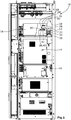
- the Figure 1 shows a section of a control cabinet with an analysis unit according to the invention.
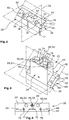
- the Figure 2 shows a connection housing part of the analysis unit according to the invention in a perspective view Figure 1 .
- the Figure 3 shows a perspective representation of a basic housing part of the analysis unit according to the invention Figure 1 .
- the Figure 4 shows a plan view of the basic housing part of the analysis unit according to the invention Figure 1 from underneath.
- the analysis unit shown is arranged in a switch cabinet 10 which contains various gas measuring devices 12, 14, 16.
- the upper of these gas measuring devices 12 is a flame ionization detector, in the outer housing 18 of which several further housing parts 20, 22, 24 to be mounted are arranged.
- a plurality of assembled housing parts 20 surround the space in which two flames of the flame ionization detector 12 are formed, the necessary gas supply lines and discharges and the necessary electronics for measurement and evaluation on the detector.
- a proportion of methane and a proportion of the total hydrocarbons present are determined in a known manner by conveying the measurement gas to the flame with a carrier gas stream containing hydrogen, among other things, where thermal ionization takes place, through which a measurable conductivity between two electrodes takes place is generated, which is a measure of the hydrocarbons present in the measuring gas.
- the measurement gas flow is divided into a first partial flow, which is conveyed directly to the first flame, so that a total flow of all hydrocarbons present can be determined there, and a second partial flow, which is fed to a second flame via a converter 26.
- a converter material which can be, for example, hopcalite, which is a mixture of copper oxide and manganese oxide, in the presence of hydrogen and oxygen to form carbon dioxide and water converted. While the remaining hydrocarbons are almost completely converted, only about 13% of the methane is converted in this converter 26, so that by appropriate conversion of the conductivity of the gas determined in the second flame, the proportion of methane in the total hydrocarbons present can be determined .
- this converter 26 contains the converter material which is to be introduced into correspondingly shaped channels of the converter 26.
- this material may have to be replaced during maintenance of the measuring devices, so that good accessibility is desired.
- connection housing 22 in which an inlet channel 34 and an outlet channel 36 are formed, into each of which one of the gas lines 30, 32 open.
- This connection housing 22 is fastened to a mounting plate 40 serving as a fastening plane 38 by means of screws 41, which extends perpendicular to a rear wall 42 of the switch cabinet 10 and is accordingly arranged perpendicular to the accessible front 28 of the switch cabinet 10.
- connection housing part 22 shown has a connection plane 44 which is tilted by 45 ° in the direction of the front side 28 in relation to the fastening plane 38 and which, in the area facing the rear wall 42, merges into a support surface 46 which extends parallel to the fastening plane 38.
- connection plane 44 of the connection housing part 22 two threaded bores 48 are formed in the outer area as well as a first circular recess 50 into which the inlet channel 34 opens, and a second circular recess 52 from which the outlet channel 36 extends through the connection housing part 22 and a slot-shaped recess 54 arranged therebetween is formed.
- connection housing part 22 and the channels 34, 36, bores 48 and recesses 50, 52, 54 formed therein are each arranged symmetrically to a plane of symmetry 56 which runs perpendicular to the fastening plane 38 and to the connection plane 44 and the connection housing part 22 is centrally divided into two equal sections Splits.
- connection housing part 22 On this connection housing part 22, a base housing part 24 of the converter 26 is mounted, which in the Figures 3 and 4 is shown.
- This has a flange plate 58, the flange surface 60 of which facing the connection housing part 22 has a connection plane after assembly which corresponds to the connection plane 44 of the connection housing part 22.
- This flange surface 60 merges into a surface 62, which in turn rests on the support surface 46 of the connection housing part 22 and accordingly also extends parallel to the fastening plane 38, so that the base housing part 24 can be placed on the connection housing part 22 during assembly, as a body 64 of the converter 26 extends upward from the flange plate 58 at a 45 ° angle, i.e. perpendicular to the mounting plane 38.
- a bore 66 is formed in the flange plate 58 to the right and left of the body 64 and extends perpendicular to the flange surface 60 through the flange plate 58 extends up to an opposite flange surface 64 and through which screws 68 are inserted and rotated into the threaded bores 48 during the assembly of the base housing part 24 on the connection housing part 22. It can be seen that these screws 68 are not only easily accessible from the frontal plane 28, but that there is also sufficient space for turning a wrench due to the inclined arrangement.
- the basic housing part 24 has four channels 70, 72, 74, 76 running parallel to one another, a first of which forms an inflow channel 70 which is fluidically connected to the inlet channel 34 of the connection housing part 22 via the axial recess 50, the two middle ones Channels serve as throughflow channels 72, 74 and the other outer channel serves as return flow channel 76, which in turn is fluidically connected to outlet channel 36 via the axial circular recess 52.
- the inflow channel 70 is connected to the adjacent throughflow channel 72, as is the return flow channel 76 to the adjacent throughflow channel 74 via axial recesses 78, which are located on the partition between the two channels 70, 72, 74, 76 at the end facing away from the connection housing part 22 Body 64 are formed.
- a connecting channel 80 is formed between the two throughflow channels 72, 74, which is arranged opposite the slot-shaped recess 54 of the connection housing part.
- the axial end of the body 64 is closed by a plate 82 which is fastened by means of screws 84 to the end of the body 64 of the base housing part 24 and thus closes the channels 70, 72, 74, 76.
- a gas enters the inlet channel 34 of the connection housing part 22, it flows into the inflow channel 70 and then flows in a meandering manner through the two throughflow channels 72, 74 into the return flow channel 76 and from there into the outlet channel 36.
- the converter material already described above for accelerating the reaction is present in each of these four channels 70, 72, 74, 76. In this way, a sufficient reaction path and a sufficient amount of converter material are made available for complete conversion of the non-methane hydrocarbons.
- FIG. 3 and 4 three further receiving openings 86, 88, 90 can be seen on the basic housing part 24, which extend parallel to the channels 70, 72, 74, 76.
- a temperature sensor 92 which is designed, for example, as a PTC element and is located between the two other receiving openings 88, 90, in each of which a heating cartridge 94 is arranged, which ensure that the Converter 26 a temperature of about 280 ° C prevails, which is the temperature at which an optimal reaction takes place.
- These channels are also closed by the plate 82.
- this is also designed so that it can be installed horizontally if the installation space available vertically is too small, by rotating it around its axis of symmetry by 180 ° and around compared to the installation position shown is installed tilted forward by 90 ° in the direction of the frontal plane.
- the channels are arranged in such a way that only the direction of flow through the basic housing part is exchanged, but otherwise no structural changes need to be made to the connection housing part or to the basic housing part. This leads to an increased number of identical parts to be produced, which in turn can reduce costs.
Landscapes
- Chemical & Material Sciences (AREA)
- Health & Medical Sciences (AREA)
- Life Sciences & Earth Sciences (AREA)
- Analytical Chemistry (AREA)
- General Health & Medical Sciences (AREA)
- Pathology (AREA)
- Immunology (AREA)
- Physics & Mathematics (AREA)
- Engineering & Computer Science (AREA)
- Biochemistry (AREA)
- General Physics & Mathematics (AREA)
- Combustion & Propulsion (AREA)
- Medicinal Chemistry (AREA)
- Food Science & Technology (AREA)
- Chemical Kinetics & Catalysis (AREA)
- Electrochemistry (AREA)
- Other Investigation Or Analysis Of Materials By Electrical Means (AREA)
- Sampling And Sample Adjustment (AREA)
Claims (14)
- Unité d'analyse comprenant un plan frontal (28) à partir duquel l'unité d'analyse est accessible et des plans de fixation parallèles (38) qui sont disposés perpendiculairement par rapport au plan frontal (28),
un dispositif de mesure de gaz (12),
caractérisée en ce que
un dispositif de mesure de gaz (12) présente au moins une partie de carter de connexion (22) à travers laquelle un canal d'entrée (34) s'étend à partir du plan de fixation (38) jusqu'à un plan de connexion (44) et un canal de sortie (36) s'étend à partir du plan de connexion (44) jusqu'au plan de fixation (38),
et comporte une partie de carter de base (24) présentant un plan de connexion qui correspond au plan de connexion (44) de la partie de carter de connexion (22) et auquel la partie de carter de base (24) repose contre la partie de carter de connexion (22), un canal d'afflux (70) étant formé dans la partie de carter de base (24) qui est connecté fluidiquement via le plan de connexion (44) au canal d'entrée (34) de la partie de carter de connexion (22) et un canal de retour (76) est formé qui est connecté fluidiquement au canal de sortie (36) de la partie de carter de connexion (22) via le plan de connexion (44),
les plans de connexion correspondants (44) étant disposés inclinés sous un angle de 45° par rapport au plan de fixation (38) vers le plan frontal (28). - Unité d'analyse selon la revendication 1, caractérisée en ce que tous les alésages (48, 66), canaux (34, 36, 70, 72, 74, 76), ouvertures de réception (86, 88, 90) ou évidements (50, 52, 54) dans la partie carter de raccordement (22) et dans la partie carter de base (24) sont disposées symétriquement par rapport à un plan central de symétrie (56) perpendiculaire par rapport au plan de fixation (38).
- Unité d'analyse selon l'une des revendications 1 ou 2, caractérisée en ce que la partie de carter de base (24) comprend une plaque de bride (58), dont la première surface de bride (60) forme le plan de connexion (44) et la deuxième surface de bride (62) est parallèle par rapport au plan de connexion (44), des alésages (66) s'étendant à partir de la première surface de bride (60) jusqu'à la deuxième surface de bride (62) à travers la plaque de bride (58).
- Unité d'analyse selon la revendication 3, caractérisée en ce que deux alésages filetés (48) sont formés dans la partie de carter de raccordement (22), dans lesquels des vis (68) peuvent être tournées, qui s'étendent à travers les alésages (66) de la plaque de bride (58) dans les alésages filetés (48).
- Unité d'analyse selon les revendications 2 et 4, caractérisée en ce qu'un corps (64) de la partie de carter de base (24) s'étend entre les deux alésages (66) sous un angle de 45° par rapport aux surfaces de bride (60, 62), la partie de carter de base (24) pouvant être fixée à la partie de carter de connexion (22) dans deux positions mutuellement perpendiculaires.
- Unité d'analyse selon l'une quelconque des revendications précédentes, caractérisée en ce que le plan de connexion (44) de la partie de carter de connexion (22) passe dans une surface de support (46) qui est disposée parallèlement par rapport ledit plan de fixation (38).
- Unité d'analyse selon la revendication 6, caractérisée en ce que le plan de connexion (44) de la partie de carter de base (24) passe dans une surface (62) qui est inclinée à 45° par rapport au plan de connexion (44) et qui peut être placée sur la surface de support (46) de la partie de carter de connexion (22) dans une première position de fixation.
- Unité d'analyse selon l'une quelconque des revendications précédentes, caractérisée en ce qu'un matériau de convertisseur, qui est utilisé pour convertir les hydrocarbures en méthane, est disposé dans le canal d'entrée (70) et/ou dans le canal de retour (76) de la partie de carter de base (24)
- Unité d'analyse selon la revendication 8, caractérisée en ce que dans la partie de carter de base (24) entre le canal d'entrée (70) et le canal de retour (76), deux autres canaux d'écoulement parallèles (72, 74) sont formés, dans lesquels ledit matériau de convertisseur est disposé et qui sont raccordés au canal d'entrée (70) ou de retour (76) respectivement adjacent par des évidements axiaux (78) entre les extrémités du canal d'entrée (70) opposées à la partie de carter de connexion (22) et le canal d'écoulement adjacent (72) et le canal de retour (76) et le canal d'écoulement adjacent (74).
- Unité d'analyse selon la revendication 9, caractérisée en ce que dans la partie de carter de base (24), à l'extrémité tournée vers la partie de carter de connexion (22), un canal de connexion (80) est formé entre les deux canaux d'écoulement (72, 74) de sorte que la partie de carter de base (24) peut être traversé de manière sinueuse.
- Unité d'analyse selon l'une des revendications 9 ou 10, caractérisée en ce qu'un premier évidement circulaire (50) est formé dans le plan de connexion (44) de la partie de carter de connexion (22), dans lequel s'ouvre le canal d'entrée (34) et qui est raccordé fluidiquement au canal d'entrée (70) de la partie de carter de base (24), et un deuxième évidement circulaire (52), dans lequel ledit un canal de retour (76) de la partie de carter de base (24) s'ouvre et qui est raccordé fluidiquement au canal de sortie (36) de la partie de carter de connexion (22), et un évidement en forme de trou élongé (54) est formé dans lequel s'ouvrent les deux canaux d'écoulement (72, 74) de la partie de carter de base (24).
- Unité d'analyse selon l'une des revendications 9 à 11, caractérisée en ce que le canal d'entrée (70), le canal de retour (76) et les deux canaux de passage (72, 74) sont fermés au moyen d'une plaque (82) vissée sur leur extrémité opposée à la partie de carter de raccordement (22).
- Unité d'analyse selon l'une quelconque des revendications précédentes, caractérisée en ce que l'unité d'analyse comprend une cartouche de chauffage (54) et un capteur de température (92), au moins une première ouverture de réception (88; 90) étant formée dans la partie de carter de base (24), dans laquelle ouverture la cartouche de chauffage (94) est disposée, et au moins une deuxième ouverture de réception (86) étant formée, dans laquelle le capteur de température (92) est disposé.
- Unité d'analyse selon l'une quelconque des revendications précédentes, caractérisée en ce que le dispositif de mesure de gaz (12) est un détecteur à ionisation de flamme et la partie de carter de base (24) forme un convertisseur (26).
Applications Claiming Priority (2)
| Application Number | Priority Date | Filing Date | Title |
|---|---|---|---|
| DE102016123925.9A DE102016123925B4 (de) | 2016-12-09 | 2016-12-09 | Winkelflansch für eine Analyseeinheit |
| PCT/EP2017/079759 WO2018104037A1 (fr) | 2016-12-09 | 2017-11-20 | Unité d'analyse |
Publications (2)
| Publication Number | Publication Date |
|---|---|
| EP3552011A1 EP3552011A1 (fr) | 2019-10-16 |
| EP3552011B1 true EP3552011B1 (fr) | 2020-12-30 |
Family
ID=60421782
Family Applications (1)
| Application Number | Title | Priority Date | Filing Date |
|---|---|---|---|
| EP17801701.8A Active EP3552011B1 (fr) | 2016-12-09 | 2017-11-20 | Unité d'analyse |
Country Status (7)
| Country | Link |
|---|---|
| US (1) | US10935530B2 (fr) |
| EP (1) | EP3552011B1 (fr) |
| JP (1) | JP6743303B2 (fr) |
| KR (1) | KR102261241B1 (fr) |
| CN (1) | CN110088616B (fr) |
| DE (1) | DE102016123925B4 (fr) |
| WO (1) | WO2018104037A1 (fr) |
Family Cites Families (22)
| Publication number | Priority date | Publication date | Assignee | Title |
|---|---|---|---|---|
| US3468980A (en) * | 1966-01-17 | 1969-09-23 | Rohm & Haas | Flame resistant acrylic sheet containing cyclohexyl acrylate or methacrylate copolymer |
| US3692492A (en) * | 1971-02-08 | 1972-09-19 | Mine Safety Appliances Co | Apparatus for measuring carbon monoxide and total hydrocarbons in gas sample |
| DE2454285C3 (de) * | 1974-11-15 | 1979-10-04 | Siemens Ag, 1000 Berlin Und 8000 Muenchen | Konzentrationsbestimmung von Kohlenmonoxid |
| JPS62203457U (fr) * | 1986-06-16 | 1987-12-25 | ||
| US5354692A (en) * | 1992-09-08 | 1994-10-11 | Pacific Biotech, Inc. | Analyte detection device including a hydrophobic barrier for improved fluid flow |
| JPH0835950A (ja) * | 1994-07-23 | 1996-02-06 | Horiba Ltd | 炭化水素分析方法とその分析装置およびメタン・ノンメタン成分の分離能向上のための装置 |
| CN1179199A (zh) * | 1995-02-06 | 1998-04-15 | 施蓝姆伯格工业公司 | 流体流调节方法及流体流调节器 |
| JPH09145610A (ja) * | 1995-11-17 | 1997-06-06 | Fuji Electric Co Ltd | ガス分析装置用のガスコンバータ |
| DE19621293A1 (de) | 1996-05-25 | 1997-11-27 | Pierburg Ag | Vorrichtung zur Messung von Brennkraftmaschinen-Abgaskomponenten |
| US6148613A (en) * | 1998-10-21 | 2000-11-21 | Alternative Fuel Systems, Inc. | Reversing flow catalytic converter for internal combustion engine |
| DE19857955A1 (de) | 1998-12-16 | 2000-06-21 | Pierburg Ag | Vorrichtung und Verfahren zur Analyse von Abgaskomponenten |
| DE19927818C2 (de) * | 1999-06-18 | 2003-10-23 | Bosch Gmbh Robert | Vorrichtung zur Messung der Masse eines strömenden Mediums |
| US7223298B2 (en) | 2005-03-17 | 2007-05-29 | Pgr Filters, L.L.C. | Filter assembly for pipelines |
| AT506308B1 (de) * | 2007-12-12 | 2009-08-15 | Vaillant Austria Gmbh | Befestigungsvorrichtung und verfahren zum anschluss hydraulischer leitungen |
| US8263006B2 (en) * | 2009-05-31 | 2012-09-11 | Corning Incorporated | Reactor with upper and lower manifold structures |
| DE202009014666U1 (de) * | 2009-10-30 | 2010-03-18 | Maha-Aip Gmbh & Co. Kg | Schaltschrank bzw. Geräteträgeranordnung, insbesondere zur Abgasmessung bei Kraftfahrzeugen |
| CN102621272A (zh) * | 2011-12-08 | 2012-08-01 | 河北先河环保科技股份有限公司 | 一种大气碳氢化合物在线分析仪 |
| CN102620791B (zh) * | 2012-04-12 | 2016-03-09 | 新奥气化采煤有限公司 | 计量多相流中气体流量的方法和系统、多相流分配装置 |
| DE102013006548B4 (de) * | 2013-04-16 | 2022-02-03 | Dräger Safety AG & Co. KGaA | Messvorrichtung, Reaktionsträger und Messverfahren |
| DE102013012731A1 (de) | 2013-08-01 | 2015-02-05 | Krohne Messtechnik Gmbh | Verfahren zur Herstellung eines Gaskonverters und entsprechender Gaskonverter |
| DE102014100691B3 (de) * | 2014-01-22 | 2015-01-08 | Avl Emission Test Systems Gmbh | Vorrichtung zur Bestimmung der Konzentration zumindest eines Gases in einem Probengasstrom mittels Infrarotabsorptionsspektroskopie |
| CN104849374B (zh) * | 2015-06-11 | 2016-09-28 | 广东俐峰环保科技有限公司 | 非甲烷总烃分析设备及方法 |
-
2016
- 2016-12-09 DE DE102016123925.9A patent/DE102016123925B4/de active Active
-
2017
- 2017-11-20 US US16/462,939 patent/US10935530B2/en active Active
- 2017-11-20 WO PCT/EP2017/079759 patent/WO2018104037A1/fr not_active Ceased
- 2017-11-20 KR KR1020197009581A patent/KR102261241B1/ko active Active
- 2017-11-20 CN CN201780065212.XA patent/CN110088616B/zh active Active
- 2017-11-20 EP EP17801701.8A patent/EP3552011B1/fr active Active
- 2017-11-20 JP JP2019529598A patent/JP6743303B2/ja active Active
Non-Patent Citations (1)
| Title |
|---|
| None * |
Also Published As
| Publication number | Publication date |
|---|---|
| CN110088616B (zh) | 2022-03-08 |
| KR102261241B1 (ko) | 2021-06-07 |
| JP2019537022A (ja) | 2019-12-19 |
| WO2018104037A1 (fr) | 2018-06-14 |
| KR20190057314A (ko) | 2019-05-28 |
| EP3552011A1 (fr) | 2019-10-16 |
| US20200064320A1 (en) | 2020-02-27 |
| CN110088616A (zh) | 2019-08-02 |
| DE102016123925B4 (de) | 2019-03-28 |
| US10935530B2 (en) | 2021-03-02 |
| JP6743303B2 (ja) | 2020-08-19 |
| DE102016123925A1 (de) | 2018-06-14 |
Similar Documents
| Publication | Publication Date | Title |
|---|---|---|
| DE112010001778B4 (de) | Mehrfachanschluss-Inline-Durchflusszelle zur Verwendung bei der Beobachtung mehrerer Parameter in einer hygienischen Prozesslinie | |
| DE19848542C2 (de) | Sonde für die Probenahme | |
| EP2317833B1 (fr) | Armoire électrique ou agencement de support d'appareil, notamment pour la mesure des gaz d'échappement dans des véhicules automobiles | |
| DE10203310A1 (de) | Probenahmesystem für Abgassensoren | |
| EP1464908B1 (fr) | Fixation pour une cassette d'échangeur de chaleur | |
| EP3552011B1 (fr) | Unité d'analyse | |
| DE69633251T2 (de) | Analyseapparat | |
| EP1174625B1 (fr) | Assemblage de valves de dosage pour l'alimentation en gaz de piles à combustible pour voiture | |
| DE3609929C1 (de) | Prozessanalysator-System | |
| EP3465129A1 (fr) | Armoire de commande pour systèmes de mesure de gaz d'échappement | |
| WO2007033821A1 (fr) | Plafond suspendu, notamment pour laboratoires, et son procede de montage | |
| DE102006007103A1 (de) | Modulares Druckluft-Wartungsgerät | |
| DE4417665A1 (de) | Meßanordnung zur Untersuchung gasförmiger Medien | |
| EP3403476B1 (fr) | Armoire de commande pour systèmes de mesure de gaz d'échappement | |
| EP4008954A2 (fr) | Agencement de brûleur destiné à la combustion du gaz combustible contenant de l'hydrogène et corps de brûleur | |
| DE102004050191A1 (de) | Anordnung zur Überwachung einer Anlage auf thermische Belastung | |
| EP3465128B1 (fr) | Armoire de commande pour systèmes de mesure de gaz d'échappement | |
| DE10060705A1 (de) | Motorunabhängiges Heizgerät eines Kraftfahrzeuges | |
| EP3880535B1 (fr) | Ensemble de climatisation pour un véhicule ferroviaire | |
| WO2023025659A1 (fr) | Procédé de fixation d'un boîtier pour un dispositif de mesure d'une technologie de processus ou d'automatisation sur une paroi | |
| DE102005047741A1 (de) | Elektrischer Schalter | |
| AT521524B1 (de) | Gasmischvorrichtung zur Kalibrierung von Gasanalysatoren | |
| EP3698075B1 (fr) | Armoire de commande | |
| AT502948B1 (de) | Vorrichtung zum messen zumindest eines flüchtigen bestandteils einer wässrigen lösung, insbesondere zum messen von alkohol | |
| EP1148565A2 (fr) | Système de piles à combustible |
Legal Events
| Date | Code | Title | Description |
|---|---|---|---|
| STAA | Information on the status of an ep patent application or granted ep patent |
Free format text: STATUS: UNKNOWN |
|
| STAA | Information on the status of an ep patent application or granted ep patent |
Free format text: STATUS: THE INTERNATIONAL PUBLICATION HAS BEEN MADE |
|
| PUAI | Public reference made under article 153(3) epc to a published international application that has entered the european phase |
Free format text: ORIGINAL CODE: 0009012 |
|
| STAA | Information on the status of an ep patent application or granted ep patent |
Free format text: STATUS: REQUEST FOR EXAMINATION WAS MADE |
|
| 17P | Request for examination filed |
Effective date: 20190618 |
|
| AK | Designated contracting states |
Kind code of ref document: A1 Designated state(s): AL AT BE BG CH CY CZ DE DK EE ES FI FR GB GR HR HU IE IS IT LI LT LU LV MC MK MT NL NO PL PT RO RS SE SI SK SM TR |
|
| AX | Request for extension of the european patent |
Extension state: BA ME |
|
| DAV | Request for validation of the european patent (deleted) | ||
| DAX | Request for extension of the european patent (deleted) | ||
| STAA | Information on the status of an ep patent application or granted ep patent |
Free format text: STATUS: EXAMINATION IS IN PROGRESS |
|
| 17Q | First examination report despatched |
Effective date: 20200414 |
|
| GRAP | Despatch of communication of intention to grant a patent |
Free format text: ORIGINAL CODE: EPIDOSNIGR1 |
|
| STAA | Information on the status of an ep patent application or granted ep patent |
Free format text: STATUS: GRANT OF PATENT IS INTENDED |
|
| INTG | Intention to grant announced |
Effective date: 20200723 |
|
| GRAS | Grant fee paid |
Free format text: ORIGINAL CODE: EPIDOSNIGR3 |
|
| GRAA | (expected) grant |
Free format text: ORIGINAL CODE: 0009210 |
|
| STAA | Information on the status of an ep patent application or granted ep patent |
Free format text: STATUS: THE PATENT HAS BEEN GRANTED |
|
| AK | Designated contracting states |
Kind code of ref document: B1 Designated state(s): AL AT BE BG CH CY CZ DE DK EE ES FI FR GB GR HR HU IE IS IT LI LT LU LV MC MK MT NL NO PL PT RO RS SE SI SK SM TR |
|
| REG | Reference to a national code |
Ref country code: GB Ref legal event code: FG4D Free format text: NOT ENGLISH |
|
| REG | Reference to a national code |
Ref country code: AT Ref legal event code: REF Ref document number: 1350430 Country of ref document: AT Kind code of ref document: T Effective date: 20210115 |
|
| REG | Reference to a national code |
Ref country code: DE Ref legal event code: R096 Ref document number: 502017008880 Country of ref document: DE |
|
| REG | Reference to a national code |
Ref country code: IE Ref legal event code: FG4D Free format text: LANGUAGE OF EP DOCUMENT: GERMAN |
|
| PG25 | Lapsed in a contracting state [announced via postgrant information from national office to epo] |
Ref country code: GR Free format text: LAPSE BECAUSE OF FAILURE TO SUBMIT A TRANSLATION OF THE DESCRIPTION OR TO PAY THE FEE WITHIN THE PRESCRIBED TIME-LIMIT Effective date: 20210331 Ref country code: NO Free format text: LAPSE BECAUSE OF FAILURE TO SUBMIT A TRANSLATION OF THE DESCRIPTION OR TO PAY THE FEE WITHIN THE PRESCRIBED TIME-LIMIT Effective date: 20210330 Ref country code: RS Free format text: LAPSE BECAUSE OF FAILURE TO SUBMIT A TRANSLATION OF THE DESCRIPTION OR TO PAY THE FEE WITHIN THE PRESCRIBED TIME-LIMIT Effective date: 20201230 Ref country code: FI Free format text: LAPSE BECAUSE OF FAILURE TO SUBMIT A TRANSLATION OF THE DESCRIPTION OR TO PAY THE FEE WITHIN THE PRESCRIBED TIME-LIMIT Effective date: 20201230 |
|
| PG25 | Lapsed in a contracting state [announced via postgrant information from national office to epo] |
Ref country code: LV Free format text: LAPSE BECAUSE OF FAILURE TO SUBMIT A TRANSLATION OF THE DESCRIPTION OR TO PAY THE FEE WITHIN THE PRESCRIBED TIME-LIMIT Effective date: 20201230 Ref country code: SE Free format text: LAPSE BECAUSE OF FAILURE TO SUBMIT A TRANSLATION OF THE DESCRIPTION OR TO PAY THE FEE WITHIN THE PRESCRIBED TIME-LIMIT Effective date: 20201230 Ref country code: BG Free format text: LAPSE BECAUSE OF FAILURE TO SUBMIT A TRANSLATION OF THE DESCRIPTION OR TO PAY THE FEE WITHIN THE PRESCRIBED TIME-LIMIT Effective date: 20210330 |
|
| REG | Reference to a national code |
Ref country code: NL Ref legal event code: MP Effective date: 20201230 |
|
| PG25 | Lapsed in a contracting state [announced via postgrant information from national office to epo] |
Ref country code: HR Free format text: LAPSE BECAUSE OF FAILURE TO SUBMIT A TRANSLATION OF THE DESCRIPTION OR TO PAY THE FEE WITHIN THE PRESCRIBED TIME-LIMIT Effective date: 20201230 |
|
| REG | Reference to a national code |
Ref country code: LT Ref legal event code: MG9D |
|
| PG25 | Lapsed in a contracting state [announced via postgrant information from national office to epo] |
Ref country code: LT Free format text: LAPSE BECAUSE OF FAILURE TO SUBMIT A TRANSLATION OF THE DESCRIPTION OR TO PAY THE FEE WITHIN THE PRESCRIBED TIME-LIMIT Effective date: 20201230 Ref country code: CZ Free format text: LAPSE BECAUSE OF FAILURE TO SUBMIT A TRANSLATION OF THE DESCRIPTION OR TO PAY THE FEE WITHIN THE PRESCRIBED TIME-LIMIT Effective date: 20201230 Ref country code: EE Free format text: LAPSE BECAUSE OF FAILURE TO SUBMIT A TRANSLATION OF THE DESCRIPTION OR TO PAY THE FEE WITHIN THE PRESCRIBED TIME-LIMIT Effective date: 20201230 Ref country code: SK Free format text: LAPSE BECAUSE OF FAILURE TO SUBMIT A TRANSLATION OF THE DESCRIPTION OR TO PAY THE FEE WITHIN THE PRESCRIBED TIME-LIMIT Effective date: 20201230 Ref country code: RO Free format text: LAPSE BECAUSE OF FAILURE TO SUBMIT A TRANSLATION OF THE DESCRIPTION OR TO PAY THE FEE WITHIN THE PRESCRIBED TIME-LIMIT Effective date: 20201230 Ref country code: PT Free format text: LAPSE BECAUSE OF FAILURE TO SUBMIT A TRANSLATION OF THE DESCRIPTION OR TO PAY THE FEE WITHIN THE PRESCRIBED TIME-LIMIT Effective date: 20210430 |
|
| PG25 | Lapsed in a contracting state [announced via postgrant information from national office to epo] |
Ref country code: PL Free format text: LAPSE BECAUSE OF FAILURE TO SUBMIT A TRANSLATION OF THE DESCRIPTION OR TO PAY THE FEE WITHIN THE PRESCRIBED TIME-LIMIT Effective date: 20201230 |
|
| PG25 | Lapsed in a contracting state [announced via postgrant information from national office to epo] |
Ref country code: IS Free format text: LAPSE BECAUSE OF FAILURE TO SUBMIT A TRANSLATION OF THE DESCRIPTION OR TO PAY THE FEE WITHIN THE PRESCRIBED TIME-LIMIT Effective date: 20210430 |
|
| REG | Reference to a national code |
Ref country code: DE Ref legal event code: R097 Ref document number: 502017008880 Country of ref document: DE |
|
| PG25 | Lapsed in a contracting state [announced via postgrant information from national office to epo] |
Ref country code: AL Free format text: LAPSE BECAUSE OF FAILURE TO SUBMIT A TRANSLATION OF THE DESCRIPTION OR TO PAY THE FEE WITHIN THE PRESCRIBED TIME-LIMIT Effective date: 20201230 |
|
| PLBE | No opposition filed within time limit |
Free format text: ORIGINAL CODE: 0009261 |
|
| STAA | Information on the status of an ep patent application or granted ep patent |
Free format text: STATUS: NO OPPOSITION FILED WITHIN TIME LIMIT |
|
| PG25 | Lapsed in a contracting state [announced via postgrant information from national office to epo] |
Ref country code: DK Free format text: LAPSE BECAUSE OF FAILURE TO SUBMIT A TRANSLATION OF THE DESCRIPTION OR TO PAY THE FEE WITHIN THE PRESCRIBED TIME-LIMIT Effective date: 20201230 |
|
| 26N | No opposition filed |
Effective date: 20211001 |
|
| PG25 | Lapsed in a contracting state [announced via postgrant information from national office to epo] |
Ref country code: ES Free format text: LAPSE BECAUSE OF FAILURE TO SUBMIT A TRANSLATION OF THE DESCRIPTION OR TO PAY THE FEE WITHIN THE PRESCRIBED TIME-LIMIT Effective date: 20201230 |
|
| PG25 | Lapsed in a contracting state [announced via postgrant information from national office to epo] |
Ref country code: SI Free format text: LAPSE BECAUSE OF FAILURE TO SUBMIT A TRANSLATION OF THE DESCRIPTION OR TO PAY THE FEE WITHIN THE PRESCRIBED TIME-LIMIT Effective date: 20201230 |
|
| PG25 | Lapsed in a contracting state [announced via postgrant information from national office to epo] |
Ref country code: IS Free format text: LAPSE BECAUSE OF FAILURE TO SUBMIT A TRANSLATION OF THE DESCRIPTION OR TO PAY THE FEE WITHIN THE PRESCRIBED TIME-LIMIT Effective date: 20210430 |
|
| REG | Reference to a national code |
Ref country code: DE Ref legal event code: R119 Ref document number: 502017008880 Country of ref document: DE |
|
| PG25 | Lapsed in a contracting state [announced via postgrant information from national office to epo] |
Ref country code: MC Free format text: LAPSE BECAUSE OF FAILURE TO SUBMIT A TRANSLATION OF THE DESCRIPTION OR TO PAY THE FEE WITHIN THE PRESCRIBED TIME-LIMIT Effective date: 20201230 |
|
| REG | Reference to a national code |
Ref country code: CH Ref legal event code: PL |
|
| PG25 | Lapsed in a contracting state [announced via postgrant information from national office to epo] |
Ref country code: LU Free format text: LAPSE BECAUSE OF NON-PAYMENT OF DUE FEES Effective date: 20211120 Ref country code: BE Free format text: LAPSE BECAUSE OF NON-PAYMENT OF DUE FEES Effective date: 20211130 |
|
| REG | Reference to a national code |
Ref country code: BE Ref legal event code: MM Effective date: 20211130 |
|
| PG25 | Lapsed in a contracting state [announced via postgrant information from national office to epo] |
Ref country code: LI Free format text: LAPSE BECAUSE OF NON-PAYMENT OF DUE FEES Effective date: 20211130 Ref country code: CH Free format text: LAPSE BECAUSE OF NON-PAYMENT OF DUE FEES Effective date: 20211130 |
|
| PG25 | Lapsed in a contracting state [announced via postgrant information from national office to epo] |
Ref country code: IE Free format text: LAPSE BECAUSE OF NON-PAYMENT OF DUE FEES Effective date: 20211120 Ref country code: DE Free format text: LAPSE BECAUSE OF NON-PAYMENT OF DUE FEES Effective date: 20220601 |
|
| PG25 | Lapsed in a contracting state [announced via postgrant information from national office to epo] |
Ref country code: FR Free format text: LAPSE BECAUSE OF NON-PAYMENT OF DUE FEES Effective date: 20211130 |
|
| P01 | Opt-out of the competence of the unified patent court (upc) registered |
Effective date: 20230504 |
|
| PG25 | Lapsed in a contracting state [announced via postgrant information from national office to epo] |
Ref country code: NL Free format text: LAPSE BECAUSE OF NON-PAYMENT OF DUE FEES Effective date: 20201230 Ref country code: CY Free format text: LAPSE BECAUSE OF FAILURE TO SUBMIT A TRANSLATION OF THE DESCRIPTION OR TO PAY THE FEE WITHIN THE PRESCRIBED TIME-LIMIT Effective date: 20201230 |
|
| PG25 | Lapsed in a contracting state [announced via postgrant information from national office to epo] |
Ref country code: SM Free format text: LAPSE BECAUSE OF FAILURE TO SUBMIT A TRANSLATION OF THE DESCRIPTION OR TO PAY THE FEE WITHIN THE PRESCRIBED TIME-LIMIT Effective date: 20201230 Ref country code: HU Free format text: LAPSE BECAUSE OF FAILURE TO SUBMIT A TRANSLATION OF THE DESCRIPTION OR TO PAY THE FEE WITHIN THE PRESCRIBED TIME-LIMIT; INVALID AB INITIO Effective date: 20171120 |
|
| REG | Reference to a national code |
Ref country code: AT Ref legal event code: MM01 Ref document number: 1350430 Country of ref document: AT Kind code of ref document: T Effective date: 20221120 |
|
| PG25 | Lapsed in a contracting state [announced via postgrant information from national office to epo] |
Ref country code: AT Free format text: LAPSE BECAUSE OF NON-PAYMENT OF DUE FEES Effective date: 20221120 |
|
| PG25 | Lapsed in a contracting state [announced via postgrant information from national office to epo] |
Ref country code: MK Free format text: LAPSE BECAUSE OF FAILURE TO SUBMIT A TRANSLATION OF THE DESCRIPTION OR TO PAY THE FEE WITHIN THE PRESCRIBED TIME-LIMIT Effective date: 20201230 |
|
| PG25 | Lapsed in a contracting state [announced via postgrant information from national office to epo] |
Ref country code: TR Free format text: LAPSE BECAUSE OF FAILURE TO SUBMIT A TRANSLATION OF THE DESCRIPTION OR TO PAY THE FEE WITHIN THE PRESCRIBED TIME-LIMIT Effective date: 20201230 |
|
| PG25 | Lapsed in a contracting state [announced via postgrant information from national office to epo] |
Ref country code: MT Free format text: LAPSE BECAUSE OF FAILURE TO SUBMIT A TRANSLATION OF THE DESCRIPTION OR TO PAY THE FEE WITHIN THE PRESCRIBED TIME-LIMIT Effective date: 20201230 |
|
| PGFP | Annual fee paid to national office [announced via postgrant information from national office to epo] |
Ref country code: GB Payment date: 20241120 Year of fee payment: 8 |
|
| PGFP | Annual fee paid to national office [announced via postgrant information from national office to epo] |
Ref country code: IT Payment date: 20241126 Year of fee payment: 8 |