EP3552011B1 - Analyseeinheit - Google Patents
Analyseeinheit Download PDFInfo
- Publication number
- EP3552011B1 EP3552011B1 EP17801701.8A EP17801701A EP3552011B1 EP 3552011 B1 EP3552011 B1 EP 3552011B1 EP 17801701 A EP17801701 A EP 17801701A EP 3552011 B1 EP3552011 B1 EP 3552011B1
- Authority
- EP
- European Patent Office
- Prior art keywords
- housing part
- connection
- plane
- analysis unit
- channel
- Prior art date
- Legal status (The legal status is an assumption and is not a legal conclusion. Google has not performed a legal analysis and makes no representation as to the accuracy of the status listed.)
- Active
Links
- VNWKTOKETHGBQD-UHFFFAOYSA-N methane Chemical compound C VNWKTOKETHGBQD-UHFFFAOYSA-N 0.000 claims description 21
- 239000000463 material Substances 0.000 claims description 16
- 229930195733 hydrocarbon Natural products 0.000 claims description 13
- 150000002430 hydrocarbons Chemical class 0.000 claims description 12
- 238000005259 measurement Methods 0.000 claims description 8
- 238000010438 heat treatment Methods 0.000 claims description 4
- 239000004215 Carbon black (E152) Substances 0.000 claims description 2
- 239000012530 fluid Substances 0.000 claims 4
- 239000007789 gas Substances 0.000 description 27
- 238000009434 installation Methods 0.000 description 12
- 238000006243 chemical reaction Methods 0.000 description 8
- CURLTUGMZLYLDI-UHFFFAOYSA-N Carbon dioxide Chemical compound O=C=O CURLTUGMZLYLDI-UHFFFAOYSA-N 0.000 description 4
- 238000012423 maintenance Methods 0.000 description 4
- 238000004519 manufacturing process Methods 0.000 description 4
- 239000001257 hydrogen Substances 0.000 description 3
- 229910052739 hydrogen Inorganic materials 0.000 description 3
- 230000002093 peripheral effect Effects 0.000 description 3
- UFHFLCQGNIYNRP-UHFFFAOYSA-N Hydrogen Chemical compound [H][H] UFHFLCQGNIYNRP-UHFFFAOYSA-N 0.000 description 2
- QVGXLLKOCUKJST-UHFFFAOYSA-N atomic oxygen Chemical compound [O] QVGXLLKOCUKJST-UHFFFAOYSA-N 0.000 description 2
- 239000001569 carbon dioxide Substances 0.000 description 2
- 229910002092 carbon dioxide Inorganic materials 0.000 description 2
- 238000011156 evaluation Methods 0.000 description 2
- AMWRITDGCCNYAT-UHFFFAOYSA-L hydroxy(oxo)manganese;manganese Chemical compound [Mn].O[Mn]=O.O[Mn]=O AMWRITDGCCNYAT-UHFFFAOYSA-L 0.000 description 2
- VUZPPFZMUPKLLV-UHFFFAOYSA-N methane;hydrate Chemical compound C.O VUZPPFZMUPKLLV-UHFFFAOYSA-N 0.000 description 2
- 238000000034 method Methods 0.000 description 2
- 239000001301 oxygen Substances 0.000 description 2
- 229910052760 oxygen Inorganic materials 0.000 description 2
- XLYOFNOQVPJJNP-UHFFFAOYSA-N water Substances O XLYOFNOQVPJJNP-UHFFFAOYSA-N 0.000 description 2
- QPLDLSVMHZLSFG-UHFFFAOYSA-N Copper oxide Chemical compound [Cu]=O QPLDLSVMHZLSFG-UHFFFAOYSA-N 0.000 description 1
- 239000005751 Copper oxide Substances 0.000 description 1
- 230000004323 axial length Effects 0.000 description 1
- 239000012159 carrier gas Substances 0.000 description 1
- 239000003054 catalyst Substances 0.000 description 1
- 230000003197 catalytic effect Effects 0.000 description 1
- 239000004568 cement Substances 0.000 description 1
- 229910000431 copper oxide Inorganic materials 0.000 description 1
- 238000013461 design Methods 0.000 description 1
- 150000002431 hydrogen Chemical class 0.000 description 1
- 238000003780 insertion Methods 0.000 description 1
- 230000037431 insertion Effects 0.000 description 1
- 230000007257 malfunction Effects 0.000 description 1
- -1 methane hydrocarbons Chemical class 0.000 description 1
- 238000003801 milling Methods 0.000 description 1
- 239000000203 mixture Substances 0.000 description 1
- 238000012544 monitoring process Methods 0.000 description 1
- 238000005192 partition Methods 0.000 description 1
- 230000000717 retained effect Effects 0.000 description 1
Images
Classifications
-
- G—PHYSICS
- G01—MEASURING; TESTING
- G01N—INVESTIGATING OR ANALYSING MATERIALS BY DETERMINING THEIR CHEMICAL OR PHYSICAL PROPERTIES
- G01N33/00—Investigating or analysing materials by specific methods not covered by groups G01N1/00 - G01N31/00
- G01N33/0004—Gaseous mixtures, e.g. polluted air
- G01N33/0009—General constructional details of gas analysers, e.g. portable test equipment
- G01N33/0011—Sample conditioning
-
- G—PHYSICS
- G01—MEASURING; TESTING
- G01N—INVESTIGATING OR ANALYSING MATERIALS BY DETERMINING THEIR CHEMICAL OR PHYSICAL PROPERTIES
- G01N27/00—Investigating or analysing materials by the use of electric, electrochemical, or magnetic means
- G01N27/62—Investigating or analysing materials by the use of electric, electrochemical, or magnetic means by investigating the ionisation of gases, e.g. aerosols; by investigating electric discharges, e.g. emission of cathode
Definitions
- the invention relates to an analysis unit with a frontal plane from which the analysis unit is accessible and parallel fastening planes which are arranged perpendicular to the frontal plane and a gas measuring device.
- Such analysis units are usually arranged in control cabinets which have a door on their front side, via which the fitter or the operating personnel have access to the individual measuring devices and their peripheral elements, so that they are attached as accessible from the front side as possible.
- the measuring devices and peripheral elements are mostly composed of several housing parts, of which at least one is attached, for example, to one of the cabinet floors, which then serves as a mounting plane, while the other housing parts have to be mounted on this part.
- access to individual devices may only be possible to a limited extent, so that assembly and disassembly are difficult, especially when using tools.
- a flame ionization detector such as that shown in FIG DE 196 21 293 A1 is described, in addition to the room in which the flame or flames are generated and the gas and power lines leading there to supply the electrodes and the elements for determining the electrons released during the ionization and the connected electronic evaluation unit on a converter in which Hydrocarbon molecules with the exception of methane with hydrogen molecules and oxygen molecules on one Catalyst surface can be converted into carbon dioxide and water.
- one flame of the flame ionization detector is flowed through by the exhaust gas flow, while the other flame is flowed through by the exhaust gas flow passed through the converter, so that only the methane content in the exhaust gas is determined at the other flame, whereby the conversion rate of the converter must be observed, which are about 13% in terms of methane.
- the amount of hydrocarbons without the methane content can then be determined by calculating the difference.
- the DE 20 2009 014 666 U1 discloses a switch cabinet for exhaust gas measurement, in which an analysis unit and a gas measuring device are arranged accordingly.
- the task is therefore to design an analysis unit in such a way that the measuring devices and / or their peripheral devices can be easily installed and removed by improving the accessibility of these devices and at the same time making it possible to adapt the installation direction to the existing installation space without to have to change the housing parts for this.
- the gas measuring device has at least one connection housing part through which an inlet channel extends from the fastening plane to a connection plane and an outlet channel extends from the connection plane to the fastening plane, and has a base housing part with a connection plane which corresponds to the connection plane of the connection housing part and on which the The base housing part rests against the connection housing part, with an inflow channel being formed in the base housing part, which is fluidically connected to the inlet channel of the connection housing part via the connection plane and a return flow channel is formed which is fluidically connected to the outlet channel of the connection housing part via the connection plane, the corresponding connection planes in 45 ° angle are arranged tilted from the fastening plane in the direction of the frontal plane, a flange via which the two housing parts are connected to one another remains easily accessible from the front.
- the base housing can be attached to the connection housing part in two directions and secured by rotating the base housing part around its own axis and tilting it by 90 °. So two at a 90 ° angle mutually related directions of extension of the basic housing part are produced during assembly, which enables attachment depending on the available installation space.
- connection housing part and in the base housing part are arranged symmetrically to a plane of symmetry which runs perpendicular to the plane of attachment. In this way, correct gas guidance is ensured for both alternative installation directions without having to adapt the components to be fastened to one another.
- the basic housing part has a flange plate whose first flange surface forms the connection plane and whose second flange surface runs parallel to the connection plane, with bores extending through the flange plate from the first flange surface to the second flange surface.
- connection housing part in which screws can be rotated, which extend through the bores of the flange plate into the threaded bores.
- a body of the basic housing part extends between the two bores at a 45 ° angle to the flange surfaces, the basic housing part being attachable to the connection housing part in two positions arranged perpendicular to one another.
- the basic housing part extends either perpendicular to the cabinet Fastening level or to the cabinet floor or to the front.
- assembly can be carried out in this way with identical parts, whereby production costs can be reduced.
- the inclined connection plane of the connection housing part merges into a support surface which is arranged parallel to the fastening plane.
- the inclined connection plane of the basic housing part merges into a surface which is angled by 45 ° to the connection plane and which can be placed on the support surface of the connection housing part in a first fastening position. This facilitates the assembly process, since the basic housing part can be placed on the connection housing part during assembly without having to be held. Nevertheless, the inclined connection level remains to improve accessibility.
- converter material which is used to convert hydrocarbons into methane, is arranged in the inflow channel and / or in the return flow channel of the basic housing part.
- the basic housing part serves as the housing of a converter, which can be installed in a correspondingly simple manner and whose accessibility is retained, for example for exchanging the converter material, without having to remove the entire flame ionization detector for this purpose.
- This minimization in particular the overall axial length of a converter, can be shortened even further by forming two further parallel flow ducts in the basic housing part between the inflow duct and the return flow duct, in which converter material is arranged and which are connected to the adjacent one Inflow channel or return flow channel are connected to one another via axial recesses between the ends of the inflow channel pointing away from the connection housing part and the adjacent throughflow channel and the return flow channel and the adjacent throughflow channel.
- a complete flow of converter material through all four gas channels is ensured by a connecting channel between the two flow channels being formed in the base housing part at the end facing the connection housing part, so that the base housing part flows through in a meandering manner. Accordingly, the flow through the converter channels one after the other without leaving the basic housing part.
- a first circular recess is preferably formed on the connection plane of the connection housing part, into which the inlet channel opens and which is fluidically connected to the inflow channel of the base housing part, and a second circular recess is formed into which the return flow channel of the main housing part opens and which fluidly connects to the outlet channel of the connection housing part is connected, and formed a slot-shaped recess into which the two flow channels of the base housing part open.
- the inflow channel, the return flow channel and the two throughflow channels are closed by means of a plate screwed onto their end opposite to the connection housing part.
- At least one first receiving opening, in which a heating cartridge is arranged, and at least one second receiving opening, in which a temperature sensor is arranged can advantageously be formed in the basic housing part.
- a preferred temperature of around 280 ° C. can be generated and checked in the converter in order to ensure an optimal conversion of the hydrocarbons.
- the gas measuring device is preferably a flame ionization detector and the basic housing part correspondingly forms a converter.
- This gas measuring device is usually made up of different housing parts, the accessibility of which must be ensured as individually as possible in order to be able to carry out maintenance.
- An analysis unit is thus created which, due to its significantly improved accessibility, is very easy to maintain and install.
- production advantages are achieved, since optimal mounting directions can be achieved with identical parts even with different installation spaces available.
- Particular advantages are achieved in particular in the manufacture, assembly and maintenance of a converter of a flame ionization detector.
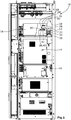
- the Figure 1 shows a section of a control cabinet with an analysis unit according to the invention.
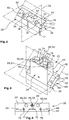
- the Figure 2 shows a connection housing part of the analysis unit according to the invention in a perspective view Figure 1 .
- the Figure 3 shows a perspective representation of a basic housing part of the analysis unit according to the invention Figure 1 .
- the Figure 4 shows a plan view of the basic housing part of the analysis unit according to the invention Figure 1 from underneath.
- the analysis unit shown is arranged in a switch cabinet 10 which contains various gas measuring devices 12, 14, 16.
- the upper of these gas measuring devices 12 is a flame ionization detector, in the outer housing 18 of which several further housing parts 20, 22, 24 to be mounted are arranged.
- a plurality of assembled housing parts 20 surround the space in which two flames of the flame ionization detector 12 are formed, the necessary gas supply lines and discharges and the necessary electronics for measurement and evaluation on the detector.
- a proportion of methane and a proportion of the total hydrocarbons present are determined in a known manner by conveying the measurement gas to the flame with a carrier gas stream containing hydrogen, among other things, where thermal ionization takes place, through which a measurable conductivity between two electrodes takes place is generated, which is a measure of the hydrocarbons present in the measuring gas.
- the measurement gas flow is divided into a first partial flow, which is conveyed directly to the first flame, so that a total flow of all hydrocarbons present can be determined there, and a second partial flow, which is fed to a second flame via a converter 26.
- a converter material which can be, for example, hopcalite, which is a mixture of copper oxide and manganese oxide, in the presence of hydrogen and oxygen to form carbon dioxide and water converted. While the remaining hydrocarbons are almost completely converted, only about 13% of the methane is converted in this converter 26, so that by appropriate conversion of the conductivity of the gas determined in the second flame, the proportion of methane in the total hydrocarbons present can be determined .
- this converter 26 contains the converter material which is to be introduced into correspondingly shaped channels of the converter 26.
- this material may have to be replaced during maintenance of the measuring devices, so that good accessibility is desired.
- connection housing 22 in which an inlet channel 34 and an outlet channel 36 are formed, into each of which one of the gas lines 30, 32 open.
- This connection housing 22 is fastened to a mounting plate 40 serving as a fastening plane 38 by means of screws 41, which extends perpendicular to a rear wall 42 of the switch cabinet 10 and is accordingly arranged perpendicular to the accessible front 28 of the switch cabinet 10.
- connection housing part 22 shown has a connection plane 44 which is tilted by 45 ° in the direction of the front side 28 in relation to the fastening plane 38 and which, in the area facing the rear wall 42, merges into a support surface 46 which extends parallel to the fastening plane 38.
- connection plane 44 of the connection housing part 22 two threaded bores 48 are formed in the outer area as well as a first circular recess 50 into which the inlet channel 34 opens, and a second circular recess 52 from which the outlet channel 36 extends through the connection housing part 22 and a slot-shaped recess 54 arranged therebetween is formed.
- connection housing part 22 and the channels 34, 36, bores 48 and recesses 50, 52, 54 formed therein are each arranged symmetrically to a plane of symmetry 56 which runs perpendicular to the fastening plane 38 and to the connection plane 44 and the connection housing part 22 is centrally divided into two equal sections Splits.
- connection housing part 22 On this connection housing part 22, a base housing part 24 of the converter 26 is mounted, which in the Figures 3 and 4 is shown.
- This has a flange plate 58, the flange surface 60 of which facing the connection housing part 22 has a connection plane after assembly which corresponds to the connection plane 44 of the connection housing part 22.
- This flange surface 60 merges into a surface 62, which in turn rests on the support surface 46 of the connection housing part 22 and accordingly also extends parallel to the fastening plane 38, so that the base housing part 24 can be placed on the connection housing part 22 during assembly, as a body 64 of the converter 26 extends upward from the flange plate 58 at a 45 ° angle, i.e. perpendicular to the mounting plane 38.
- a bore 66 is formed in the flange plate 58 to the right and left of the body 64 and extends perpendicular to the flange surface 60 through the flange plate 58 extends up to an opposite flange surface 64 and through which screws 68 are inserted and rotated into the threaded bores 48 during the assembly of the base housing part 24 on the connection housing part 22. It can be seen that these screws 68 are not only easily accessible from the frontal plane 28, but that there is also sufficient space for turning a wrench due to the inclined arrangement.
- the basic housing part 24 has four channels 70, 72, 74, 76 running parallel to one another, a first of which forms an inflow channel 70 which is fluidically connected to the inlet channel 34 of the connection housing part 22 via the axial recess 50, the two middle ones Channels serve as throughflow channels 72, 74 and the other outer channel serves as return flow channel 76, which in turn is fluidically connected to outlet channel 36 via the axial circular recess 52.
- the inflow channel 70 is connected to the adjacent throughflow channel 72, as is the return flow channel 76 to the adjacent throughflow channel 74 via axial recesses 78, which are located on the partition between the two channels 70, 72, 74, 76 at the end facing away from the connection housing part 22 Body 64 are formed.
- a connecting channel 80 is formed between the two throughflow channels 72, 74, which is arranged opposite the slot-shaped recess 54 of the connection housing part.
- the axial end of the body 64 is closed by a plate 82 which is fastened by means of screws 84 to the end of the body 64 of the base housing part 24 and thus closes the channels 70, 72, 74, 76.
- a gas enters the inlet channel 34 of the connection housing part 22, it flows into the inflow channel 70 and then flows in a meandering manner through the two throughflow channels 72, 74 into the return flow channel 76 and from there into the outlet channel 36.
- the converter material already described above for accelerating the reaction is present in each of these four channels 70, 72, 74, 76. In this way, a sufficient reaction path and a sufficient amount of converter material are made available for complete conversion of the non-methane hydrocarbons.
- FIG. 3 and 4 three further receiving openings 86, 88, 90 can be seen on the basic housing part 24, which extend parallel to the channels 70, 72, 74, 76.
- a temperature sensor 92 which is designed, for example, as a PTC element and is located between the two other receiving openings 88, 90, in each of which a heating cartridge 94 is arranged, which ensure that the Converter 26 a temperature of about 280 ° C prevails, which is the temperature at which an optimal reaction takes place.
- These channels are also closed by the plate 82.
- this is also designed so that it can be installed horizontally if the installation space available vertically is too small, by rotating it around its axis of symmetry by 180 ° and around compared to the installation position shown is installed tilted forward by 90 ° in the direction of the frontal plane.
- the channels are arranged in such a way that only the direction of flow through the basic housing part is exchanged, but otherwise no structural changes need to be made to the connection housing part or to the basic housing part. This leads to an increased number of identical parts to be produced, which in turn can reduce costs.
Landscapes
- Chemical & Material Sciences (AREA)
- Health & Medical Sciences (AREA)
- Life Sciences & Earth Sciences (AREA)
- Analytical Chemistry (AREA)
- General Health & Medical Sciences (AREA)
- Pathology (AREA)
- Immunology (AREA)
- Physics & Mathematics (AREA)
- Engineering & Computer Science (AREA)
- Biochemistry (AREA)
- General Physics & Mathematics (AREA)
- Combustion & Propulsion (AREA)
- Medicinal Chemistry (AREA)
- Food Science & Technology (AREA)
- Chemical Kinetics & Catalysis (AREA)
- Electrochemistry (AREA)
- Other Investigation Or Analysis Of Materials By Electrical Means (AREA)
- Sampling And Sample Adjustment (AREA)
Description
- Die Erfindung betrifft eine Analyseeinheit mit einer Frontalebene, von der aus die Analyseeinheit zugänglich ist und parallelen Befestigungsebenen, welche senkrecht zur Frontalebene angeordnet sind und einem Gasmessgerät.
- Derartige Analyseeinheiten sind üblicherweise in Schaltschränken angeordnet, welche an ihrer Frontseite eine Tür aufweisen, über die der Monteur oder das Bedienpersonal Zugang zu den einzelnen Messgeräten und deren Peripherieelementen erhält, so dass diese möglichst von der Frontseite erreichbar angebracht sind. Die Messgeräte und Peripherieelemente setzen sich zumeist aus mehreren Gehäuseteilen zusammen, von denen zumindest eines beispielsweise an einem der Schrankböden, welches dann als Befestigungsebene dient, befestigt wird, während die weiteren Gehäuseteile an dieses Teil montiert werden müssen. Je nach vorhandenem Bauraum ist dabei gegebenenfalls die Zugänglichkeit zu einzelnen Geräten nur eingeschränkt möglich, so dass sich insbesondere bei der Verwendung von Werkzeugen die Montage und Demontage schwierig gestaltet.
- So weist beispielsweise ein Flammenionisationsdetektor, wie er beispielsweise in der
DE 196 21 293 A1 beschrieben wird, neben dem Raum, in dem die Flamme oder die Flammen erzeugt werden und den dorthin führenden Gas- und Stromleitungen zur Versorgung der Elektroden sowie der Elemente zur Bestimmung der bei der Ionisierung freiwerdender Elektronen und der angeschlossenen elektronischen Auswerteeinheit einen Konverter auf, in welchem Kohlenwasserstoffmoleküle mit Ausnahme vor Methan mit Wasserstoffmolekülen und Sauerstoffmolekülen an einer Katalysatorfläche in Kohlendioxid und Wasser umgewandelt werden. Zur Bestimmung der Kohlenwasserstoffe wird eine Flamme des Flammenionisationsdetektors vom Abgasstrom durchströmt, während die andere Flamme von dem durch den Konverter geführten Abgasstrom durchströmt wird, so dass lediglich die Methananteile im Abgas an der anderen Flamme bestimmt werden, wobei die Umsetzungsgrade des Konverters zu beachten sind, welche bezüglich des Methans bei etwa 13 % liegen. Durch Differenzbildung kann daraufhin die Menge der Kohlenwasserstoffe ohne den Methananteil bestimmt werden. Obwohl diese Bauteile zu einem Flammenionisationsdetektor zusammengebaut werden, weisen sie verschiedene Gehäuseteilungen auf, um eine korrekte Montage sicherstellen zu können und bei Funktionsstörungen auch eine Zugänglichkeit einzelner Elemente des Flammenionisationsdetektors, wie die Katalysatoren des Konverters, sicherstellen zu können, ohne diesen komplett ausbauen zu müssen. - Des Weiteren ist aus der Veröffentlichung "Advanced CGA Solutions ACX Analyzer Systems for Emission Monitoring, Cement Applications and Process Measurement" eine Analyseeinheit bekannt, welche ein Gasmessgerät in einem Schrank aufweist, welches eine Befestigungsebene aufweist, über die die Gasanschlüsse erfolgen.
- Aus der Veröffentlichung "Siemens PA
01 2015 - Auch die
DE 20 2009 014 666 U1 offenbart einen Schaltschrank zur Abgasmessung, in dem entsprechend eine Analyseeinheit und ein Gasmessgerät angeordnet sind. - Nachteilig an den bekannten Systemen ist es, dass der Einbau de Messgeräte beziehungsweise der Gehäuseteile der Geräte unabhängig vom zur Verfügung stehenden Bauraum immer festliegt. Zusätzlich besteht häufig eine sehr schlechte Zugänglichkeit, wodurch Montagezeiten und Wartungszeiten deutlich erhöht werden.
- Es stellt sich daher die Aufgabe, eine Analyseeinheit so auszugestalten,dass die Messgeräte und/oder deren Peripheriegeräte einfach ein- und ausbaubar sind, indem die Zugänglichkeit dieser Geräte verbessert wird und dass es gleichzeitig möglich wird, die Einbaurichtung an den vorhandenen Bauraum anzupassen, ohne hierfür die Gehäuseteile ändern zu müssen.
- Diese Aufgabe wird durch eine Analyseeinheit mit den Merkmalen: des Hauptanspruchs 1 gelöst.
- Dadurch, dass das Gasmessgerät zumindest ein Anschlussgehäuseteil aufweist, durch welches sich ein Einlasskanal von der Befestigungsebene zu einer Anschlussebene und ein Auslasskanal von der Anschlussebene bis zur Befestigungsebene erstreckt, und ein Grundgehäuseteil mit einer Anschlussebene aufweist, die der Anschlussebene des Anschlussgehäuseteils entspricht und an der das Grundgehäuseteil gegen das Anschlussgehäuseteil anliegt, wobei im Grundgehäuseteil ein Zuströmkanal ausgebildet ist, der fluidisch über die Anschlussebene mit dem Einlasskanal des Anschlussgehäuseteils verbunden ist und ein Rückströmkanal ausgebildet ist, der fluidisch über die Anschlussebene mit dem Auslasskanal des Anschlussgehäuseteils verbunden ist, wobei die korrespondierenden Anschlussebenen im 45°-Winkel von der Befestigungsebene in Richtung zur Frontalebene gekippt angeordnet sind, bleibt ein Flansch, über den die beiden Gehäuseteile miteinander verbunden werden, von der Frontseite aus gut zugänglich. Insbesondere bleibt im Frontbereich Platz zur Nutzung von Werkzeugen, wie Schraubenschlüssel. Zusätzlich kann bei korrekter Anordnung der Gas führenden Kanäle das Grundgehäuse in zwei Richtungen auf das Anschtussgehäuseteil aufgebracht und befestigt werden, indem das Grundgehäuseteil um die eigene Achse gedreht und um 90° gekippt wird. So können zwei im 90°-Winkel zueinander stehende Erstreckungsrichtungen des Grundgehäuseteils bei der Montage hergestellt werden, wodurch eine Befestigung in Abhängigkeit des vorhandenen Bauraums ermöglicht wird.
- Vorzugsweise sind alle Bohrungen, Kanäle, Aufnahmeöffnungen oder Ausnehmungen im Anschlussgehäuseteil und im Grundgehäuseteil symmetrisch zu einer Symmetrieebene angeordnet, die senkrecht zur Befestigungsebene verläuft. Auf diese Weise wird für beide alternativen Einbaurichtungen eine korrekte Gasführung sichergestellt, ohne die aneinander zu befestigenden Bauteile anpassen zu müssen.
- Des Weiteren ist es vorteilhaft, wenn das Grundgehäuseteil eine Flanschplatte aufweist, deren erste Flanschfläche die Anschlussebene bildet und deren zweite Flanschfläche parallel zur Anschlussebene verläuft, wobei sich Bohrungen von der ersten Flanschfläche zur zweiten Flanschfläche durch die Flanschplatte erstrecken. Unabhängig von der Anbaurichtung des Grundgehäuseteils sind die Einsteckrichtung der Schrauben und damit die Richtung der Kraft zur Befestigung durch die Schrauben immer im 45°-Winkel zur Erstreckungsrichtung des Gehäuseteils ausgerichtet. Somit sind die Flanschfläche und damit die Schraubenköpfe zur Befestigung immer gut von der Frontseite aus zugänglich.
- Um die Montage besonders einfach durch ein Eindrehen der Schrauben sicherstellen zu können, sind in einer weiterführenden Ausführungsform am Anschlussgehäuseteil zwei Gewindebohrungen ausgebildet, in welche Schrauben drehbar sind, die sich durch die Bohrungen der Flanschplatte in die Gewindebohrungen erstrecken.
- Des Weiteren ist es vorteilhaft, wenn sich ein Körper des Grundgehäuseteils zwischen den beiden Bohrungen im 45° Winkel zu den Flanschflächen erstreckt, wobei das Grundgehäuseteil in zwei senkrecht zueinander angeordneten Positionen am Anschlussgehäuseteil befestigbar ist. Somit erstreckt sich das Grundgehäuseteil entweder im Schrank senkrecht zur Befestigungsebene beziehungsweise zum Schrankboden oder zur Frontseite. Je nach vorhandenem Bauraum beziehungsweise verwendetem Schaltschrank kann auf diese Weise mit Gleichteilen eine Montage erfolgen, wodurch Produktionskosten gesenkt werden können.
- In einer weiterführenden Ausbildung der Erfindung geht die schräge Anschlussebene des Anschlussgehäuseteils in eine Auflagefläche über, die parallel zur Befestigungsebene angeordnet sind. Entsprechend geht die schräge Anschlussebene des Grundgehäuseteils in eine Fläche über, die um 45° zur Anschlussebene abgewinkelt ist und die auf die Auflagefläche des Anschlussgehäuseteils in einer ersten Befestigungsposition aufsetzbar ist. Dies erleichtert den Montagevorgang, da das Grundgehäuseteil auf das Anschlussgehäuseteil bei der Montage aufgesetzt werden kann, ohne festgehalten werden zu müssen. Dennoch bleibt die schräge Anschlussebene zur Verbesserung der Erreichbarkeit.
- In einer bevorzugten Ausbildung der Erfindung ist im Zuströmkanal und/oder im Rückströmkanal des Grundgehauseteils Konvertermaterial angeordnet, welches zur Umwandlung von Kohlenwasserstoffen in Methan dient. Entsprechend dient das Grundgehäuseteil als Gehäuse eines Konverters, der entsprechend einfach montiert werden kann und dessen Erreichbarkeit beispielswiese zum Austausch des Konvertermaterials erhalten bleibt, ohne hierfür den gesamten Flammenionisationsdetektor ausbauen zu müssen. Durch die Anordnung des Konvertermaterials in zwei parallelen Kanälen kann die Länge eines Zylinders gekürzt und damit das benötigte Volumen zur Umwandlung auf kleinem Bauraum zur Verfügung gestellt werden.
- Diese Minimierung, insbesondere der axialen Baulänge eines Konverters, kann dadurch noch weiter gekürzt werden, dass im Grundgehäuseteil zwischen dem Zuströmkanal und dem Rückströmkanal zwei weitere parallel verlaufende Durchströmungskanäle ausgebildet sind, in denen Konvertermaterial angeordnet ist und die mit dem jeweils benachbarten Zuströmkanal beziehungsweise Rückströmkanal über axiale Ausnehmungen zwischen den vom Anschlussgehäuseteil weg weisenden Enden des Zuströmkanals und des benachbarten Durchströmungskanals und des Rückströmkanals und des benachbarten Durchströmungskanals miteinander verbunden sind.
- Eine vollständige Durchströmung aller vier Gaskanäle mit Konvertermaterial wird sichergestellt, indem im Grundgehäuseteil am zum Anschlussgehäuseteil weisenden Ende ein Verbindungskanal zwischen den beiden Durchströmungskanälen ausgebildet ist, so dass das Grundgehäuseteil mäanderförmig durchströmt ist. Entsprechend werden die Konverterkanäle nacheinander durchströmt, ohne das Grundgehäuseteil zu verlassen.
- Vorzugsweise ist an der Anschlussebene des Anschlussgehäuseteils eine erste kreisförmige Ausnehmung ausgebildet, in die der Einlasskanal mündet und welche mit dem Zuströmkanal des Grundgehäuseteils fluidisch verbunden ist und eine zweite kreisförmige Ausnehmung ausgebildet, in die der Rückströmkanal des Grundgehäuseteils mündet und welche mit dem Auslasskanal des Anschlussgehäuseteils fluidisch verbunden ist, und eine langlochförmige Ausnehmung ausgebildet, in die die beiden Durchströmungskanäle des Grundgehäuseteils münden. So wird der Gasstrom vor Erreichen des Konvertermaterials in den Kanälen des Grundgehäuseteils auf die gesamte Querschnittsfläche der das Konvertermaterial enthaltenden Kanäle erweitert, so dass hierin eine optimale Strömung erzielt wird. Zusätzlich wird ein erhöhter Druckverlust durch gleichmäßige zur Verfügung stehende Querschnitte vermieden.
- In einer weiteren Ausbildung der Erfindung sind der Zuströmkanal, der Rückströmkanal und die beiden Durchströmungskanäle mittels einer an ihrem zum Anschlussgehäuseteil entgegengesetzten Ende aufgeschraubten Platte verschlossen. Diese erleichtert die Herstellung des Grundgehäuseteils, in welches die Kanäle durch einfaches Bohren und Fräsen eingebracht werden können und somit die Zugänglichkeit und damit die Füllung der Kanäle mit dem Konvertermaterial.
- Des Weiteren kann vorteilhafterweise im Grundgehäuseteil zumindest eine erste Aufnahmeöffnung ausgebildet sein, in der eine Heizpatrone angeordnet ist und zumindest eine zweite Aufnahmeöffnung ausgebildet sein, in der ein Temperaturfühler angeordnet ist. Auf diese Weise kann im Konverter eine bevorzugte Temperatur von etwa 280°C erzeugt und überprüft werden, um eine optimale Umsetzung der Kohlenwasserstoffe sicherstellen zu können.
- Vorzugsweise ist das Gasmessgerät ein Flammenionisationsdetektor und das Grundgehäuseteil bildet entsprechend einen Konverter. Dieses Gasmessgerät ist üblicherweise aus verschiedenen Gehäuseteilen aufgebaut, deren Zugänglichkeit möglichst einzeln sicherzustellen ist, um eine Wartung vornehmen zu können.
- Es wird somit eine Analyseeinheit geschaffen, die aufgrund deutlich verbesserter zugänglichkeit sehr wartungs- und montagefreundlich ist. Zusätzlich werden aufgrund der möglichen zwei Anbaurichtungen Produktionsvorteile erzielt, da auch bei unterschiedlichen zur Verfügung stehenden Bauräumen optimale Einbaurichtungen mit Gleichteilen verwirklicht werden können. Besondere Vorteile werden insbesondere bei der Herstellung, Montage und Wartung eines Konverters eines Flammenionisationsdetektors erzielt.
- Ein Ausführungsbeispiel einer erfindungsgemäßen Analyseeinheit ist in den Figuren schematisch dargestellt und wird nachfolgend beschrieben.
- Die
Figur 1 zeigt einen Ausschnitt eines Schaltschranks mit einer erfindungsgemäßen Analyseeinheit. - Die
Figur 2 zeigt in perspektivischer Darstellung ein Anschlussgehäuseteil der erfindungsgemäßen Analyseeinheit ausFigur 1 . - Die
Figur 3 zeigt in perspektivischer Darstellung ein Grundgehäuseteil der erfindungsgemäßen Analyseeinheit ausFigur 1 . - Die
Figur 4 zeigt eine Draufsicht auf das Grundgehäuseteil der erfindungsgemäßen Analyseeinheit ausFigur 1 von unten. - Die dargestellte Analyseeinheit ist in einem Schaltschrank 10 angeordnet, der verschiedene Gasmessgeräte 12, 14, 16 enthält. Das obere dieser Gasmessgeräte 12 ist ein Flammenionisationsdetektor, in dessen Außengehäuse 18 mehrere weitere zu montierende Gehäuseteile 20, 22, 24 angeordnet sind. Mehrere zusammengesetzte Gehäuseteile 20 umgeben den Raum, in dem zwei Flammen des Flammenionisationsdetektors 12 ausgebildet sind, die notwendigen Gaszuleitungen und -ableitungen und die notwendige Elektronik zur Messung und Auswertung am Detektor. Über die beiden Flammen wird in bekannter Weise ein Anteil an Methan und ein Anteil der insgesamt vorhandenen Kohlenwasserstoffe bestimmt, indem das Messgas mit einem unter anderem Wasserstoff enthaltenden Trägergasstrom zur Flamme gefördert wird, wo eine thermische Ionisierung stattfindet, durch welche eine messbare Leitfähigkeit zwischen zwei Elektroden erzeugt wird, die ein Maß für die im Messgas vorhandenen Kohlenwasserstoffe ist.
- Der Messgasstrom wird jedoch in einen ersten Teilstrom, der direkt zur ersten Flamme gefördert wird, so dass dort ein Gesamtstrom aller vorhandenen Kohlenwasserstoffe ermittelt werden kann und einen zweiten Teilstrom aufgeteilt, der über einen Konverter 26 einer zweiten Flamme zugeführt wird. Im Konverter 26 werden alle Kohlenwasserstoffe außer Methan an einem Konvertermaterial, welches beispielsweise Hopkalit sein kann, welches eine Mischung aus Kupferoxid und Manganoxid ist, bei Vorhandensein von Wasserstoff und Sauerstoff zu Kohlendioxid und Wasser umgewandelt. Während die übrigen Kohlenwasserstoffe beinahe vollständig umgewandelt werden, wird in diesem Konverter 26 das Methan lediglich zu etwa 13 % umgesetzt, so dass durch entsprechende Umrechnung der ermittelten Leitfähigkeit des Gases in der zweiten Flamme auf den Anteil des Methans an den gesamt vorhandenen Kohlenwasserstoffen geschossen werden kann.
- Dieser Konverter 26 beinhaltet jedoch das Konvertermaterial, welches in entsprechend geformte Kanäle des Konverters 26 einzubringen ist. Zusätzlich ist dieses Material gegebenenfalls bei der Wartung der Messgeräte auszutauschen, so dass eine gute Zugänglichkeit gewünscht ist.
- Wie aus der
Figur 1 hervorgeht, kann von einer zugänglichen Frontalebene 28, die durch die Frontseite des Schaltschrankes 10 aufgespannt wird, Bedienpersonal das Innere des Schaltschrankes 10 erreichen. Von den Gehäuseteilen 20 erstrecken sich zwei Gasleitungen 30, 32 zu einem Anschlussgehäuse 22, in welchem ein Einlasskanal 34 und ein Auslasskanal 36 ausgebildet sind, in die jeweils eine der Gasleitungen 30, 32 münden. Dieses Anschlussgehäuse 22 ist auf einer als Befestigungsebene 38 dienenden Montageplatte 40 mittels Schrauben 41 befestigt, welche sich senkrecht zu einer Rückwand 42 des Schaltschrankes 10 erstreckt und entsprechend senkrecht zur zugänglichen Frontseite 28 des Schaltschrankes 10 angeordnet ist. - Das in der
Figur 2 dargestellte Anschlussgehäuseteil 22 weist eine zur Befestigungsebene 38 um 45° in Richtung der Frontseite 28 gekippte Anschlussebene 44 auf, welche im zur Rückwand 42 weisenden Bereich in eine Auflagefläche 46 übergeht, die sich parallel zur Befestigungsebene 38 erstreckt. An der Anschlussebene 44 des Anschlussgehäuseteils 22 sind zwei Gewindebohrungen 48 im äußeren Bereich sowie eine erste kreisförmige Ausnehmung 50 ausgebildet, in die der Einlasskanal 34 mündet, eine zweite kreisförmige Ausnehmung 52 ausgebildet, von der aus sich der Auslasskanal 36 durch das Anschlussgehäuseteil 22 erstreckt und eine dazwischen angeordnete langlochförmige Ausnehmung 54 ausgebildet. Das Anschlussgehäuseteil 22 sowie die darin ausgebildeten Kanäle 34, 36, Bohrungen 48 und Ausnehmungen 50, 52, 54 sind jeweils symmetrisch zu einer Symmetrieebene 56 angeordnet, welche senkrecht zur Befestigungsebene 38 und zur Anschlussebene 44 verläuft und das Anschlussgehäuseteil 22 zentral in zwei gleich große Abschnitte teilt. - Auf dieses Anschlussgehäuseteil 22 wird ein Grundgehäuseteil 24 des Konverters 26 montiert, welches in den
Figuren 3 und 4 dargestellt ist. Dieses weist eine Flanschplatte 58 auf, deren zum Anschlussgehäuseteil 22 weisende Flanschfläche 60 nach der Montage eine Anschlussebene aufweist, die der Anschlussebene 44 des Anschlussgehäuseteils 22 entspricht. Diese Flanschfläche 60 geht in eine Fläche 62 über, die wiederum auf der Auflagefläche 46 des Anschlussgehäuseteils 22 aufliegt und sich entsprechend ebenfalls parallel zur Befestigungsebene 38 erstreckt, so dass bei der Montage das Grundgehäuseteil 24 auf das Anschlussgehäuseteil 22 gestellt werden kann, denn ein Körper 64 des Konverters 26 erstreckt sich von der Flanschplatte 58 im 45°-Winkel nach oben, also senkrecht zu Befestigungsebene 38. In der Flanschplatte 58 ist rechts und links des Körpers 64 jeweils eine Bohrung 66 ausgebildet, die sich senkrecht zur Flanschfläche 60 durch die Flanschplatte 58 bis zu einer gegenüberliegenden Flanschfläche 64 erstreckt und durch welche bei der Montage des Grundgehäuseteils 24 an das Anschlussgehäuseteil 22 Schrauben 68 gesteckt und in die Gewindebohrungen 48 gedreht werden. Es ist ersichtlich, dass diese Schrauben 68 nicht nur gut von der Frontalebene 28 aus erreichbar sind, sondern auch ausreichend Platz für die Drehung eines Schraubenschlüssels durch die schräge Anordnung vorhanden ist. - Das Grundgehäuseteil 24 weist vier parallel zueinander verlaufende Kanäle 70, 72, 74, 76 auf, wovon ein erster einen Zuströmkanal 70 bildet, der über die axiale Ausnehmung 50 mit dem Einlasskanal 34 des Anschlussgehäuseteils 22 fluidisch verbunden ist, die beiden mittleren Kanäle als Durchströmungskanäle 72, 74, dienen und der andere äußere Kanal als Rückströmkanal 76 dient, der wiederum über die axiale kreisförmige Ausnehmung 52 mit dem Auslasskanal 36 fluidisch verbunden ist. Der Zuströmkanal 70 ist mit dem benachbarten Durchströmungskanal 72 ebenso wie der Rückströmkanal 76 mit dem benachbarten Durchströmungskanal 74 über axiale Ausnehmungen 78 miteinander verbunden, welche an der Trennwand zwischen den jeweils beiden Kanälen 70, 72, 74, 76 am vom Anschlussgehäuseteil 22 weg weisenden Ende des Körpers 64 ausgebildet sind. Am entgegengesetzten, also zum Anschlussgehäuse 22 weisenden Ende des Körpers 64 ist ein Verbindungskanal 80 zwischen den beiden Durchströmungskanälen 72, 74 ausgebildet, der gegenüberliegend zu der langlochförmigen Ausnehmung 54 des Anschlussgehäuseteils angeordnet ist. Das axiale Ende des Körpers 64 wird durch eine Platte 82 verschlossen, welche mittels Schrauben 84 auf dem Ende des Körpers 64 des Grundgehäuseteils 24 befestigt wird und so die Kanäle 70, 72, 74, 76 verschließt. Dies hat zur Folge, dass bei Eintritt eines Gases in den Einlasskanal 34 des Anschlussgehäuseteils 22 dieses in den Zuströmkanal 70 strömt um anschließend mäanderförmig durch die beiden Durchströmungskanäle 72, 74 in den Rückströmkanal 76 und von dort in den Auslasskanal 36 zu strömen. In allen diesen vier Kanälen 70, 72, 74, 76 ist jeweils das bereits oben beschriebene Konvertermaterial zur Beschleunigung der Reaktion vorhanden. Auf diese Weise werden eine ausreichende Reaktionsstrecke und ausreichend viel Konvertermaterial für eine vollständige Umsetzung der Nichtmethan-Kohlenwasserstoffe zur Verfügung gestellt.
- In den
Figuren 3 und 4 sind drei weitere Aufnahmeöffnungen 86, 88, 90 am Grundgehäuseteil 24 zu erkennen, die sich parallel zu den Kanälen 70, 72, 74, 76 erstrecken. In der mittleren in der Symmetrieebene 56 angeordneten Aufnahmeöffnung befindet sich ein Temperaturfühler 92, der beispielsweise als PTC-Element ausgebildet ist und sich zwischen den beiden anderen Aufnahmeöffnungen 88, 90 befindet, in denen jeweils eine Heizpatrone 94 angeordnet ist, welche dafür sorgen, dass im Konverter 26 eine Temperatur von etwa 280°C herrscht, welches die Temperatur ist, bei der eine optimale Reaktion verläuft. Auch diese Kanäle werden durch die Platte 82 verschlossen. - Neben der bereits beschriebenen guten Zugänglichkeit zum Einbau und Ausbau des Konverters 26 ist dieser auch so ausgeführt, dass er bei zu kleinem vertikal zur Verfügung stehendem Bauraum waagerecht eingebaut werden kann, indem er im Vergleich zur dargestellten Einbaulage um seine Symmetrieachse um 180° gedreht und um in Richtung der Frontalebene nach vorne um 90° gekippt eingebaut wird. Die Kanäle sind für diesen Fall so angeordnet, dass lediglich die Durchströmungsrichtung des Grundgehäuseteils getauscht wird, im Übrigen jedoch keine konstruktiven Änderungen am Anschlussgehäuseteil oder am Grundgehäuseteil vorgenommen werden müssen. Dies führt zu einer vergrößerten Anzahl herzustellender Gleichteile, wodurch wiederum Kosten reduziert werden können.
Claims (14)
- Analyseeinheit mit einer Frontalebene (28), von der aus die Analyseeinheit zugänglich ist und parallelen Befestigungsebenen (38), welche senkrecht zur Frontalebene (28) angeordnet sind, und
einem Gasmessgerät (12),
dadurch gekennzeichnet, dass
das Gasmessgerät (12) zumindest ein Anschlussgehäuseteil (22) aufweist, durch welches sich ein Einlasskanal (34) von einer der Befestigungsebenen (38) zu einer Anschlussebene (44) und ein Auslasskanal (36) von der Anschlussebene (44) bis zu der einen Befestigungsebene (38) erstreckt,
und ein Grundgehäuseteil (24) mit einer Anschlussebene aufweist, die der Anschlussebene (44) des Anschlussgehäuseteils (22) entspricht und an der das Grundgehäuseteil (24) gegen das Anschlussgehäuseteil (22) anliegt, wobei im Grundgehäuseteil (24) ein Zuströmkanal (70) ausgebildet ist, der fluidisch über die Anschlussebene (44) mit dem Einlasskanal (34) des Anschlussgehäuseteils (22) verbunden ist und ein Rückströmkanal (76) ausgebildet ist, der fluidisch über die Anschlussebene (44) mit dem Auslasskanal (36) des Anschlussgehäuseteils (22) verbunden ist,
wobei die korrespondierenden Anschlussebenen (44) im 45°-Winkel von der einen Befestigungsebene (38) in Richtung zur Frontalebene (28) gekippt angeordnet sind. - Analyseeinheit nach Anspruch 1,
dadurch gekennzeichnet, dass
alle Bohrungen (48, 66), Kanäle (34, 36, 70, 72, 74, 76), Aufnahmeöffnungen (86, 88, 90) oder Ausnehmungen (50, 52, 54) im Anschlussgehäuseteil (22) und im Grundgehäuseteil (24) symmetrisch zu einer zentralen Symmetrieebene (56) angeordnet sind, die senkrecht zu der einen Befestigungsebene (38) verläuft. - Analyseeinheit nach einem der Ansprüche 1 oder 2,
dadurch gekennzeichnet, dass
das Grundgehäuseteil (24) eine Flanschplatte (58) aufweist, deren erste Flanschfläche (60) die Anschlussebene (44) bildet und deren zweite Flanschfläche (62) parallel zur Anschlussebene (44) verläuft, wobei sich Bohrungen (66) von der ersten Flanschfläche (60) zur zweiten Flanschfläche (62) durch die Flanschplatte (58) erstrecken. - Analyseeinheit nach Anspruch 3,
dadurch gekennzeichnet, dass
am Anschlussgehäuseteil (22) zwei Gewindebohrungen (48) ausgebildet sind, in welche Schrauben (68) drehbar sind, die sich durch die Bohrungen (66) der Flanschplatte (58) in die Gewindebohrungen (48) erstrecken. - Analyseeinheit nach Anspruch 2 und 4, dadurch gekennzeichnet, dass sich ein Körper (64) des Grundgehäuseteils (24) zwischen den beiden Bohrungen (66) im 45° Winkel zu den Flanschflächen (60, 62) erstreckt, wobei das Grundgehäuseteil (24) in zwei senkrecht zueinander angeordneten Positionen am Anschlussgehäuseteil (22) befestigbar ist.
- Analyseeinheit nach einem der vorhergehenden Ansprüche,
dadurch gekennzeichnet, dass
die Anschlussebene (44) des Anschlussgehäuseteils (22) in eine Auflagefläche (46) des Anschlussgehäuseteils übergeht, die parallel zu der einen Befestigungsebene (38) angeordnet ist. - Analyseeinheit nach Anspruch 6,
dadurch gekennzeichnet, dass
die Anschlussebene (44) des Grundgehäuseteils (24) in eine Fläche (62) übergeht die um 45° zur Anschlussebene (44) abgewinkelt ist und die auf die Auflagefläche (46) des Anschlussgehäuseteils (22) in einer ersten Befestigungsposition aufsetzbar ist. - Analyseeinheit nach einem der vorhergehenden Ansprüche,
dadurch gekennzeichnet, dass
die Analyseeinheit ein Konvertermaterial, welches zur Umwandlung von Kohlenwasserstoffen in Methan geeignet ist, aufweist, wobei das Konvertermaterial im Zuströmkanal (70) und/oder im Rückströmkanal (76) des Grundgehäuseteils angeordnet ist. - Analyseeinheit nach Anspruch 8,
dadurch gekennzeichnet, dass
im Grundgehäuseteil (24) zwischen dem Zuströmkanal (70) und dem Rückströmkanal (76) zwei weitere parallel verlaufende Durchströmungskanäle (72, 74) ausgebildet sind, in denen das Konvertermaterial angeordnet ist und die mit dem jeweils benachbarten Zuströmkanal (70) beziehungsweise Rückströmkanal (76) über axiale Ausnehmungen (78) zwischen den vom Anschlussgehäuseteil (22) weg weisenden Enden des Zuströmkanals (70) und des benachbarten Durchströmungskanals (72) und des Rückströmkanals (76) und des benachbarten Durchströmungskanals (74) miteinander verbunden sind. - Analyseeinheit nach Anspruch 9,
dadurch gekennzeichnet, dass
im Grundgehäuseteil (24) am zum Anschlussgehäuseteil (22) weisenden Ende ein Verbindungskanal (80) zwischen den beiden Durchströmungskanälen (72, 74) ausgebildet ist, so dass das Grundgehäuseteil (24) mäanderförmig durchströmbar ist. - Analyseeinheit nach einem der Ansprüche 9 oder 10,
dadurch gekennzeichnet, dass
an der Anschlussebene (44) des Anschlussgehäuseteils (22) eine erste kreisförmige Ausnehmung (50) ausgebildet ist, in die der Einlasskanal (34) mündet und welche mit dem Zuströmkanal (70) des Grundgehäuseteils (24) fluidisch verbunden ist und eine zweite kreisförmige Ausnehmung (52) ausgebildet ist, in die der Rückströmkanal (76) des Grundgehäuspteils (24) mündet und welche mit dem Auslasskanal (36) des Anschlussgehäuseteils (22) fluidisch verbunden ist, und eine langlochförmige Ausnehmung (54) ausgebildet ist, in die die beiden Durchströmungskanäle (72, 74) des Grundgehäuseteils (24) münden. - Analyseeinheit nach einem der Ansprüche 9 bis 11,
dadurch gekennzeichnet, dass
der Zuströmkanal (70), der Rückströmkanal (76) und die beiden Durchströmungskanäle (72, 74) mittels einer an ihrem zum Anschlussgehäuseteil (22) entgegengesetzten Ende aufgeschraubten Platte (82) verschlossen sind. - Analyseeinheit nach einem der vorhergehenden Ansprüche,
dadurch gekennzeichnet, dass
die Analyseeinheit eine Heizpatrone (54) und einen Temperaturfühler (92) aufweist, wobei im Grundgehäuseteil (24) zumindest eine erste Aufnahmeöffnung (88; 90) ausgebildet ist, in der die Heizpatrone (94) angeordnet ist und zumindest eine zweite Aufnahmeöffnung (86) ausgebildet ist, in der der Temperaturfühler (92) angeordnet ist. - Analyseeinheit nach einem der vorhergehenden Ansprüche,
dadurch gekennzeichnet, dass
das Gasmessgerät (12) ein Flammenionisationsdetektor ist und das Grundgehäuseteil (24) einen Konverter (26) bildet.
Applications Claiming Priority (2)
| Application Number | Priority Date | Filing Date | Title |
|---|---|---|---|
| DE102016123925.9A DE102016123925B4 (de) | 2016-12-09 | 2016-12-09 | Winkelflansch für eine Analyseeinheit |
| PCT/EP2017/079759 WO2018104037A1 (de) | 2016-12-09 | 2017-11-20 | Analyseeinheit |
Publications (2)
| Publication Number | Publication Date |
|---|---|
| EP3552011A1 EP3552011A1 (de) | 2019-10-16 |
| EP3552011B1 true EP3552011B1 (de) | 2020-12-30 |
Family
ID=60421782
Family Applications (1)
| Application Number | Title | Priority Date | Filing Date |
|---|---|---|---|
| EP17801701.8A Active EP3552011B1 (de) | 2016-12-09 | 2017-11-20 | Analyseeinheit |
Country Status (7)
| Country | Link |
|---|---|
| US (1) | US10935530B2 (de) |
| EP (1) | EP3552011B1 (de) |
| JP (1) | JP6743303B2 (de) |
| KR (1) | KR102261241B1 (de) |
| CN (1) | CN110088616B (de) |
| DE (1) | DE102016123925B4 (de) |
| WO (1) | WO2018104037A1 (de) |
Family Cites Families (22)
| Publication number | Priority date | Publication date | Assignee | Title |
|---|---|---|---|---|
| US3468980A (en) * | 1966-01-17 | 1969-09-23 | Rohm & Haas | Flame resistant acrylic sheet containing cyclohexyl acrylate or methacrylate copolymer |
| US3692492A (en) * | 1971-02-08 | 1972-09-19 | Mine Safety Appliances Co | Apparatus for measuring carbon monoxide and total hydrocarbons in gas sample |
| DE2454285C3 (de) * | 1974-11-15 | 1979-10-04 | Siemens Ag, 1000 Berlin Und 8000 Muenchen | Konzentrationsbestimmung von Kohlenmonoxid |
| JPS62203457U (de) * | 1986-06-16 | 1987-12-25 | ||
| US5354692A (en) * | 1992-09-08 | 1994-10-11 | Pacific Biotech, Inc. | Analyte detection device including a hydrophobic barrier for improved fluid flow |
| JPH0835950A (ja) * | 1994-07-23 | 1996-02-06 | Horiba Ltd | 炭化水素分析方法とその分析装置およびメタン・ノンメタン成分の分離能向上のための装置 |
| CN1179199A (zh) * | 1995-02-06 | 1998-04-15 | 施蓝姆伯格工业公司 | 流体流调节方法及流体流调节器 |
| JPH09145610A (ja) * | 1995-11-17 | 1997-06-06 | Fuji Electric Co Ltd | ガス分析装置用のガスコンバータ |
| DE19621293A1 (de) | 1996-05-25 | 1997-11-27 | Pierburg Ag | Vorrichtung zur Messung von Brennkraftmaschinen-Abgaskomponenten |
| US6148613A (en) * | 1998-10-21 | 2000-11-21 | Alternative Fuel Systems, Inc. | Reversing flow catalytic converter for internal combustion engine |
| DE19857955A1 (de) | 1998-12-16 | 2000-06-21 | Pierburg Ag | Vorrichtung und Verfahren zur Analyse von Abgaskomponenten |
| DE19927818C2 (de) * | 1999-06-18 | 2003-10-23 | Bosch Gmbh Robert | Vorrichtung zur Messung der Masse eines strömenden Mediums |
| US7223298B2 (en) | 2005-03-17 | 2007-05-29 | Pgr Filters, L.L.C. | Filter assembly for pipelines |
| AT506308B1 (de) * | 2007-12-12 | 2009-08-15 | Vaillant Austria Gmbh | Befestigungsvorrichtung und verfahren zum anschluss hydraulischer leitungen |
| US8263006B2 (en) * | 2009-05-31 | 2012-09-11 | Corning Incorporated | Reactor with upper and lower manifold structures |
| DE202009014666U1 (de) * | 2009-10-30 | 2010-03-18 | Maha-Aip Gmbh & Co. Kg | Schaltschrank bzw. Geräteträgeranordnung, insbesondere zur Abgasmessung bei Kraftfahrzeugen |
| CN102621272A (zh) * | 2011-12-08 | 2012-08-01 | 河北先河环保科技股份有限公司 | 一种大气碳氢化合物在线分析仪 |
| CN102620791B (zh) * | 2012-04-12 | 2016-03-09 | 新奥气化采煤有限公司 | 计量多相流中气体流量的方法和系统、多相流分配装置 |
| DE102013006548B4 (de) * | 2013-04-16 | 2022-02-03 | Dräger Safety AG & Co. KGaA | Messvorrichtung, Reaktionsträger und Messverfahren |
| DE102013012731A1 (de) | 2013-08-01 | 2015-02-05 | Krohne Messtechnik Gmbh | Verfahren zur Herstellung eines Gaskonverters und entsprechender Gaskonverter |
| DE102014100691B3 (de) * | 2014-01-22 | 2015-01-08 | Avl Emission Test Systems Gmbh | Vorrichtung zur Bestimmung der Konzentration zumindest eines Gases in einem Probengasstrom mittels Infrarotabsorptionsspektroskopie |
| CN104849374B (zh) * | 2015-06-11 | 2016-09-28 | 广东俐峰环保科技有限公司 | 非甲烷总烃分析设备及方法 |
-
2016
- 2016-12-09 DE DE102016123925.9A patent/DE102016123925B4/de active Active
-
2017
- 2017-11-20 US US16/462,939 patent/US10935530B2/en active Active
- 2017-11-20 WO PCT/EP2017/079759 patent/WO2018104037A1/de not_active Ceased
- 2017-11-20 KR KR1020197009581A patent/KR102261241B1/ko active Active
- 2017-11-20 CN CN201780065212.XA patent/CN110088616B/zh active Active
- 2017-11-20 EP EP17801701.8A patent/EP3552011B1/de active Active
- 2017-11-20 JP JP2019529598A patent/JP6743303B2/ja active Active
Non-Patent Citations (1)
| Title |
|---|
| None * |
Also Published As
| Publication number | Publication date |
|---|---|
| CN110088616B (zh) | 2022-03-08 |
| KR102261241B1 (ko) | 2021-06-07 |
| JP2019537022A (ja) | 2019-12-19 |
| WO2018104037A1 (de) | 2018-06-14 |
| KR20190057314A (ko) | 2019-05-28 |
| EP3552011A1 (de) | 2019-10-16 |
| US20200064320A1 (en) | 2020-02-27 |
| CN110088616A (zh) | 2019-08-02 |
| DE102016123925B4 (de) | 2019-03-28 |
| US10935530B2 (en) | 2021-03-02 |
| JP6743303B2 (ja) | 2020-08-19 |
| DE102016123925A1 (de) | 2018-06-14 |
Similar Documents
| Publication | Publication Date | Title |
|---|---|---|
| DE112010001778B4 (de) | Mehrfachanschluss-Inline-Durchflusszelle zur Verwendung bei der Beobachtung mehrerer Parameter in einer hygienischen Prozesslinie | |
| DE19848542C2 (de) | Sonde für die Probenahme | |
| EP2317833B1 (de) | Schaltschrank bzw. Geräteträgeranordnung, insbesondere zur Abgasmessung bei Kraftfahrzeugen | |
| DE10203310A1 (de) | Probenahmesystem für Abgassensoren | |
| EP1464908B1 (de) | Fixierung einer Wärmetauscherkassette | |
| EP3552011B1 (de) | Analyseeinheit | |
| DE69633251T2 (de) | Analyseapparat | |
| EP1174625B1 (de) | Dosierventilanordnung zum Speisen eines gasförmigen Mediums in ein in einem Kraftfahrzeug eingesetztes Brennstoffzellen-System | |
| DE3609929C1 (de) | Prozessanalysator-System | |
| EP3465129A1 (de) | Schaltschrank für abgasmessanlagen | |
| WO2007033821A1 (de) | Mediendecke, insbesondere für labors, sowie verfahren zur montage einer solchen | |
| DE102006007103A1 (de) | Modulares Druckluft-Wartungsgerät | |
| DE4417665A1 (de) | Meßanordnung zur Untersuchung gasförmiger Medien | |
| EP3403476B1 (de) | Schaltschrank für abgasmessanlagen | |
| EP4008954A2 (de) | Brenneranordnung zur verbrennung von wasserstoff enthaltendem brenngas und brennerkörper | |
| DE102004050191A1 (de) | Anordnung zur Überwachung einer Anlage auf thermische Belastung | |
| EP3465128B1 (de) | Schaltschrank für abgasmessanlagen | |
| DE10060705A1 (de) | Motorunabhängiges Heizgerät eines Kraftfahrzeuges | |
| EP3880535B1 (de) | Klimatisierungsanordnung für ein schienenfahrzeug | |
| WO2023025659A1 (de) | Verfahren zur befestigung eines gehäuses für ein messgerät der prozess- oder automatisierungstechnik an einer wandung | |
| DE102005047741A1 (de) | Elektrischer Schalter | |
| AT521524B1 (de) | Gasmischvorrichtung zur Kalibrierung von Gasanalysatoren | |
| EP3698075B1 (de) | Steuerschrank | |
| AT502948B1 (de) | Vorrichtung zum messen zumindest eines flüchtigen bestandteils einer wässrigen lösung, insbesondere zum messen von alkohol | |
| EP1148565A2 (de) | Brennstoffzellensystem |
Legal Events
| Date | Code | Title | Description |
|---|---|---|---|
| STAA | Information on the status of an ep patent application or granted ep patent |
Free format text: STATUS: UNKNOWN |
|
| STAA | Information on the status of an ep patent application or granted ep patent |
Free format text: STATUS: THE INTERNATIONAL PUBLICATION HAS BEEN MADE |
|
| PUAI | Public reference made under article 153(3) epc to a published international application that has entered the european phase |
Free format text: ORIGINAL CODE: 0009012 |
|
| STAA | Information on the status of an ep patent application or granted ep patent |
Free format text: STATUS: REQUEST FOR EXAMINATION WAS MADE |
|
| 17P | Request for examination filed |
Effective date: 20190618 |
|
| AK | Designated contracting states |
Kind code of ref document: A1 Designated state(s): AL AT BE BG CH CY CZ DE DK EE ES FI FR GB GR HR HU IE IS IT LI LT LU LV MC MK MT NL NO PL PT RO RS SE SI SK SM TR |
|
| AX | Request for extension of the european patent |
Extension state: BA ME |
|
| DAV | Request for validation of the european patent (deleted) | ||
| DAX | Request for extension of the european patent (deleted) | ||
| STAA | Information on the status of an ep patent application or granted ep patent |
Free format text: STATUS: EXAMINATION IS IN PROGRESS |
|
| 17Q | First examination report despatched |
Effective date: 20200414 |
|
| GRAP | Despatch of communication of intention to grant a patent |
Free format text: ORIGINAL CODE: EPIDOSNIGR1 |
|
| STAA | Information on the status of an ep patent application or granted ep patent |
Free format text: STATUS: GRANT OF PATENT IS INTENDED |
|
| INTG | Intention to grant announced |
Effective date: 20200723 |
|
| GRAS | Grant fee paid |
Free format text: ORIGINAL CODE: EPIDOSNIGR3 |
|
| GRAA | (expected) grant |
Free format text: ORIGINAL CODE: 0009210 |
|
| STAA | Information on the status of an ep patent application or granted ep patent |
Free format text: STATUS: THE PATENT HAS BEEN GRANTED |
|
| AK | Designated contracting states |
Kind code of ref document: B1 Designated state(s): AL AT BE BG CH CY CZ DE DK EE ES FI FR GB GR HR HU IE IS IT LI LT LU LV MC MK MT NL NO PL PT RO RS SE SI SK SM TR |
|
| REG | Reference to a national code |
Ref country code: GB Ref legal event code: FG4D Free format text: NOT ENGLISH |
|
| REG | Reference to a national code |
Ref country code: AT Ref legal event code: REF Ref document number: 1350430 Country of ref document: AT Kind code of ref document: T Effective date: 20210115 |
|
| REG | Reference to a national code |
Ref country code: DE Ref legal event code: R096 Ref document number: 502017008880 Country of ref document: DE |
|
| REG | Reference to a national code |
Ref country code: IE Ref legal event code: FG4D Free format text: LANGUAGE OF EP DOCUMENT: GERMAN |
|
| PG25 | Lapsed in a contracting state [announced via postgrant information from national office to epo] |
Ref country code: GR Free format text: LAPSE BECAUSE OF FAILURE TO SUBMIT A TRANSLATION OF THE DESCRIPTION OR TO PAY THE FEE WITHIN THE PRESCRIBED TIME-LIMIT Effective date: 20210331 Ref country code: NO Free format text: LAPSE BECAUSE OF FAILURE TO SUBMIT A TRANSLATION OF THE DESCRIPTION OR TO PAY THE FEE WITHIN THE PRESCRIBED TIME-LIMIT Effective date: 20210330 Ref country code: RS Free format text: LAPSE BECAUSE OF FAILURE TO SUBMIT A TRANSLATION OF THE DESCRIPTION OR TO PAY THE FEE WITHIN THE PRESCRIBED TIME-LIMIT Effective date: 20201230 Ref country code: FI Free format text: LAPSE BECAUSE OF FAILURE TO SUBMIT A TRANSLATION OF THE DESCRIPTION OR TO PAY THE FEE WITHIN THE PRESCRIBED TIME-LIMIT Effective date: 20201230 |
|
| PG25 | Lapsed in a contracting state [announced via postgrant information from national office to epo] |
Ref country code: LV Free format text: LAPSE BECAUSE OF FAILURE TO SUBMIT A TRANSLATION OF THE DESCRIPTION OR TO PAY THE FEE WITHIN THE PRESCRIBED TIME-LIMIT Effective date: 20201230 Ref country code: SE Free format text: LAPSE BECAUSE OF FAILURE TO SUBMIT A TRANSLATION OF THE DESCRIPTION OR TO PAY THE FEE WITHIN THE PRESCRIBED TIME-LIMIT Effective date: 20201230 Ref country code: BG Free format text: LAPSE BECAUSE OF FAILURE TO SUBMIT A TRANSLATION OF THE DESCRIPTION OR TO PAY THE FEE WITHIN THE PRESCRIBED TIME-LIMIT Effective date: 20210330 |
|
| REG | Reference to a national code |
Ref country code: NL Ref legal event code: MP Effective date: 20201230 |
|
| PG25 | Lapsed in a contracting state [announced via postgrant information from national office to epo] |
Ref country code: HR Free format text: LAPSE BECAUSE OF FAILURE TO SUBMIT A TRANSLATION OF THE DESCRIPTION OR TO PAY THE FEE WITHIN THE PRESCRIBED TIME-LIMIT Effective date: 20201230 |
|
| REG | Reference to a national code |
Ref country code: LT Ref legal event code: MG9D |
|
| PG25 | Lapsed in a contracting state [announced via postgrant information from national office to epo] |
Ref country code: LT Free format text: LAPSE BECAUSE OF FAILURE TO SUBMIT A TRANSLATION OF THE DESCRIPTION OR TO PAY THE FEE WITHIN THE PRESCRIBED TIME-LIMIT Effective date: 20201230 Ref country code: CZ Free format text: LAPSE BECAUSE OF FAILURE TO SUBMIT A TRANSLATION OF THE DESCRIPTION OR TO PAY THE FEE WITHIN THE PRESCRIBED TIME-LIMIT Effective date: 20201230 Ref country code: EE Free format text: LAPSE BECAUSE OF FAILURE TO SUBMIT A TRANSLATION OF THE DESCRIPTION OR TO PAY THE FEE WITHIN THE PRESCRIBED TIME-LIMIT Effective date: 20201230 Ref country code: SK Free format text: LAPSE BECAUSE OF FAILURE TO SUBMIT A TRANSLATION OF THE DESCRIPTION OR TO PAY THE FEE WITHIN THE PRESCRIBED TIME-LIMIT Effective date: 20201230 Ref country code: RO Free format text: LAPSE BECAUSE OF FAILURE TO SUBMIT A TRANSLATION OF THE DESCRIPTION OR TO PAY THE FEE WITHIN THE PRESCRIBED TIME-LIMIT Effective date: 20201230 Ref country code: PT Free format text: LAPSE BECAUSE OF FAILURE TO SUBMIT A TRANSLATION OF THE DESCRIPTION OR TO PAY THE FEE WITHIN THE PRESCRIBED TIME-LIMIT Effective date: 20210430 |
|
| PG25 | Lapsed in a contracting state [announced via postgrant information from national office to epo] |
Ref country code: PL Free format text: LAPSE BECAUSE OF FAILURE TO SUBMIT A TRANSLATION OF THE DESCRIPTION OR TO PAY THE FEE WITHIN THE PRESCRIBED TIME-LIMIT Effective date: 20201230 |
|
| PG25 | Lapsed in a contracting state [announced via postgrant information from national office to epo] |
Ref country code: IS Free format text: LAPSE BECAUSE OF FAILURE TO SUBMIT A TRANSLATION OF THE DESCRIPTION OR TO PAY THE FEE WITHIN THE PRESCRIBED TIME-LIMIT Effective date: 20210430 |
|
| REG | Reference to a national code |
Ref country code: DE Ref legal event code: R097 Ref document number: 502017008880 Country of ref document: DE |
|
| PG25 | Lapsed in a contracting state [announced via postgrant information from national office to epo] |
Ref country code: AL Free format text: LAPSE BECAUSE OF FAILURE TO SUBMIT A TRANSLATION OF THE DESCRIPTION OR TO PAY THE FEE WITHIN THE PRESCRIBED TIME-LIMIT Effective date: 20201230 |
|
| PLBE | No opposition filed within time limit |
Free format text: ORIGINAL CODE: 0009261 |
|
| STAA | Information on the status of an ep patent application or granted ep patent |
Free format text: STATUS: NO OPPOSITION FILED WITHIN TIME LIMIT |
|
| PG25 | Lapsed in a contracting state [announced via postgrant information from national office to epo] |
Ref country code: DK Free format text: LAPSE BECAUSE OF FAILURE TO SUBMIT A TRANSLATION OF THE DESCRIPTION OR TO PAY THE FEE WITHIN THE PRESCRIBED TIME-LIMIT Effective date: 20201230 |
|
| 26N | No opposition filed |
Effective date: 20211001 |
|
| PG25 | Lapsed in a contracting state [announced via postgrant information from national office to epo] |
Ref country code: ES Free format text: LAPSE BECAUSE OF FAILURE TO SUBMIT A TRANSLATION OF THE DESCRIPTION OR TO PAY THE FEE WITHIN THE PRESCRIBED TIME-LIMIT Effective date: 20201230 |
|
| PG25 | Lapsed in a contracting state [announced via postgrant information from national office to epo] |
Ref country code: SI Free format text: LAPSE BECAUSE OF FAILURE TO SUBMIT A TRANSLATION OF THE DESCRIPTION OR TO PAY THE FEE WITHIN THE PRESCRIBED TIME-LIMIT Effective date: 20201230 |
|
| PG25 | Lapsed in a contracting state [announced via postgrant information from national office to epo] |
Ref country code: IS Free format text: LAPSE BECAUSE OF FAILURE TO SUBMIT A TRANSLATION OF THE DESCRIPTION OR TO PAY THE FEE WITHIN THE PRESCRIBED TIME-LIMIT Effective date: 20210430 |
|
| REG | Reference to a national code |
Ref country code: DE Ref legal event code: R119 Ref document number: 502017008880 Country of ref document: DE |
|
| PG25 | Lapsed in a contracting state [announced via postgrant information from national office to epo] |
Ref country code: MC Free format text: LAPSE BECAUSE OF FAILURE TO SUBMIT A TRANSLATION OF THE DESCRIPTION OR TO PAY THE FEE WITHIN THE PRESCRIBED TIME-LIMIT Effective date: 20201230 |
|
| REG | Reference to a national code |
Ref country code: CH Ref legal event code: PL |
|
| PG25 | Lapsed in a contracting state [announced via postgrant information from national office to epo] |
Ref country code: LU Free format text: LAPSE BECAUSE OF NON-PAYMENT OF DUE FEES Effective date: 20211120 Ref country code: BE Free format text: LAPSE BECAUSE OF NON-PAYMENT OF DUE FEES Effective date: 20211130 |
|
| REG | Reference to a national code |
Ref country code: BE Ref legal event code: MM Effective date: 20211130 |
|
| PG25 | Lapsed in a contracting state [announced via postgrant information from national office to epo] |
Ref country code: LI Free format text: LAPSE BECAUSE OF NON-PAYMENT OF DUE FEES Effective date: 20211130 Ref country code: CH Free format text: LAPSE BECAUSE OF NON-PAYMENT OF DUE FEES Effective date: 20211130 |
|
| PG25 | Lapsed in a contracting state [announced via postgrant information from national office to epo] |
Ref country code: IE Free format text: LAPSE BECAUSE OF NON-PAYMENT OF DUE FEES Effective date: 20211120 Ref country code: DE Free format text: LAPSE BECAUSE OF NON-PAYMENT OF DUE FEES Effective date: 20220601 |
|
| PG25 | Lapsed in a contracting state [announced via postgrant information from national office to epo] |
Ref country code: FR Free format text: LAPSE BECAUSE OF NON-PAYMENT OF DUE FEES Effective date: 20211130 |
|
| P01 | Opt-out of the competence of the unified patent court (upc) registered |
Effective date: 20230504 |
|
| PG25 | Lapsed in a contracting state [announced via postgrant information from national office to epo] |
Ref country code: NL Free format text: LAPSE BECAUSE OF NON-PAYMENT OF DUE FEES Effective date: 20201230 Ref country code: CY Free format text: LAPSE BECAUSE OF FAILURE TO SUBMIT A TRANSLATION OF THE DESCRIPTION OR TO PAY THE FEE WITHIN THE PRESCRIBED TIME-LIMIT Effective date: 20201230 |
|
| PG25 | Lapsed in a contracting state [announced via postgrant information from national office to epo] |
Ref country code: SM Free format text: LAPSE BECAUSE OF FAILURE TO SUBMIT A TRANSLATION OF THE DESCRIPTION OR TO PAY THE FEE WITHIN THE PRESCRIBED TIME-LIMIT Effective date: 20201230 Ref country code: HU Free format text: LAPSE BECAUSE OF FAILURE TO SUBMIT A TRANSLATION OF THE DESCRIPTION OR TO PAY THE FEE WITHIN THE PRESCRIBED TIME-LIMIT; INVALID AB INITIO Effective date: 20171120 |
|
| REG | Reference to a national code |
Ref country code: AT Ref legal event code: MM01 Ref document number: 1350430 Country of ref document: AT Kind code of ref document: T Effective date: 20221120 |
|
| PG25 | Lapsed in a contracting state [announced via postgrant information from national office to epo] |
Ref country code: AT Free format text: LAPSE BECAUSE OF NON-PAYMENT OF DUE FEES Effective date: 20221120 |
|
| PG25 | Lapsed in a contracting state [announced via postgrant information from national office to epo] |
Ref country code: MK Free format text: LAPSE BECAUSE OF FAILURE TO SUBMIT A TRANSLATION OF THE DESCRIPTION OR TO PAY THE FEE WITHIN THE PRESCRIBED TIME-LIMIT Effective date: 20201230 |
|
| PG25 | Lapsed in a contracting state [announced via postgrant information from national office to epo] |
Ref country code: TR Free format text: LAPSE BECAUSE OF FAILURE TO SUBMIT A TRANSLATION OF THE DESCRIPTION OR TO PAY THE FEE WITHIN THE PRESCRIBED TIME-LIMIT Effective date: 20201230 |
|
| PG25 | Lapsed in a contracting state [announced via postgrant information from national office to epo] |
Ref country code: MT Free format text: LAPSE BECAUSE OF FAILURE TO SUBMIT A TRANSLATION OF THE DESCRIPTION OR TO PAY THE FEE WITHIN THE PRESCRIBED TIME-LIMIT Effective date: 20201230 |
|
| PGFP | Annual fee paid to national office [announced via postgrant information from national office to epo] |
Ref country code: GB Payment date: 20241120 Year of fee payment: 8 |
|
| PGFP | Annual fee paid to national office [announced via postgrant information from national office to epo] |
Ref country code: IT Payment date: 20241126 Year of fee payment: 8 |