EP3551850B1 - Verfahren zum modifizieren einer turbine - Google Patents
Verfahren zum modifizieren einer turbine Download PDFInfo
- Publication number
- EP3551850B1 EP3551850B1 EP18704502.6A EP18704502A EP3551850B1 EP 3551850 B1 EP3551850 B1 EP 3551850B1 EP 18704502 A EP18704502 A EP 18704502A EP 3551850 B1 EP3551850 B1 EP 3551850B1
- Authority
- EP
- European Patent Office
- Prior art keywords
- rotor blade
- replacement
- turbine
- ring
- rotor
- Prior art date
- Legal status (The legal status is an assumption and is not a legal conclusion. Google has not performed a legal analysis and makes no representation as to the accuracy of the status listed.)
- Active
Links
Images
Classifications
-
- F—MECHANICAL ENGINEERING; LIGHTING; HEATING; WEAPONS; BLASTING
- F01—MACHINES OR ENGINES IN GENERAL; ENGINE PLANTS IN GENERAL; STEAM ENGINES
- F01D—NON-POSITIVE DISPLACEMENT MACHINES OR ENGINES, e.g. STEAM TURBINES
- F01D5/00—Blades; Blade-carrying members; Heating, heat-insulating, cooling or antivibration means on the blades or the members
- F01D5/02—Blade-carrying members, e.g. rotors
- F01D5/025—Fixing blade carrying members on shafts
-
- B—PERFORMING OPERATIONS; TRANSPORTING
- B23—MACHINE TOOLS; METAL-WORKING NOT OTHERWISE PROVIDED FOR
- B23P—METAL-WORKING NOT OTHERWISE PROVIDED FOR; COMBINED OPERATIONS; UNIVERSAL MACHINE TOOLS
- B23P6/00—Restoring or reconditioning objects
- B23P6/002—Repairing turbine components, e.g. moving or stationary blades, rotors
-
- F—MECHANICAL ENGINEERING; LIGHTING; HEATING; WEAPONS; BLASTING
- F01—MACHINES OR ENGINES IN GENERAL; ENGINE PLANTS IN GENERAL; STEAM ENGINES
- F01D—NON-POSITIVE DISPLACEMENT MACHINES OR ENGINES, e.g. STEAM TURBINES
- F01D5/00—Blades; Blade-carrying members; Heating, heat-insulating, cooling or antivibration means on the blades or the members
- F01D5/12—Blades
- F01D5/14—Form or construction
- F01D5/141—Shape, i.e. outer, aerodynamic form
- F01D5/142—Shape, i.e. outer, aerodynamic form of the blades of successive rotor or stator blade-rows
- F01D5/143—Contour of the outer or inner working fluid flow path wall, i.e. shroud or hub contour
-
- F—MECHANICAL ENGINEERING; LIGHTING; HEATING; WEAPONS; BLASTING
- F05—INDEXING SCHEMES RELATING TO ENGINES OR PUMPS IN VARIOUS SUBCLASSES OF CLASSES F01-F04
- F05D—INDEXING SCHEME FOR ASPECTS RELATING TO NON-POSITIVE-DISPLACEMENT MACHINES OR ENGINES, GAS-TURBINES OR JET-PROPULSION PLANTS
- F05D2230/00—Manufacture
- F05D2230/60—Assembly methods
- F05D2230/64—Assembly methods using positioning or alignment devices for aligning or centring, e.g. pins
-
- F—MECHANICAL ENGINEERING; LIGHTING; HEATING; WEAPONS; BLASTING
- F05—INDEXING SCHEMES RELATING TO ENGINES OR PUMPS IN VARIOUS SUBCLASSES OF CLASSES F01-F04
- F05D—INDEXING SCHEME FOR ASPECTS RELATING TO NON-POSITIVE-DISPLACEMENT MACHINES OR ENGINES, GAS-TURBINES OR JET-PROPULSION PLANTS
- F05D2230/00—Manufacture
- F05D2230/80—Repairing, retrofitting or upgrading methods
-
- F—MECHANICAL ENGINEERING; LIGHTING; HEATING; WEAPONS; BLASTING
- F05—INDEXING SCHEMES RELATING TO ENGINES OR PUMPS IN VARIOUS SUBCLASSES OF CLASSES F01-F04
- F05D—INDEXING SCHEME FOR ASPECTS RELATING TO NON-POSITIVE-DISPLACEMENT MACHINES OR ENGINES, GAS-TURBINES OR JET-PROPULSION PLANTS
- F05D2270/00—Control
- F05D2270/01—Purpose of the control system
- F05D2270/20—Purpose of the control system to optimize the performance of a machine
Definitions
- the invention relates to a method for modifying a turbine.
- Thermal flow machines also called turbo machines are understood to mean machines in which energy is transferred between a working medium (liquid or gas) and the thermal flow machine in an open space through a flow according to the laws of fluid dynamics via the detour of kinetic energy.
- Such a thermal fluid machine such as a gas turbine
- a compressor can have a compressor and a turbine.
- the compressor is designed to compress a gaseous working medium, while the turbine converts the internal energy of a flowing working medium into mechanical energy, which it emits via a turbine shaft.
- Thermal turbomachines have blading that includes the entirety of the blades, e.g. the turbine. A distinction is made between rotor blades and guide blades. A ring of rotor blades with the associated ring of guide blades is referred to as a step.
- the blading of the turbine and / or the compressor can be multi-stage.
- the guide vanes are permanently installed in a housing of the turbine and guide the working fluid at the optimum angle onto the rotor blades, which are located on rotating shafts.
- the mechanically usable power is coupled between the thermal flow machine and the working fluid via the rotor blades.
- a five-stage turbine for example, has five rotor blade rings.
- the guide vane rings are in the case of compressors mostly assigned to the preceding rotor blade ring, in the case of turbines mostly to the following rotor blade ring.
- Blades i.e. moving or guide vanes
- Blades have an airfoil, a platform attached to the airfoil, a foot attached to the platform with an attachment portion for attaching the blade to the housing or to the rotor of the turbine.
- an original rotor blade ring at a first rotor blade position is replaced by a replacement rotor blade ring at a second rotor blade position, with the housing being retained the second rotor blade position is arranged at a distance from the first rotor blade position along a direction of extent of a rotor shaft of the turbine in the flow direction of a working medium flowing through the turbine.
- the replacement rotor blade ring has a larger outer diameter than the original rotor blade ring. They are used without changing the housing, i.e. while maintaining the conical opening angle. This is only possible because, due to the housing conicity and the rotor blades now arranged further downstream, the distance between the rotor axis and an inner diameter of the housing is increased compared to the distance at the first rotor blade position. An adaptation to an already existing enlarged inside diameter of the housing thus takes place, so that a particularly energy-efficient turbine is easily provided.
- a separate component is preferably used as the positioning element.
- the position of the replacement rotor blade ring can thus be determined without modifying the rotor disk of the replacement rotor blade ring.
- a positioning element designed as a spacer disk or ring is preferably arranged in the rotor shaft for fixing the replacement rotor blade ring at the second rotor blade position.
- the replacement blade ring can be fixed at the second blade position in a particularly simple manner, so that with the replacement blades the axial position of the inner end of the blade in relation to the axial position of the blade root can be maintained unchanged as with the original blades. This reduces the design effort to determine the shape of the replacement blades.
- a positioning element designed as a spacer disk or ring is preferably used.
- a positioning element that is particularly easy to manufacture can thus be used.
- the positioning element is preferably molded onto the replacement rotor blade ring. There is therefore no need to assemble additional components.
- the positioning element is preferably formed by an extension on a balcony of a foot of a replacement rotor blade of the replacement rotor blade ring.
- the roots of the replacement blades are axially altered by lengthening them on their upstream side and shortening them on their downstream side.
- the rotor disk in which the rotor blades are held in a conventional manner, can accordingly continue to be used unchanged without a spacer disk having to be inserted in the rotor shaft.
- the replacement blades are then arranged in the groove of the rotor disk in such a way that their blade is arranged axially further downstream than the blade of the original blades was.
- the blade blades can be lengthened on the tip side by build-up welding or other suitable additive processes.
- the positioning element can thus be formed by a particularly simple modification of a rotor blade.
- a root of a replacement blade of the replacement blade ring is preferably shortened (in the axial direction on the downstream side).
- the invention also includes a turbine modified in this way and a rotor blade ring for such a turbine as well as a replacement rotor blade for such a replacement rotor blade ring.
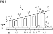
- a turbine 1 is shown, which is designed as an axial turbine 1 in the present exemplary embodiment.
- the turbine 1 is designed in four stages in the present exemplary embodiment, i.e. the turbine 1 has blading with four rotor blade rings 3a, 3b, 3c, 3d and three guide blade rings 4a, 4b, 4c, 4d.
- the rotor blade rings 3a, 3b, 3c, 3d each have a plurality of rotor blades 5, while the guide vane rings 4a, 4b, 4c, 4d each have a plurality of guide blades 6.
- the rotor blade rings 3a, 3b, 3c, 3d and the guide vane rings 4a, 4b, 4c, 4d are arranged alternately one behind the other in a housing 2 in the direction of flow of a working medium that flows through the turbine 1, starting with the guide vane ring 4a, followed by the rotor blade ring 3a etc.
- the housing 2 is conical and widens in the direction of flow S of the working medium.
- the blades 5 each have a blade 7, a platform 8 attached to the blade, a foot 9 attached to the platform 8 with a blade fastening section 10.
- the rotor blades 5 are fastened to a rotor shaft 11 of the turbine 1, in that they are inserted into respective groove-shaped receptacles 12 of the rotor shaft 11.
- the guide vanes 6 each have a guide vane leaf 3a, 3b, 3c, 3d and, at their radially outward ends, a guide vane fastening section 14, with which the guide vanes 6 are fastened to an annular guide vane carrier 15. At their radially inward ends, the guide vanes 6 each have a sealing element 16 which is arranged between rotor blade fastening sections 10 of two adjacent rotor blades 5. In order to improve a seal between the rotor blades 5 and guide blades 6, the rotor blade fastening sections 10 each have balconies 17, which are designed as extensions to the respective platform 8, which extend in or against the direction of flow.
- an original rotor blade ring 3a, 3b, 3c, 3d is removed at a first rotor blade position I.
- it is the last blade ring 3d in the flow direction S at the first blade position I.
- a replacement blade ring 3 ′ is then mounted at a second blade position II.
- the replacement blade ring 3 'at the second blade position II replaces the original blade ring 3d at the first blade position I.
- the replacement blade ring 3' consists of a plurality of replacement blades 5 '.
- the second rotor blade position II is arranged along a direction of extent of the rotor shaft 11 of the thermal turbomachine 1 in the flow direction of the working medium at a distance from the first rotor blade position I, the distance A being dimensioned such that the replacement rotor blade ring 3 'is still located within the housing 2 .
- the distance A is between 3 mm and 15 mm, e.g. 10 mm.
- the third rotor blade ring 3c, the fourth rotor blade ring 3d and the third guide vane ring 4c arranged between the third rotor blade ring 3c and fourth rotor blade ring 3d are displaced by the distance A in the direction of flow S.
- the replacement blade ring 3 ′ has a larger outer diameter than the original blade ring 3d, which is adapted to an inner diameter of the housing 2 at the second blade position II.
- a positioning element 18a is provided in order to fix the replacement rotor blade ring 3 ′ at the second rotor blade position II.
- the positioning element 18a is designed as a spacer disk or ring and has been pushed onto the rotor shaft 11 before the replacement blade ring 3 'is mounted.
- the positioning element 18b is integrally formed on the replacement blade ring 3 ', for example in the form of an extension 19 of the balcony 17.
- the positioning element 18b is formed by a rear contact surface 20, which is shortened 21 of the foot 9 is displaced forward counter to the direction of flow S. In other words, material is removed from the rear of the foot 8, so that the replacement blade ring 3 ′ can be displaced in the flow direction S due to the shortened foot 8.
- a turbine 1 can thus be modified with little effort.
Landscapes
- Engineering & Computer Science (AREA)
- Mechanical Engineering (AREA)
- General Engineering & Computer Science (AREA)
- Physics & Mathematics (AREA)
- Fluid Mechanics (AREA)
- Turbine Rotor Nozzle Sealing (AREA)
- Structures Of Non-Positive Displacement Pumps (AREA)
Description
- Die Erfindung betrifft ein Verfahren zum Modifizieren einer Turbine.
- Unter thermischen Strömungsmaschinen (auch Turbomaschinen genannt) werden dabei Maschinen verstanden, bei denen eine Energieübertragung zwischen einem Arbeitsmedium (Flüssigkeit oder Gas) und der thermische Strömungsmaschinen in einem offenen Raum durch eine Strömung nach den Gesetzen der Fluiddynamik über den Umweg der kinetischen Energie erfolgt.
- Eine derartige thermische Strömungsmaschine, wie z.B. eine Gasturbine, kann einen Verdichter und eine Turbine aufweisen. Der Verdichter ist zum Komprimieren von einem gasförmigen Arbeitsmedium ausgebildet, während die Turbine die innere Energie eines strömenden Arbeitsmediums in mechanische Energie umwandelt, die sie über eine Turbinenwelle abgibt.
- Thermische Strömungsmaschinen weisen eine Beschaufelung auf, die die Gesamtheit der Schaufeln z.B. der Turbine umfasst. Unterschieden wird dabei zwischen Lauf- und Leitschaufeln. Ein Kranz von Laufschaufeln mit dem zugehörigen Kranz von Leitschaufeln wird als Stufe bezeichnet. Die Beschaufelung der Turbine und/oder des Verdichters kann mehrstufig sein.
- Die Leitschaufeln sind fest in einem Gehäuse der Turbine eingebaut und leiten das Arbeitsmittel im optimalen Winkel auf die Laufschaufeln, die sich auf drehbaren Wellen befinden. Über die Laufschaufeln findet die Kopplung der mechanisch nutzbaren Leistung zwischen der thermischen Strömungsmaschine und dem Arbeitsmittel statt.
- Bei der Angabe der Stufenanzahl der Turbine ist die Anzahl der Laufschaufelkränze maßgebend: Eine z.B. fünfstufige Turbine hat fünf Laufschaufelkränze. Die Leitschaufelkränze werden bei Verdichtern meist dem vorausgehenden Laufschaufelkranz zugeordnet, bei Turbinen meist dem nachfolgenden Laufschaufelkranz.
- Schaufeln, d.h. Lauf- oder Leitschaufeln, weisen ein Schaufelblatt, eine an das Schaufelblatt angefügte Plattform, einen an die Plattform angefügten Fuß mit einem Befestigungsabschnitt zum Befestigen der Schaufel an dem Gehäuse bzw. an dem Rotor der Turbine auf.
- Jedoch ist eine Anpassung einer derartigen thermischen Strömungsmaschine an veränderte Anforderungen, insbesondere an gesteigerte Leistungsanforderungen, nur mit erheblichem Aufwand möglich. So ist es aus der
US 5,110,256 bekannt, zur Erhöhung der möglichen Maximalleistung sowohl die Laufschaufeln der letzten Dampfturbinenstufe als auch des zugehörigen Gehäuses zu ersetzen durch solche, die insgesamt eine größere Abströmfläche bereitstellen. Ein solcher Umbau ist jedoch vergleichsweise aufwändig, da beides nämlich Rotor und Gehäuse umgerüstet werden müssen. Eine weitere Umrüstung offenbart auch dieUS 5,494,405 . Anlass der Umrüstung ist hier das Auftreten von Feuchtigkeit in großem Umfang, so dass mit dem Umbau eine Möglichkeit zur einfacheren Abführung der Feuchtigkeit geschaffen wird. Hierzu sollen die Laufschaufeln der letzten Stufe einer Dampfturbine axial nach stromabwärts neu positioniert werden, um den dadurch gewonnenen Bauraum für vergrößerte Drainageöffnungen zu verwenden. - Es besteht daher Bedarf daran, zumindest einen Weg aufzuzeigen, wie eine Turbine mit geringem Aufwand modifiziert werden kann. Erfindungsgemäß wird dies durch ein Verfahren gemäß Anspruch 1 gelöst.
- Erfindungsgemäß wird zum Modifizieren einer Turbine mit in einem konisch ausgebildeten Gehäuse angeordneten Laufschaufelkränzen und Leitschaufelkränzen ein ursprünglicher Laufschaufelkranz an einer ersten Laufschaufelposition durch einen Austausch-Laufschaufelkranz an einer zweiten Laufschaufelposition ersetzt, wobei unter Beibehaltung des Gehäuses die zweite Laufschaufelposition entlang einer Erstreckungsrichtung einer Rotorwelle der Turbine in Strömungsrichtung eines die Turbine durchströmenden Arbeitsmediums beabstandet von der ersten Laufschaufelposition angeordnet ist. Hierdurch wird auf überraschend einfache Weise möglich, eine Turbine zu modifizieren, um sie an erhöhte Leistungsanforderungen anzupassen. Zugleich kann so die Machzahl des Arbeitsmediums reduziert werden.
- Weiter weist der Austausch-Laufschaufelkranz einen größeren Außendurchmesser als der ursprüngliche Laufschaufelkranz auf. Deren Verwendung erfolgt ohne eine Veränderung des Gehäuses, d.h. unter Beibehaltung des konischen Öffnungswinkels. Dies ist allein deswegen möglich, da aufgrund der Gehäuse-Konizität und der nunmehr weiter stromab angeordneten Laufschaufeln der Abstand zwischen Rotorachse und einem Innendurchmesser des Gehäuses vergrößert ist, verglichen mit dem Abstand an der ersten Laufschaufelposition. Somit erfolgt eine Anpassung an einen bereits vorhandenen vergrößerten Innendurchmesser des Gehäuses, so dass eine besonders energieeffiziente Turbine einfach bereitgestellt wird.
- Bevorzugt wird als Positionierelement ein separates Bauteil verwendet. So kann eine Festlegung der Position des Austausch-Laufschaufelkranzes ohne Modifikation der Rotorscheibe des Austausch-Laufschaufelkranzes erfolgen.
- Bevorzugt wird ein als Distanzscheibe oder Ring ausgebildetes Positionierelement in der Rotorwelle zur Festlegung des Austausch-Laufschaufelkranzes an der zweiten Laufschaufelposition angeordnet. So kann auf besonders einfache Weise der Austausch-Laufschaufelkranz an der zweiten Laufschaufelposition festgelegt werden, sodass bei den Austausch-Laufschaufeln die axialen Position des inneren Endes des Schaufelblatts im Bezug auf die axiale Position des Schaufelfußes unverändert beibehalten werden kann wie bei den ursprünglichen Laufschaufeln. Dies verringert die Konstruktionsaufwendungen zur Ermittlung der Gestalt der Austausch-Laufschaufeln.
- Bevorzugt wird ein als Distanzscheibe oder Ring ausgebildetes Positionierelement verwendet. So kann ein besonders einfach zu fertigendes Positionierelement verwendet werden.
- Bevorzugt wird das Positionierelement an dem Austausch-Laufschaufelkranz angeformt. Somit entfällt eine Montage zusätzlicher Bauteile.
- Bevorzugt wird das Positionierelement durch eine Verlängerung an einem Balkon eines Fußes einer Austausch-Laufschaufel des Austausch-Laufschaufelkranz gebildet. Im Detail werden die Schaufelfüße der Austausch-Laufschaufeln axial verändert, indem sie auf ihrer stromaufwärtigen Seite verlängert und auf ihrer stromabwärtigen Seite gekürzt werden. Die Rotorscheibe, in denen die Laufschaufeln in konventioneller Weise gehalten sind, kann demnach unverändert weiter verwendet werden, ohne dass in der Rotorwelle eine Distanzscheibe einlegen ist. Mithin sind die Austausch-Laufschaufeln sodann in der Nut der Rotorscheibe so angeordnet, dass deren Schaufelblatt axial weiter stromab angeordnet ist als es das Schaufelblatt der ursprünglichen Laufschaufeln war. Um einen vergrößerten Radialspalt an den Schaufelspitzen der Austausch-Laufschaufeln zu vermeiden, können deren Schaufelblätter spitzenseitig durch Auftragsschweißen oder andere geeignete additive Verfahren verlängert werden. So kann durch eine besonders einfache Abwandlung einer Laufschaufel das Positionierelement gebildet werden.
- Bevorzugt erfolgt zur Festlegung des Austausch-Laufschaufelkranz an der zweiten Laufschaufelposition eine Verkürzung (in axialer Richtung auf der Stromabseite) eines Fußes einer Austausch-Laufschaufel des Austausch-Laufschaufelkranz. So kann durch eine besonders einfache Abwandlung eines Fußes einer Laufschaufel die Position der Laufschaufel neu bestimmt werden, wenn beispielsweise sie an einem stromabwärts gelegenen Anschlag positioniert werden soll.
- Ferner gehören zur Erfindung eine derartig modifizierte Turbine und ein Laufschaufelkranz für eine derartige Turbine sowie eine Austausch-Laufschaufel für einen derartigen Austausch-Laufschaufelkranz.
- Im Folgenden wird eine bevorzugte Ausführungsform des erfindungsgemäßen Verfahrens anhand der beigefügten schematischen Zeichnungen erläutert. Es zeigt:
-
Fig. 1 eine schematische Darstellung eines Abschnitts einer Turbine. -
Fig. 2 eine schematischer Darstellung einer Modifikation der inFig. 1 gezeigten Turbine. -
Fig. 3 ein Detail der modifizierten Turbine. - Es wird zunächst auf
Fig. 1 Bezug genommen. - Dargestellt ist eine Turbine 1, die im vorliegenden Ausführungsbeispiel als Axialturbine 1 ausgebildet ist.
- Die Turbine 1 ist im vorliegenden Ausführungsbeispiel vierstufig ausgebildet, d.h. die Turbine 1 weist eine Beschaufelung mit vier Laufschaufelkränzen 3a, 3b, 3c, 3d und drei Leitschaufelkränzen 4a, 4b, 4c, 4d auf.
- Die Laufschaufelkränze 3a, 3b, 3c, 3d weisen jeweils eine Mehrzahl von Laufschaufeln 5 auf, während die Leitschaufelkränze 4a, 4b, 4c, 4d jeweils eine Mehrzahl von Leitschaufeln 6 aufweisen.
- Die Laufschaufelkränze 3a, 3b, 3c, 3d und die Leitschaufelkränze 4a, 4b, 4c, 4d sind abwechselnd hintereinander in einem Gehäuse 2 in Strömungsrichtung eines Arbeitsmediums angeordnet, das die Turbine 1 durchströmt, beginnend mit dem Leitschaufelkranz 4a, gefolgt von dem Laufschaufelkranz 3a usw. Dabei ist das Gehäuse 2 konisch ausgebildet und weitet sich in Strömungsrichtung S des Arbeitsmediums auf.
- Die Laufschaufeln 5 weisen jeweils ein Laufschaufelblatt 7, eine an das Schaufelblatt angefügte Plattform 8, einen an die Plattform 8 angefügten Fuß 9 mit einem Laufschaufel- Befestigungsabschnitt 10 auf.
- Mit den jeweiligen Laufschaufel-Befestigungsabschnitten 10 sind die Laufschaufeln 5 an einer Rotorwelle 11 der Turbine 1 befestigt, in dem sie in jeweilige nutförmige Aufnahmen 12 der Rotorwelle 11 eingesetzt sind.
- Die Leitschaufeln 6 weisen jeweils ein Leitschaufelblatt 3a, 3b, 3c, 3d und an ihren radial auswärtigen Enden einen Leitschaufel-Befestigungsabschnitt 14 auf, mit denen die Leitschaufeln 6 an einem ringförmigen Leitschaufelträger 15 befestigt sind. An ihren radial einwärtigen Enden weisen die Leitschaufeln 6 jeweils ein Dichtungselement 16 auf, das jeweils zwischen Laufschaufel-Befestigungsabschnitte 10 zweier benachbarter Laufschaufeln 5 angeordnet sind. Um eine Abdichtung zwischen den Laufschaufeln 5 und Leitschaufeln 6 zu verbessern weisen die Laufschaufel-Befestigungsabschnitte 10 jeweils Balkone 17 auf, die als Verlängerung an die jeweilige Plattform 8 ausgebildet sind, die sich in oder entgegen der Strömungsrichtung erstrecken.
- Es wird nun zusätzlich auf
Fig. 2 Bezug genommen, um ein Ausführungsbeispiel eines Verfahrens zum Modifizieren der Turbine 1 zu erläutern. - Um die Turbine 1 zu modifizieren, z.B. um sie an erhöhte Leistungsanforderungen anzupassen, wird ein ursprünglicher Laufschaufelkranz 3a, 3b, 3c, 3d an einer ersten Laufschaufelposition I entfernt. Im vorliegenden Ausführungsbeispiel handelt es sich um den in Strömungsrichtung S letzten Laufschaufelkranz 3d an der ersten Laufschaufelposition I.
- Es wird dann ein Austausch-Laufschaufelkranz 3'an einer zweiten Laufschaufelposition II montiert. Mit anderen Worten, der Austausch-Laufschaufelkranz 3' an der zweiten Laufschaufelposition II ersetzt den ursprünglichen Laufschaufelkranz 3d an der ersten Laufschaufelposition I. Dabei besteht der Austausch-Laufschaufelkranz 3' aus einer Mehrzahl an Austausch-Laufschaufeln 5'.
- Dabei ist die zweite Laufschaufelposition II entlang einer Erstreckungsrichtung der Rotorwelle 11 der thermischen Strömungsmaschine 1 in Strömungsrichtung des Arbeitsmediums beabstandet von der ersten Laufschaufelposition I angeordnet, wobei der Abstand A derart bemessen ist, dass der Austausch-Laufschaufelkranz 3' sich noch innerhalb des Gehäuses 2 befindet. Der Abstand A beträgt im vorliegenden Ausführungsbeispiel zwischen 3 mm bis 15 mm, z.B. 10 mm.
- Abweichend vom vorliegenden Ausführungsbeispiel kann auch vorgesehen sein, z.B. den zweiten Laufschaufelkranz 3b um den Abstand A zu verlagern. In diesem Fall werden der dritte Laufschaufelkranz 3c, der vierte Laufschaufelkranz 3d sowie der zwischen dem dritten Laufschaufelkranz 3c und vierten Laufschaufelkranz 3d angeordnete dritte Leitschaufelkranz 4c um den Abstand A in Strömungsrichtung S verlagert.
- Der Austausch-Laufschaufelkranz 3' weist einen größeren Außendurchmesser als der ursprüngliche Laufschaufelkranz 3d auf, der an einen Innendurchmesser des Gehäuses 2 an der zweiten Laufschaufelposition II angepasst ist.
- Um den Austausch-Laufschaufelkranz 3' an der zweiten Laufschaufelposition II festzulegen ist ein Positionierelement 18a vorgesehen. Das Positionierelement 18a ist im vorliegenden Ausführungsführungsbeispiel als Distanzscheibe oder Ring ausgebildet und auf die Rotorwelle 11 aufgeschoben worden, bevor der Austausch-Laufschaufelkranz 3' montiert wird.
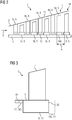
- Es wird nun unter Bezugnahme auf
Fig. 3 ein zweites Ausführungsbeispiel des Positionierelements 18b erläutert. - Das Positionierelement 18b ist gemäß dem zweiten Ausführungsbeispiel an dem Austausch-Laufschaufelkranz 3' angeformt, z.B. in Form einer Verlängerung 19 des Balkons 17. Alternativ oder zusätzlich kann vorgesehen sein, dass das Positionierelement 18b durch eine rückwärtige Kontaktfläche 20 gebildet ist, die durch eine Verkürzung 21 des Fußes 9 entgegen der Strömungsrichtung S nach vorne verlagert ist. Mit anderen Worten, an der Rückseite des Fußes 8 wird Material abgetragen, sodass aufgrund des verkürzten Fußes 8 der Austausch-Laufschaufelkranz 3' in Strömungsrichtung S verlagert werden kann.
- So kann mit geringem Aufwand eine Turbine 1 modifiziert werden.
- Obwohl die Erfindung im Detail durch das bevorzugte Ausführungsbeispiel näher illustriert und beschrieben wurde, so ist die Erfindung nicht durch die offenbarten Beispiele eingeschränkt und andere Variationen können vom Fachmann hieraus abgeleitet werden, ohne den Schutzumfang der Erfindung zu verlassen.
Claims (6)
- Verfahren zum Modifizieren einer Turbine (1) mit in einem konisch ausgebildeten Gehäuse (2) angeordneten Laufschaufelkränzen (3a, 3b, 3c, 3d) und Leitschaufelkränzen (4a, 4b, 4c, 4d), bei dem ein ursprünglicher Laufschaufelkranz (3a, 3b, 3c, 3d) an einer ersten Laufschaufelposition (I) durch einen Austausch-Laufschaufelkranz (3') an einer zweiten Laufschaufelposition (II) ersetzt wird,
wobei unter Beibehaltung des Gehäuses (2) die zweite Laufschaufelpcsition (II) entlang einer Erstreckungsrichtung einer Rotorwelle der Turbine (1) in Strömungsrichtung (S) eines die Turbine (1) durchströmenden Arbeitsmediums beabstandet von der ersten Laufschaufelposition (I) angeordnet wird,
wobei der Austausch-Laufschaufelkranz (3') einen größeren Außendurchmesser als der ursprüngliche Laufschaufelkranz (3a, 3b, 3c, 3d) aufweist. - Verfahren nach Anspruch 1, wobei ein Positionierelement (18a) zur Festlegung des Austausch-Laufschaufelkranz an der zweiten Laufschaufelposition (II) verwendet wird und das Positionierelement ein separates Bauteil ist.
- Verfahren nach Anspruch 1 bei dem ein als Distanzscheibe oder Ring ausgebildetes Positionierelement (18a, 18b) auf der Rotorwelle (11) zur Festlegung des Austausch-Laufschaufelkranzes (3') an der zweiten Laufschaufelposition (II) angeordnet wird.
- Verfahren nach Anspruch 1,
wobei ein Positionierelement (18b) an dem Austausch-Laufschaufelkranz (3') angeformt wird - Verfahren nach Anspruch 4,
wobei das Positionierelement (18b) durch eine Verlängerung (19) an einem Balkon (17) eines Fußes (8) einer Austausch-Laufschaufel (5') des Austausch-Laufschaufelkranz (3') gebildet wird. - Verfahren nach einem der Ansprüche 4 oder 5,
wobei zur Festlegung des Austausch-Laufschaufelkranz (3') an der zweiten Laufschaufelposition (II) eine Verkürzung (21) eines Fußes (9) einer Austausch-Laufschaufel (5') des Austausch-Laufschaufelkranzes (3') erfolgt.
Applications Claiming Priority (2)
| Application Number | Priority Date | Filing Date | Title |
|---|---|---|---|
| EP17155610.3A EP3361049A1 (de) | 2017-02-10 | 2017-02-10 | Verfahren zum modifizieren einer turbine |
| PCT/EP2018/052803 WO2018146046A1 (de) | 2017-02-10 | 2018-02-05 | Verfahren zum modifizieren einer turbine |
Publications (2)
| Publication Number | Publication Date |
|---|---|
| EP3551850A1 EP3551850A1 (de) | 2019-10-16 |
| EP3551850B1 true EP3551850B1 (de) | 2021-03-31 |
Family
ID=58016621
Family Applications (2)
| Application Number | Title | Priority Date | Filing Date |
|---|---|---|---|
| EP17155610.3A Withdrawn EP3361049A1 (de) | 2017-02-10 | 2017-02-10 | Verfahren zum modifizieren einer turbine |
| EP18704502.6A Active EP3551850B1 (de) | 2017-02-10 | 2018-02-05 | Verfahren zum modifizieren einer turbine |
Family Applications Before (1)
| Application Number | Title | Priority Date | Filing Date |
|---|---|---|---|
| EP17155610.3A Withdrawn EP3361049A1 (de) | 2017-02-10 | 2017-02-10 | Verfahren zum modifizieren einer turbine |
Country Status (5)
| Country | Link |
|---|---|
| US (1) | US20200011182A1 (de) |
| EP (2) | EP3361049A1 (de) |
| KR (1) | KR20190108637A (de) |
| CN (1) | CN110268135A (de) |
| WO (1) | WO2018146046A1 (de) |
Families Citing this family (1)
| Publication number | Priority date | Publication date | Assignee | Title |
|---|---|---|---|---|
| JP7261697B2 (ja) * | 2018-09-06 | 2023-04-20 | エトスエナジー・イタリア・ソシエタ・ペル・アチオニ | ガスタービンの多段式軸流圧縮機のロータを修復する方法 |
Family Cites Families (7)
| Publication number | Priority date | Publication date | Assignee | Title |
|---|---|---|---|---|
| US4900230A (en) * | 1989-04-27 | 1990-02-13 | Westinghouse Electric Corp. | Low pressure end blade for a low pressure steam turbine |
| US5110256A (en) * | 1991-02-11 | 1992-05-05 | Westinghouse Electric Corp. | Methods and apparatus for attaching a flow guide to a steam turbine for retrofit of longer rotational blades |
| US5494405A (en) * | 1995-03-20 | 1996-02-27 | Westinghouse Electric Corporation | Method of modifying a steam turbine |
| JP2003269109A (ja) * | 2002-03-18 | 2003-09-25 | Toshiba Corp | 蒸気タービン |
| US9234435B2 (en) * | 2013-03-11 | 2016-01-12 | Pratt & Whitney Canada Corp. | Tip-controlled integrally bladed rotor for gas turbine |
| US20160186593A1 (en) * | 2014-12-31 | 2016-06-30 | General Electric Company | Flowpath boundary and rotor assemblies in gas turbines |
| CN105332948B (zh) * | 2015-10-23 | 2017-08-15 | 上海交通大学 | 一种压气机仿生动叶的实现方法 |
-
2017
- 2017-02-10 EP EP17155610.3A patent/EP3361049A1/de not_active Withdrawn
-
2018
- 2018-02-05 KR KR1020197026067A patent/KR20190108637A/ko not_active Abandoned
- 2018-02-05 CN CN201880011189.0A patent/CN110268135A/zh active Pending
- 2018-02-05 WO PCT/EP2018/052803 patent/WO2018146046A1/de not_active Ceased
- 2018-02-05 EP EP18704502.6A patent/EP3551850B1/de active Active
- 2018-02-05 US US16/483,425 patent/US20200011182A1/en not_active Abandoned
Non-Patent Citations (1)
| Title |
|---|
| None * |
Also Published As
| Publication number | Publication date |
|---|---|
| CN110268135A (zh) | 2019-09-20 |
| US20200011182A1 (en) | 2020-01-09 |
| EP3361049A1 (de) | 2018-08-15 |
| EP3551850A1 (de) | 2019-10-16 |
| KR20190108637A (ko) | 2019-09-24 |
| WO2018146046A1 (de) | 2018-08-16 |
Similar Documents
| Publication | Publication Date | Title |
|---|---|---|
| DE69203705T2 (de) | Stator zur Einführung von Luft in das Innere einer Turbomaschine und Verfahren zum Montieren einer Schaufel dieses Stators. | |
| EP3287611B1 (de) | Gasturbine | |
| DE102015201782A1 (de) | Leitschaufelring für eine Strömungsmaschine | |
| EP2918778B1 (de) | Verfahren zum auslegen einer turbine | |
| EP3467261B1 (de) | Verfahren zum herstellen eines tandem-leitschaufelsegments | |
| EP2478186B1 (de) | Rotor einer Turbomaschine | |
| DE102015224283A1 (de) | Leitschaufelcluster für eine Strömungsmaschine | |
| EP2818724B1 (de) | Strömungsmaschine und Verfahren | |
| EP2799776A1 (de) | Brennerdichtung für Gasturbinen-Brennkammerkopf und Hitzeschild | |
| WO2011124214A2 (de) | Leitschaufel einer strömungsmaschine | |
| DE102007050916A1 (de) | Verfahren und Vorrichtung zum Zusammenbau von Gasturbinen-Triebwerken | |
| EP2918776B1 (de) | Verfahren zur herstellung eines doppelreihigen schaufelrads für eine strömungsmaschine und doppelreihiges schaufelrad | |
| EP2647796A1 (de) | Dichtungssystem für eine Strömungsmaschine | |
| EP3492701A1 (de) | Turbomaschinen-strömungskanal | |
| EP2787178B1 (de) | Leitschaufelanordnung | |
| EP2526263B1 (de) | Gehäusesystem für eine axialströmungsmaschine | |
| DE102009007664A1 (de) | Abdichtvorrichtung an dem Schaufelschaft einer Rotorstufe einer axialen Strömungsmaschine | |
| EP3551850B1 (de) | Verfahren zum modifizieren einer turbine | |
| EP3561228A1 (de) | Schaufel, schaufelsegment und baugruppe für eine turbomaschine und turbomaschine | |
| DE102019108267A1 (de) | Vorrichtung zur Befestigung von Dichtplatten zwischen Bauteilen eines Gasturbinentriebwerks | |
| EP3312388B1 (de) | Rotorteil, zugehörigeverdichter, turbine und herstellungsverfahren | |
| EP3056684B1 (de) | Axial geteilter Innenring für eine Strömungsmaschine, Leitschaufelkranz und Flugtriebwerk | |
| EP3428391B1 (de) | Turbomaschinen-schaufelgitter | |
| DE102019220028B4 (de) | Axialturbine | |
| EP3536913A1 (de) | Innenring für eine turbomaschine und entsprechendes herstellungsverfahren |
Legal Events
| Date | Code | Title | Description |
|---|---|---|---|
| STAA | Information on the status of an ep patent application or granted ep patent |
Free format text: STATUS: UNKNOWN |
|
| STAA | Information on the status of an ep patent application or granted ep patent |
Free format text: STATUS: THE INTERNATIONAL PUBLICATION HAS BEEN MADE |
|
| PUAI | Public reference made under article 153(3) epc to a published international application that has entered the european phase |
Free format text: ORIGINAL CODE: 0009012 |
|
| STAA | Information on the status of an ep patent application or granted ep patent |
Free format text: STATUS: REQUEST FOR EXAMINATION WAS MADE |
|
| 17P | Request for examination filed |
Effective date: 20190710 |
|
| AK | Designated contracting states |
Kind code of ref document: A1 Designated state(s): AL AT BE BG CH CY CZ DE DK EE ES FI FR GB GR HR HU IE IS IT LI LT LU LV MC MK MT NL NO PL PT RO RS SE SI SK SM TR |
|
| AX | Request for extension of the european patent |
Extension state: BA ME |
|
| DAV | Request for validation of the european patent (deleted) | ||
| DAX | Request for extension of the european patent (deleted) | ||
| GRAP | Despatch of communication of intention to grant a patent |
Free format text: ORIGINAL CODE: EPIDOSNIGR1 |
|
| STAA | Information on the status of an ep patent application or granted ep patent |
Free format text: STATUS: GRANT OF PATENT IS INTENDED |
|
| INTG | Intention to grant announced |
Effective date: 20201117 |
|
| RAP1 | Party data changed (applicant data changed or rights of an application transferred) |
Owner name: SIEMENS ENERGY GLOBAL GMBH & CO. KG |
|
| GRAS | Grant fee paid |
Free format text: ORIGINAL CODE: EPIDOSNIGR3 |
|
| GRAA | (expected) grant |
Free format text: ORIGINAL CODE: 0009210 |
|
| STAA | Information on the status of an ep patent application or granted ep patent |
Free format text: STATUS: THE PATENT HAS BEEN GRANTED |
|
| AK | Designated contracting states |
Kind code of ref document: B1 Designated state(s): AL AT BE BG CH CY CZ DE DK EE ES FI FR GB GR HR HU IE IS IT LI LT LU LV MC MK MT NL NO PL PT RO RS SE SI SK SM TR |
|
| REG | Reference to a national code |
Ref country code: GB Ref legal event code: FG4D Free format text: NOT ENGLISH Ref country code: CH Ref legal event code: EP |
|
| REG | Reference to a national code |
Ref country code: AT Ref legal event code: REF Ref document number: 1377126 Country of ref document: AT Kind code of ref document: T Effective date: 20210415 |
|
| REG | Reference to a national code |
Ref country code: DE Ref legal event code: R096 Ref document number: 502018004527 Country of ref document: DE |
|
| REG | Reference to a national code |
Ref country code: IE Ref legal event code: FG4D Free format text: LANGUAGE OF EP DOCUMENT: GERMAN |
|
| REG | Reference to a national code |
Ref country code: LT Ref legal event code: MG9D |
|
| PG25 | Lapsed in a contracting state [announced via postgrant information from national office to epo] |
Ref country code: HR Free format text: LAPSE BECAUSE OF FAILURE TO SUBMIT A TRANSLATION OF THE DESCRIPTION OR TO PAY THE FEE WITHIN THE PRESCRIBED TIME-LIMIT Effective date: 20210331 Ref country code: FI Free format text: LAPSE BECAUSE OF FAILURE TO SUBMIT A TRANSLATION OF THE DESCRIPTION OR TO PAY THE FEE WITHIN THE PRESCRIBED TIME-LIMIT Effective date: 20210331 Ref country code: BG Free format text: LAPSE BECAUSE OF FAILURE TO SUBMIT A TRANSLATION OF THE DESCRIPTION OR TO PAY THE FEE WITHIN THE PRESCRIBED TIME-LIMIT Effective date: 20210630 Ref country code: NO Free format text: LAPSE BECAUSE OF FAILURE TO SUBMIT A TRANSLATION OF THE DESCRIPTION OR TO PAY THE FEE WITHIN THE PRESCRIBED TIME-LIMIT Effective date: 20210630 |
|
| PG25 | Lapsed in a contracting state [announced via postgrant information from national office to epo] |
Ref country code: LV Free format text: LAPSE BECAUSE OF FAILURE TO SUBMIT A TRANSLATION OF THE DESCRIPTION OR TO PAY THE FEE WITHIN THE PRESCRIBED TIME-LIMIT Effective date: 20210331 Ref country code: RS Free format text: LAPSE BECAUSE OF FAILURE TO SUBMIT A TRANSLATION OF THE DESCRIPTION OR TO PAY THE FEE WITHIN THE PRESCRIBED TIME-LIMIT Effective date: 20210331 Ref country code: SE Free format text: LAPSE BECAUSE OF FAILURE TO SUBMIT A TRANSLATION OF THE DESCRIPTION OR TO PAY THE FEE WITHIN THE PRESCRIBED TIME-LIMIT Effective date: 20210331 |
|
| REG | Reference to a national code |
Ref country code: NL Ref legal event code: MP Effective date: 20210331 |
|
| PG25 | Lapsed in a contracting state [announced via postgrant information from national office to epo] |
Ref country code: CZ Free format text: LAPSE BECAUSE OF FAILURE TO SUBMIT A TRANSLATION OF THE DESCRIPTION OR TO PAY THE FEE WITHIN THE PRESCRIBED TIME-LIMIT Effective date: 20210331 Ref country code: EE Free format text: LAPSE BECAUSE OF FAILURE TO SUBMIT A TRANSLATION OF THE DESCRIPTION OR TO PAY THE FEE WITHIN THE PRESCRIBED TIME-LIMIT Effective date: 20210331 Ref country code: LT Free format text: LAPSE BECAUSE OF FAILURE TO SUBMIT A TRANSLATION OF THE DESCRIPTION OR TO PAY THE FEE WITHIN THE PRESCRIBED TIME-LIMIT Effective date: 20210331 Ref country code: NL Free format text: LAPSE BECAUSE OF FAILURE TO SUBMIT A TRANSLATION OF THE DESCRIPTION OR TO PAY THE FEE WITHIN THE PRESCRIBED TIME-LIMIT Effective date: 20210331 Ref country code: SM Free format text: LAPSE BECAUSE OF FAILURE TO SUBMIT A TRANSLATION OF THE DESCRIPTION OR TO PAY THE FEE WITHIN THE PRESCRIBED TIME-LIMIT Effective date: 20210331 |
|
| PG25 | Lapsed in a contracting state [announced via postgrant information from national office to epo] |
Ref country code: IS Free format text: LAPSE BECAUSE OF FAILURE TO SUBMIT A TRANSLATION OF THE DESCRIPTION OR TO PAY THE FEE WITHIN THE PRESCRIBED TIME-LIMIT Effective date: 20210731 Ref country code: PT Free format text: LAPSE BECAUSE OF FAILURE TO SUBMIT A TRANSLATION OF THE DESCRIPTION OR TO PAY THE FEE WITHIN THE PRESCRIBED TIME-LIMIT Effective date: 20210802 Ref country code: PL Free format text: LAPSE BECAUSE OF FAILURE TO SUBMIT A TRANSLATION OF THE DESCRIPTION OR TO PAY THE FEE WITHIN THE PRESCRIBED TIME-LIMIT Effective date: 20210331 Ref country code: RO Free format text: LAPSE BECAUSE OF FAILURE TO SUBMIT A TRANSLATION OF THE DESCRIPTION OR TO PAY THE FEE WITHIN THE PRESCRIBED TIME-LIMIT Effective date: 20210331 Ref country code: SK Free format text: LAPSE BECAUSE OF FAILURE TO SUBMIT A TRANSLATION OF THE DESCRIPTION OR TO PAY THE FEE WITHIN THE PRESCRIBED TIME-LIMIT Effective date: 20210331 |
|
| REG | Reference to a national code |
Ref country code: DE Ref legal event code: R097 Ref document number: 502018004527 Country of ref document: DE |
|
| PG25 | Lapsed in a contracting state [announced via postgrant information from national office to epo] |
Ref country code: ES Free format text: LAPSE BECAUSE OF FAILURE TO SUBMIT A TRANSLATION OF THE DESCRIPTION OR TO PAY THE FEE WITHIN THE PRESCRIBED TIME-LIMIT Effective date: 20210331 Ref country code: DK Free format text: LAPSE BECAUSE OF FAILURE TO SUBMIT A TRANSLATION OF THE DESCRIPTION OR TO PAY THE FEE WITHIN THE PRESCRIBED TIME-LIMIT Effective date: 20210331 Ref country code: AL Free format text: LAPSE BECAUSE OF FAILURE TO SUBMIT A TRANSLATION OF THE DESCRIPTION OR TO PAY THE FEE WITHIN THE PRESCRIBED TIME-LIMIT Effective date: 20210331 |
|
| PLBE | No opposition filed within time limit |
Free format text: ORIGINAL CODE: 0009261 |
|
| STAA | Information on the status of an ep patent application or granted ep patent |
Free format text: STATUS: NO OPPOSITION FILED WITHIN TIME LIMIT |
|
| 26N | No opposition filed |
Effective date: 20220104 |
|
| PG25 | Lapsed in a contracting state [announced via postgrant information from national office to epo] |
Ref country code: IS Free format text: LAPSE BECAUSE OF FAILURE TO SUBMIT A TRANSLATION OF THE DESCRIPTION OR TO PAY THE FEE WITHIN THE PRESCRIBED TIME-LIMIT Effective date: 20210731 |
|
| REG | Reference to a national code |
Ref country code: DE Ref legal event code: R119 Ref document number: 502018004527 Country of ref document: DE |
|
| PG25 | Lapsed in a contracting state [announced via postgrant information from national office to epo] |
Ref country code: MC Free format text: LAPSE BECAUSE OF FAILURE TO SUBMIT A TRANSLATION OF THE DESCRIPTION OR TO PAY THE FEE WITHIN THE PRESCRIBED TIME-LIMIT Effective date: 20210331 |
|
| REG | Reference to a national code |
Ref country code: CH Ref legal event code: PL |
|
| REG | Reference to a national code |
Ref country code: BE Ref legal event code: MM Effective date: 20220228 |
|
| GBPC | Gb: european patent ceased through non-payment of renewal fee |
Effective date: 20220205 |
|
| PG25 | Lapsed in a contracting state [announced via postgrant information from national office to epo] |
Ref country code: LU Free format text: LAPSE BECAUSE OF NON-PAYMENT OF DUE FEES Effective date: 20220205 |
|
| PG25 | Lapsed in a contracting state [announced via postgrant information from national office to epo] |
Ref country code: FR Free format text: LAPSE BECAUSE OF NON-PAYMENT OF DUE FEES Effective date: 20220228 |
|
| PG25 | Lapsed in a contracting state [announced via postgrant information from national office to epo] |
Ref country code: LI Free format text: LAPSE BECAUSE OF NON-PAYMENT OF DUE FEES Effective date: 20220228 Ref country code: IE Free format text: LAPSE BECAUSE OF NON-PAYMENT OF DUE FEES Effective date: 20220205 Ref country code: GB Free format text: LAPSE BECAUSE OF NON-PAYMENT OF DUE FEES Effective date: 20220205 Ref country code: DE Free format text: LAPSE BECAUSE OF NON-PAYMENT OF DUE FEES Effective date: 20220901 Ref country code: CH Free format text: LAPSE BECAUSE OF NON-PAYMENT OF DUE FEES Effective date: 20220228 |
|
| PG25 | Lapsed in a contracting state [announced via postgrant information from national office to epo] |
Ref country code: BE Free format text: LAPSE BECAUSE OF NON-PAYMENT OF DUE FEES Effective date: 20220228 |
|
| REG | Reference to a national code |
Ref country code: AT Ref legal event code: MM01 Ref document number: 1377126 Country of ref document: AT Kind code of ref document: T Effective date: 20230205 |
|
| PG25 | Lapsed in a contracting state [announced via postgrant information from national office to epo] |
Ref country code: AT Free format text: LAPSE BECAUSE OF NON-PAYMENT OF DUE FEES Effective date: 20230205 |
|
| PG25 | Lapsed in a contracting state [announced via postgrant information from national office to epo] |
Ref country code: MK Free format text: LAPSE BECAUSE OF FAILURE TO SUBMIT A TRANSLATION OF THE DESCRIPTION OR TO PAY THE FEE WITHIN THE PRESCRIBED TIME-LIMIT Effective date: 20210331 Ref country code: CY Free format text: LAPSE BECAUSE OF FAILURE TO SUBMIT A TRANSLATION OF THE DESCRIPTION OR TO PAY THE FEE WITHIN THE PRESCRIBED TIME-LIMIT Effective date: 20210331 Ref country code: AT Free format text: LAPSE BECAUSE OF NON-PAYMENT OF DUE FEES Effective date: 20230205 |
|
| PG25 | Lapsed in a contracting state [announced via postgrant information from national office to epo] |
Ref country code: HU Free format text: LAPSE BECAUSE OF FAILURE TO SUBMIT A TRANSLATION OF THE DESCRIPTION OR TO PAY THE FEE WITHIN THE PRESCRIBED TIME-LIMIT; INVALID AB INITIO Effective date: 20180205 |
|
| PG25 | Lapsed in a contracting state [announced via postgrant information from national office to epo] |
Ref country code: MT Free format text: LAPSE BECAUSE OF FAILURE TO SUBMIT A TRANSLATION OF THE DESCRIPTION OR TO PAY THE FEE WITHIN THE PRESCRIBED TIME-LIMIT Effective date: 20210331 |
|
| PG25 | Lapsed in a contracting state [announced via postgrant information from national office to epo] |
Ref country code: GR Free format text: LAPSE BECAUSE OF NON-PAYMENT OF DUE FEES Effective date: 20210331 |
|
| PG25 | Lapsed in a contracting state [announced via postgrant information from national office to epo] |
Ref country code: GR Free format text: LAPSE BECAUSE OF NON-PAYMENT OF DUE FEES Effective date: 20210331 |
|
| PG25 | Lapsed in a contracting state [announced via postgrant information from national office to epo] |
Ref country code: TR Free format text: LAPSE BECAUSE OF FAILURE TO SUBMIT A TRANSLATION OF THE DESCRIPTION OR TO PAY THE FEE WITHIN THE PRESCRIBED TIME-LIMIT Effective date: 20210331 |
|
| PGFP | Annual fee paid to national office [announced via postgrant information from national office to epo] |
Ref country code: AT Payment date: 20260410 Year of fee payment: 5 |
|
| PGFP | Annual fee paid to national office [announced via postgrant information from national office to epo] |
Ref country code: IT Payment date: 20260220 Year of fee payment: 9 |