EP3551850B1 - Procédé de modification d'une turbine - Google Patents
Procédé de modification d'une turbine Download PDFInfo
- Publication number
- EP3551850B1 EP3551850B1 EP18704502.6A EP18704502A EP3551850B1 EP 3551850 B1 EP3551850 B1 EP 3551850B1 EP 18704502 A EP18704502 A EP 18704502A EP 3551850 B1 EP3551850 B1 EP 3551850B1
- Authority
- EP
- European Patent Office
- Prior art keywords
- rotor blade
- replacement
- turbine
- ring
- rotor
- Prior art date
- Legal status (The legal status is an assumption and is not a legal conclusion. Google has not performed a legal analysis and makes no representation as to the accuracy of the status listed.)
- Active
Links
Images
Classifications
-
- F—MECHANICAL ENGINEERING; LIGHTING; HEATING; WEAPONS; BLASTING
- F01—MACHINES OR ENGINES IN GENERAL; ENGINE PLANTS IN GENERAL; STEAM ENGINES
- F01D—NON-POSITIVE DISPLACEMENT MACHINES OR ENGINES, e.g. STEAM TURBINES
- F01D5/00—Blades; Blade-carrying members; Heating, heat-insulating, cooling or antivibration means on the blades or the members
- F01D5/02—Blade-carrying members, e.g. rotors
- F01D5/025—Fixing blade carrying members on shafts
-
- B—PERFORMING OPERATIONS; TRANSPORTING
- B23—MACHINE TOOLS; METAL-WORKING NOT OTHERWISE PROVIDED FOR
- B23P—METAL-WORKING NOT OTHERWISE PROVIDED FOR; COMBINED OPERATIONS; UNIVERSAL MACHINE TOOLS
- B23P6/00—Restoring or reconditioning objects
- B23P6/002—Repairing turbine components, e.g. moving or stationary blades, rotors
-
- F—MECHANICAL ENGINEERING; LIGHTING; HEATING; WEAPONS; BLASTING
- F01—MACHINES OR ENGINES IN GENERAL; ENGINE PLANTS IN GENERAL; STEAM ENGINES
- F01D—NON-POSITIVE DISPLACEMENT MACHINES OR ENGINES, e.g. STEAM TURBINES
- F01D5/00—Blades; Blade-carrying members; Heating, heat-insulating, cooling or antivibration means on the blades or the members
- F01D5/12—Blades
- F01D5/14—Form or construction
- F01D5/141—Shape, i.e. outer, aerodynamic form
- F01D5/142—Shape, i.e. outer, aerodynamic form of the blades of successive rotor or stator blade-rows
- F01D5/143—Contour of the outer or inner working fluid flow path wall, i.e. shroud or hub contour
-
- F—MECHANICAL ENGINEERING; LIGHTING; HEATING; WEAPONS; BLASTING
- F05—INDEXING SCHEMES RELATING TO ENGINES OR PUMPS IN VARIOUS SUBCLASSES OF CLASSES F01-F04
- F05D—INDEXING SCHEME FOR ASPECTS RELATING TO NON-POSITIVE-DISPLACEMENT MACHINES OR ENGINES, GAS-TURBINES OR JET-PROPULSION PLANTS
- F05D2230/00—Manufacture
- F05D2230/60—Assembly methods
- F05D2230/64—Assembly methods using positioning or alignment devices for aligning or centring, e.g. pins
-
- F—MECHANICAL ENGINEERING; LIGHTING; HEATING; WEAPONS; BLASTING
- F05—INDEXING SCHEMES RELATING TO ENGINES OR PUMPS IN VARIOUS SUBCLASSES OF CLASSES F01-F04
- F05D—INDEXING SCHEME FOR ASPECTS RELATING TO NON-POSITIVE-DISPLACEMENT MACHINES OR ENGINES, GAS-TURBINES OR JET-PROPULSION PLANTS
- F05D2230/00—Manufacture
- F05D2230/80—Repairing, retrofitting or upgrading methods
-
- F—MECHANICAL ENGINEERING; LIGHTING; HEATING; WEAPONS; BLASTING
- F05—INDEXING SCHEMES RELATING TO ENGINES OR PUMPS IN VARIOUS SUBCLASSES OF CLASSES F01-F04
- F05D—INDEXING SCHEME FOR ASPECTS RELATING TO NON-POSITIVE-DISPLACEMENT MACHINES OR ENGINES, GAS-TURBINES OR JET-PROPULSION PLANTS
- F05D2270/00—Control
- F05D2270/01—Purpose of the control system
- F05D2270/20—Purpose of the control system to optimize the performance of a machine
Definitions
- the invention relates to a method for modifying a turbine.
- Thermal flow machines also called turbo machines are understood to mean machines in which energy is transferred between a working medium (liquid or gas) and the thermal flow machine in an open space through a flow according to the laws of fluid dynamics via the detour of kinetic energy.
- Such a thermal fluid machine such as a gas turbine
- a compressor can have a compressor and a turbine.
- the compressor is designed to compress a gaseous working medium, while the turbine converts the internal energy of a flowing working medium into mechanical energy, which it emits via a turbine shaft.
- Thermal turbomachines have blading that includes the entirety of the blades, e.g. the turbine. A distinction is made between rotor blades and guide blades. A ring of rotor blades with the associated ring of guide blades is referred to as a step.
- the blading of the turbine and / or the compressor can be multi-stage.
- the guide vanes are permanently installed in a housing of the turbine and guide the working fluid at the optimum angle onto the rotor blades, which are located on rotating shafts.
- the mechanically usable power is coupled between the thermal flow machine and the working fluid via the rotor blades.
- a five-stage turbine for example, has five rotor blade rings.
- the guide vane rings are in the case of compressors mostly assigned to the preceding rotor blade ring, in the case of turbines mostly to the following rotor blade ring.
- Blades i.e. moving or guide vanes
- Blades have an airfoil, a platform attached to the airfoil, a foot attached to the platform with an attachment portion for attaching the blade to the housing or to the rotor of the turbine.
- an original rotor blade ring at a first rotor blade position is replaced by a replacement rotor blade ring at a second rotor blade position, with the housing being retained the second rotor blade position is arranged at a distance from the first rotor blade position along a direction of extent of a rotor shaft of the turbine in the flow direction of a working medium flowing through the turbine.
- the replacement rotor blade ring has a larger outer diameter than the original rotor blade ring. They are used without changing the housing, i.e. while maintaining the conical opening angle. This is only possible because, due to the housing conicity and the rotor blades now arranged further downstream, the distance between the rotor axis and an inner diameter of the housing is increased compared to the distance at the first rotor blade position. An adaptation to an already existing enlarged inside diameter of the housing thus takes place, so that a particularly energy-efficient turbine is easily provided.
- a separate component is preferably used as the positioning element.
- the position of the replacement rotor blade ring can thus be determined without modifying the rotor disk of the replacement rotor blade ring.
- a positioning element designed as a spacer disk or ring is preferably arranged in the rotor shaft for fixing the replacement rotor blade ring at the second rotor blade position.
- the replacement blade ring can be fixed at the second blade position in a particularly simple manner, so that with the replacement blades the axial position of the inner end of the blade in relation to the axial position of the blade root can be maintained unchanged as with the original blades. This reduces the design effort to determine the shape of the replacement blades.
- a positioning element designed as a spacer disk or ring is preferably used.
- a positioning element that is particularly easy to manufacture can thus be used.
- the positioning element is preferably molded onto the replacement rotor blade ring. There is therefore no need to assemble additional components.
- the positioning element is preferably formed by an extension on a balcony of a foot of a replacement rotor blade of the replacement rotor blade ring.
- the roots of the replacement blades are axially altered by lengthening them on their upstream side and shortening them on their downstream side.
- the rotor disk in which the rotor blades are held in a conventional manner, can accordingly continue to be used unchanged without a spacer disk having to be inserted in the rotor shaft.
- the replacement blades are then arranged in the groove of the rotor disk in such a way that their blade is arranged axially further downstream than the blade of the original blades was.
- the blade blades can be lengthened on the tip side by build-up welding or other suitable additive processes.
- the positioning element can thus be formed by a particularly simple modification of a rotor blade.
- a root of a replacement blade of the replacement blade ring is preferably shortened (in the axial direction on the downstream side).
- the invention also includes a turbine modified in this way and a rotor blade ring for such a turbine as well as a replacement rotor blade for such a replacement rotor blade ring.
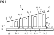
- a turbine 1 is shown, which is designed as an axial turbine 1 in the present exemplary embodiment.
- the turbine 1 is designed in four stages in the present exemplary embodiment, i.e. the turbine 1 has blading with four rotor blade rings 3a, 3b, 3c, 3d and three guide blade rings 4a, 4b, 4c, 4d.
- the rotor blade rings 3a, 3b, 3c, 3d each have a plurality of rotor blades 5, while the guide vane rings 4a, 4b, 4c, 4d each have a plurality of guide blades 6.
- the rotor blade rings 3a, 3b, 3c, 3d and the guide vane rings 4a, 4b, 4c, 4d are arranged alternately one behind the other in a housing 2 in the direction of flow of a working medium that flows through the turbine 1, starting with the guide vane ring 4a, followed by the rotor blade ring 3a etc.
- the housing 2 is conical and widens in the direction of flow S of the working medium.
- the blades 5 each have a blade 7, a platform 8 attached to the blade, a foot 9 attached to the platform 8 with a blade fastening section 10.
- the rotor blades 5 are fastened to a rotor shaft 11 of the turbine 1, in that they are inserted into respective groove-shaped receptacles 12 of the rotor shaft 11.
- the guide vanes 6 each have a guide vane leaf 3a, 3b, 3c, 3d and, at their radially outward ends, a guide vane fastening section 14, with which the guide vanes 6 are fastened to an annular guide vane carrier 15. At their radially inward ends, the guide vanes 6 each have a sealing element 16 which is arranged between rotor blade fastening sections 10 of two adjacent rotor blades 5. In order to improve a seal between the rotor blades 5 and guide blades 6, the rotor blade fastening sections 10 each have balconies 17, which are designed as extensions to the respective platform 8, which extend in or against the direction of flow.
- an original rotor blade ring 3a, 3b, 3c, 3d is removed at a first rotor blade position I.
- it is the last blade ring 3d in the flow direction S at the first blade position I.
- a replacement blade ring 3 ′ is then mounted at a second blade position II.
- the replacement blade ring 3 'at the second blade position II replaces the original blade ring 3d at the first blade position I.
- the replacement blade ring 3' consists of a plurality of replacement blades 5 '.
- the second rotor blade position II is arranged along a direction of extent of the rotor shaft 11 of the thermal turbomachine 1 in the flow direction of the working medium at a distance from the first rotor blade position I, the distance A being dimensioned such that the replacement rotor blade ring 3 'is still located within the housing 2 .
- the distance A is between 3 mm and 15 mm, e.g. 10 mm.
- the third rotor blade ring 3c, the fourth rotor blade ring 3d and the third guide vane ring 4c arranged between the third rotor blade ring 3c and fourth rotor blade ring 3d are displaced by the distance A in the direction of flow S.
- the replacement blade ring 3 ′ has a larger outer diameter than the original blade ring 3d, which is adapted to an inner diameter of the housing 2 at the second blade position II.
- a positioning element 18a is provided in order to fix the replacement rotor blade ring 3 ′ at the second rotor blade position II.
- the positioning element 18a is designed as a spacer disk or ring and has been pushed onto the rotor shaft 11 before the replacement blade ring 3 'is mounted.
- the positioning element 18b is integrally formed on the replacement blade ring 3 ', for example in the form of an extension 19 of the balcony 17.
- the positioning element 18b is formed by a rear contact surface 20, which is shortened 21 of the foot 9 is displaced forward counter to the direction of flow S. In other words, material is removed from the rear of the foot 8, so that the replacement blade ring 3 ′ can be displaced in the flow direction S due to the shortened foot 8.
- a turbine 1 can thus be modified with little effort.
Landscapes
- Engineering & Computer Science (AREA)
- Mechanical Engineering (AREA)
- General Engineering & Computer Science (AREA)
- Physics & Mathematics (AREA)
- Fluid Mechanics (AREA)
- Turbine Rotor Nozzle Sealing (AREA)
- Structures Of Non-Positive Displacement Pumps (AREA)
Claims (6)
- Procédé de modification d'une turbine (1) ayant des couronnes (3a, 3b, 3c, 3d) d'aubes mobiles et des couronnes (4a, 4b, 4c, 4d) d'aubes directrices disposées dans une enveloppe (2) de constitution conique, dans lequel on remplace une couronne (3a, 3b, 3c, 3d) d'aubes mobiles d'origine en une première position (I) d'aube mobile par une couronne (3') d'aubes mobiles de remplacement en une deuxième position (II) d'aube mobile
dans lequel, tout en conservant l'enveloppe (2), on met la deuxième position (II) d'aubes mobiles dans une direction dans laquelle s'étend un arbre de rotor de la turbine (1), dans le sens (S) d'écoulement d'un fluide de travail passant dans la turbine (1), à distance de la première position (I) d'aube mobile
dans lequel la couronne (3') d'aubes mobiles de remplacement a un diamètre extérieur plus grand que la couronne (3a, 3b, 3c, 3d) d'aubes mobiles d'origine. - Procédé suivant la revendication 1,
dans lequel on utilise un élément (18a) de mise en position pour fixer la couronne d'aubes mobiles de remplacement à la deuxième position (II) d'aube mobile et l'élément de mise en position est une pièce distincte. - Procédé suivant la revendication 1,
dans lequel on met un élément (18a, 18b) de mise en position constitué sous la forme d'un disque ou d'un anneau d'entretoisement sur l'arbre (11) du rotor pour la fixation de la couronne (3') d'aubes mobiles de remplacement en la deuxième position (II) d'aube mobile. - Procédé suivant la revendication 1,
dans lequel on forme un élément (18b) de mise en position sur la couronne (3') d'aubes mobiles de remplacement. - Procédé suivant la revendication 4,
dans lequel on forme l'élément (18b) de mise en position par un prolongement (19) sur un balcon (17) d'une emplanture (8) d'une aube (5') mobile de remplacement de la couronne (3') d'aubes mobiles de remplacement. - Procédé suivant l'une des revendications 4 ou 5,
dans lequel pour la fixation de la couronne (3') d'aubes mobiles de remplacement en la deuxième position (II) d'aube mobile, on produit un raccourcissement (21) d'une emplanture (9) d'une aube (5') mobile de remplacement de la couronne (3') d'aubes mobiles de remplacement.
Applications Claiming Priority (2)
| Application Number | Priority Date | Filing Date | Title |
|---|---|---|---|
| EP17155610.3A EP3361049A1 (fr) | 2017-02-10 | 2017-02-10 | Procédé de modification d'une turbine |
| PCT/EP2018/052803 WO2018146046A1 (fr) | 2017-02-10 | 2018-02-05 | Procédé permettant de modifier une turbine |
Publications (2)
| Publication Number | Publication Date |
|---|---|
| EP3551850A1 EP3551850A1 (fr) | 2019-10-16 |
| EP3551850B1 true EP3551850B1 (fr) | 2021-03-31 |
Family
ID=58016621
Family Applications (2)
| Application Number | Title | Priority Date | Filing Date |
|---|---|---|---|
| EP17155610.3A Withdrawn EP3361049A1 (fr) | 2017-02-10 | 2017-02-10 | Procédé de modification d'une turbine |
| EP18704502.6A Active EP3551850B1 (fr) | 2017-02-10 | 2018-02-05 | Procédé de modification d'une turbine |
Family Applications Before (1)
| Application Number | Title | Priority Date | Filing Date |
|---|---|---|---|
| EP17155610.3A Withdrawn EP3361049A1 (fr) | 2017-02-10 | 2017-02-10 | Procédé de modification d'une turbine |
Country Status (5)
| Country | Link |
|---|---|
| US (1) | US20200011182A1 (fr) |
| EP (2) | EP3361049A1 (fr) |
| KR (1) | KR20190108637A (fr) |
| CN (1) | CN110268135A (fr) |
| WO (1) | WO2018146046A1 (fr) |
Families Citing this family (1)
| Publication number | Priority date | Publication date | Assignee | Title |
|---|---|---|---|---|
| JP7261697B2 (ja) * | 2018-09-06 | 2023-04-20 | エトスエナジー・イタリア・ソシエタ・ペル・アチオニ | ガスタービンの多段式軸流圧縮機のロータを修復する方法 |
Family Cites Families (7)
| Publication number | Priority date | Publication date | Assignee | Title |
|---|---|---|---|---|
| US4900230A (en) * | 1989-04-27 | 1990-02-13 | Westinghouse Electric Corp. | Low pressure end blade for a low pressure steam turbine |
| US5110256A (en) * | 1991-02-11 | 1992-05-05 | Westinghouse Electric Corp. | Methods and apparatus for attaching a flow guide to a steam turbine for retrofit of longer rotational blades |
| US5494405A (en) * | 1995-03-20 | 1996-02-27 | Westinghouse Electric Corporation | Method of modifying a steam turbine |
| JP2003269109A (ja) * | 2002-03-18 | 2003-09-25 | Toshiba Corp | 蒸気タービン |
| US9234435B2 (en) * | 2013-03-11 | 2016-01-12 | Pratt & Whitney Canada Corp. | Tip-controlled integrally bladed rotor for gas turbine |
| US20160186593A1 (en) * | 2014-12-31 | 2016-06-30 | General Electric Company | Flowpath boundary and rotor assemblies in gas turbines |
| CN105332948B (zh) * | 2015-10-23 | 2017-08-15 | 上海交通大学 | 一种压气机仿生动叶的实现方法 |
-
2017
- 2017-02-10 EP EP17155610.3A patent/EP3361049A1/fr not_active Withdrawn
-
2018
- 2018-02-05 US US16/483,425 patent/US20200011182A1/en not_active Abandoned
- 2018-02-05 WO PCT/EP2018/052803 patent/WO2018146046A1/fr not_active Ceased
- 2018-02-05 EP EP18704502.6A patent/EP3551850B1/fr active Active
- 2018-02-05 KR KR1020197026067A patent/KR20190108637A/ko not_active Abandoned
- 2018-02-05 CN CN201880011189.0A patent/CN110268135A/zh active Pending
Non-Patent Citations (1)
| Title |
|---|
| None * |
Also Published As
| Publication number | Publication date |
|---|---|
| KR20190108637A (ko) | 2019-09-24 |
| US20200011182A1 (en) | 2020-01-09 |
| WO2018146046A1 (fr) | 2018-08-16 |
| CN110268135A (zh) | 2019-09-20 |
| EP3361049A1 (fr) | 2018-08-15 |
| EP3551850A1 (fr) | 2019-10-16 |
Similar Documents
| Publication | Publication Date | Title |
|---|---|---|
| DE69203705T2 (de) | Stator zur Einführung von Luft in das Innere einer Turbomaschine und Verfahren zum Montieren einer Schaufel dieses Stators. | |
| EP3287611B1 (fr) | Turbine à gaz | |
| DE102015201782A1 (de) | Leitschaufelring für eine Strömungsmaschine | |
| EP2918778B1 (fr) | Procédé de dimensionnement d'une turbine | |
| EP3467261B1 (fr) | Procédé de fabrication d'un élément d'aube en tandem | |
| EP2478186B1 (fr) | Rotor de turbomachine | |
| DE102015224283A1 (de) | Leitschaufelcluster für eine Strömungsmaschine | |
| EP2818724B1 (fr) | Turbomachine et procédé | |
| EP2799776A1 (fr) | Joint de brûleur pour tête de chambre de combustion de turbines à gaz et bouclier thermique | |
| WO2011124214A2 (fr) | Aube directrice d'une machine d'écoulement | |
| EP3034788A2 (fr) | Aube de compresseur d'une turbine a gaz | |
| DE102007050916A1 (de) | Verfahren und Vorrichtung zum Zusammenbau von Gasturbinen-Triebwerken | |
| EP2918776B1 (fr) | Procédé de fabrication d'une roue à aubes à deux rangées pour une turbomachine et roues à aubes à deux rangées | |
| EP2787178B1 (fr) | Ensemble d'aube directrice | |
| EP2526263B1 (fr) | Système de boîtier pour une turbomachine axiale | |
| DE102009007664A1 (de) | Abdichtvorrichtung an dem Schaufelschaft einer Rotorstufe einer axialen Strömungsmaschine | |
| EP3551850B1 (fr) | Procédé de modification d'une turbine | |
| EP3561228A1 (fr) | Aube, segment d'aube et module pour une turbomachine et turbomachine | |
| DE102019108267A1 (de) | Vorrichtung zur Befestigung von Dichtplatten zwischen Bauteilen eines Gasturbinentriebwerks | |
| EP3492701A1 (fr) | Canal d'écoulement de turbomachine | |
| EP3312388B1 (fr) | Pièce de rotor, compresseur, turbine et procédé de fabrication associés | |
| EP3056684B1 (fr) | Bague intérieure séparée axialement pour une turbomachine, un stator et groupe motopropulseur | |
| EP3428391B1 (fr) | Grille d'aube d'une turbomachine | |
| DE102019220028B4 (de) | Axialturbine | |
| EP3536913A1 (fr) | Bague intérieure pour une turbomachine et procédé de fabrication de cette bague intérieure |
Legal Events
| Date | Code | Title | Description |
|---|---|---|---|
| STAA | Information on the status of an ep patent application or granted ep patent |
Free format text: STATUS: UNKNOWN |
|
| STAA | Information on the status of an ep patent application or granted ep patent |
Free format text: STATUS: THE INTERNATIONAL PUBLICATION HAS BEEN MADE |
|
| PUAI | Public reference made under article 153(3) epc to a published international application that has entered the european phase |
Free format text: ORIGINAL CODE: 0009012 |
|
| STAA | Information on the status of an ep patent application or granted ep patent |
Free format text: STATUS: REQUEST FOR EXAMINATION WAS MADE |
|
| 17P | Request for examination filed |
Effective date: 20190710 |
|
| AK | Designated contracting states |
Kind code of ref document: A1 Designated state(s): AL AT BE BG CH CY CZ DE DK EE ES FI FR GB GR HR HU IE IS IT LI LT LU LV MC MK MT NL NO PL PT RO RS SE SI SK SM TR |
|
| AX | Request for extension of the european patent |
Extension state: BA ME |
|
| DAV | Request for validation of the european patent (deleted) | ||
| DAX | Request for extension of the european patent (deleted) | ||
| GRAP | Despatch of communication of intention to grant a patent |
Free format text: ORIGINAL CODE: EPIDOSNIGR1 |
|
| STAA | Information on the status of an ep patent application or granted ep patent |
Free format text: STATUS: GRANT OF PATENT IS INTENDED |
|
| INTG | Intention to grant announced |
Effective date: 20201117 |
|
| RAP1 | Party data changed (applicant data changed or rights of an application transferred) |
Owner name: SIEMENS ENERGY GLOBAL GMBH & CO. KG |
|
| GRAS | Grant fee paid |
Free format text: ORIGINAL CODE: EPIDOSNIGR3 |
|
| GRAA | (expected) grant |
Free format text: ORIGINAL CODE: 0009210 |
|
| STAA | Information on the status of an ep patent application or granted ep patent |
Free format text: STATUS: THE PATENT HAS BEEN GRANTED |
|
| AK | Designated contracting states |
Kind code of ref document: B1 Designated state(s): AL AT BE BG CH CY CZ DE DK EE ES FI FR GB GR HR HU IE IS IT LI LT LU LV MC MK MT NL NO PL PT RO RS SE SI SK SM TR |
|
| REG | Reference to a national code |
Ref country code: GB Ref legal event code: FG4D Free format text: NOT ENGLISH Ref country code: CH Ref legal event code: EP |
|
| REG | Reference to a national code |
Ref country code: AT Ref legal event code: REF Ref document number: 1377126 Country of ref document: AT Kind code of ref document: T Effective date: 20210415 |
|
| REG | Reference to a national code |
Ref country code: DE Ref legal event code: R096 Ref document number: 502018004527 Country of ref document: DE |
|
| REG | Reference to a national code |
Ref country code: IE Ref legal event code: FG4D Free format text: LANGUAGE OF EP DOCUMENT: GERMAN |
|
| REG | Reference to a national code |
Ref country code: LT Ref legal event code: MG9D |
|
| PG25 | Lapsed in a contracting state [announced via postgrant information from national office to epo] |
Ref country code: HR Free format text: LAPSE BECAUSE OF FAILURE TO SUBMIT A TRANSLATION OF THE DESCRIPTION OR TO PAY THE FEE WITHIN THE PRESCRIBED TIME-LIMIT Effective date: 20210331 Ref country code: FI Free format text: LAPSE BECAUSE OF FAILURE TO SUBMIT A TRANSLATION OF THE DESCRIPTION OR TO PAY THE FEE WITHIN THE PRESCRIBED TIME-LIMIT Effective date: 20210331 Ref country code: BG Free format text: LAPSE BECAUSE OF FAILURE TO SUBMIT A TRANSLATION OF THE DESCRIPTION OR TO PAY THE FEE WITHIN THE PRESCRIBED TIME-LIMIT Effective date: 20210630 Ref country code: NO Free format text: LAPSE BECAUSE OF FAILURE TO SUBMIT A TRANSLATION OF THE DESCRIPTION OR TO PAY THE FEE WITHIN THE PRESCRIBED TIME-LIMIT Effective date: 20210630 |
|
| PG25 | Lapsed in a contracting state [announced via postgrant information from national office to epo] |
Ref country code: LV Free format text: LAPSE BECAUSE OF FAILURE TO SUBMIT A TRANSLATION OF THE DESCRIPTION OR TO PAY THE FEE WITHIN THE PRESCRIBED TIME-LIMIT Effective date: 20210331 Ref country code: RS Free format text: LAPSE BECAUSE OF FAILURE TO SUBMIT A TRANSLATION OF THE DESCRIPTION OR TO PAY THE FEE WITHIN THE PRESCRIBED TIME-LIMIT Effective date: 20210331 Ref country code: SE Free format text: LAPSE BECAUSE OF FAILURE TO SUBMIT A TRANSLATION OF THE DESCRIPTION OR TO PAY THE FEE WITHIN THE PRESCRIBED TIME-LIMIT Effective date: 20210331 |
|
| REG | Reference to a national code |
Ref country code: NL Ref legal event code: MP Effective date: 20210331 |
|
| PG25 | Lapsed in a contracting state [announced via postgrant information from national office to epo] |
Ref country code: CZ Free format text: LAPSE BECAUSE OF FAILURE TO SUBMIT A TRANSLATION OF THE DESCRIPTION OR TO PAY THE FEE WITHIN THE PRESCRIBED TIME-LIMIT Effective date: 20210331 Ref country code: EE Free format text: LAPSE BECAUSE OF FAILURE TO SUBMIT A TRANSLATION OF THE DESCRIPTION OR TO PAY THE FEE WITHIN THE PRESCRIBED TIME-LIMIT Effective date: 20210331 Ref country code: LT Free format text: LAPSE BECAUSE OF FAILURE TO SUBMIT A TRANSLATION OF THE DESCRIPTION OR TO PAY THE FEE WITHIN THE PRESCRIBED TIME-LIMIT Effective date: 20210331 Ref country code: NL Free format text: LAPSE BECAUSE OF FAILURE TO SUBMIT A TRANSLATION OF THE DESCRIPTION OR TO PAY THE FEE WITHIN THE PRESCRIBED TIME-LIMIT Effective date: 20210331 Ref country code: SM Free format text: LAPSE BECAUSE OF FAILURE TO SUBMIT A TRANSLATION OF THE DESCRIPTION OR TO PAY THE FEE WITHIN THE PRESCRIBED TIME-LIMIT Effective date: 20210331 |
|
| PG25 | Lapsed in a contracting state [announced via postgrant information from national office to epo] |
Ref country code: IS Free format text: LAPSE BECAUSE OF FAILURE TO SUBMIT A TRANSLATION OF THE DESCRIPTION OR TO PAY THE FEE WITHIN THE PRESCRIBED TIME-LIMIT Effective date: 20210731 Ref country code: PT Free format text: LAPSE BECAUSE OF FAILURE TO SUBMIT A TRANSLATION OF THE DESCRIPTION OR TO PAY THE FEE WITHIN THE PRESCRIBED TIME-LIMIT Effective date: 20210802 Ref country code: PL Free format text: LAPSE BECAUSE OF FAILURE TO SUBMIT A TRANSLATION OF THE DESCRIPTION OR TO PAY THE FEE WITHIN THE PRESCRIBED TIME-LIMIT Effective date: 20210331 Ref country code: RO Free format text: LAPSE BECAUSE OF FAILURE TO SUBMIT A TRANSLATION OF THE DESCRIPTION OR TO PAY THE FEE WITHIN THE PRESCRIBED TIME-LIMIT Effective date: 20210331 Ref country code: SK Free format text: LAPSE BECAUSE OF FAILURE TO SUBMIT A TRANSLATION OF THE DESCRIPTION OR TO PAY THE FEE WITHIN THE PRESCRIBED TIME-LIMIT Effective date: 20210331 |
|
| REG | Reference to a national code |
Ref country code: DE Ref legal event code: R097 Ref document number: 502018004527 Country of ref document: DE |
|
| PG25 | Lapsed in a contracting state [announced via postgrant information from national office to epo] |
Ref country code: ES Free format text: LAPSE BECAUSE OF FAILURE TO SUBMIT A TRANSLATION OF THE DESCRIPTION OR TO PAY THE FEE WITHIN THE PRESCRIBED TIME-LIMIT Effective date: 20210331 Ref country code: DK Free format text: LAPSE BECAUSE OF FAILURE TO SUBMIT A TRANSLATION OF THE DESCRIPTION OR TO PAY THE FEE WITHIN THE PRESCRIBED TIME-LIMIT Effective date: 20210331 Ref country code: AL Free format text: LAPSE BECAUSE OF FAILURE TO SUBMIT A TRANSLATION OF THE DESCRIPTION OR TO PAY THE FEE WITHIN THE PRESCRIBED TIME-LIMIT Effective date: 20210331 |
|
| PLBE | No opposition filed within time limit |
Free format text: ORIGINAL CODE: 0009261 |
|
| STAA | Information on the status of an ep patent application or granted ep patent |
Free format text: STATUS: NO OPPOSITION FILED WITHIN TIME LIMIT |
|
| 26N | No opposition filed |
Effective date: 20220104 |
|
| PG25 | Lapsed in a contracting state [announced via postgrant information from national office to epo] |
Ref country code: IS Free format text: LAPSE BECAUSE OF FAILURE TO SUBMIT A TRANSLATION OF THE DESCRIPTION OR TO PAY THE FEE WITHIN THE PRESCRIBED TIME-LIMIT Effective date: 20210731 |
|
| REG | Reference to a national code |
Ref country code: DE Ref legal event code: R119 Ref document number: 502018004527 Country of ref document: DE |
|
| PG25 | Lapsed in a contracting state [announced via postgrant information from national office to epo] |
Ref country code: MC Free format text: LAPSE BECAUSE OF FAILURE TO SUBMIT A TRANSLATION OF THE DESCRIPTION OR TO PAY THE FEE WITHIN THE PRESCRIBED TIME-LIMIT Effective date: 20210331 |
|
| REG | Reference to a national code |
Ref country code: CH Ref legal event code: PL |
|
| REG | Reference to a national code |
Ref country code: BE Ref legal event code: MM Effective date: 20220228 |
|
| GBPC | Gb: european patent ceased through non-payment of renewal fee |
Effective date: 20220205 |
|
| PG25 | Lapsed in a contracting state [announced via postgrant information from national office to epo] |
Ref country code: LU Free format text: LAPSE BECAUSE OF NON-PAYMENT OF DUE FEES Effective date: 20220205 |
|
| PG25 | Lapsed in a contracting state [announced via postgrant information from national office to epo] |
Ref country code: FR Free format text: LAPSE BECAUSE OF NON-PAYMENT OF DUE FEES Effective date: 20220228 |
|
| PG25 | Lapsed in a contracting state [announced via postgrant information from national office to epo] |
Ref country code: LI Free format text: LAPSE BECAUSE OF NON-PAYMENT OF DUE FEES Effective date: 20220228 Ref country code: IE Free format text: LAPSE BECAUSE OF NON-PAYMENT OF DUE FEES Effective date: 20220205 Ref country code: GB Free format text: LAPSE BECAUSE OF NON-PAYMENT OF DUE FEES Effective date: 20220205 Ref country code: DE Free format text: LAPSE BECAUSE OF NON-PAYMENT OF DUE FEES Effective date: 20220901 Ref country code: CH Free format text: LAPSE BECAUSE OF NON-PAYMENT OF DUE FEES Effective date: 20220228 |
|
| PG25 | Lapsed in a contracting state [announced via postgrant information from national office to epo] |
Ref country code: BE Free format text: LAPSE BECAUSE OF NON-PAYMENT OF DUE FEES Effective date: 20220228 |
|
| REG | Reference to a national code |
Ref country code: AT Ref legal event code: MM01 Ref document number: 1377126 Country of ref document: AT Kind code of ref document: T Effective date: 20230205 |
|
| PG25 | Lapsed in a contracting state [announced via postgrant information from national office to epo] |
Ref country code: AT Free format text: LAPSE BECAUSE OF NON-PAYMENT OF DUE FEES Effective date: 20230205 |
|
| PG25 | Lapsed in a contracting state [announced via postgrant information from national office to epo] |
Ref country code: MK Free format text: LAPSE BECAUSE OF FAILURE TO SUBMIT A TRANSLATION OF THE DESCRIPTION OR TO PAY THE FEE WITHIN THE PRESCRIBED TIME-LIMIT Effective date: 20210331 Ref country code: CY Free format text: LAPSE BECAUSE OF FAILURE TO SUBMIT A TRANSLATION OF THE DESCRIPTION OR TO PAY THE FEE WITHIN THE PRESCRIBED TIME-LIMIT Effective date: 20210331 Ref country code: AT Free format text: LAPSE BECAUSE OF NON-PAYMENT OF DUE FEES Effective date: 20230205 |
|
| PG25 | Lapsed in a contracting state [announced via postgrant information from national office to epo] |
Ref country code: HU Free format text: LAPSE BECAUSE OF FAILURE TO SUBMIT A TRANSLATION OF THE DESCRIPTION OR TO PAY THE FEE WITHIN THE PRESCRIBED TIME-LIMIT; INVALID AB INITIO Effective date: 20180205 |
|
| PG25 | Lapsed in a contracting state [announced via postgrant information from national office to epo] |
Ref country code: MT Free format text: LAPSE BECAUSE OF FAILURE TO SUBMIT A TRANSLATION OF THE DESCRIPTION OR TO PAY THE FEE WITHIN THE PRESCRIBED TIME-LIMIT Effective date: 20210331 |
|
| PG25 | Lapsed in a contracting state [announced via postgrant information from national office to epo] |
Ref country code: GR Free format text: LAPSE BECAUSE OF NON-PAYMENT OF DUE FEES Effective date: 20210331 |
|
| PG25 | Lapsed in a contracting state [announced via postgrant information from national office to epo] |
Ref country code: GR Free format text: LAPSE BECAUSE OF NON-PAYMENT OF DUE FEES Effective date: 20210331 |
|
| PGFP | Annual fee paid to national office [announced via postgrant information from national office to epo] |
Ref country code: IT Payment date: 20250225 Year of fee payment: 8 |
|
| PG25 | Lapsed in a contracting state [announced via postgrant information from national office to epo] |
Ref country code: TR Free format text: LAPSE BECAUSE OF FAILURE TO SUBMIT A TRANSLATION OF THE DESCRIPTION OR TO PAY THE FEE WITHIN THE PRESCRIBED TIME-LIMIT Effective date: 20210331 |