EP3551522B1 - Assemblage d'un berceau de véhicule sur caisse comportant une pièce de fonderie - Google Patents
Assemblage d'un berceau de véhicule sur caisse comportant une pièce de fonderie Download PDFInfo
- Publication number
- EP3551522B1 EP3551522B1 EP17803972.3A EP17803972A EP3551522B1 EP 3551522 B1 EP3551522 B1 EP 3551522B1 EP 17803972 A EP17803972 A EP 17803972A EP 3551522 B1 EP3551522 B1 EP 3551522B1
- Authority
- EP
- European Patent Office
- Prior art keywords
- assembly according
- aluminum
- casting
- cradle
- side rail
- Prior art date
- Legal status (The legal status is an assumption and is not a legal conclusion. Google has not performed a legal analysis and makes no representation as to the accuracy of the status listed.)
- Active
Links
Images

Classifications
-
- B—PERFORMING OPERATIONS; TRANSPORTING
- B62—LAND VEHICLES FOR TRAVELLING OTHERWISE THAN ON RAILS
- B62D—MOTOR VEHICLES; TRAILERS
- B62D21/00—Understructures, i.e. chassis frame on which a vehicle body may be mounted
- B62D21/11—Understructures, i.e. chassis frame on which a vehicle body may be mounted with resilient means for suspension, e.g. of wheels or engine; sub-frames for mounting engine or suspensions
-
- B—PERFORMING OPERATIONS; TRANSPORTING
- B60—VEHICLES IN GENERAL
- B60G—VEHICLE SUSPENSION ARRANGEMENTS
- B60G21/00—Interconnection systems for two or more resiliently-suspended wheels, e.g. for stabilising a vehicle body with respect to acceleration, deceleration or centrifugal forces
- B60G21/005—Interconnection systems for two or more resiliently-suspended wheels, e.g. for stabilising a vehicle body with respect to acceleration, deceleration or centrifugal forces transversally
-
- B—PERFORMING OPERATIONS; TRANSPORTING
- B60—VEHICLES IN GENERAL
- B60G—VEHICLE SUSPENSION ARRANGEMENTS
- B60G7/00—Pivoted suspension arms; Accessories thereof
- B60G7/02—Attaching arms to sprung part of vehicle
-
- B—PERFORMING OPERATIONS; TRANSPORTING
- B62—LAND VEHICLES FOR TRAVELLING OTHERWISE THAN ON RAILS
- B62D—MOTOR VEHICLES; TRAILERS
- B62D25/00—Superstructure or monocoque structure sub-units; Parts or details thereof not otherwise provided for
- B62D25/08—Front or rear portions
-
- B—PERFORMING OPERATIONS; TRANSPORTING
- B62—LAND VEHICLES FOR TRAVELLING OTHERWISE THAN ON RAILS
- B62D—MOTOR VEHICLES; TRAILERS
- B62D29/00—Superstructures, understructures, or sub-units thereof, characterised by the material thereof
- B62D29/008—Superstructures, understructures, or sub-units thereof, characterised by the material thereof predominantly of light alloys, e.g. extruded
-
- C—CHEMISTRY; METALLURGY
- C22—METALLURGY; FERROUS OR NON-FERROUS ALLOYS; TREATMENT OF ALLOYS OR NON-FERROUS METALS
- C22C—ALLOYS
- C22C21/00—Alloys based on aluminium
- C22C21/02—Alloys based on aluminium with silicon as the next major constituent
Definitions
- the present invention relates to an assembly of a cradle on a vehicle body, in particular of a motor vehicle, the assembly comprising a casting part.
- the vehicle's white body is made of aluminum.
- the base of the body then mainly comprises a composition of aluminum profiles assembled by gluing, riveting and / or welding, in particular for the parts subjected to high mechanical and / or thermal stresses.
- the aim is to find a solution for assembling the cradle with the underbody and in particular the rear cradle with the rear side members for a vehicle in which the powertrain is arranged at the rear.
- the ground link functions must also be able to assemble in this area.
- vehicles are designed by assembling stamped steel parts.
- steel can be drawn easily and makes it possible to obtain resistant parts.
- the side members and the rear cradle then constitute, in a manner known per se, a structure of stamped parts.
- the parts providing the ground connection functions are assembled on folded or pressed steel parts, attached to the structure.
- the document FR2890641A1 discloses subframe side parts made by die-casting aluminum and welded to a central part of the subframe made in the form of an extruded aluminum profile. Die casting is better suited to the production of thin parts than massive parts. The small thickness has the drawback of weakening the rigidity, a drawback which the prior document proposes to remedy by providing reinforcing ribs.
- the mounting of a powertrain on the disclosed subframe poses many problems such as, for example, but not only, the support and the passage from the motor shaft to the wheels.
- the invention relates to an assembly of an aluminum cradle on a vehicle body structure comprising at least one lateral aluminum spar, characterized in that it comprises a part of aluminum foundry comprising an upper face fixed under the side spar, one or more lower parts fixed to the cradle, and an opening allowing passage of the motor shaft.
- the foundry part is obtained by gravity casting in the shell.
- the foundry part is made of an aluminum alloy comprising 6.5 to 7.5% silicon and 0.25 to 0.45% manganese offering a tensile strength of between 285 and 295 MPa.
- the opening is in the form of a semi-cylindrical concave depression made in an upper face of the casting.
- the upper face of the aluminum foundry part is fixed under the side spar by screws and / or the lower part or parts of the aluminum foundry part are fixed to the cradle by screws.
- the aluminum foundry part comprises a first pair of fins on a side wall for embedding one end of an arm or first branch of the suspension triangle.
- the aluminum foundry part comprises a second pair of fins on the same side wall to embed one end of the clamp link.
- the cast aluminum part comprises on said side wall a clevis fixing interface for embedding one end of the second branch of the suspension triangle.
- said yoke is made of steel.
- the aluminum casting part comprises a flat on which a stabilizer bar bearing is fixed.
- the bearing is made of polymer material.
- the assembly comprises a bracket secured to a transverse beam of the cradle and on which is fixed a reinforcing tie rod for a torque take-up link.
- the body structure comprises a right side spar and a left side spar welded to each end of a central cross member.
- the right side member, the left side member and the central cross member are hot extruded aluminum profiles.
- the assembly according to the invention makes it possible to obtain strong, light and compact parts on which the ground connection elements can be easily mounted.
- the design of the invention is based on the choice of making a part in cast aluminum which allows the link between the side members of the body structure of the vehicle and the cradle while providing the necessary fixings for the ground connection elements.
- the anti-roll bar, the lower suspension triangle and the gripper link can be secured securely and with the appropriate interfaces on the casting.
- the foundry process associated with a machining operation offers considerable latitude in the permitted shapes and their precision.
- the use of the foundry part makes it possible to integrate all the functions in a minimum of space, thus respecting the architectural constraints of the vehicle.
- the cast part also provides rigidity to the structure of the vehicle and in particular at the level of the rear side members largely cut to allow passage of the transmission shaft.
- an aluminum cradle assembly 30 for a vehicle on a body structure comprising a right side spar 10 and a side spar 20, both made of aluminum.
- the body structure part 40 particularly described here for a rear-wheel drive vehicle constitutes a rear body structure part.
- each of the rear side members 10, 20 comprises a respective front face 11, 21 to be fixed to a central part of the body constituting the passenger compartment of the vehicle, itself preferably in aluminum, extruded, stamped, or folded and assembled by gluing and riveting.
- the side members 10, 20, for their part, are preferably made of hot extruded aluminum.
- each side member 10 20 in other words each side member face oriented towards an outer side of the vehicle, has a concave depression 12, 22, conical with a downward point, open depression on both sides. the deepest (base of the cone) on the upper face, and the axis side of the cone on the outer lateral face of the spar, to allow passage of the damper (not shown).
- the side members 10, 20, sized to support a powertrain, are connected at the top by a central cross member 42 and at the rear end by a rear end cross member 41, both made of extruded aluminum, welded and / or screwed.
- the right side spar 10, the left side spar 20 and the central cross member 42 are for example rectilinear hot-extruded aluminum sections.
- the rear end cross member 41 is for example an extruded aluminum profile then hot bent.
- the right side member 10 and the left side member 20 are welded to each end of the central cross member 42 and the rear end cross member 41 is fixed by screws at the rear ends of the side members 10, 20.
- a piece 50 of an aluminum foundry comprises an upper face 51 which is fixed under the spar 10.
- the upper face 51 comprises a rear part 51a which is fixed at a rear position relative to the tip of the half-cone of the concave depression 12, and a front part 51b coming to be fixed at a front position relative to the point of the half-cone of the concave depression 12.
- the part 50 of the aluminum foundry makes it possible to reinforce the spar 10 under the 'location of the tip of the half-cone formed by the concave depression 12.
- an aluminum casting part 60 comprises an upper face 61 which is fixed under the spar 20 in a symmetrical manner comparable to the casting part 50 of' aluminum to reinforce the spar 20 under the location of the tip of the half-cone formed by the concave depression 22.
- the cradle 30 is more particularly here a rear cradle which comprises a right side beam 31 and a left side beam 32, connected by a rear transverse beam 34 and by a beam front transverse 33.
- the beams 31 to 34 can be made of pressed and bent aluminum. An embodiment of the beams 31 to 34 in the form of aluminum profiles, for example obtained by hot extrusion, provides better mechanical and thermal resistance.
- the front transverse beam 33 protrudes on each side of the cradle to better attach to the central unit of the vehicle.
- the rear transverse beam 34 supports a caliper 37 to which it is secured, for example by screw connection, and to which is fixed a reinforcing tie rod 38 for an engine torque take-up link (not shown).
- the aluminum casting part 50 comprises in the lower part a protuberance 52 located at the rear of an inner side face and a protuberance 53 located at the front of the inner side face.
- inner side face is understood to mean any face of the cast part oriented, in other words looking towards the interior of the engine compartment.
- the protuberances 52, 53 can be on lower parts of different levels.
- Each protuberance 52, 53 comprises a surface which is substantially but not necessarily strictly parallel to the upper face 51 of the aluminum casting part 50 and which is drilled substantially in its center to allow the passage of a fixing screw on the upper face of the lateral beam 31.
- the aluminum casting part 60 comprises in lower part a protuberance 62 located at the rear of an inner side face and a protuberance 63 located at the front of the inner side face as can also be seen on the figure 1 .
- the foundry part 50 comprises an opening 54 passing through the inner side face to the outer side face to allow passage of the motor shaft of the powertrain towards the right wheel (not shown). In this way, the foundry part 50 prevents weakening of the spar 10 by a passage of the motor shaft passing through it.
- the opening 54 can be made in tubular form, but this embodiment requires a casting piece high enough to contain the diameter of the tubular form necessary for the passage of the motor shaft.
- the opening 54 is in the form of a semi-cylindrical concave depression formed in the upper face 51 of the foundry part 50.
- the lower face of the spar 10 then comprises a semi-cylindrical concave depression 13 arranged to form a hollow cylinder of sufficient diameter to pass the drive shaft when the semi-cylindrical concave depression 13 is disposed above and facing the opening 54 in the form of a semi-cylindrical concave depression.
- the rear part 51a of the upper face 51 is then fixed in the rear position with respect to the semi-cylindrical concave depression constituting the opening 54, and the front part 51b then comes to be fixed in the front position with respect to the semi-concave depression.
- the part 50 of foundry reinforces with minimal bulk, the location of the spar 10 in which a sufficient opening can be made by concave depression, in combination with that of the foundry part for the passage of the motor shaft, as well as in its close vicinity it is possible make the opening 12, also by concave depression, sufficient for the passage of the shock absorber (not shown) as close as possible to the spar 10.
- the foundry part 60 comprises an opening 64 passing through the inner side face to the outer side face to allow passage of the motor shaft of the powertrain towards the left wheel (not shown).
- each piece of aluminum foundry by die-casting, by taking the necessary well-known measures to avoid the phenomena of shrinkage on cooling and of microbubbles, such as for example by use of a weight.
- each foundry part 50, 60 is obtained by gravity casting of aluminum.
- gravity shell casting allows the use and reuse of a permanent mold.
- the gravity shell casting process makes it possible to obtain particularly remarkable mechanical characteristics of each foundry part 50, 60 by using an appropriate aluminum alloy, in particular an aluminum alloy comprising from 6.5 to 7 , 5% silicon and 0.25 to 0.45% manganese which offers a tensile strength between 285 and 295 MPa.
- an appropriate aluminum alloy in particular an aluminum alloy comprising from 6.5 to 7 , 5% silicon and 0.25 to 0.45% manganese which offers a tensile strength between 285 and 295 MPa.
- the upper face 51, respectively 61 of the part 50, respectively 60, of aluminum foundry, is fixed under the side member 10, respectively 20 by screws 15.
- the lower part or parts 52, 53, respectively 62, 63 of the part 50, respectively 60, of aluminum foundry are fixed to the upper face of the beam 31, respectively 32 of the cradle 30 by screws.
- Steel screws are preferably used for the mechanical characteristics of this metal which are particularly suitable for fixing, previously subjected to a zinc-nickel treatment for their characteristics of making the steel in contact with aluminum compatible.
- the part 50 of aluminum casting and likewise symmetrically the part 60 of aluminum casting, comprises a first pair of fins 56 on a side wall to embed one end of the arm or first branch 91 of the suspension triangle .
- the pair of fins 56 emerges perpendicularly to the outer lateral face of the aluminum casting part 50, under the rear part 51a of the upper face 51.
- Each fin is pierced substantially at its center by an opening allowing passage.
- axis or screw 97 for maintaining the arm or first branch 91 of the suspension triangle 90.
- the part 50, and likewise symmetrically the part 60, of aluminum foundry comprises a second pair of fins 57 on said side wall to embed one end of the clamp link 92.
- the part 50, and likewise symmetrically the part 60, of foundry aluminum also comprises on the side wall an interface 58, 59 for fixing the yoke 93.
- the yoke 93 comprises two vertical walls for setting one end of the second branch 94 of the suspension triangle.
- a steel construction of the yoke 93 allows an outward facing upper portion and an inward facing lower portion to be folded. each vertical wall, without loss of mechanical quality, to come to bear respectively against two protuberances 59 and against two vertical flats 58 of the interface to be fixed there by screws.
- part 50 and likewise symmetrically the part 60, of an aluminum foundry comprises an oblique flat 55 on which is fixed a bearing 95 of stabilizer bar 96.
- An embodiment of the bearing 95 in polymer material contributes to the lightening of assembly.
- the foundry part thus makes it possible to integrate interfaces for connecting the vehicle to the ground, in addition to its function as a link between the cradle and the body structure.
Landscapes
- Engineering & Computer Science (AREA)
- Mechanical Engineering (AREA)
- Chemical & Material Sciences (AREA)
- Combustion & Propulsion (AREA)
- Transportation (AREA)
- Architecture (AREA)
- Structural Engineering (AREA)
- Body Structure For Vehicles (AREA)
- Vehicle Body Suspensions (AREA)
- Motor Or Generator Frames (AREA)
Description
- La présente invention concerne un assemblage d'un berceau sur caisse de véhicule, notamment de véhicule automobile, l'assemblage comportant une pièce de fonderie.
- Par soucis d'allégement, la caisse en blanc du véhicule est conçue en aluminium. Le soubassement de la caisse comporte alors majoritairement une composition de profilés d'aluminium assemblés par collage, rivetage et/ou soudage, notamment pour les parties soumises à des contraintes mécaniques et/ou thermiques élevées.
- Il s'agit de trouver une solution d'assemblage du berceau avec le soubassement et en particulier du berceau arrière avec les longerons arrière pour un véhicule dans lequel le groupe motopropulseur est disposé à l'arrière. Les fonctions de liaison au sol doivent également pouvoir s'assembler dans cette zone.
- Généralement, les véhicules sont conçus par assemblage de pièces d'acier embouties. En effet, l'acier est facilement emboutissable et permet d'obtenir des pièces résistantes. Les longerons et le berceau arrière constituent alors de manière connue en soi une structure de pièces embouties. De même, les pièces assurant les fonctions de liaison au sol sont assemblées sur des pièces en acier plié ou embouti, rapportées sur la structure.
- Dans le cadre d'un allégement de structure, l'utilisation de profilés extrudés limite les possibilités d'interfaçage des éléments de liaison au sol. La fonderie d'aluminium devient alors un procédé intéressant Le document
DE 10 2004 062932 A1 divulgue un berceau en aluminium et une structure de caisse de véhicule comprenant au moins un longeron latéral en aluminium. - Le document
FR2890641A1 - Pour remédier aux problèmes de l'état antérieur de la technique, l'invention a pour objet un assemblage de berceau en aluminium sur structure de caisse de véhicule comprenant au moins un longeron latéral en aluminium, caractérisé en ce qu'il comporte une pièce de fonderie d'aluminium comprenant une face supérieure fixée sous le longeron latéral, une ou plusieurs parties inférieures fixées sur le berceau, et une ouverture permettant un passage d'arbre moteur.
- Avantageusement, la pièce de fonderie est obtenue par coulée gravitaire en coquille.
- Particulièrement, la pièce de fonderie est constituée d'un alliage d'aluminium comprenant de 6,5 à 7,5% de silicium et de 0,25 à 0,45% de manganèse offrant une résistance à la traction comprise entre 285 et 295 MPa.
- Particulièrement aussi, l'ouverture est sous forme de dépression concave semi-cylindrique pratiquée dans une face supérieure de la pièce de fonderie.
- Particulièrement encore, la face supérieure de la pièce de fonderie d'aluminium est fixée sous le longeron latéral par des vis et/ou la ou les parties inférieures de la pièce de fonderie d'aluminium sont fixées sur le berceau par des vis.
- De préférence, la pièce de fonderie d'aluminium comprend une première paire d'ailettes sur une paroi latérale pour enchâsser une extrémité de bras ou de première branche de triangle de suspension.
- Plus particulièrement, la pièce de fonderie d'aluminium comprend une deuxième paire d'ailettes sur la même paroi latérale pour enchâsser une extrémité de biellette de pince.
- Plus particulièrement aussi la pièce de fonderie d'aluminium comprend sur ladite paroi latérale une interface de fixation de chape pour enchâsser une extrémité de deuxième branche de triangle de suspension.
- Notamment, ladite chape est en acier.
- Avantageusement aussi, la pièce de fonderie d'aluminium comprend un méplat sur lequel est fixé un palier de barre stabilisatrice.
- Particulièrement, le palier est en matériau polymère.
- Avantageusement encore, l'assemblage comprend un étrier solidaire d'une poutre transversale du berceau et sur lequel est fixé un tirant de renforcement pour une biellette de reprise de couple.
- De préférence, la structure de caisse comprend un longeron latéral droit et un longeron latéral gauche soudés à chaque extrémité d'une traverse centrale.
- Particulièrement, le longeron latéral droit, le longeron latéral gauche et la traverse centrale sont des profilés d'aluminium extrudés à chaud.
- D'autres caractéristiques et avantages de l'invention seront mieux compris à la lecture de la description d'un mode de réalisation nullement limitatif, et illustré par les dessins annexés, sur lesquels :
- la
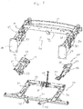
figure 1 est une vue schématique en perspective éclatée d'un assemblage de berceau sur caisse selon l'invention ; - la
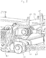
figure 2 est une vue schématique en perspective d'un détail de pièce de fonderie illustrant les principales fonctions de liaison au sol combinées à celles d'assemblage de lafigure 1 ; - la
figure 3 est une vue schématique en perspective d'une face extérieure de la pièce de fonderie prévue pour un montage d'éléments de liaison au sol ; - la
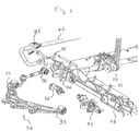
figure 4 est une vue schématique en perspective éclatée des éléments de liaison au sol associées à la pièce de fonderie fixée sur le berceau : - la
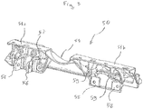
figure 5 est une vue schématique en perspective d'une face intérieure de la pièce de fonderie prévue pour sa fixation sur le berceau. - L'assemblage conforme à l'invention permet d'obtenir des pièces résistantes, légères et compactes sur lesquelles les éléments de liaison au sol peuvent venir se monter aisément.
- La conception de l'invention repose sur le choix de réaliser une pièce en fonderie d'aluminium qui permet le lien entre les longerons de la structure de caisse du véhicule et le berceau tout en offrant les fixations nécessaires aux éléments de liaison au sol. Ainsi, barre anti devers, triangle de suspension inférieur et biellette de pince peuvent venir s'arrimer solidement et avec les interfaces adéquates sur la pièce de fonderie. Le procédé de fonderie associé à une opération d'usinage offre une latitude appréciable dans les formes autorisées et leur précision. En outre, l'utilisation de la pièce de fonderie permet d'intégrer l'ensemble des fonctions dans un minimum d'espace, respectant ainsi les contraintes d'architecture du véhicule.
- Dans l'exemple de mise en œuvre présenté ci-après à titre illustratif sur un véhicule à propulsion arrière, on comprendra comment la pièce de fonderie apporte aussi de la rigidité à la structure du véhicule et en particulier au niveau des longerons arrière largement entamés pour permettre le passage de l'arbre de transmission.
- On décrit maintenant comment la pièce de fonderie assure trois fonctions essentielles qui comportent celles d'assembler le berceau arrière sur les longerons, d'offrir les interfaces des éléments de liaison au sol, et de rigidifier la structure.
- Sur la
figure 1 , on a représenté un assemblage de berceau 30 en aluminium pour véhicule sur une structure de caisse comprenant un longeron latéral droit 10 et un longeron latéral 20, l'un et l'autre en aluminium. La partie de structure de caisse 40 particulièrement décrite ici pour un véhicule à propulsion arrière, constitue une partie arrière de structure de caisse. L'homme du métier pourra aisément transposer tout au long de la lecture de la suite de la description, l'enseignement de l'invention à un véhicule à traction avant s'il en éprouve le besoin. - Dans le mode de réalisation exposé, chacun des longerons arrière 10, 20 comprend une face avant 11, 21 respective pour être fixée à une partie centrale de caisse constituant l'habitacle du véhicule, elle-même de préférence en aluminium, extrudé, embouti, ou plié et assemblé par collage-rivetage. Les longerons 10, 20, quant à eux, sont de préférence en aluminium extrudé à chaud.
- La face latérale extérieure de chaque longeron 10, 20, en d'autres termes chaque face de longeron orientée vers un côté extérieur du véhicule, comporte une dépression concave 12, 22, conique à pointe orientée vers le bas, dépression ouverte à la fois côté le plus profond (base du cône) sur la face supérieure, et côté axe du cône sur la face latérale extérieure du longeron, pour permettre un passage d'amortisseur (non représenté).
- Les longerons 10, 20, dimensionnés pour supporter un groupe motopropulseur, sont reliés en partie supérieure par une traverse centrale 42 et en extrémité arrière par une traverse extrême arrière 41, toutes deux en aluminium extrudé, soudé et/ou vissé. Le longeron latéral droit 10, le longeron latéral gauche 20 et la traverse centrale 42 sont par exemple des profilés rectilignes d'aluminium extrudés à chaud. La traverse extrême arrière 41 est par exemple un profilé d'aluminium extrudé puis cintré à chaud.
- De préférence le longeron latéral droit 10 et le longeron latéral gauche 20 sont soudés à chaque extrémité de la traverse centrale 42 et la traverse extrême arrière 41 est fixée par vis en extrémités arrières des longerons 10, 20.
- Une pièce 50 de fonderie d'aluminium comprend une face supérieure 51 qui est fixée sous le longeron 10. De préférence, la face supérieure 51 comporte une partie arrière 51a venant se fixer à une position arrière par rapport à la pointe du demi cône de la dépression concave 12, et une partie avant 51b venant se fixer à une position avant par rapport à la pointe du demi cône de la dépression concave 12. De la sorte, la pièce 50 de fonderie d'aluminium permet de renforcer le longeron 10 sous l'emplacement de la pointe de demi-cône formé par la dépression concave 12. Symétriquement, une pièce 60 de fonderie d'aluminium comprend une face supérieure 61 qui est fixée sous le longeron 20 de manière symétrique comparable à la pièce 50 de fonderie d'aluminium pour renforcer le longeron 20 sous l'emplacement de la pointe de demi-cône formé par la dépression concave 22.
- Le berceau 30 est plus particulièrement ici un berceau arrière qui comprend une poutre latérale droite 31 et une poutre latérale gauche 32, reliées par une poutre transversale arrière 34 et par une poutre transversale avant 33. Les poutres 31 à 34 peuvent être réalisées en aluminium embouti et plié. Une réalisation des poutres 31 à 34 sous forme de profilés d'aluminium, par exemple obtenus par extrusion à chaud, procure une meilleure tenue mécanique et thermique. La poutre transversale avant 33 est débordante de chaque côté du berceau pour mieux se fixer sur l'unité centrale du véhicule. La poutre transversale arrière 34 supporte un étrier 37 dont il est solidaire, par exemple par liaison vissée, et sur lequel est fixé un tirant 38 de renforcement pour une biellette de reprise de couple moteur (non représentée).
- Une poutre 35 oblique orientée à partir de la poutre 31 vers l'intérieur de l'habitacle en traversant la poutre 33 et une poutre 36 oblique orientée à partir de la poutre 32 vers l'intérieur de l'habitacle en traversant la poutre 33, permettent de diffuser les efforts par reprise sur le tunnel (non représenté) de passage de câbles et de conduites de l'avant de l'habitacle vers le compartiment moteur situé à l'arrière du véhicule.
- Au moins une partie inférieure de la pièce 50 de fonderie et de la pièce 60 de fonderie, est fixée sur le berceau 30. On entend par partie inférieure toute partie possible de la pièce de fonderie située en dessous de la face supérieure 51. Dans le mode de réalisation illustré par la
figure 5 , la pièce 50 de fonderie d'aluminium comprend en partie inférieure une excroissance 52 située à l'arrière d'une face latérale intérieure et une excroissance 53 située à l'avant de la face latérale intérieure. On entend par face latérale intérieure, toute face de la pièce de fonderie orientée, en d'autres termes regardant vers l'intérieur du compartiment moteur. Les excroissances 52, 53 peuvent être sur des parties inférieures de niveaux différents. Chaque excroissance 52, 53 comprend une surface qui est sensiblement mais non nécessairement rigoureusement parallèle à la face supérieure 51 de la pièce 50 de fonderie d'aluminium et qui est percée sensiblement en son centre pour permettre le passage d'une vis de fixation sur la face supérieure de la poutre latérale 31. De même, la pièce 60 de fonderie d'aluminium comprend en partie inférieure une excroissance 62 située à l'arrière d'une face latérale intérieure et une excroissance 63 située à l'avant de la face latérale intérieure comme on peut le voir aussi sur lafigure 1 . - La pièce 50 de fonderie comprend une ouverture 54 traversante de la face latérale intérieure à la face latérale extérieure pour permettre un passage d'arbre moteur du groupe motopropulseur vers la roue droite (non représentés). De la sorte, la pièce 50 de fonderie évite une fragilisation du longeron 10 par un passage de l'arbre moteur le traversant. On peut réaliser l'ouverture 54 sous forme tubulaire mais cette réalisation nécessite une pièce de fonderie suffisamment haute pour contenir le diamètre de la forme tubulaire nécessaire au passage de l'arbre moteur.
- Pour réduire l'encombrement de la pièce 50 de fonderie, l'ouverture 54 est sous forme de dépression concave semi-cylindrique pratiquée dans la face supérieure 51 de la pièce 50 de fonderie. La face inférieure du longeron 10 comprend alors une dépression concave semi-cylindrique 13 agencée pour former un cylindre creux de diamètre suffisant au passage de l'arbre moteur lorsque la dépression concave semi-cylindrique 13 est disposée au-dessus et en regard de l'ouverture 54 sous forme de dépression concave semi-cylindrique. La partie arrière 51a de la face supérieure 51 vient alors se fixer en position arrière par rapport à la dépression concave semi-cylindrique constituant l'ouverture 54, et la partie avant 51b vient alors se fixer en position avant par rapport à la dépression concave semi-cylindrique constituant l'ouverture 54. De la sorte, la pièce 50 de fonderie renforce à encombrement minimal, l'endroit du longeron 10 dans lequel on peut pratiquer une ouverture suffisante par dépression concave, en combinaison avec celle de la pièce de fonderie pour le passage de l'arbre moteur, ainsi que dans son voisinage proche on peut pratiquer l'ouverture 12, elle aussi par dépression concave, suffisante pour le passage de l'amortisseur (non représenté) au plus près du longeron 10.
- De même, la pièce 60 de fonderie comprend une ouverture 64 traversante de la face latérale intérieure à la face latérale extérieure pour permettre un passage d'arbre moteur du groupe motopropulseur vers la roue gauche (non représentés).
- Il est possible d'obtenir chaque pièce de fonderie d'aluminium par moulage sous pression, en prenant les mesures nécessaires bien connues pour éviter les phénomènes de retrait au refroidissement et de microbulles, comme par exemple par utilisation de masselotte. Pour atteindre plus facilement les caractéristiques mécaniques requises, chaque pièce 50, 60 de fonderie est obtenue par coulée gravitaire d'aluminium. Avantageusement par rapport au moule à sable, la coulée gravitaire en coquille permet l'utilisation et la réutilisation d'un moule permanent.
- Le procédé de coulée gravitaire en coquille permet d'obtenir des caractéristiques mécaniques particulièrement remarquables de chaque pièce 50, 60 de fonderie par utilisation d'un alliage d'aluminium approprié, notamment d'un alliage d'aluminium comprenant de 6,5 à 7,5% de silicium et de 0,25 à 0,45% de manganèse qui offre une résistance à la traction comprise entre 285 et 295 MPa.
- La face supérieure 51, respectivement 61 de la pièce 50, respectivement 60, de fonderie d'aluminium, est fixée sous le longeron 10, respectivement 20 par des vis 15. De manière comparable, la ou les parties inférieures 52, 53, respectivement 62, 63 de la pièce 50, respectivement 60, de fonderie d'aluminium, sont fixées sur la face supérieure de la poutre 31, respectivement 32 du berceau 30 par des vis. On utilise de préférence des vis en acier pour les caractéristiques mécaniques de ce métal particulièrement appropriées à la fixation, préalablement soumises à un traitement zinc-nickel pour ses caractéristiques de mise en compatibilité de l'acier en contact avec l'aluminium.
- Comme illustré par la
figure 3 , la pièce 50 de fonderie d'aluminium, et de même symétriquement la pièce 60 de fonderie d'aluminium, comprend une première paire d'ailettes 56 sur une paroi latérale pour enchâsser une extrémité de bras ou de première branche 91 de triangle de suspension. Notamment, la paire d'ailettes 56 émerge perpendiculairement à la face latérale externe de la pièce 50 de fonderie d'aluminium, sous la partie arrière 51a de la face supérieure 51. Chaque ailette est transpercée sensiblement en son centre par une ouverture permettant un passage d'axe ou de vis 97 de maintien de bras ou de première branche 91 de triangle de suspension 90. - La pièce 50, et de même symétriquement la pièce 60, de fonderie d'aluminium comprend une deuxième paire d'ailettes 57 sur ladite paroi latérale pour enchâsser une extrémité de biellette de pince 92.
- La pièce 50, et de même symétriquement la pièce 60, de fonderie d'aluminium comprend aussi sur la paroi latérale une interface 58, 59 de fixation de chape 93. Comme illustré par la
figure 4 , la chape 93 comprend deux parois verticales pour enchâsser une extrémité de deuxième branche 94 de triangle de suspension. Une fabrication en acier de la chape 93 permet de plier une partie supérieure orientée vers l'extérieur et une partie inférieure orientée vers l'intérieure de chaque paroi verticale, sans perte de qualité mécanique, pour venir s'appliquer respectivement contre deux excroissances 59 et contre deux méplats verticaux 58 de l'interface pour y être fixées par des vis. - De plus, pièce 50, et de même symétriquement la pièce 60, de fonderie d'aluminium comprend un méplat 55 oblique sur lequel est fixé un palier 95 de barre stabilisatrice 96. Une réalisation du palier 95 en matériau polymère contribue à l'allégement de l'assemblage.
- La pièce de fonderie permet ainsi d'intégrer des interfaces de liaison du véhicule au sol, en plus de sa fonction de lien entre le berceau et la structure de caisse.
Claims (15)
- Assemblage d'un berceau (30) en aluminium de véhicule sur structure de caisse comprenant au moins un longeron latéral (10, 20) en aluminium, caractérisé en ce qu'il comporte une pièce (50, 60) de fonderie d'aluminium comprenant une face supérieure (51, 61) fixée sous ledit longeron (10, 20), une ou plusieurs parties inférieures (52, 53, 62, 63) fixées sur ledit berceau (30), et une ouverture (54, 64) permettant un passage d'arbre moteur.
- Assemblage selon la revendication 1, caractérisé en ce que ladite pièce (50, 60) de fonderie est obtenue par coulée gravitaire en coquille.
- Assemblage selon la revendication 1 ou 2, caractérisé en ce que ladite pièce (50, 60) de fonderie est constituée d'un alliage d'aluminium comprenant de 6,5 à 7,5% de silicium et de 0,25 à 0,45% de manganèse offrant une résistance à la traction comprise entre 285 et 295 MPa.
- Assemblage selon l'une quelconque des revendications précédentes, caractérisé en ce que ladite ouverture (54, 64) est sous forme de dépression concave semi-cylindrique pratiquée dans ladite face supérieure (51, 61).
- Assemblage selon l'une quelconque des revendications précédentes, caractérisé en ce que ladite face supérieure (51, 61) de la pièce (50, 60) de fonderie d'aluminium est fixée sous ledit longeron (10, 20) par des vis (15).
- Assemblage selon l'une quelconque des revendications précédentes, caractérisé en ce que la ou les parties inférieures ladite pièce (50, 60) de fonderie d'aluminium (52, 53, 62, 63) sont fixées sur ledit berceau (30) par des vis.
- Assemblage selon l'une quelconque des revendications précédentes, caractérisé en ce que la pièce (50, 60) de fonderie d'aluminium comprend une première paire d'ailettes (56) sur une paroi latérale pour enchâsser une extrémité de bras ou de première branche (91) de triangle de suspension.
- Assemblage selon la revendication précédente, caractérisé en ce que la pièce (50, 60) de fonderie d'aluminium comprend une deuxième paire d'ailettes (57) sur ladite paroi latérale pour enchâsser une extrémité de biellette de pince (92).
- Assemblage selon l'une quelconque des revendications 7 ou 8, caractérisé en ce que la pièce (50, 60) de fonderie d'aluminium comprend sur ladite paroi latérale une interface (58, 59) de fixation de chape (93) pour enchâsser une extrémité de deuxième branche (94) de triangle de suspension.
- Assemblage selon la revendication précédente, caractérisé en ce que ladite chape (93) est en acier.
- Assemblage selon l'une quelconque des revendications précédentes, caractérisé en ce que ladite pièce (50, 60) de fonderie d'aluminium comprend un méplat (59) sur lequel est fixé un palier (95) de barre stabilisatrice (96).
- Assemblage selon la revendication précédente, caractérisé en ce que ledit palier (95) est en matériau polymère.
- Assemblage selon l'une quelconque des revendications précédentes, caractérisé en ce qu'il comprend un étrier (37) solidaire d'une poutre transversale du berceau (30) et sur lequel est fixé un tirant de renforcement pour une biellette de reprise de couple.
- Assemblage selon l'une quelconque des revendications précédentes, caractérisé en ce que la structure de caisse comprend un longeron latéral droit (10) et un longeron latéral gauche (20) soudés à chaque extrémité d'une traverse centrale (42).
- Assemblage selon la revendication 14, caractérisé en ce que le longeron latéral droit (10), le longeron latéral gauche (20) et la traverse centrale (42) sont des profilés d'aluminium extrudés à chaud.
Applications Claiming Priority (2)
| Application Number | Priority Date | Filing Date | Title |
|---|---|---|---|
| FR1661986A FR3059630B1 (fr) | 2016-12-06 | 2016-12-06 | Assemblage d'un berceau de vehicule sur caisse comportant une piece de fonderie |
| PCT/EP2017/080754 WO2018104119A1 (fr) | 2016-12-06 | 2017-11-29 | Assemblage d'un berceau de véhicule sur caisse comportant une pièce de fonderie |
Publications (2)
| Publication Number | Publication Date |
|---|---|
| EP3551522A1 EP3551522A1 (fr) | 2019-10-16 |
| EP3551522B1 true EP3551522B1 (fr) | 2020-12-30 |
Family
ID=58228201
Family Applications (1)
| Application Number | Title | Priority Date | Filing Date |
|---|---|---|---|
| EP17803972.3A Active EP3551522B1 (fr) | 2016-12-06 | 2017-11-29 | Assemblage d'un berceau de véhicule sur caisse comportant une pièce de fonderie |
Country Status (7)
| Country | Link |
|---|---|
| US (1) | US20190337567A1 (fr) |
| EP (1) | EP3551522B1 (fr) |
| JP (1) | JP7041153B2 (fr) |
| KR (1) | KR102277049B1 (fr) |
| CN (1) | CN109982916B (fr) |
| FR (1) | FR3059630B1 (fr) |
| WO (1) | WO2018104119A1 (fr) |
Families Citing this family (2)
| Publication number | Priority date | Publication date | Assignee | Title |
|---|---|---|---|---|
| US10300950B2 (en) * | 2014-03-31 | 2019-05-28 | Yorozu Corp. | Suspension member and method for manufacturing same |
| US10960518B1 (en) * | 2019-09-20 | 2021-03-30 | Anthony M. Barraco | Inserts for shielding aluminum vehicles from clamps |
Family Cites Families (15)
| Publication number | Priority date | Publication date | Assignee | Title |
|---|---|---|---|---|
| US5879026A (en) * | 1995-12-19 | 1999-03-09 | Chrysler Corporation | Vehicle suspension and steering cradle |
| US5947519A (en) | 1998-03-06 | 1999-09-07 | Chrysler Corporation | Extruded node for vehicle frame |
| JP3921314B2 (ja) * | 1999-09-03 | 2007-05-30 | 株式会社神戸製鋼所 | 衝撃破壊強度に優れたアルミニウム合金鋳造材およびその製造方法 |
| US6866295B2 (en) | 2000-12-28 | 2005-03-15 | Dana Corporation | Modular cast independent front suspension subframe |
| GB0319491D0 (en) * | 2003-08-20 | 2003-09-17 | Ford Global Tech Llc | Bonded structural joints |
| DE102004062932B4 (de) * | 2004-12-28 | 2018-09-06 | Volkswagen Ag | Hintere Bodenstruktur eines Kraftfahrzeugs |
| DE102006062813B4 (de) * | 2005-09-09 | 2014-05-28 | Ksm Castings Group Gmbh | Achsträger |
| ATE489277T1 (de) | 2005-09-13 | 2010-12-15 | Ksm Castings Gmbh | Hilfsrahmen, insbesondere für kraftfahrzeuge |
| DE102006013548C5 (de) * | 2006-03-24 | 2018-01-18 | Audi Ag | Als Fahrschemel ausgebildeter Hilfsrahmen für Kraftfahrzeuge sowie Fahrzeugkarosserie |
| JP4994734B2 (ja) * | 2006-07-24 | 2012-08-08 | 株式会社大紀アルミニウム工業所 | 鋳造用アルミニウム合金および同アルミニウム合金鋳物 |
| EP2098604A4 (fr) | 2006-12-13 | 2014-07-23 | Sumitomo Light Metal Ind | Produits en alliage à base d'aluminium à forte résistance et leur procédé de production |
| DE102011106619A1 (de) * | 2011-06-16 | 2012-12-20 | GM Global Technology Operations LLC (n. d. Gesetzen des Staates Delaware) | Vorderachssystem für ein Fahrzeug und Kraftfahrzeug |
| FR3000009B1 (fr) * | 2012-12-20 | 2018-08-03 | Renault S.A.S. | Dispositif de liaison d'un berceau automobile |
| WO2014097513A1 (fr) * | 2012-12-21 | 2014-06-26 | 本田技研工業株式会社 | Structure de carrosserie de véhicule |
| JP5983400B2 (ja) * | 2012-12-28 | 2016-08-31 | マツダ株式会社 | 前部車体構造 |
-
2016
- 2016-12-06 FR FR1661986A patent/FR3059630B1/fr not_active Expired - Fee Related
-
2017
- 2017-11-29 US US16/462,096 patent/US20190337567A1/en not_active Abandoned
- 2017-11-29 JP JP2019530077A patent/JP7041153B2/ja active Active
- 2017-11-29 CN CN201780072021.6A patent/CN109982916B/zh active Active
- 2017-11-29 WO PCT/EP2017/080754 patent/WO2018104119A1/fr not_active Ceased
- 2017-11-29 EP EP17803972.3A patent/EP3551522B1/fr active Active
- 2017-11-29 KR KR1020197016338A patent/KR102277049B1/ko active Active
Non-Patent Citations (1)
| Title |
|---|
| None * |
Also Published As
| Publication number | Publication date |
|---|---|
| CN109982916A (zh) | 2019-07-05 |
| JP7041153B2 (ja) | 2022-03-23 |
| EP3551522A1 (fr) | 2019-10-16 |
| FR3059630B1 (fr) | 2020-02-14 |
| WO2018104119A1 (fr) | 2018-06-14 |
| US20190337567A1 (en) | 2019-11-07 |
| CN109982916B (zh) | 2022-07-22 |
| JP2019535589A (ja) | 2019-12-12 |
| KR20190092424A (ko) | 2019-08-07 |
| KR102277049B1 (ko) | 2021-07-13 |
| FR3059630A1 (fr) | 2018-06-08 |
Similar Documents
| Publication | Publication Date | Title |
|---|---|---|
| EP3551484B1 (fr) | Dispositif de liaison entre un longeron en aluminium de véhicule et un bras de suspension | |
| EP3003826B1 (fr) | Berceau pour train roulant de véhicule automobile | |
| FR2550155A1 (fr) | ||
| FR2986489A1 (fr) | Berceau moteur monobloc extrude | |
| WO2018104119A1 (fr) | Assemblage d'un berceau de véhicule sur caisse comportant une pièce de fonderie | |
| EP2436579A2 (fr) | Ensemble de traverse de planche de bord pour véhicule automobile. | |
| EP3119665B1 (fr) | Structure arrière de véhicule automobile | |
| EP4124478A1 (fr) | Bras ou triangle de suspension et procédé de fabrication d'un tel bras ou triangle de suspension | |
| EP3204247B1 (fr) | Bras de suspension de véhicule automobile | |
| EP3386845B1 (fr) | Elément de carrosserie pour véhicule automobile et procédé de fabrication correspondant | |
| WO2010076441A1 (fr) | Ensemble comprenant un cadre avant et un berceau de vehicule automobile et vehicule comportant un tel ensemble | |
| FR3139783A1 (fr) | extension de longeronnet arrière pour véhicule automobile | |
| FR3044601A1 (fr) | "essieu arriere de vehicule automobile comportant des moyens de retenue pour ameliorer la liaison par collage d'une traverse en materiau composite avec les bras" | |
| EP3333050B1 (fr) | Fixation par demi-coques d'un jambage de traverse de poste de conduite de véhicule | |
| FR3080348A1 (fr) | Structure de caisse d'un vehicule automobile comprenant un agencement de renfort en extremite de longeron. | |
| FR3167074A1 (fr) | Fixation de rotule sur un bras de suspension de véhicule automobile | |
| FR2874574A1 (fr) | Chassis pour motoquad et motoquad correspondant | |
| WO2022258899A1 (fr) | Structure de caisse de véhicule automobile | |
| FR3030431A1 (fr) | Nœud de structure avant d'un vehicule automobile. | |
| FR3027865A1 (fr) | Custode pour vehicule automobile et procede de formage par fonderie d'une telle piece | |
| FR3141431A1 (fr) | Pièce de renfort à encaissement d’efforts transversaux, pour une prolonge de berceau d’une structure de véhicule automobile | |
| EP2170637A1 (fr) | Essieu-arriere de vehicule automobile de structure en h ayant une traverse a profil ferme | |
| FR2836885A1 (fr) | Element de structure et structure arriere d'un vehicule automobile, procede de fabrication d'une telle structure |
Legal Events
| Date | Code | Title | Description |
|---|---|---|---|
| STAA | Information on the status of an ep patent application or granted ep patent |
Free format text: STATUS: UNKNOWN |
|
| STAA | Information on the status of an ep patent application or granted ep patent |
Free format text: STATUS: THE INTERNATIONAL PUBLICATION HAS BEEN MADE |
|
| PUAI | Public reference made under article 153(3) epc to a published international application that has entered the european phase |
Free format text: ORIGINAL CODE: 0009012 |
|
| STAA | Information on the status of an ep patent application or granted ep patent |
Free format text: STATUS: REQUEST FOR EXAMINATION WAS MADE |
|
| 17P | Request for examination filed |
Effective date: 20190520 |
|
| AK | Designated contracting states |
Kind code of ref document: A1 Designated state(s): AL AT BE BG CH CY CZ DE DK EE ES FI FR GB GR HR HU IE IS IT LI LT LU LV MC MK MT NL NO PL PT RO RS SE SI SK SM TR |
|
| AX | Request for extension of the european patent |
Extension state: BA ME |
|
| DAV | Request for validation of the european patent (deleted) | ||
| DAX | Request for extension of the european patent (deleted) | ||
| GRAP | Despatch of communication of intention to grant a patent |
Free format text: ORIGINAL CODE: EPIDOSNIGR1 |
|
| STAA | Information on the status of an ep patent application or granted ep patent |
Free format text: STATUS: GRANT OF PATENT IS INTENDED |
|
| INTG | Intention to grant announced |
Effective date: 20200707 |
|
| GRAS | Grant fee paid |
Free format text: ORIGINAL CODE: EPIDOSNIGR3 |
|
| GRAA | (expected) grant |
Free format text: ORIGINAL CODE: 0009210 |
|
| STAA | Information on the status of an ep patent application or granted ep patent |
Free format text: STATUS: THE PATENT HAS BEEN GRANTED |
|
| AK | Designated contracting states |
Kind code of ref document: B1 Designated state(s): AL AT BE BG CH CY CZ DE DK EE ES FI FR GB GR HR HU IE IS IT LI LT LU LV MC MK MT NL NO PL PT RO RS SE SI SK SM TR |
|
| REG | Reference to a national code |
Ref country code: GB Ref legal event code: FG4D Free format text: NOT ENGLISH |
|
| REG | Reference to a national code |
Ref country code: AT Ref legal event code: REF Ref document number: 1349672 Country of ref document: AT Kind code of ref document: T Effective date: 20210115 |
|
| REG | Reference to a national code |
Ref country code: DE Ref legal event code: R096 Ref document number: 602017030620 Country of ref document: DE |
|
| REG | Reference to a national code |
Ref country code: IE Ref legal event code: FG4D Free format text: LANGUAGE OF EP DOCUMENT: FRENCH |
|
| PG25 | Lapsed in a contracting state [announced via postgrant information from national office to epo] |
Ref country code: NO Free format text: LAPSE BECAUSE OF FAILURE TO SUBMIT A TRANSLATION OF THE DESCRIPTION OR TO PAY THE FEE WITHIN THE PRESCRIBED TIME-LIMIT Effective date: 20210330 Ref country code: GR Free format text: LAPSE BECAUSE OF FAILURE TO SUBMIT A TRANSLATION OF THE DESCRIPTION OR TO PAY THE FEE WITHIN THE PRESCRIBED TIME-LIMIT Effective date: 20210331 Ref country code: RS Free format text: LAPSE BECAUSE OF FAILURE TO SUBMIT A TRANSLATION OF THE DESCRIPTION OR TO PAY THE FEE WITHIN THE PRESCRIBED TIME-LIMIT Effective date: 20201230 Ref country code: FI Free format text: LAPSE BECAUSE OF FAILURE TO SUBMIT A TRANSLATION OF THE DESCRIPTION OR TO PAY THE FEE WITHIN THE PRESCRIBED TIME-LIMIT Effective date: 20201230 |
|
| REG | Reference to a national code |
Ref country code: AT Ref legal event code: MK05 Ref document number: 1349672 Country of ref document: AT Kind code of ref document: T Effective date: 20201230 |
|
| PG25 | Lapsed in a contracting state [announced via postgrant information from national office to epo] |
Ref country code: SE Free format text: LAPSE BECAUSE OF FAILURE TO SUBMIT A TRANSLATION OF THE DESCRIPTION OR TO PAY THE FEE WITHIN THE PRESCRIBED TIME-LIMIT Effective date: 20201230 Ref country code: LV Free format text: LAPSE BECAUSE OF FAILURE TO SUBMIT A TRANSLATION OF THE DESCRIPTION OR TO PAY THE FEE WITHIN THE PRESCRIBED TIME-LIMIT Effective date: 20201230 Ref country code: BG Free format text: LAPSE BECAUSE OF FAILURE TO SUBMIT A TRANSLATION OF THE DESCRIPTION OR TO PAY THE FEE WITHIN THE PRESCRIBED TIME-LIMIT Effective date: 20210330 |
|
| REG | Reference to a national code |
Ref country code: NL Ref legal event code: MP Effective date: 20201230 |
|
| PG25 | Lapsed in a contracting state [announced via postgrant information from national office to epo] |
Ref country code: HR Free format text: LAPSE BECAUSE OF FAILURE TO SUBMIT A TRANSLATION OF THE DESCRIPTION OR TO PAY THE FEE WITHIN THE PRESCRIBED TIME-LIMIT Effective date: 20201230 |
|
| REG | Reference to a national code |
Ref country code: LT Ref legal event code: MG9D |
|
| PG25 | Lapsed in a contracting state [announced via postgrant information from national office to epo] |
Ref country code: PT Free format text: LAPSE BECAUSE OF FAILURE TO SUBMIT A TRANSLATION OF THE DESCRIPTION OR TO PAY THE FEE WITHIN THE PRESCRIBED TIME-LIMIT Effective date: 20210430 Ref country code: RO Free format text: LAPSE BECAUSE OF FAILURE TO SUBMIT A TRANSLATION OF THE DESCRIPTION OR TO PAY THE FEE WITHIN THE PRESCRIBED TIME-LIMIT Effective date: 20201230 Ref country code: SK Free format text: LAPSE BECAUSE OF FAILURE TO SUBMIT A TRANSLATION OF THE DESCRIPTION OR TO PAY THE FEE WITHIN THE PRESCRIBED TIME-LIMIT Effective date: 20201230 Ref country code: EE Free format text: LAPSE BECAUSE OF FAILURE TO SUBMIT A TRANSLATION OF THE DESCRIPTION OR TO PAY THE FEE WITHIN THE PRESCRIBED TIME-LIMIT Effective date: 20201230 Ref country code: CZ Free format text: LAPSE BECAUSE OF FAILURE TO SUBMIT A TRANSLATION OF THE DESCRIPTION OR TO PAY THE FEE WITHIN THE PRESCRIBED TIME-LIMIT Effective date: 20201230 Ref country code: LT Free format text: LAPSE BECAUSE OF FAILURE TO SUBMIT A TRANSLATION OF THE DESCRIPTION OR TO PAY THE FEE WITHIN THE PRESCRIBED TIME-LIMIT Effective date: 20201230 |
|
| PG25 | Lapsed in a contracting state [announced via postgrant information from national office to epo] |
Ref country code: AT Free format text: LAPSE BECAUSE OF FAILURE TO SUBMIT A TRANSLATION OF THE DESCRIPTION OR TO PAY THE FEE WITHIN THE PRESCRIBED TIME-LIMIT Effective date: 20201230 Ref country code: PL Free format text: LAPSE BECAUSE OF FAILURE TO SUBMIT A TRANSLATION OF THE DESCRIPTION OR TO PAY THE FEE WITHIN THE PRESCRIBED TIME-LIMIT Effective date: 20201230 |
|
| PG25 | Lapsed in a contracting state [announced via postgrant information from national office to epo] |
Ref country code: IS Free format text: LAPSE BECAUSE OF FAILURE TO SUBMIT A TRANSLATION OF THE DESCRIPTION OR TO PAY THE FEE WITHIN THE PRESCRIBED TIME-LIMIT Effective date: 20210430 |
|
| REG | Reference to a national code |
Ref country code: DE Ref legal event code: R097 Ref document number: 602017030620 Country of ref document: DE |
|
| PG25 | Lapsed in a contracting state [announced via postgrant information from national office to epo] |
Ref country code: IT Free format text: LAPSE BECAUSE OF FAILURE TO SUBMIT A TRANSLATION OF THE DESCRIPTION OR TO PAY THE FEE WITHIN THE PRESCRIBED TIME-LIMIT Effective date: 20201230 Ref country code: AL Free format text: LAPSE BECAUSE OF FAILURE TO SUBMIT A TRANSLATION OF THE DESCRIPTION OR TO PAY THE FEE WITHIN THE PRESCRIBED TIME-LIMIT Effective date: 20201230 |
|
| PLBE | No opposition filed within time limit |
Free format text: ORIGINAL CODE: 0009261 |
|
| STAA | Information on the status of an ep patent application or granted ep patent |
Free format text: STATUS: NO OPPOSITION FILED WITHIN TIME LIMIT |
|
| PG25 | Lapsed in a contracting state [announced via postgrant information from national office to epo] |
Ref country code: DK Free format text: LAPSE BECAUSE OF FAILURE TO SUBMIT A TRANSLATION OF THE DESCRIPTION OR TO PAY THE FEE WITHIN THE PRESCRIBED TIME-LIMIT Effective date: 20201230 |
|
| 26N | No opposition filed |
Effective date: 20211001 |
|
| PG25 | Lapsed in a contracting state [announced via postgrant information from national office to epo] |
Ref country code: ES Free format text: LAPSE BECAUSE OF FAILURE TO SUBMIT A TRANSLATION OF THE DESCRIPTION OR TO PAY THE FEE WITHIN THE PRESCRIBED TIME-LIMIT Effective date: 20201230 |
|
| PG25 | Lapsed in a contracting state [announced via postgrant information from national office to epo] |
Ref country code: SI Free format text: LAPSE BECAUSE OF FAILURE TO SUBMIT A TRANSLATION OF THE DESCRIPTION OR TO PAY THE FEE WITHIN THE PRESCRIBED TIME-LIMIT Effective date: 20201230 |
|
| PG25 | Lapsed in a contracting state [announced via postgrant information from national office to epo] |
Ref country code: IS Free format text: LAPSE BECAUSE OF FAILURE TO SUBMIT A TRANSLATION OF THE DESCRIPTION OR TO PAY THE FEE WITHIN THE PRESCRIBED TIME-LIMIT Effective date: 20210430 |
|
| PG25 | Lapsed in a contracting state [announced via postgrant information from national office to epo] |
Ref country code: MC Free format text: LAPSE BECAUSE OF FAILURE TO SUBMIT A TRANSLATION OF THE DESCRIPTION OR TO PAY THE FEE WITHIN THE PRESCRIBED TIME-LIMIT Effective date: 20201230 |
|
| REG | Reference to a national code |
Ref country code: CH Ref legal event code: PL |
|
| PG25 | Lapsed in a contracting state [announced via postgrant information from national office to epo] |
Ref country code: LU Free format text: LAPSE BECAUSE OF NON-PAYMENT OF DUE FEES Effective date: 20211129 Ref country code: BE Free format text: LAPSE BECAUSE OF NON-PAYMENT OF DUE FEES Effective date: 20211130 |
|
| REG | Reference to a national code |
Ref country code: BE Ref legal event code: MM Effective date: 20211130 |
|
| PG25 | Lapsed in a contracting state [announced via postgrant information from national office to epo] |
Ref country code: LI Free format text: LAPSE BECAUSE OF NON-PAYMENT OF DUE FEES Effective date: 20211130 Ref country code: CH Free format text: LAPSE BECAUSE OF NON-PAYMENT OF DUE FEES Effective date: 20211130 |
|
| PG25 | Lapsed in a contracting state [announced via postgrant information from national office to epo] |
Ref country code: IE Free format text: LAPSE BECAUSE OF NON-PAYMENT OF DUE FEES Effective date: 20211129 |
|
| PG25 | Lapsed in a contracting state [announced via postgrant information from national office to epo] |
Ref country code: NL Free format text: LAPSE BECAUSE OF NON-PAYMENT OF DUE FEES Effective date: 20201230 Ref country code: CY Free format text: LAPSE BECAUSE OF FAILURE TO SUBMIT A TRANSLATION OF THE DESCRIPTION OR TO PAY THE FEE WITHIN THE PRESCRIBED TIME-LIMIT Effective date: 20201230 |
|
| P01 | Opt-out of the competence of the unified patent court (upc) registered |
Effective date: 20230608 |
|
| PG25 | Lapsed in a contracting state [announced via postgrant information from national office to epo] |
Ref country code: SM Free format text: LAPSE BECAUSE OF FAILURE TO SUBMIT A TRANSLATION OF THE DESCRIPTION OR TO PAY THE FEE WITHIN THE PRESCRIBED TIME-LIMIT Effective date: 20201230 Ref country code: HU Free format text: LAPSE BECAUSE OF FAILURE TO SUBMIT A TRANSLATION OF THE DESCRIPTION OR TO PAY THE FEE WITHIN THE PRESCRIBED TIME-LIMIT; INVALID AB INITIO Effective date: 20171129 |
|
| PG25 | Lapsed in a contracting state [announced via postgrant information from national office to epo] |
Ref country code: MK Free format text: LAPSE BECAUSE OF FAILURE TO SUBMIT A TRANSLATION OF THE DESCRIPTION OR TO PAY THE FEE WITHIN THE PRESCRIBED TIME-LIMIT Effective date: 20201230 |
|
| PG25 | Lapsed in a contracting state [announced via postgrant information from national office to epo] |
Ref country code: TR Free format text: LAPSE BECAUSE OF FAILURE TO SUBMIT A TRANSLATION OF THE DESCRIPTION OR TO PAY THE FEE WITHIN THE PRESCRIBED TIME-LIMIT Effective date: 20201230 |
|
| PG25 | Lapsed in a contracting state [announced via postgrant information from national office to epo] |
Ref country code: MT Free format text: LAPSE BECAUSE OF FAILURE TO SUBMIT A TRANSLATION OF THE DESCRIPTION OR TO PAY THE FEE WITHIN THE PRESCRIBED TIME-LIMIT Effective date: 20201230 |
|
| PGFP | Annual fee paid to national office [announced via postgrant information from national office to epo] |
Ref country code: DE Payment date: 20251119 Year of fee payment: 9 |
|
| PGFP | Annual fee paid to national office [announced via postgrant information from national office to epo] |
Ref country code: GB Payment date: 20251121 Year of fee payment: 9 |
|
| PGFP | Annual fee paid to national office [announced via postgrant information from national office to epo] |
Ref country code: FR Payment date: 20251126 Year of fee payment: 9 |