EP3551522B1 - Montage einer fahrzeughalterung an einer karosserie mit einem gussteil - Google Patents
Montage einer fahrzeughalterung an einer karosserie mit einem gussteil Download PDFInfo
- Publication number
- EP3551522B1 EP3551522B1 EP17803972.3A EP17803972A EP3551522B1 EP 3551522 B1 EP3551522 B1 EP 3551522B1 EP 17803972 A EP17803972 A EP 17803972A EP 3551522 B1 EP3551522 B1 EP 3551522B1
- Authority
- EP
- European Patent Office
- Prior art keywords
- assembly according
- aluminum
- casting
- cradle
- side rail
- Prior art date
- Legal status (The legal status is an assumption and is not a legal conclusion. Google has not performed a legal analysis and makes no representation as to the accuracy of the status listed.)
- Active
Links
Images

Classifications
-
- B—PERFORMING OPERATIONS; TRANSPORTING
- B62—LAND VEHICLES FOR TRAVELLING OTHERWISE THAN ON RAILS
- B62D—MOTOR VEHICLES; TRAILERS
- B62D21/00—Understructures, i.e. chassis frame on which a vehicle body may be mounted
- B62D21/11—Understructures, i.e. chassis frame on which a vehicle body may be mounted with resilient means for suspension, e.g. of wheels or engine; sub-frames for mounting engine or suspensions
-
- B—PERFORMING OPERATIONS; TRANSPORTING
- B60—VEHICLES IN GENERAL
- B60G—VEHICLE SUSPENSION ARRANGEMENTS
- B60G21/00—Interconnection systems for two or more resiliently-suspended wheels, e.g. for stabilising a vehicle body with respect to acceleration, deceleration or centrifugal forces
- B60G21/005—Interconnection systems for two or more resiliently-suspended wheels, e.g. for stabilising a vehicle body with respect to acceleration, deceleration or centrifugal forces transversally
-
- B—PERFORMING OPERATIONS; TRANSPORTING
- B60—VEHICLES IN GENERAL
- B60G—VEHICLE SUSPENSION ARRANGEMENTS
- B60G7/00—Pivoted suspension arms; Accessories thereof
- B60G7/02—Attaching arms to sprung part of vehicle
-
- B—PERFORMING OPERATIONS; TRANSPORTING
- B62—LAND VEHICLES FOR TRAVELLING OTHERWISE THAN ON RAILS
- B62D—MOTOR VEHICLES; TRAILERS
- B62D25/00—Superstructure or monocoque structure sub-units; Parts or details thereof not otherwise provided for
- B62D25/08—Front or rear portions
-
- B—PERFORMING OPERATIONS; TRANSPORTING
- B62—LAND VEHICLES FOR TRAVELLING OTHERWISE THAN ON RAILS
- B62D—MOTOR VEHICLES; TRAILERS
- B62D29/00—Superstructures, understructures, or sub-units thereof, characterised by the material thereof
- B62D29/008—Superstructures, understructures, or sub-units thereof, characterised by the material thereof predominantly of light alloys, e.g. extruded
-
- C—CHEMISTRY; METALLURGY
- C22—METALLURGY; FERROUS OR NON-FERROUS ALLOYS; TREATMENT OF ALLOYS OR NON-FERROUS METALS
- C22C—ALLOYS
- C22C21/00—Alloys based on aluminium
- C22C21/02—Alloys based on aluminium with silicon as the next major constituent
Definitions
- the present invention relates to an assembly of a cradle on a vehicle body, in particular of a motor vehicle, the assembly comprising a casting part.
- the vehicle's white body is made of aluminum.
- the base of the body then mainly comprises a composition of aluminum profiles assembled by gluing, riveting and / or welding, in particular for the parts subjected to high mechanical and / or thermal stresses.
- the aim is to find a solution for assembling the cradle with the underbody and in particular the rear cradle with the rear side members for a vehicle in which the powertrain is arranged at the rear.
- the ground link functions must also be able to assemble in this area.
- vehicles are designed by assembling stamped steel parts.
- steel can be drawn easily and makes it possible to obtain resistant parts.
- the side members and the rear cradle then constitute, in a manner known per se, a structure of stamped parts.
- the parts providing the ground connection functions are assembled on folded or pressed steel parts, attached to the structure.
- the document FR2890641A1 discloses subframe side parts made by die-casting aluminum and welded to a central part of the subframe made in the form of an extruded aluminum profile. Die casting is better suited to the production of thin parts than massive parts. The small thickness has the drawback of weakening the rigidity, a drawback which the prior document proposes to remedy by providing reinforcing ribs.
- the mounting of a powertrain on the disclosed subframe poses many problems such as, for example, but not only, the support and the passage from the motor shaft to the wheels.
- the invention relates to an assembly of an aluminum cradle on a vehicle body structure comprising at least one lateral aluminum spar, characterized in that it comprises a part of aluminum foundry comprising an upper face fixed under the side spar, one or more lower parts fixed to the cradle, and an opening allowing passage of the motor shaft.
- the foundry part is obtained by gravity casting in the shell.
- the foundry part is made of an aluminum alloy comprising 6.5 to 7.5% silicon and 0.25 to 0.45% manganese offering a tensile strength of between 285 and 295 MPa.
- the opening is in the form of a semi-cylindrical concave depression made in an upper face of the casting.
- the upper face of the aluminum foundry part is fixed under the side spar by screws and / or the lower part or parts of the aluminum foundry part are fixed to the cradle by screws.
- the aluminum foundry part comprises a first pair of fins on a side wall for embedding one end of an arm or first branch of the suspension triangle.
- the aluminum foundry part comprises a second pair of fins on the same side wall to embed one end of the clamp link.
- the cast aluminum part comprises on said side wall a clevis fixing interface for embedding one end of the second branch of the suspension triangle.
- said yoke is made of steel.
- the aluminum casting part comprises a flat on which a stabilizer bar bearing is fixed.
- the bearing is made of polymer material.
- the assembly comprises a bracket secured to a transverse beam of the cradle and on which is fixed a reinforcing tie rod for a torque take-up link.
- the body structure comprises a right side spar and a left side spar welded to each end of a central cross member.
- the right side member, the left side member and the central cross member are hot extruded aluminum profiles.
- the assembly according to the invention makes it possible to obtain strong, light and compact parts on which the ground connection elements can be easily mounted.
- the design of the invention is based on the choice of making a part in cast aluminum which allows the link between the side members of the body structure of the vehicle and the cradle while providing the necessary fixings for the ground connection elements.
- the anti-roll bar, the lower suspension triangle and the gripper link can be secured securely and with the appropriate interfaces on the casting.
- the foundry process associated with a machining operation offers considerable latitude in the permitted shapes and their precision.
- the use of the foundry part makes it possible to integrate all the functions in a minimum of space, thus respecting the architectural constraints of the vehicle.
- the cast part also provides rigidity to the structure of the vehicle and in particular at the level of the rear side members largely cut to allow passage of the transmission shaft.
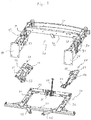
- an aluminum cradle assembly 30 for a vehicle on a body structure comprising a right side spar 10 and a side spar 20, both made of aluminum.
- the body structure part 40 particularly described here for a rear-wheel drive vehicle constitutes a rear body structure part.
- each of the rear side members 10, 20 comprises a respective front face 11, 21 to be fixed to a central part of the body constituting the passenger compartment of the vehicle, itself preferably in aluminum, extruded, stamped, or folded and assembled by gluing and riveting.
- the side members 10, 20, for their part, are preferably made of hot extruded aluminum.
- each side member 10 20 in other words each side member face oriented towards an outer side of the vehicle, has a concave depression 12, 22, conical with a downward point, open depression on both sides. the deepest (base of the cone) on the upper face, and the axis side of the cone on the outer lateral face of the spar, to allow passage of the damper (not shown).
- the side members 10, 20, sized to support a powertrain, are connected at the top by a central cross member 42 and at the rear end by a rear end cross member 41, both made of extruded aluminum, welded and / or screwed.
- the right side spar 10, the left side spar 20 and the central cross member 42 are for example rectilinear hot-extruded aluminum sections.
- the rear end cross member 41 is for example an extruded aluminum profile then hot bent.
- the right side member 10 and the left side member 20 are welded to each end of the central cross member 42 and the rear end cross member 41 is fixed by screws at the rear ends of the side members 10, 20.
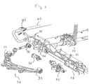
- a piece 50 of an aluminum foundry comprises an upper face 51 which is fixed under the spar 10.
- the upper face 51 comprises a rear part 51a which is fixed at a rear position relative to the tip of the half-cone of the concave depression 12, and a front part 51b coming to be fixed at a front position relative to the point of the half-cone of the concave depression 12.
- the part 50 of the aluminum foundry makes it possible to reinforce the spar 10 under the 'location of the tip of the half-cone formed by the concave depression 12.
- an aluminum casting part 60 comprises an upper face 61 which is fixed under the spar 20 in a symmetrical manner comparable to the casting part 50 of' aluminum to reinforce the spar 20 under the location of the tip of the half-cone formed by the concave depression 22.
- the cradle 30 is more particularly here a rear cradle which comprises a right side beam 31 and a left side beam 32, connected by a rear transverse beam 34 and by a beam front transverse 33.
- the beams 31 to 34 can be made of pressed and bent aluminum. An embodiment of the beams 31 to 34 in the form of aluminum profiles, for example obtained by hot extrusion, provides better mechanical and thermal resistance.
- the front transverse beam 33 protrudes on each side of the cradle to better attach to the central unit of the vehicle.
- the rear transverse beam 34 supports a caliper 37 to which it is secured, for example by screw connection, and to which is fixed a reinforcing tie rod 38 for an engine torque take-up link (not shown).
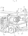
- the aluminum casting part 50 comprises in the lower part a protuberance 52 located at the rear of an inner side face and a protuberance 53 located at the front of the inner side face.
- inner side face is understood to mean any face of the cast part oriented, in other words looking towards the interior of the engine compartment.
- the protuberances 52, 53 can be on lower parts of different levels.
- Each protuberance 52, 53 comprises a surface which is substantially but not necessarily strictly parallel to the upper face 51 of the aluminum casting part 50 and which is drilled substantially in its center to allow the passage of a fixing screw on the upper face of the lateral beam 31.
- the aluminum casting part 60 comprises in lower part a protuberance 62 located at the rear of an inner side face and a protuberance 63 located at the front of the inner side face as can also be seen on the figure 1 .
- the foundry part 50 comprises an opening 54 passing through the inner side face to the outer side face to allow passage of the motor shaft of the powertrain towards the right wheel (not shown). In this way, the foundry part 50 prevents weakening of the spar 10 by a passage of the motor shaft passing through it.
- the opening 54 can be made in tubular form, but this embodiment requires a casting piece high enough to contain the diameter of the tubular form necessary for the passage of the motor shaft.
- the opening 54 is in the form of a semi-cylindrical concave depression formed in the upper face 51 of the foundry part 50.
- the lower face of the spar 10 then comprises a semi-cylindrical concave depression 13 arranged to form a hollow cylinder of sufficient diameter to pass the drive shaft when the semi-cylindrical concave depression 13 is disposed above and facing the opening 54 in the form of a semi-cylindrical concave depression.
- the rear part 51a of the upper face 51 is then fixed in the rear position with respect to the semi-cylindrical concave depression constituting the opening 54, and the front part 51b then comes to be fixed in the front position with respect to the semi-concave depression.
- the part 50 of foundry reinforces with minimal bulk, the location of the spar 10 in which a sufficient opening can be made by concave depression, in combination with that of the foundry part for the passage of the motor shaft, as well as in its close vicinity it is possible make the opening 12, also by concave depression, sufficient for the passage of the shock absorber (not shown) as close as possible to the spar 10.
- the foundry part 60 comprises an opening 64 passing through the inner side face to the outer side face to allow passage of the motor shaft of the powertrain towards the left wheel (not shown).
- each piece of aluminum foundry by die-casting, by taking the necessary well-known measures to avoid the phenomena of shrinkage on cooling and of microbubbles, such as for example by use of a weight.
- each foundry part 50, 60 is obtained by gravity casting of aluminum.
- gravity shell casting allows the use and reuse of a permanent mold.
- the gravity shell casting process makes it possible to obtain particularly remarkable mechanical characteristics of each foundry part 50, 60 by using an appropriate aluminum alloy, in particular an aluminum alloy comprising from 6.5 to 7 , 5% silicon and 0.25 to 0.45% manganese which offers a tensile strength between 285 and 295 MPa.
- an appropriate aluminum alloy in particular an aluminum alloy comprising from 6.5 to 7 , 5% silicon and 0.25 to 0.45% manganese which offers a tensile strength between 285 and 295 MPa.
- the upper face 51, respectively 61 of the part 50, respectively 60, of aluminum foundry, is fixed under the side member 10, respectively 20 by screws 15.
- the lower part or parts 52, 53, respectively 62, 63 of the part 50, respectively 60, of aluminum foundry are fixed to the upper face of the beam 31, respectively 32 of the cradle 30 by screws.
- Steel screws are preferably used for the mechanical characteristics of this metal which are particularly suitable for fixing, previously subjected to a zinc-nickel treatment for their characteristics of making the steel in contact with aluminum compatible.
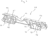
- the part 50 of aluminum casting and likewise symmetrically the part 60 of aluminum casting, comprises a first pair of fins 56 on a side wall to embed one end of the arm or first branch 91 of the suspension triangle .
- the pair of fins 56 emerges perpendicularly to the outer lateral face of the aluminum casting part 50, under the rear part 51a of the upper face 51.
- Each fin is pierced substantially at its center by an opening allowing passage.
- axis or screw 97 for maintaining the arm or first branch 91 of the suspension triangle 90.
- the part 50, and likewise symmetrically the part 60, of aluminum foundry comprises a second pair of fins 57 on said side wall to embed one end of the clamp link 92.
- the part 50, and likewise symmetrically the part 60, of foundry aluminum also comprises on the side wall an interface 58, 59 for fixing the yoke 93.
- the yoke 93 comprises two vertical walls for setting one end of the second branch 94 of the suspension triangle.
- a steel construction of the yoke 93 allows an outward facing upper portion and an inward facing lower portion to be folded. each vertical wall, without loss of mechanical quality, to come to bear respectively against two protuberances 59 and against two vertical flats 58 of the interface to be fixed there by screws.
- part 50 and likewise symmetrically the part 60, of an aluminum foundry comprises an oblique flat 55 on which is fixed a bearing 95 of stabilizer bar 96.
- An embodiment of the bearing 95 in polymer material contributes to the lightening of assembly.
- the foundry part thus makes it possible to integrate interfaces for connecting the vehicle to the ground, in addition to its function as a link between the cradle and the body structure.
Landscapes
- Engineering & Computer Science (AREA)
- Mechanical Engineering (AREA)
- Chemical & Material Sciences (AREA)
- Combustion & Propulsion (AREA)
- Transportation (AREA)
- Architecture (AREA)
- Structural Engineering (AREA)
- Body Structure For Vehicles (AREA)
- Vehicle Body Suspensions (AREA)
- Motor Or Generator Frames (AREA)
Claims (15)
- Anordnung zur Montage eines Hilfsrahmens (30) aus Aluminium eines Fahrzeugs an einer Karosseriestruktur, die wenigstens einen seitlichen Längsträger (10, 20) aus Aluminium umfasst, dadurch gekennzeichnet, dass sie ein Aluminiumgussteil (50, 60) aufweist, das eine unter dem Längsträger (10, 20) befestigte Oberseite (51, 61), einen oder mehrere auf dem Hilfsrahmen (30) befestigte untere Teile (52, 53, 62, 63) und eine Öffnung (54, 64), die einen Durchgang einer Antriebswelle ermöglicht, umfasst.
- Montageanordnung nach Anspruch 1, dadurch gekennzeichnet, dass das Gussteil (50, 60) durch Schwerkraftkokillenguss erhalten wird.
- Montageanordnung nach Anspruch 1 oder 2, dadurch gekennzeichnet, dass das Gussteil (50, 60) aus einer 6,5 bis 7,5 % Silizium und 0,25 bis 0,45 % Mangan umfassenden Aluminiumlegierung besteht, die eine Zugfestigkeit zwischen 285 und 295 MPa aufweist.
- Montageanordnung nach einem der vorhergehenden Ansprüche, dadurch gekennzeichnet, dass die Öffnung (54, 64) die Form einer halbzylinderförmigen konkaven Vertiefung aufweist, die in der Oberseite (51, 61) ausgebildet ist.
- Montageanordnung nach einem der vorhergehenden Ansprüche, dadurch gekennzeichnet, dass die Oberseite (51, 61) des Aluminiumgussteils (50, 60) unter dem Längsträger (10, 20) mit Schrauben (15) befestigt ist.
- Montageanordnung nach einem der vorhergehenden Ansprüche, dadurch gekennzeichnet, dass die unteren Teile (52, 53, 62, 63) des Aluminiumgussteils (50, 60) auf dem Hilfsrahmen (30) mit Schrauben befestigt sind.
- Montageanordnung nach einem der vorhergehenden Ansprüche, dadurch gekennzeichnet, dass das Aluminiumgussteil (50, 60) an einer Seitenwand ein erstes Paar Flügel (56) zum Einpassen eines Endes eines Armes oder eines ersten Schenkels (91) eines Dreieckslenkers umfasst.
- Montageanordnung nach dem vorhergehenden Anspruch, dadurch gekennzeichnet, dass das Aluminiumgussteil (50, 60) an der Seitenwand ein zweites Paar Flügel (57) zum Einpassen eines Endes einer Spurstange (92) .
- Montageanordnung nach einem der Ansprüche 7 oder 8, dadurch gekennzeichnet, dass das Aluminiumgussteil (50, 60) an der Seitenwand eine Verbindungsstelle (58, 59) zur Befestigung eines Gabelstücks (93) zum Einpassen eines Endes eines zweiten Schenkels (94) eines Dreieckslenkers umfasst.
- Montageanordnung nach dem vorhergehenden Anspruch, dadurch gekennzeichnet, dass das Gabelstück (93) aus Stahl besteht.
- Montageanordnung nach dem vorhergehenden Anspruch, dadurch gekennzeichnet, dass das Aluminiumgussteil (50, 60) eine Abflachung (59) umfasst, an welcher ein Lager (95) einer Stabilisatorstange (96) befestigt ist.
- Montageanordnung nach dem vorhergehenden Anspruch, dadurch gekennzeichnet, dass das Lager (95) aus Polymermaterial besteht.
- Montageanordnung nach einem der vorhergehenden Ansprüche, dadurch gekennzeichnet, dass sie einen Bügel (37) umfasst, der mit einem Querträger des Hilfsrahmens (30) fest verbunden ist und an dem ein Verstärkungsstab für eine Drehmomentstütze befestigt ist.
- Montageanordnung nach einem der vorhergehenden Ansprüche, dadurch gekennzeichnet, dass die Karosseriestruktur einen rechten seitlichen Längsträger (10) und einen linken seitlichen Längsträger (20) umfasst, die an ein jeweiliges Ende eines mittleren Querträgers (42) angeschweißt sind.
- Montageanordnung nach Anspruch 14, dadurch gekennzeichnet, dass der rechte seitliche Längsträger (10), der linke seitliche Längsträger (20) und der mittlere Querträger (42) warm stranggepresste Aluminiumprofile sind.
Applications Claiming Priority (2)
| Application Number | Priority Date | Filing Date | Title |
|---|---|---|---|
| FR1661986A FR3059630B1 (fr) | 2016-12-06 | 2016-12-06 | Assemblage d'un berceau de vehicule sur caisse comportant une piece de fonderie |
| PCT/EP2017/080754 WO2018104119A1 (fr) | 2016-12-06 | 2017-11-29 | Assemblage d'un berceau de véhicule sur caisse comportant une pièce de fonderie |
Publications (2)
| Publication Number | Publication Date |
|---|---|
| EP3551522A1 EP3551522A1 (de) | 2019-10-16 |
| EP3551522B1 true EP3551522B1 (de) | 2020-12-30 |
Family
ID=58228201
Family Applications (1)
| Application Number | Title | Priority Date | Filing Date |
|---|---|---|---|
| EP17803972.3A Active EP3551522B1 (de) | 2016-12-06 | 2017-11-29 | Montage einer fahrzeughalterung an einer karosserie mit einem gussteil |
Country Status (7)
| Country | Link |
|---|---|
| US (1) | US20190337567A1 (de) |
| EP (1) | EP3551522B1 (de) |
| JP (1) | JP7041153B2 (de) |
| KR (1) | KR102277049B1 (de) |
| CN (1) | CN109982916B (de) |
| FR (1) | FR3059630B1 (de) |
| WO (1) | WO2018104119A1 (de) |
Families Citing this family (2)
| Publication number | Priority date | Publication date | Assignee | Title |
|---|---|---|---|---|
| RU2656929C2 (ru) * | 2014-03-31 | 2018-06-07 | Йорозу Корпорейшн | Элемент подвески и способ его изготовления |
| US10960518B1 (en) * | 2019-09-20 | 2021-03-30 | Anthony M. Barraco | Inserts for shielding aluminum vehicles from clamps |
Family Cites Families (15)
| Publication number | Priority date | Publication date | Assignee | Title |
|---|---|---|---|---|
| US5879026A (en) * | 1995-12-19 | 1999-03-09 | Chrysler Corporation | Vehicle suspension and steering cradle |
| US5947519A (en) * | 1998-03-06 | 1999-09-07 | Chrysler Corporation | Extruded node for vehicle frame |
| JP3921314B2 (ja) * | 1999-09-03 | 2007-05-30 | 株式会社神戸製鋼所 | 衝撃破壊強度に優れたアルミニウム合金鋳造材およびその製造方法 |
| US6866295B2 (en) * | 2000-12-28 | 2005-03-15 | Dana Corporation | Modular cast independent front suspension subframe |
| GB0319491D0 (en) * | 2003-08-20 | 2003-09-17 | Ford Global Tech Llc | Bonded structural joints |
| DE102004062932B4 (de) * | 2004-12-28 | 2018-09-06 | Volkswagen Ag | Hintere Bodenstruktur eines Kraftfahrzeugs |
| US20100133773A1 (en) * | 2005-09-09 | 2010-06-03 | Thomas Buschjohann | Axle Support |
| WO2007031059A2 (de) | 2005-09-13 | 2007-03-22 | Ksm Castings Gmbh | Hilfsrahmen, insbesondere für kraftfahrzeuge |
| DE102006013548C5 (de) * | 2006-03-24 | 2018-01-18 | Audi Ag | Als Fahrschemel ausgebildeter Hilfsrahmen für Kraftfahrzeuge sowie Fahrzeugkarosserie |
| JP4994734B2 (ja) * | 2006-07-24 | 2012-08-08 | 株式会社大紀アルミニウム工業所 | 鋳造用アルミニウム合金および同アルミニウム合金鋳物 |
| JP5561846B2 (ja) * | 2006-12-13 | 2014-07-30 | 株式会社Uacj押出加工 | 高強度アルミニウム合金材およびその製造方法 |
| DE102011106619A1 (de) * | 2011-06-16 | 2012-12-20 | GM Global Technology Operations LLC (n. d. Gesetzen des Staates Delaware) | Vorderachssystem für ein Fahrzeug und Kraftfahrzeug |
| FR3000009B1 (fr) * | 2012-12-20 | 2018-08-03 | Renault S.A.S. | Dispositif de liaison d'un berceau automobile |
| WO2014097513A1 (ja) * | 2012-12-21 | 2014-06-26 | 本田技研工業株式会社 | 車体構造 |
| JP5983400B2 (ja) * | 2012-12-28 | 2016-08-31 | マツダ株式会社 | 前部車体構造 |
-
2016
- 2016-12-06 FR FR1661986A patent/FR3059630B1/fr not_active Expired - Fee Related
-
2017
- 2017-11-29 WO PCT/EP2017/080754 patent/WO2018104119A1/fr not_active Ceased
- 2017-11-29 KR KR1020197016338A patent/KR102277049B1/ko active Active
- 2017-11-29 US US16/462,096 patent/US20190337567A1/en not_active Abandoned
- 2017-11-29 JP JP2019530077A patent/JP7041153B2/ja active Active
- 2017-11-29 CN CN201780072021.6A patent/CN109982916B/zh active Active
- 2017-11-29 EP EP17803972.3A patent/EP3551522B1/de active Active
Non-Patent Citations (1)
| Title |
|---|
| None * |
Also Published As
| Publication number | Publication date |
|---|---|
| CN109982916B (zh) | 2022-07-22 |
| EP3551522A1 (de) | 2019-10-16 |
| JP2019535589A (ja) | 2019-12-12 |
| KR20190092424A (ko) | 2019-08-07 |
| US20190337567A1 (en) | 2019-11-07 |
| FR3059630B1 (fr) | 2020-02-14 |
| FR3059630A1 (fr) | 2018-06-08 |
| JP7041153B2 (ja) | 2022-03-23 |
| WO2018104119A1 (fr) | 2018-06-14 |
| CN109982916A (zh) | 2019-07-05 |
| KR102277049B1 (ko) | 2021-07-13 |
Similar Documents
| Publication | Publication Date | Title |
|---|---|---|
| EP3551484B1 (de) | Verbindungsvorrichtung zwischen einer aluminiumseitenleiste eines fahrzeugs und eines querlenkers | |
| EP3003826B1 (de) | Träger für fahrwerk eines kraftfahrzeugs | |
| EP3551522B1 (de) | Montage einer fahrzeughalterung an einer karosserie mit einem gussteil | |
| FR2550155A1 (de) | ||
| FR2986489A1 (fr) | Berceau moteur monobloc extrude | |
| EP2436579A2 (de) | Querträgergruppe eines Armaturenbrettes für ein Auto | |
| EP3119665B1 (de) | Heckstruktur eines kraftfahrzeugs | |
| EP4124478A1 (de) | Lenker oder dreieckslenker und verfahren zur herstellung eines solchen lenkers oder dreieckslenkers | |
| EP3204247B1 (de) | Aufhängungslenker für ein fahrzeug | |
| EP3386845B1 (de) | Kraftfahrzeugkarosserieelement und zugehöriges verfahren zur herstellung | |
| EP2358578A1 (de) | Einen vorbaurahmen und einen gebogenen träger enthaltende anordnung und fahrzeug mit solch einer anordnung | |
| FR3139783A1 (fr) | extension de longeronnet arrière pour véhicule automobile | |
| FR3044601A1 (fr) | "essieu arriere de vehicule automobile comportant des moyens de retenue pour ameliorer la liaison par collage d'une traverse en materiau composite avec les bras" | |
| EP3333050B1 (de) | Befestigung mit halbschalen eines querträgers einer fahrerkabine eines kraftfahrzeugs | |
| FR3080348A1 (fr) | Structure de caisse d'un vehicule automobile comprenant un agencement de renfort en extremite de longeron. | |
| FR3167074A1 (fr) | Fixation de rotule sur un bras de suspension de véhicule automobile | |
| FR2874574A1 (fr) | Chassis pour motoquad et motoquad correspondant | |
| WO2022258899A1 (fr) | Structure de caisse de véhicule automobile | |
| FR3030431A1 (fr) | Nœud de structure avant d'un vehicule automobile. | |
| FR3027865A1 (fr) | Custode pour vehicule automobile et procede de formage par fonderie d'une telle piece | |
| FR2836885A1 (fr) | Element de structure et structure arriere d'un vehicule automobile, procede de fabrication d'une telle structure |
Legal Events
| Date | Code | Title | Description |
|---|---|---|---|
| STAA | Information on the status of an ep patent application or granted ep patent |
Free format text: STATUS: UNKNOWN |
|
| STAA | Information on the status of an ep patent application or granted ep patent |
Free format text: STATUS: THE INTERNATIONAL PUBLICATION HAS BEEN MADE |
|
| PUAI | Public reference made under article 153(3) epc to a published international application that has entered the european phase |
Free format text: ORIGINAL CODE: 0009012 |
|
| STAA | Information on the status of an ep patent application or granted ep patent |
Free format text: STATUS: REQUEST FOR EXAMINATION WAS MADE |
|
| 17P | Request for examination filed |
Effective date: 20190520 |
|
| AK | Designated contracting states |
Kind code of ref document: A1 Designated state(s): AL AT BE BG CH CY CZ DE DK EE ES FI FR GB GR HR HU IE IS IT LI LT LU LV MC MK MT NL NO PL PT RO RS SE SI SK SM TR |
|
| AX | Request for extension of the european patent |
Extension state: BA ME |
|
| DAV | Request for validation of the european patent (deleted) | ||
| DAX | Request for extension of the european patent (deleted) | ||
| GRAP | Despatch of communication of intention to grant a patent |
Free format text: ORIGINAL CODE: EPIDOSNIGR1 |
|
| STAA | Information on the status of an ep patent application or granted ep patent |
Free format text: STATUS: GRANT OF PATENT IS INTENDED |
|
| INTG | Intention to grant announced |
Effective date: 20200707 |
|
| GRAS | Grant fee paid |
Free format text: ORIGINAL CODE: EPIDOSNIGR3 |
|
| GRAA | (expected) grant |
Free format text: ORIGINAL CODE: 0009210 |
|
| STAA | Information on the status of an ep patent application or granted ep patent |
Free format text: STATUS: THE PATENT HAS BEEN GRANTED |
|
| AK | Designated contracting states |
Kind code of ref document: B1 Designated state(s): AL AT BE BG CH CY CZ DE DK EE ES FI FR GB GR HR HU IE IS IT LI LT LU LV MC MK MT NL NO PL PT RO RS SE SI SK SM TR |
|
| REG | Reference to a national code |
Ref country code: GB Ref legal event code: FG4D Free format text: NOT ENGLISH |
|
| REG | Reference to a national code |
Ref country code: AT Ref legal event code: REF Ref document number: 1349672 Country of ref document: AT Kind code of ref document: T Effective date: 20210115 |
|
| REG | Reference to a national code |
Ref country code: DE Ref legal event code: R096 Ref document number: 602017030620 Country of ref document: DE |
|
| REG | Reference to a national code |
Ref country code: IE Ref legal event code: FG4D Free format text: LANGUAGE OF EP DOCUMENT: FRENCH |
|
| PG25 | Lapsed in a contracting state [announced via postgrant information from national office to epo] |
Ref country code: NO Free format text: LAPSE BECAUSE OF FAILURE TO SUBMIT A TRANSLATION OF THE DESCRIPTION OR TO PAY THE FEE WITHIN THE PRESCRIBED TIME-LIMIT Effective date: 20210330 Ref country code: GR Free format text: LAPSE BECAUSE OF FAILURE TO SUBMIT A TRANSLATION OF THE DESCRIPTION OR TO PAY THE FEE WITHIN THE PRESCRIBED TIME-LIMIT Effective date: 20210331 Ref country code: RS Free format text: LAPSE BECAUSE OF FAILURE TO SUBMIT A TRANSLATION OF THE DESCRIPTION OR TO PAY THE FEE WITHIN THE PRESCRIBED TIME-LIMIT Effective date: 20201230 Ref country code: FI Free format text: LAPSE BECAUSE OF FAILURE TO SUBMIT A TRANSLATION OF THE DESCRIPTION OR TO PAY THE FEE WITHIN THE PRESCRIBED TIME-LIMIT Effective date: 20201230 |
|
| REG | Reference to a national code |
Ref country code: AT Ref legal event code: MK05 Ref document number: 1349672 Country of ref document: AT Kind code of ref document: T Effective date: 20201230 |
|
| PG25 | Lapsed in a contracting state [announced via postgrant information from national office to epo] |
Ref country code: SE Free format text: LAPSE BECAUSE OF FAILURE TO SUBMIT A TRANSLATION OF THE DESCRIPTION OR TO PAY THE FEE WITHIN THE PRESCRIBED TIME-LIMIT Effective date: 20201230 Ref country code: LV Free format text: LAPSE BECAUSE OF FAILURE TO SUBMIT A TRANSLATION OF THE DESCRIPTION OR TO PAY THE FEE WITHIN THE PRESCRIBED TIME-LIMIT Effective date: 20201230 Ref country code: BG Free format text: LAPSE BECAUSE OF FAILURE TO SUBMIT A TRANSLATION OF THE DESCRIPTION OR TO PAY THE FEE WITHIN THE PRESCRIBED TIME-LIMIT Effective date: 20210330 |
|
| REG | Reference to a national code |
Ref country code: NL Ref legal event code: MP Effective date: 20201230 |
|
| PG25 | Lapsed in a contracting state [announced via postgrant information from national office to epo] |
Ref country code: HR Free format text: LAPSE BECAUSE OF FAILURE TO SUBMIT A TRANSLATION OF THE DESCRIPTION OR TO PAY THE FEE WITHIN THE PRESCRIBED TIME-LIMIT Effective date: 20201230 |
|
| REG | Reference to a national code |
Ref country code: LT Ref legal event code: MG9D |
|
| PG25 | Lapsed in a contracting state [announced via postgrant information from national office to epo] |
Ref country code: PT Free format text: LAPSE BECAUSE OF FAILURE TO SUBMIT A TRANSLATION OF THE DESCRIPTION OR TO PAY THE FEE WITHIN THE PRESCRIBED TIME-LIMIT Effective date: 20210430 Ref country code: RO Free format text: LAPSE BECAUSE OF FAILURE TO SUBMIT A TRANSLATION OF THE DESCRIPTION OR TO PAY THE FEE WITHIN THE PRESCRIBED TIME-LIMIT Effective date: 20201230 Ref country code: SK Free format text: LAPSE BECAUSE OF FAILURE TO SUBMIT A TRANSLATION OF THE DESCRIPTION OR TO PAY THE FEE WITHIN THE PRESCRIBED TIME-LIMIT Effective date: 20201230 Ref country code: EE Free format text: LAPSE BECAUSE OF FAILURE TO SUBMIT A TRANSLATION OF THE DESCRIPTION OR TO PAY THE FEE WITHIN THE PRESCRIBED TIME-LIMIT Effective date: 20201230 Ref country code: CZ Free format text: LAPSE BECAUSE OF FAILURE TO SUBMIT A TRANSLATION OF THE DESCRIPTION OR TO PAY THE FEE WITHIN THE PRESCRIBED TIME-LIMIT Effective date: 20201230 Ref country code: LT Free format text: LAPSE BECAUSE OF FAILURE TO SUBMIT A TRANSLATION OF THE DESCRIPTION OR TO PAY THE FEE WITHIN THE PRESCRIBED TIME-LIMIT Effective date: 20201230 |
|
| PG25 | Lapsed in a contracting state [announced via postgrant information from national office to epo] |
Ref country code: AT Free format text: LAPSE BECAUSE OF FAILURE TO SUBMIT A TRANSLATION OF THE DESCRIPTION OR TO PAY THE FEE WITHIN THE PRESCRIBED TIME-LIMIT Effective date: 20201230 Ref country code: PL Free format text: LAPSE BECAUSE OF FAILURE TO SUBMIT A TRANSLATION OF THE DESCRIPTION OR TO PAY THE FEE WITHIN THE PRESCRIBED TIME-LIMIT Effective date: 20201230 |
|
| PG25 | Lapsed in a contracting state [announced via postgrant information from national office to epo] |
Ref country code: IS Free format text: LAPSE BECAUSE OF FAILURE TO SUBMIT A TRANSLATION OF THE DESCRIPTION OR TO PAY THE FEE WITHIN THE PRESCRIBED TIME-LIMIT Effective date: 20210430 |
|
| REG | Reference to a national code |
Ref country code: DE Ref legal event code: R097 Ref document number: 602017030620 Country of ref document: DE |
|
| PG25 | Lapsed in a contracting state [announced via postgrant information from national office to epo] |
Ref country code: IT Free format text: LAPSE BECAUSE OF FAILURE TO SUBMIT A TRANSLATION OF THE DESCRIPTION OR TO PAY THE FEE WITHIN THE PRESCRIBED TIME-LIMIT Effective date: 20201230 Ref country code: AL Free format text: LAPSE BECAUSE OF FAILURE TO SUBMIT A TRANSLATION OF THE DESCRIPTION OR TO PAY THE FEE WITHIN THE PRESCRIBED TIME-LIMIT Effective date: 20201230 |
|
| PLBE | No opposition filed within time limit |
Free format text: ORIGINAL CODE: 0009261 |
|
| STAA | Information on the status of an ep patent application or granted ep patent |
Free format text: STATUS: NO OPPOSITION FILED WITHIN TIME LIMIT |
|
| PG25 | Lapsed in a contracting state [announced via postgrant information from national office to epo] |
Ref country code: DK Free format text: LAPSE BECAUSE OF FAILURE TO SUBMIT A TRANSLATION OF THE DESCRIPTION OR TO PAY THE FEE WITHIN THE PRESCRIBED TIME-LIMIT Effective date: 20201230 |
|
| 26N | No opposition filed |
Effective date: 20211001 |
|
| PG25 | Lapsed in a contracting state [announced via postgrant information from national office to epo] |
Ref country code: ES Free format text: LAPSE BECAUSE OF FAILURE TO SUBMIT A TRANSLATION OF THE DESCRIPTION OR TO PAY THE FEE WITHIN THE PRESCRIBED TIME-LIMIT Effective date: 20201230 |
|
| PG25 | Lapsed in a contracting state [announced via postgrant information from national office to epo] |
Ref country code: SI Free format text: LAPSE BECAUSE OF FAILURE TO SUBMIT A TRANSLATION OF THE DESCRIPTION OR TO PAY THE FEE WITHIN THE PRESCRIBED TIME-LIMIT Effective date: 20201230 |
|
| PG25 | Lapsed in a contracting state [announced via postgrant information from national office to epo] |
Ref country code: IS Free format text: LAPSE BECAUSE OF FAILURE TO SUBMIT A TRANSLATION OF THE DESCRIPTION OR TO PAY THE FEE WITHIN THE PRESCRIBED TIME-LIMIT Effective date: 20210430 |
|
| PG25 | Lapsed in a contracting state [announced via postgrant information from national office to epo] |
Ref country code: MC Free format text: LAPSE BECAUSE OF FAILURE TO SUBMIT A TRANSLATION OF THE DESCRIPTION OR TO PAY THE FEE WITHIN THE PRESCRIBED TIME-LIMIT Effective date: 20201230 |
|
| REG | Reference to a national code |
Ref country code: CH Ref legal event code: PL |
|
| PG25 | Lapsed in a contracting state [announced via postgrant information from national office to epo] |
Ref country code: LU Free format text: LAPSE BECAUSE OF NON-PAYMENT OF DUE FEES Effective date: 20211129 Ref country code: BE Free format text: LAPSE BECAUSE OF NON-PAYMENT OF DUE FEES Effective date: 20211130 |
|
| REG | Reference to a national code |
Ref country code: BE Ref legal event code: MM Effective date: 20211130 |
|
| PG25 | Lapsed in a contracting state [announced via postgrant information from national office to epo] |
Ref country code: LI Free format text: LAPSE BECAUSE OF NON-PAYMENT OF DUE FEES Effective date: 20211130 Ref country code: CH Free format text: LAPSE BECAUSE OF NON-PAYMENT OF DUE FEES Effective date: 20211130 |
|
| PG25 | Lapsed in a contracting state [announced via postgrant information from national office to epo] |
Ref country code: IE Free format text: LAPSE BECAUSE OF NON-PAYMENT OF DUE FEES Effective date: 20211129 |
|
| PG25 | Lapsed in a contracting state [announced via postgrant information from national office to epo] |
Ref country code: NL Free format text: LAPSE BECAUSE OF NON-PAYMENT OF DUE FEES Effective date: 20201230 Ref country code: CY Free format text: LAPSE BECAUSE OF FAILURE TO SUBMIT A TRANSLATION OF THE DESCRIPTION OR TO PAY THE FEE WITHIN THE PRESCRIBED TIME-LIMIT Effective date: 20201230 |
|
| P01 | Opt-out of the competence of the unified patent court (upc) registered |
Effective date: 20230608 |
|
| PG25 | Lapsed in a contracting state [announced via postgrant information from national office to epo] |
Ref country code: SM Free format text: LAPSE BECAUSE OF FAILURE TO SUBMIT A TRANSLATION OF THE DESCRIPTION OR TO PAY THE FEE WITHIN THE PRESCRIBED TIME-LIMIT Effective date: 20201230 Ref country code: HU Free format text: LAPSE BECAUSE OF FAILURE TO SUBMIT A TRANSLATION OF THE DESCRIPTION OR TO PAY THE FEE WITHIN THE PRESCRIBED TIME-LIMIT; INVALID AB INITIO Effective date: 20171129 |
|
| PG25 | Lapsed in a contracting state [announced via postgrant information from national office to epo] |
Ref country code: MK Free format text: LAPSE BECAUSE OF FAILURE TO SUBMIT A TRANSLATION OF THE DESCRIPTION OR TO PAY THE FEE WITHIN THE PRESCRIBED TIME-LIMIT Effective date: 20201230 |
|
| PG25 | Lapsed in a contracting state [announced via postgrant information from national office to epo] |
Ref country code: TR Free format text: LAPSE BECAUSE OF FAILURE TO SUBMIT A TRANSLATION OF THE DESCRIPTION OR TO PAY THE FEE WITHIN THE PRESCRIBED TIME-LIMIT Effective date: 20201230 |
|
| PG25 | Lapsed in a contracting state [announced via postgrant information from national office to epo] |
Ref country code: MT Free format text: LAPSE BECAUSE OF FAILURE TO SUBMIT A TRANSLATION OF THE DESCRIPTION OR TO PAY THE FEE WITHIN THE PRESCRIBED TIME-LIMIT Effective date: 20201230 |
|
| PGFP | Annual fee paid to national office [announced via postgrant information from national office to epo] |
Ref country code: DE Payment date: 20251119 Year of fee payment: 9 |
|
| PGFP | Annual fee paid to national office [announced via postgrant information from national office to epo] |
Ref country code: GB Payment date: 20251121 Year of fee payment: 9 |
|
| PGFP | Annual fee paid to national office [announced via postgrant information from national office to epo] |
Ref country code: FR Payment date: 20251126 Year of fee payment: 9 |