EP3551382B1 - Staubhaube für ein schleifgerät - Google Patents
Staubhaube für ein schleifgerät Download PDFInfo
- Publication number
- EP3551382B1 EP3551382B1 EP17808813.4A EP17808813A EP3551382B1 EP 3551382 B1 EP3551382 B1 EP 3551382B1 EP 17808813 A EP17808813 A EP 17808813A EP 3551382 B1 EP3551382 B1 EP 3551382B1
- Authority
- EP
- European Patent Office
- Prior art keywords
- hood
- sector
- web
- dust hood
- dust
- Prior art date
- Legal status (The legal status is an assumption and is not a legal conclusion. Google has not performed a legal analysis and makes no representation as to the accuracy of the status listed.)
- Active
Links
Images

Classifications
-
- B—PERFORMING OPERATIONS; TRANSPORTING
- B24—GRINDING; POLISHING
- B24B—MACHINES, DEVICES, OR PROCESSES FOR GRINDING OR POLISHING; DRESSING OR CONDITIONING OF ABRADING SURFACES; FEEDING OF GRINDING, POLISHING, OR LAPPING AGENTS
- B24B55/00—Safety devices for grinding or polishing machines; Accessories fitted to grinding or polishing machines for keeping tools or parts of the machine in good working condition
- B24B55/06—Dust extraction equipment on grinding or polishing machines
- B24B55/10—Dust extraction equipment on grinding or polishing machines specially designed for portable grinding machines, e.g. hand-guided
- B24B55/102—Dust extraction equipment on grinding or polishing machines specially designed for portable grinding machines, e.g. hand-guided with rotating tools
-
- B—PERFORMING OPERATIONS; TRANSPORTING
- B24—GRINDING; POLISHING
- B24B—MACHINES, DEVICES, OR PROCESSES FOR GRINDING OR POLISHING; DRESSING OR CONDITIONING OF ABRADING SURFACES; FEEDING OF GRINDING, POLISHING, OR LAPPING AGENTS
- B24B23/00—Portable grinding machines, e.g. hand-guided; Accessories therefor
- B24B23/02—Portable grinding machines, e.g. hand-guided; Accessories therefor with rotating grinding tools; Accessories therefor
- B24B23/028—Angle tools
-
- B—PERFORMING OPERATIONS; TRANSPORTING
- B24—GRINDING; POLISHING
- B24B—MACHINES, DEVICES, OR PROCESSES FOR GRINDING OR POLISHING; DRESSING OR CONDITIONING OF ABRADING SURFACES; FEEDING OF GRINDING, POLISHING, OR LAPPING AGENTS
- B24B55/00—Safety devices for grinding or polishing machines; Accessories fitted to grinding or polishing machines for keeping tools or parts of the machine in good working condition
- B24B55/04—Protective covers for the grinding wheel
- B24B55/05—Protective covers for the grinding wheel specially designed for portable grinding machines
- B24B55/052—Protective covers for the grinding wheel specially designed for portable grinding machines with rotating tools
Definitions
- the present invention relates to a dust hood for a grinding device equipped with a gear neck for fastening the dust hood.
- the dust hood is equipped with a hood body to cover a major part of the grinding wheel on one side.
- the dust hood has a hood sector which is displaceable in the circumferential direction of the hood body and which is provided for gradually covering and releasing a remaining part of the grinding wheel as required.
- the dust hood has a suction connection which can be used to extract any subsurface material from the hood body.
- a web is provided between the hood body and the hood sector which at least partially separates a main chamber defined by the hood body from a segment chamber defined by the hood sector.
- Dust hoods of the type mentioned are basically known from the prior art, see for example document DE102012001925 A1 which discloses the preamble of claim 1. They serve to prevent the spread of dust during grinding work in order to protect the health of a user of the grinding device.
- the invention is achieved in that the web has a web opening through which air can flow from the segment chamber into the main chamber.
- the invention includes the knowledge that in the case of dust hoods of the prior art, more precisely in their displaceable hood sectors, there is too little negative pressure in the suction operation and thus the hood sector is not “flushed” enough. This is particularly the case when the hood body or the hood sector is sealed off from the surroundings by a comparatively tight curtain, for example a brush curtain. It has been observed that this prevents an optimal flow in the movable or rotatable hood sector.
- the web has at least one web opening through which air can flow from the segment chamber into the main chamber.
- the suction connection is connected to the hood body via a connection socket.
- the connection socket is preferably oriented tangentially to the grinding wheel and / or the connection socket defines a suction channel running tangentially to the grinding wheel. It has been found to be advantageous if the web opening formed on the web is aligned with the connection socket. Such an alignment can lie in a wheel plane of the grinding wheel or a plane parallel to it.
- the web has an overall length and the third of the total length closest to the connection socket has one or more web openings. It is particularly advantageous if the web has a total length and only the third of the total length closest to the connection socket has one or more web openings.
- a sector opening is formed in a surface of the hood sector, through which the ambient air can flow into the segment chamber.
- This surface of the hood sector is preferably oriented perpendicular to the axis of rotation of the grinding wheel, in other words a surface normal of the surface of the hood sector is preferably parallel to the axis of rotation of the grinding wheel. It was recognized that by providing one or more sector openings in the surface of the hood sector, in particular the surface of the hood sector facing the grinding device, flushing of the hood sector and, immediately afterwards, the hood body can be further improved.
- the web opening formed in the web and the sector opening formed in the hood sector act with one another in a synergetic manner.
- the sector opening is particularly preferably arranged to the right of a connection socket of the suction connection, based on the direction of rotation of the grinding wheel and from the point of view of the grinding device.
- the hood sector has an outer sector length which, starting from the axis of rotation of the grinding wheel, defines a sector of a circle, the sector opening being located in one third, preferably only in the third of the sector of the circle that is the greatest distance from the connection base.
- a minimum distance between the sector opening and the axis of rotation of the grinding wheel can be greater than four fifths of the largest diameter of the hood body.
- the web extends vertically in the direction of the axis of rotation of the grinding wheel.
- the web can predominantly be located on the side of the grinding wheel facing the grinding device.
- the web is particularly preferably fixed to the hood body.
- the web can be stationary in relation to the displaceable hood sector. Both a web on the hood body and a corresponding web on the hood sector can be provided.
- At least one passage opening is formed in a surface of the hood body facing the grinding device, through which the ambient air can flow into the hood body.
- the through-opening is preferably arranged to the right of a connection socket of the suction connection, based on the direction of rotation of the grinding wheel and from the point of view of the grinding device.
- the dust hood is equipped with a curtain running along a circumference of the hood body for sealing the hood body at least in sections against a substrate to be processed by means of the grinding wheel.
- a curtain can also be provided in the hood sector.
- the curtain and / or the curtains are preferably designed as brush curtains.
- the object is also achieved by a grinding device with a gear neck and with a dust hood of the type described above, the dust hood being or to be arranged on the gear neck.
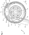
- FIG Fig. 1 A preferred embodiment of a dust hood 100 according to the invention is shown in FIG Fig. 1 shown.
- the dust hood 100 is equipped with a hood body 10 for covering a predominant part of a grinding wheel on one side (see the indicated grinding wheel 220 in FIG Fig. 3 ).
- the dust hood 100 has a hood sector 20 which is displaceable, more precisely rotatable, in the circumferential direction U of the hood body 10 along the hood body 10. If necessary, a remaining part of the grinding wheel can be gradually covered and / or released by means of the hood sector 20.
- the dust hood 100 has a suction connection 40, via which a subsurface material can be extracted from the hood body 10. Between the hood body 10 and the hood sector 20, a web 50 is provided which at least partially separates a main chamber 15 defined by the hood body 10 from a segment chamber 25 which is defined by the hood sector 20.
- three web openings 55 are formed in the web 50 (see also FIG Fig. 2 ) can flow into the main chamber 15 via the air L from the segment chamber 25.
- the suction connection 40 is connected to the hood body 10 via a connection base 45 which is oriented in the tangential direction T to the grinding wheel.
- the web openings 55 are aligned with the connection base 45.
- alignment means, on the one hand, that the web openings 55 themselves are located in a tangential alignment, viewed from the connection base 45.
- this particular is off Fig. 2
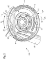
- the shape of the web openings 55 within the web 50 itself can be clearly seen in alignment with the tangentially extending connection socket 45. In FIG Fig. 2 The illustrated embodiment, the flanks of the web openings at an angle of approximately 45 degrees.
- Fig. 1 It can again be clearly seen that the web 50 intersects the hood body 10 in the sense of a secant.
- the web 50 has an overall length GL. Only in the third 1/3 GL closest to the connection socket 45 are there exactly three web openings.
- hood sector 20 In the hood sector 20 (in the upper area of the Fig. 1 ) three sector openings 23 can be seen, which are located in a surface OS (cf. Fig. 4 ) of the hood sector 20 are formed. Ambient air UL can flow into the segment chamber 25 via these sector openings 23.
- Fig. 2 illustrated embodiment are those with reference to Fig. 1
- the web openings 55 described, through which air L can flow from the segment chamber 25 into the main chamber 15, can be seen particularly well.
- the dust hood 100 of the Fig. 2 is equipped with a curtain 30 running along a circumference U of the hood body 10 for at least partially sealing off the hood body 10 against a substrate to be processed by means of the grinding wheel.
- a curtain 30 ' is also provided in the hood sector 20.
- the curtains 30, 30 ' are designed as brush curtains.
- the illustrated embodiment are in a surface OF the hood body facing the grinding device (in Fig. 2 shown in dashed lines, since five through openings 13 are formed on the rear side, through which ambient air UL can flow into the hood body 10. These through openings 13 ensure additional air pressure equalization within the dust hood.
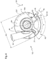
- Fig. 3 now shows the dust hood 100 of Fig. 1 , which is arranged on a grinding device 200 (shown schematically).
- the grinding device 200 has a gear neck 210 for fastening the dust hood 100.
- the grinding wheel 220 indicated schematically here is set in rotation via the drive spindle 230, specifically in the direction of rotation DR about the axis of rotation R of the grinding wheel 220.
- the web 50 extends vertically in the direction of the axis of rotation R of the grinding wheel 220.
- the web 50 is predominantly located on the side ZS of the grinding wheel 220 facing the grinding device 200.
- a step 59 formed in the vertical web 50 a remaining part of the grinding wheel 220 can be moved over the web 50 into the displaceable hood sector 20, which for reasons of clarity in FIG Fig. 3 is not shown, protrude.
- Fig. 4 can also be removed, the sector openings 23, based on the direction of rotation DR of the grinding wheel and from the perspective of the grinding device, are arranged to the right of the connection socket 45 of the suction connection 40.
- the hood sector 20 has an outer sector length SL which, starting from the axis of rotation R of the grinding wheel 220 (in Fig. 4 indicated by the arcuate dash-dot line) defines a circular sector KS.
- the three sector openings 23 are only located in the third of the circular sector KS which, in total, has the greatest distance from the connection base 45. In the exemplary embodiment shown here, this is the right third, a third KS, which is approximately opposite the connection socket 45.
- a minimum distance MA between the sector opening 23 and the axis of rotation R of the grinding wheel 220 is greater than approximately four fifths of the largest diameter GD of the hood body 10.
Landscapes
- Engineering & Computer Science (AREA)
- Mechanical Engineering (AREA)
- Grinding-Machine Dressing And Accessory Apparatuses (AREA)
- Finish Polishing, Edge Sharpening, And Grinding By Specific Grinding Devices (AREA)
Description
- Die vorliegende Erfindung betrifft eine Staubhaube für ein mit einem Getriebehals zur Befestigung der Staubhaube ausgestatteten Schleifgerät. Die Staubhaube ist ausgestattet mit einem Haubenkörper zum einseitigen Abdecken eines überwiegenden Teils der Schleifscheibe. Die Staubhaube weist einen in Umfangsrichtung des Haubenkörpers entlang des Haubenkörpers verschiebbaren Haubensektor auf, der zum bedarfsweisen graduellen Abdecken und Freigeben eines verbleibenden Teils der Schleifscheibe vorgesehen ist. Die Staubhaube verfügt über einen Absauganschluss über den ein Untergrundabtrag aus dem Haubenkörper abgesaugt werden kann. Zwischen dem Haubenkörper und dem Haubensektor ist ein Steg vorgesehen, der eine durch den Haubenkörper definierte Hauptkammer zumindest teilweise von einer Segmentkammer, die durch den Haubensektor definiert ist, trennt.
- Staubhauben der eingangs genannten Art sind grundsätzlich aus dem Stand der Technik bekannt, siehe z.B. Dokument
DE102012001925 A1 , das den Oberbegriff des Anspruchs 1 offenbart. Sie dienen der Vermeidung einer Staubausbreitung bei Schleifarbeiten, um die Gesundheit eines Benutzers des Schleifgeräts zu schützen. - Es ist Aufgabe der vorliegenden Erfindung, eine Staubhaube bereitzustellen, die ein verbessertes Absaugverhalten bietet.
- Die Erfindung wird dadurch gelöst, dass der Steg eine Stegöffnung aufweist, über die Luft von der Segmentkammer in die Hauptkammer einströmen kann.
- Die Erfindung schließt die Erkenntnis ein, dass bei Staubhauben des Standes der Technik, genauer gesagt in deren verschiebbaren Haubensektoren, im Absaugbetrieb ein zu geringer Unterdruck herrscht und somit der Haubensektor zu wenig "durchspült" wird. Dies ist insbesondere der Fall, wenn der Haubenkörper, bzw. der Haubensektor, durch einen vergleichsweise dichten Vorhang, beispielsweise einen Bürstenvorhangs, zur Umgebung abgedichtet sind. Es wurde beobachtet, dass dies eine optimale Strömung im verschiebbaren bzw. drehbaren Haubensektor verhindert.
- In Abkehr zum Stand der Technik weist der Steg wenigstens eine Stegöffnung auf, über die Luft von der Segmentkammer in die Hauptkammer einströmen kann. Dadurch wird eine verbesserte Unterdrucksituation im Haubensektor geschaffen und insbesondere bei niedrigem Absaugvolumenstrom eine Absaugung des Untergrundabtrags (Staub) aus dem Haubensektor verbessert. Es hat sich gezeigt, dass eine solche erfindungsgemäß ausgestattete Staubhaube sowohl im Zusammenhang mit Bürstenvorhängen als auch Lamellenvorhängen ein verbessertes Absaugverhalten bietet.
- In einer bevorzugten Ausgestaltung ist der Absauganschluss über einen Anschlusssockel mit dem Haubenkörper verbunden. Vorzugsweise ist der Anschlusssockel tangential zur Schleifscheibe orientiert und/oder definiert der Anschlusssockel einen tangential zur Schleifscheibe verlaufenden Absaugkanal. Es hat sich als vorteilhaft herausgestellt, wenn die am Steg ausgebildete Stegöffnung mit dem Anschlusssockel fluchtet. Eine solche Flucht kann in einer Scheibenebene der Schleifscheibe oder einer dazu parallelen Ebene liegen.
- Es hat sich als vorteilhaft herausgestellt, wenn der Steg eine Gesamtlänge aufweist und das dem Anschlusssockel nächstliegende Drittel der Gesamtlänge ein oder mehrere Stegöffnungen aufweist. Besonders vorteilhaft ist es, wenn der Steg eine Gesamtlänge aufweist, und lediglich das dem Anschlusssockel nächstliegende Drittel der Gesamtlänge eine oder mehrere Stegöffnungen aufweist.
- In einer besonders bevorzugten Ausgestaltung der Staubhaube ist in einer Oberfläche des Haubensektors eine Sektoröffnung ausgebildet, über die Umgebungsluft in die Segmentkammer einströmen kann. Vorzugsweise ist diese Oberfläche des Haubensektors senkrecht zur Rotationsachse der Schleifscheibe orientiert, mit anderen Worten steht vorzugsweise eine Flächennormale der Oberfläche des Haubensektors parallel zur Rotationsachse der Schleifscheibe. Es wurde erkannt, dass durch das Vorsehen ein oder mehrerer Sektoröffnungen in der Oberfläche des Haubensektors, insbesondere der dem Schleifgerät zugewandten Oberfläche des Haubensektors, eine Durchspülung des Haubensektors und in unmittelbarer Folge des Haubenkörpers weiter verbessert werden kann. Dabei wirken die im Steg ausgebildete Stegöffnung und die im Haubensektor ausgebildete Sektoröffnung miteinander in synergetischer Weise.
- Besonders bevorzugt ist die Sektoröffnung, bezogen auf die Drehrichtung der Schleifscheibe und aus Sicht des Schleifgeräts, rechts von einem Anschlusssockel des Absauganschlusses angeordnet.
- Ebenfalls vorteilhaft ist, wenn der Haubensektor eine äußere Sektorlänge aufweist, die ausgehend von der Rotationsachse der Schleifscheibe einen Kreissektor definiert, wobei die Sektoröffnung in einem Drittel, vorzugsweise lediglich in dem Drittel des Kreissektors gelegen ist, der in Summe den größten Abstand zum Anschlusssockel aufweist.
- Alternativ oder zusätzlich kann ein minimaler Abstand zwischen Sektoröffnung und Rotationsachse der Schleifscheibe größer sein, als vier Fünftel des größten Durchmessers des Haubenkörpers.
- Vorteilhaft ist, wenn sich der Steg, in Richtung der Rotationsachse der Schleifscheibe, vertikal erstreckt. Der Steg kann sich, wenn die Schleifscheibe in der Staubhaube aufgenommen ist, überwiegend auf der dem Schleifgerät zugewandten Seite der Schleifscheibe befinden. Besonders bevorzugt ist der Steg ortsfest zum Haubenkörper. Alternativ kann der Steg ortsfest zum verschiebbaren Haubensektor sein. Es kann sowohl ein Steg am Haubenkörper als auch ein korrespondierender Steg am Haubensektor vorgesehen sein.
- Es hat sich als vorteilhaft herausgestellt, wenn in einer dem Schleifgerät zugewandte Oberfläche des Haubenkörpers wenigstens eine Durchgangsöffnung ausgebildet ist, über die Umgebungsluft in den Haubenkörper einströmen kann. Vorzugsweise ist die Durchgangsöffnung, bezogen auf die Drehrichtung der Schleifscheibe und aus Sicht des Schleifgeräts, rechts von einem Anschlusssockel des Absauganschlusses angeordnet.
- Es hat sich als vorteilhaft herausgestellt, wenn die Staubhaube ausgestattet ist mit einem entlang eines Umfangs des Haubenkörpers verlaufenden Vorhang zum zumindest abschnittsweisen Abdichten des Haubenkörpers gegenüber eines mittels der Schleifscheibe zu bearbeitenden Untergrunds. Im Haubensektor kann ebenfalls ein Vorhang vorgesehen sein. Vorzugsweise ist der Vorhang und/oder sind die Vorhänge als Bürstenvorhänge ausgebildet. Die Aufgabe wird ebenfalls gelöst durch ein Schleifgerät mit einem Getriebehals und mit einer Staubhaube der vorbeschriebenen Art, wobei die Staubhaube am Getriebehals angeordnet, bzw. anzuordnen ist.
- Weitere Vorteile ergeben sich aus der folgenden Figurenbeschreibung. In den Figuren sind verschiedene Ausführungsbeispiele der vorliegenden Erfindung dargestellt. Mögliche Merkmalkombinationen sind in den beigefügten abhängigen Ansprüchen definiert.
- In den Figuren sind gleiche und gleichartige Komponenten mit gleichen Bezugszeichen beziffert.
- Es zeigen:
- Fig. 1
- ein bevorzugtes Ausführungsbeispiel einer erfindungsgemäßen Staubhaube in Unteransicht;
- Fig. 2
- ein weiteres bevorzugtes Ausführungsbeispiel einer erfindungsgemäßen Staubhaube aus Sicht des Schleifgeräts;
- Fig. 3
- das Ausführungsbeispiel der
Figur 1 angeordnet an einem Schleifgerät; und - Fig. 4
- eine Draufsicht auf das Ausführungsbeispiel der Staubhaube der
Figuren 1 und3 . - Ein bevorzugtes Ausführungsbeispiel einer erfindungsgemäßen Staubhaube 100 ist in
Fig. 1 dargestellt. Die Staubhaube 100 ist ausgestattet mit einem Haubenkörper 10 zum einseitigen Abdecken eines überwiegenden Teils einer Schleifscheibe (vgl. angedeutete Schleifscheibe 220 inFig. 3 ). Die Staubhaube 100 weist ein in Umfangsrichtung U des Haubenkörpers 10 entlang des Haubenkörpers 10 verschiebbaren, genauer gesagt drehbaren Haubensektor 20 auf. Mittels des Haubensektors 20 kann bedarfsweise ein verbleibender Teil der Schleifscheibe graduell abgedeckt und/oder freigegeben werden. - Die Staubhaube 100 weist einen Absauganschluss 40 auf, über den ein Untergrundabtrag aus dem Haubenkörper 10 abgesaugt werden kann. Zwischen Haubenkörper 10 und dem Haubensektor 20 ist ein Steg 50 vorgesehen, der eine durch den Haubenkörper 10 definierte Hauptkammer 15 zumindest teilweise von einer Segmentkammer 25, die durch den Haubensektor 20 definiert ist, trennt.
- Im Steg 50 sind im vorliegend dargestellten Ausführungsbeispiel drei Stegöffnungen 55 ausgebildet (vgl. auch
Fig. 2 ) über die Luft L von der Segmentkammer 25 in die Hauptkammer 15 einströmen kann. - Wie ebenfalls der
Fig. 1 entnommen werden kann, ist der Absauganschluss 40 über einen Anschlusssockel 45, der in tangentialer Richtung T zur Schleifscheibe orientiert ist, mit dem Haubenkörper 10 verbunden. Die Stegöffnungen 55 fluchten mit dem Anschlusssockel 45. In Bezug auf das vorliegend dargestellte Ausführungsbeispiel bedeutet Fluchten zum einen, dass die Stegöffnungen 55 selbst in einer tangentialen Flucht, gesehen vom Anschlusssockel 45 aus, gelegen sind. Darüber hinaus, dies ist insbesondere ausFig. 2 gut ersichtlich, sind die Stegöffnungen 55 in ihrer Ausprägung innerhalb des Stegs 50 selbst fluchtend zum sich tangential erstreckenden Anschlusssockel 45. Im inFig. 2 dargestellten Ausführungsbeispiel weisen die Flanken der Stegöffnungen einen Winkel von etwa 45 Grad auf. - In
Fig. 1 wiederum gut zu erkennen ist, dass der Steg 50 den Haubenkörper 10 im Sinne einer Sekante schneidet. Dabei weist der Steg 50 eine Gesamtlänge GL auf. Lediglich in dem, dem Anschlusssockel 45 nächstliegenden Drittel 1/3 GL sind die genau drei Stegöffnungen befindlich. - Im Haubensektor 20 (im oberen Bereich der
Fig. 1 ) sind drei Sektoröffnungen 23 erkennbar, die in einer Oberfläche OS (vgl.Fig. 4 ) des Haubensektors 20 ausgebildet sind. Über diese Sektoröffnungen 23 kann Umgebungsluft UL in die Segmentkammer 25 einströmen. - Im in
Fig. 2 dargestellten Ausführungsbeispiel sind die mit Bezug aufFig. 1 beschriebenen Stegöffnungen 55, über die Luft L von der Segmentkammer 25 in die Hauptkammer 15 einströmen kann, besonders gut zu erkennen. - Die Staubhaube 100 der
Fig. 2 ist ausgestattet mit einem entlang eines Umfangs U des Haubenkörpers 10 verlaufenden Vorhang 30 zum zumindest abschnittsweisen Abdichten des Haubenkörpers 10 gegenüber eines Mittels der Schleifscheibe zu bearbeitenden Untergrunds. Auch im Haubensektor 20 ist ein Vorhang 30' vorgesehen. Im vorliegend dargestellten Ausführungsbeispiel sind die Vorhänge 30, 30' als Bürstenvorhänge ausgebildet. - Abweichend zu dem in
Fig. 1 dargestellten Ausführungsbeispiel sind in einer dem Schleifgerät zugewandten Oberfläche OF des Haubenkörpers (inFig. 2 gestrichelt dargestellt, da auf der Rückseite befindlich) fünf Durchgangsöffnungen 13 ausgebildet, über die Umgebungsluft UL in den Haubenkörper 10 einströmen kann. Diese Durchgangsöffnungen 13 sorgen für einen zusätzlichen Luftdruckausgleich innerhalb der Staubhaube. -
Fig. 3 zeigt nunmehr die Staubhaube 100 derFig. 1 , die an einem Schleifgerät 200 (schematisch dargestellt) angeordnet ist. Das Schleifgerät 200 weist einen Getriebehals 210 zur Befestigung der Staubhaube 100 auf. Im Schleifbetrieb wird die hier schematisch angedeutete Schleifscheibe 220 über die Antriebsspindel 230 in Rotation versetzt, und zwar in Drehrichtung DR um die Rotationsachse R der Schleifscheibe 220. - Wie der
Fig. 3 gut entnommen werden kann, erstreckt sich der Steg 50, in Richtung der Rotationsachse R der Schleifscheibe 220, vertikal. Dabei ist der Steg 50, wenn die Schleifscheibe 220 in der Staubhaube 100 aufgenommen ist, überwiegend auf der dem Schleifgerät 200 zugewandten Seite ZS der Schleifscheibe 220 befindlich. Durch eine in dem vertikalen Steg 50 ausgebildete Abstufung 59 kann ein verbleibender Teil der Schleifscheibe 220 über den Steg 50 hinweg in den verschiebbaren Haubensektor 20, der aus Gründen der Deutlichkeit inFig. 3 nicht dargestellt ist, hineinragen. - Aus
Fig. 3 ist gut ersichtlich, dass der Steg 50 ortsfest zum Haubenkörper 10 angeordnet ist. - Mit Bezug auf
Fig. 4 soll im Folgenden die geometrische Anordnung der Sektoröffnungen 23 genauer beschrieben werden. - Im in
Fig. 4 gezeigten Ausführungsbeispiel sind genau drei Sektoröffnungen 23 in einer Oberfläche OS des Haubensektors 20 angeordnet. Über diese Sektoröffnungen 23 kann Umgebungsluft UL in die Segmentkammer 25 (vgl.Fig. 1 ) einströmen. Bei der Oberfläche OS handelt es sich um die dem Schleifgerät 200 (hier nicht dargestellt) zugewandte Oberfläche OS des Haubensektors 20. - Wie der
Fig. 4 ebenfalls entnommen werden kann, sind die Sektoröffnungen 23, bezogen auf die Drehrichtung DR der Schleifscheibe und aus Sicht des Schleifgeräts, rechts von dem Anschlusssockel 45 des Absauganschlusses 40 angeordnet. - Dabei weist der Haubensektor 20 eine äußere Sektorlänge SL auf, die ausgehend von der Rotationsachse R der Schleifscheibe 220 (in
Fig. 4 angedeutet durch die bogenförmige Strichpunktlinie) einen Kreissektor KS definiert. Die drei Sektoröffnungen 23 sind lediglich in dem Drittel des Kreissektors KS gelegen, der in Summe den größten Abstand zum Anschlusssockel 45 aufweist. Im vorliegend dargestellten Ausführungsbeispiel ist dies das rechte Drittel, ein Drittel KS, das dem Anschlusssockel 45 etwa gegenüberliegt. - Wie ebenfalls der
Fig. 4 entnommen werden kann, ist ein minimaler Abstand MA zwischen Sektoröffnung 23 und Rotationsachse R der Schleifscheibe 220 größer, als etwa vier Fünftel des größten Durchmessers GD des Haubenkörpers 10. -
- 10
- Haubenkörper
- 13
- Durchgangsöffnung
- 15
- Hauptkammer
- 20
- verschiebbarer Haubensektor
- 23
- Sektoröffnung
- 30, 30'
- Vorhang
- 40
- Absauganschluss
- 45
- Anschlusssockel
- 50
- Steg
- 55
- Stegöffnung
- 59
- Abstufung
- 100
- Staubhaube
- 200
- Schleifgerät
- 210
- Getriebehals
- 220
- Schleifscheibe
- 220'
- verbleibender Teil der Schleifscheibe
- 230
- Antriebsspindel
- A
- axiale Richtung
- GL
- Gesamtlänge des Stegs
- OF
- Oberfläche des Haubenkörpers
- OS
- Oberfläche des Haubensektors
- KS
- Kreissektor
- MA
- minimaler Abstand
- R
- Rotationsachse
- SL
- Sektorlänge
- T
- Tangentialrichtung
- U
- Umfang / Umfangsrichtung
- UG
- Untergrund
- ZG
- zugewandte Seite
Claims (12)
- Staubhaube (100) für ein mit einem Getriebehals (210) zur Befestigung der Staubhaube (100) ausgestattetem Schleifgerät (200), mit einem Haubenkörper (10) zum einseitigen Abdecken eines überwiegenden Teils einer Schleifscheibe (220), wobei die Staubhaube (100) einen in Umfangsrichtung (U) des Haubenkörpers (10) entlang des Haubenkörpers (10) verschiebbaren Haubensektor (20) aufweist, der zum bedarfsweisen graduellen Abdecken und Freigeben eines verbleibenden Teils der Schleifscheibe (220) vorgesehen ist, und mit einem Absauganschluss (40) über den ein Untergrundabtrag aus dem Haubenkörper (10) abgesaugt werden kann, wobei zwischen dem Haubenkörper (10) und dem Haubensektor (20) ein Steg (50) vorgesehen ist, der eine durch den Haubenkörper (10) definierte Hauptkammer (15) zumindest teilweise von einer Segmentkammer (25), die durch den Haubensektor (20) definiert ist, trennt
dadurch gekennzeichnet, dass der Steg (50) eine Stegöffnung (55) aufweist über die Luft (L) von der Segmentkammer (25) in die Hauptkammer (15) einströmen kann. - Staubhaube (100) nach Anspruch 1,
dadurch gekennzeichnet, dass der Absauganschluss (40) über einen Anschlusssockel (45), der tangential zur Schleifscheibe (220) orientiert ist, mit dem Haubenkörper (10) verbunden ist, und die Stegöffnung (55) mit dem Anschlusssockel (45) fluchtet. - Staubhaube (100) nach Anspruch 2,
dadurch gekennzeichnet, dass Steg (50) eine Gesamtlänge (GL) aufweist, und lediglich das dem Anschlusssockel (45) nächstliegende Drittel der Gesamtlänge (GL) eine oder mehrere Stegöffnungen (55) aufweist. - Staubhaube (100) nach einem der vorangehenden Ansprüche,
dadurch gekennzeichnet, dass in einer Oberfläche (OS) des Haubensektors (20) eine Sektoröffnung (23) ausgebildet ist, über die Umgebungsluft (UL) in die Segmentkammer (25) einströmen kann. - Staubhaube (100) nach Anspruch 4,
dadurch gekennzeichnet, dass der Haubensektor (20) eine äußere Sektorlänge (SL) aufweist, die ausgehend von der Rotationsachse (R) der Schleifscheibe (220) einen Kreissektor (KS) definiert, wobei die Sektoröffnung (23) lediglich in dem Drittel des Kreissektor (KS) gelegen ist, der in Summe den größten Abstand zum Anschlusssockel (45) aufweist. - Staubhaube (100) nach Anspruch 4 oder 5,
dadurch gekennzeichnet, dass ein minimaler Abstand (MA) zwischen Sektoröffnung (23) und Rotationsachse (R) der Schleifscheibe (220) größer ist, als vier Fünftel des größten Durchmessers (GD) des Haubenkörpers (10). - Staubhaube (100) nach einem der vorangehenden Ansprüche,
dadurch gekennzeichnet, dass sich der Steg (50), in Richtung der Rotationsachse (R) der Schleifscheibe (220), vertikal erstreckt. - Staubhaube (100) nach einem der vorangehenden Ansprüche,
dadurch gekennzeichnet, dass sich der Steg (50), wenn die Schleifscheibe (220) in der Staubhaube (100) aufgenommen ist, überwiegend auf der dem Schleifgerät (200) zugewandten Seite (ZS) der Schleifscheibe (220) befindet. - Staubhaube (100) nach einem der vorangehenden Ansprüche,
dadurch gekennzeichnet, dass der Steg (50) ortsfest zum Haubenkörper (10) ist. - Staubhaube (100) nach einem der vorangehenden Ansprüche,
dadurch gekennzeichnet, dass in einer dem Schleifgerät (200) zugewandten Oberfläche (OF) des Haubenkörpers (10) wenigstens eine Durchgangsöffnung (13) ausgebildet ist, über die Umgebungsluft (UL) in den Haubenkörper (10) einströmen kann. - Staubhaube (100) nach einem der vorangehenden Ansprüche,
dadurch gekennzeichnet, dass die Staubhaube (100) ausgestattet ist mit einem entlang eines Umfangs (U) des Haubenkörpers (10) verlaufenden Vorhang (30) zum zumindest abschnittsweisen Abdichten des Haubenkörpers (10) gegenüber eines mittels der Schleifscheibe (220) zu bearbeitenden Untergrunds (UG), wobei im Haubensektor (20) ebenfalls ein Vorhang (30') vorgesehen ist. - Schleifgerät (200) mit einem Getriebehals (210) und mit einer Staubhaube (100) nach einen der vorangehenden Ansprüche, wobei die Staubhaube (100) am Getriebehals (210) angeordnet bzw. anzuordnen ist.
Applications Claiming Priority (2)
| Application Number | Priority Date | Filing Date | Title |
|---|---|---|---|
| EP16202365.9A EP3332910A1 (de) | 2016-12-06 | 2016-12-06 | Staubhaube für ein schleifgerät |
| PCT/EP2017/079402 WO2018104016A1 (de) | 2016-12-06 | 2017-11-16 | Staubhaube für ein schleifgerät |
Publications (2)
| Publication Number | Publication Date |
|---|---|
| EP3551382A1 EP3551382A1 (de) | 2019-10-16 |
| EP3551382B1 true EP3551382B1 (de) | 2020-09-30 |
Family
ID=57542730
Family Applications (2)
| Application Number | Title | Priority Date | Filing Date |
|---|---|---|---|
| EP16202365.9A Withdrawn EP3332910A1 (de) | 2016-12-06 | 2016-12-06 | Staubhaube für ein schleifgerät |
| EP17808813.4A Active EP3551382B1 (de) | 2016-12-06 | 2017-11-16 | Staubhaube für ein schleifgerät |
Family Applications Before (1)
| Application Number | Title | Priority Date | Filing Date |
|---|---|---|---|
| EP16202365.9A Withdrawn EP3332910A1 (de) | 2016-12-06 | 2016-12-06 | Staubhaube für ein schleifgerät |
Country Status (2)
| Country | Link |
|---|---|
| EP (2) | EP3332910A1 (de) |
| WO (1) | WO2018104016A1 (de) |
Families Citing this family (2)
| Publication number | Priority date | Publication date | Assignee | Title |
|---|---|---|---|---|
| CN114952519A (zh) * | 2022-06-13 | 2022-08-30 | 滁州合一智控有限公司 | 一种五金件打磨成型设备 |
| CN115648038B (zh) * | 2022-10-28 | 2025-07-11 | 通许县键晗鞋业有限公司 | 一种制鞋车间集中除尘装置 |
Family Cites Families (3)
| Publication number | Priority date | Publication date | Assignee | Title |
|---|---|---|---|---|
| US8523637B2 (en) * | 2009-07-21 | 2013-09-03 | Dustless Depot, Llc | Angle grinder dust shroud with slideable access hatch |
| CN202357043U (zh) * | 2011-11-24 | 2012-08-01 | 上海新朋实业股份有限公司 | 角磨机护罩结构 |
| DE102012001925A1 (de) * | 2012-02-02 | 2013-08-08 | Schleif- und Fräswerkzeuge Höhn Ltd. & Co. KG | Oberflächenschleifer, insbesondere Betonschleifer |
-
2016
- 2016-12-06 EP EP16202365.9A patent/EP3332910A1/de not_active Withdrawn
-
2017
- 2017-11-16 WO PCT/EP2017/079402 patent/WO2018104016A1/de not_active Ceased
- 2017-11-16 EP EP17808813.4A patent/EP3551382B1/de active Active
Non-Patent Citations (1)
| Title |
|---|
| None * |
Also Published As
| Publication number | Publication date |
|---|---|
| EP3332910A1 (de) | 2018-06-13 |
| WO2018104016A1 (de) | 2018-06-14 |
| EP3551382A1 (de) | 2019-10-16 |
Similar Documents
| Publication | Publication Date | Title |
|---|---|---|
| DE69811661T2 (de) | Hochleistungsbremsscheibe mit Nuten zur Entwässerung und zur optischen Verschleisskontrolle | |
| AT392209B (de) | Aerztliches, insbesondere zahnaerztliches handstueck | |
| DE102009054970A1 (de) | Staubabsaugeinrichtung | |
| EP0215476B1 (de) | Rotationsschleifgerät mit Staubabsaugvorrichtung | |
| EP3269504A1 (de) | Absaughaube für werkzeugmaschine | |
| EP0199040A1 (de) | Schlagbohrkrone für Gesteinsbohrmaschinen | |
| EP3551382B1 (de) | Staubhaube für ein schleifgerät | |
| EP0614731B1 (de) | Werkzeug und Werkzeugaufnahme für Handwerkzeuggeräte | |
| DE102004018727A1 (de) | Schleifteller mit Eigenabsaugeinrichtung und Verfahren zum Entfernen von Schleifpatikeln | |
| EP3551381B1 (de) | Staubhaube für ein schleifgerät | |
| EP0456598A2 (de) | Absaugvorrichtung für handgeführte Bohr- und Meisselgeräte | |
| EP3519140B1 (de) | Staubhaube für ein schleifgerät | |
| DE2816316A1 (de) | Einspeiseroehre fuer aufbereitungseinrichtungen in scheibenbauart | |
| EP3551380B1 (de) | Staubhaube für einen trennschleifer | |
| DE202010001331U1 (de) | Innenfräser | |
| EP3551379B1 (de) | Staubhaube für einen trennschleifer | |
| DE20018805U1 (de) | Schleifmaschine | |
| DE2505299B2 (de) | Gesteins- und Erdbohrgerät | |
| EP3551377B1 (de) | Staubhaube für einen trennschleifer | |
| DE740498C (de) | Dichtung fuer Lager mit zwei ineinanderliegenden Lagerringen | |
| DE102008053276A1 (de) | Bohrkrone | |
| DE10130897C1 (de) | Handstück für ein Medizinisches oder kosmetisches Bearbeitungsgerät | |
| DE10043415B4 (de) | Saugkappe für ein Handwerkzeuggerät | |
| DE3502183C2 (de) | ||
| DE102020119023A1 (de) | Saugaufsatz |
Legal Events
| Date | Code | Title | Description |
|---|---|---|---|
| STAA | Information on the status of an ep patent application or granted ep patent |
Free format text: STATUS: UNKNOWN |
|
| STAA | Information on the status of an ep patent application or granted ep patent |
Free format text: STATUS: THE INTERNATIONAL PUBLICATION HAS BEEN MADE |
|
| PUAI | Public reference made under article 153(3) epc to a published international application that has entered the european phase |
Free format text: ORIGINAL CODE: 0009012 |
|
| STAA | Information on the status of an ep patent application or granted ep patent |
Free format text: STATUS: REQUEST FOR EXAMINATION WAS MADE |
|
| 17P | Request for examination filed |
Effective date: 20190708 |
|
| AK | Designated contracting states |
Kind code of ref document: A1 Designated state(s): AL AT BE BG CH CY CZ DE DK EE ES FI FR GB GR HR HU IE IS IT LI LT LU LV MC MK MT NL NO PL PT RO RS SE SI SK SM TR |
|
| AX | Request for extension of the european patent |
Extension state: BA ME |
|
| DAV | Request for validation of the european patent (deleted) | ||
| DAX | Request for extension of the european patent (deleted) | ||
| GRAP | Despatch of communication of intention to grant a patent |
Free format text: ORIGINAL CODE: EPIDOSNIGR1 |
|
| STAA | Information on the status of an ep patent application or granted ep patent |
Free format text: STATUS: GRANT OF PATENT IS INTENDED |
|
| INTG | Intention to grant announced |
Effective date: 20200721 |
|
| GRAS | Grant fee paid |
Free format text: ORIGINAL CODE: EPIDOSNIGR3 |
|
| GRAA | (expected) grant |
Free format text: ORIGINAL CODE: 0009210 |
|
| STAA | Information on the status of an ep patent application or granted ep patent |
Free format text: STATUS: THE PATENT HAS BEEN GRANTED |
|
| AK | Designated contracting states |
Kind code of ref document: B1 Designated state(s): AL AT BE BG CH CY CZ DE DK EE ES FI FR GB GR HR HU IE IS IT LI LT LU LV MC MK MT NL NO PL PT RO RS SE SI SK SM TR |
|
| REG | Reference to a national code |
Ref country code: CH Ref legal event code: EP Ref country code: GB Ref legal event code: FG4D Free format text: NOT ENGLISH |
|
| REG | Reference to a national code |
Ref country code: AT Ref legal event code: REF Ref document number: 1318313 Country of ref document: AT Kind code of ref document: T Effective date: 20201015 |
|
| REG | Reference to a national code |
Ref country code: DE Ref legal event code: R096 Ref document number: 502017007564 Country of ref document: DE |
|
| REG | Reference to a national code |
Ref country code: IE Ref legal event code: FG4D Free format text: LANGUAGE OF EP DOCUMENT: GERMAN |
|
| REG | Reference to a national code |
Ref country code: SE Ref legal event code: TRGR |
|
| PG25 | Lapsed in a contracting state [announced via postgrant information from national office to epo] |
Ref country code: BG Free format text: LAPSE BECAUSE OF FAILURE TO SUBMIT A TRANSLATION OF THE DESCRIPTION OR TO PAY THE FEE WITHIN THE PRESCRIBED TIME-LIMIT Effective date: 20201230 Ref country code: GR Free format text: LAPSE BECAUSE OF FAILURE TO SUBMIT A TRANSLATION OF THE DESCRIPTION OR TO PAY THE FEE WITHIN THE PRESCRIBED TIME-LIMIT Effective date: 20201231 Ref country code: NO Free format text: LAPSE BECAUSE OF FAILURE TO SUBMIT A TRANSLATION OF THE DESCRIPTION OR TO PAY THE FEE WITHIN THE PRESCRIBED TIME-LIMIT Effective date: 20201230 Ref country code: HR Free format text: LAPSE BECAUSE OF FAILURE TO SUBMIT A TRANSLATION OF THE DESCRIPTION OR TO PAY THE FEE WITHIN THE PRESCRIBED TIME-LIMIT Effective date: 20200930 Ref country code: FI Free format text: LAPSE BECAUSE OF FAILURE TO SUBMIT A TRANSLATION OF THE DESCRIPTION OR TO PAY THE FEE WITHIN THE PRESCRIBED TIME-LIMIT Effective date: 20200930 |
|
| PG25 | Lapsed in a contracting state [announced via postgrant information from national office to epo] |
Ref country code: LV Free format text: LAPSE BECAUSE OF FAILURE TO SUBMIT A TRANSLATION OF THE DESCRIPTION OR TO PAY THE FEE WITHIN THE PRESCRIBED TIME-LIMIT Effective date: 20200930 Ref country code: RS Free format text: LAPSE BECAUSE OF FAILURE TO SUBMIT A TRANSLATION OF THE DESCRIPTION OR TO PAY THE FEE WITHIN THE PRESCRIBED TIME-LIMIT Effective date: 20200930 |
|
| REG | Reference to a national code |
Ref country code: NL Ref legal event code: MP Effective date: 20200930 |
|
| REG | Reference to a national code |
Ref country code: LT Ref legal event code: MG4D |
|
| PG25 | Lapsed in a contracting state [announced via postgrant information from national office to epo] |
Ref country code: EE Free format text: LAPSE BECAUSE OF FAILURE TO SUBMIT A TRANSLATION OF THE DESCRIPTION OR TO PAY THE FEE WITHIN THE PRESCRIBED TIME-LIMIT Effective date: 20200930 Ref country code: CZ Free format text: LAPSE BECAUSE OF FAILURE TO SUBMIT A TRANSLATION OF THE DESCRIPTION OR TO PAY THE FEE WITHIN THE PRESCRIBED TIME-LIMIT Effective date: 20200930 Ref country code: PT Free format text: LAPSE BECAUSE OF FAILURE TO SUBMIT A TRANSLATION OF THE DESCRIPTION OR TO PAY THE FEE WITHIN THE PRESCRIBED TIME-LIMIT Effective date: 20210201 Ref country code: RO Free format text: LAPSE BECAUSE OF FAILURE TO SUBMIT A TRANSLATION OF THE DESCRIPTION OR TO PAY THE FEE WITHIN THE PRESCRIBED TIME-LIMIT Effective date: 20200930 Ref country code: SM Free format text: LAPSE BECAUSE OF FAILURE TO SUBMIT A TRANSLATION OF THE DESCRIPTION OR TO PAY THE FEE WITHIN THE PRESCRIBED TIME-LIMIT Effective date: 20200930 Ref country code: LT Free format text: LAPSE BECAUSE OF FAILURE TO SUBMIT A TRANSLATION OF THE DESCRIPTION OR TO PAY THE FEE WITHIN THE PRESCRIBED TIME-LIMIT Effective date: 20200930 |
|
| PG25 | Lapsed in a contracting state [announced via postgrant information from national office to epo] |
Ref country code: ES Free format text: LAPSE BECAUSE OF FAILURE TO SUBMIT A TRANSLATION OF THE DESCRIPTION OR TO PAY THE FEE WITHIN THE PRESCRIBED TIME-LIMIT Effective date: 20200930 Ref country code: AL Free format text: LAPSE BECAUSE OF FAILURE TO SUBMIT A TRANSLATION OF THE DESCRIPTION OR TO PAY THE FEE WITHIN THE PRESCRIBED TIME-LIMIT Effective date: 20200930 Ref country code: IS Free format text: LAPSE BECAUSE OF FAILURE TO SUBMIT A TRANSLATION OF THE DESCRIPTION OR TO PAY THE FEE WITHIN THE PRESCRIBED TIME-LIMIT Effective date: 20210130 Ref country code: PL Free format text: LAPSE BECAUSE OF FAILURE TO SUBMIT A TRANSLATION OF THE DESCRIPTION OR TO PAY THE FEE WITHIN THE PRESCRIBED TIME-LIMIT Effective date: 20200930 |
|
| PG25 | Lapsed in a contracting state [announced via postgrant information from national office to epo] |
Ref country code: MC Free format text: LAPSE BECAUSE OF FAILURE TO SUBMIT A TRANSLATION OF THE DESCRIPTION OR TO PAY THE FEE WITHIN THE PRESCRIBED TIME-LIMIT Effective date: 20200930 Ref country code: SK Free format text: LAPSE BECAUSE OF FAILURE TO SUBMIT A TRANSLATION OF THE DESCRIPTION OR TO PAY THE FEE WITHIN THE PRESCRIBED TIME-LIMIT Effective date: 20200930 Ref country code: NL Free format text: LAPSE BECAUSE OF FAILURE TO SUBMIT A TRANSLATION OF THE DESCRIPTION OR TO PAY THE FEE WITHIN THE PRESCRIBED TIME-LIMIT Effective date: 20200930 |
|
| REG | Reference to a national code |
Ref country code: CH Ref legal event code: PL |
|
| REG | Reference to a national code |
Ref country code: DE Ref legal event code: R097 Ref document number: 502017007564 Country of ref document: DE |
|
| PG25 | Lapsed in a contracting state [announced via postgrant information from national office to epo] |
Ref country code: LU Free format text: LAPSE BECAUSE OF NON-PAYMENT OF DUE FEES Effective date: 20201116 |
|
| PLBE | No opposition filed within time limit |
Free format text: ORIGINAL CODE: 0009261 |
|
| STAA | Information on the status of an ep patent application or granted ep patent |
Free format text: STATUS: NO OPPOSITION FILED WITHIN TIME LIMIT |
|
| REG | Reference to a national code |
Ref country code: BE Ref legal event code: MM Effective date: 20201130 |
|
| PG25 | Lapsed in a contracting state [announced via postgrant information from national office to epo] |
Ref country code: CH Free format text: LAPSE BECAUSE OF NON-PAYMENT OF DUE FEES Effective date: 20201130 Ref country code: LI Free format text: LAPSE BECAUSE OF NON-PAYMENT OF DUE FEES Effective date: 20201130 Ref country code: DK Free format text: LAPSE BECAUSE OF FAILURE TO SUBMIT A TRANSLATION OF THE DESCRIPTION OR TO PAY THE FEE WITHIN THE PRESCRIBED TIME-LIMIT Effective date: 20200930 |
|
| 26N | No opposition filed |
Effective date: 20210701 |
|
| PG25 | Lapsed in a contracting state [announced via postgrant information from national office to epo] |
Ref country code: IT Free format text: LAPSE BECAUSE OF FAILURE TO SUBMIT A TRANSLATION OF THE DESCRIPTION OR TO PAY THE FEE WITHIN THE PRESCRIBED TIME-LIMIT Effective date: 20200930 Ref country code: IE Free format text: LAPSE BECAUSE OF NON-PAYMENT OF DUE FEES Effective date: 20201116 |
|
| PG25 | Lapsed in a contracting state [announced via postgrant information from national office to epo] |
Ref country code: SI Free format text: LAPSE BECAUSE OF FAILURE TO SUBMIT A TRANSLATION OF THE DESCRIPTION OR TO PAY THE FEE WITHIN THE PRESCRIBED TIME-LIMIT Effective date: 20200930 |
|
| PG25 | Lapsed in a contracting state [announced via postgrant information from national office to epo] |
Ref country code: IS Free format text: LAPSE BECAUSE OF FAILURE TO SUBMIT A TRANSLATION OF THE DESCRIPTION OR TO PAY THE FEE WITHIN THE PRESCRIBED TIME-LIMIT Effective date: 20210130 Ref country code: TR Free format text: LAPSE BECAUSE OF FAILURE TO SUBMIT A TRANSLATION OF THE DESCRIPTION OR TO PAY THE FEE WITHIN THE PRESCRIBED TIME-LIMIT Effective date: 20200930 Ref country code: MT Free format text: LAPSE BECAUSE OF FAILURE TO SUBMIT A TRANSLATION OF THE DESCRIPTION OR TO PAY THE FEE WITHIN THE PRESCRIBED TIME-LIMIT Effective date: 20200930 Ref country code: CY Free format text: LAPSE BECAUSE OF FAILURE TO SUBMIT A TRANSLATION OF THE DESCRIPTION OR TO PAY THE FEE WITHIN THE PRESCRIBED TIME-LIMIT Effective date: 20200930 |
|
| PG25 | Lapsed in a contracting state [announced via postgrant information from national office to epo] |
Ref country code: MK Free format text: LAPSE BECAUSE OF FAILURE TO SUBMIT A TRANSLATION OF THE DESCRIPTION OR TO PAY THE FEE WITHIN THE PRESCRIBED TIME-LIMIT Effective date: 20200930 |
|
| PG25 | Lapsed in a contracting state [announced via postgrant information from national office to epo] |
Ref country code: BE Free format text: LAPSE BECAUSE OF NON-PAYMENT OF DUE FEES Effective date: 20201130 |
|
| REG | Reference to a national code |
Ref country code: AT Ref legal event code: MM01 Ref document number: 1318313 Country of ref document: AT Kind code of ref document: T Effective date: 20221116 |
|
| PG25 | Lapsed in a contracting state [announced via postgrant information from national office to epo] |
Ref country code: AT Free format text: LAPSE BECAUSE OF NON-PAYMENT OF DUE FEES Effective date: 20221116 |
|
| PGFP | Annual fee paid to national office [announced via postgrant information from national office to epo] |
Ref country code: DE Payment date: 20251119 Year of fee payment: 9 |
|
| PGFP | Annual fee paid to national office [announced via postgrant information from national office to epo] |
Ref country code: GB Payment date: 20251121 Year of fee payment: 9 |
|
| PGFP | Annual fee paid to national office [announced via postgrant information from national office to epo] |
Ref country code: FR Payment date: 20251126 Year of fee payment: 9 |
|
| PGFP | Annual fee paid to national office [announced via postgrant information from national office to epo] |
Ref country code: SE Payment date: 20251119 Year of fee payment: 9 |