EP3551379B1 - Staubhaube für einen trennschleifer - Google Patents
Staubhaube für einen trennschleifer Download PDFInfo
- Publication number
- EP3551379B1 EP3551379B1 EP17809211.0A EP17809211A EP3551379B1 EP 3551379 B1 EP3551379 B1 EP 3551379B1 EP 17809211 A EP17809211 A EP 17809211A EP 3551379 B1 EP3551379 B1 EP 3551379B1
- Authority
- EP
- European Patent Office
- Prior art keywords
- hood
- dust hood
- depth stop
- dust
- cut
- Prior art date
- Legal status (The legal status is an assumption and is not a legal conclusion. Google has not performed a legal analysis and makes no representation as to the accuracy of the status listed.)
- Active
Links
Images


Classifications
-
- B—PERFORMING OPERATIONS; TRANSPORTING
- B24—GRINDING; POLISHING
- B24B—MACHINES, DEVICES, OR PROCESSES FOR GRINDING OR POLISHING; DRESSING OR CONDITIONING OF ABRADING SURFACES; FEEDING OF GRINDING, POLISHING, OR LAPPING AGENTS
- B24B55/00—Safety devices for grinding or polishing machines; Accessories fitted to grinding or polishing machines for keeping tools or parts of the machine in good working condition
- B24B55/04—Protective covers for the grinding wheel
- B24B55/05—Protective covers for the grinding wheel specially designed for portable grinding machines
- B24B55/052—Protective covers for the grinding wheel specially designed for portable grinding machines with rotating tools
-
- B—PERFORMING OPERATIONS; TRANSPORTING
- B24—GRINDING; POLISHING
- B24B—MACHINES, DEVICES, OR PROCESSES FOR GRINDING OR POLISHING; DRESSING OR CONDITIONING OF ABRADING SURFACES; FEEDING OF GRINDING, POLISHING, OR LAPPING AGENTS
- B24B23/00—Portable grinding machines, e.g. hand-guided; Accessories therefor
- B24B23/02—Portable grinding machines, e.g. hand-guided; Accessories therefor with rotating grinding tools; Accessories therefor
- B24B23/028—Angle tools
-
- B—PERFORMING OPERATIONS; TRANSPORTING
- B24—GRINDING; POLISHING
- B24B—MACHINES, DEVICES, OR PROCESSES FOR GRINDING OR POLISHING; DRESSING OR CONDITIONING OF ABRADING SURFACES; FEEDING OF GRINDING, POLISHING, OR LAPPING AGENTS
- B24B27/00—Other grinding machines or devices
- B24B27/06—Grinders for cutting-off
- B24B27/08—Grinders for cutting-off being portable
-
- B—PERFORMING OPERATIONS; TRANSPORTING
- B24—GRINDING; POLISHING
- B24B—MACHINES, DEVICES, OR PROCESSES FOR GRINDING OR POLISHING; DRESSING OR CONDITIONING OF ABRADING SURFACES; FEEDING OF GRINDING, POLISHING, OR LAPPING AGENTS
- B24B55/00—Safety devices for grinding or polishing machines; Accessories fitted to grinding or polishing machines for keeping tools or parts of the machine in good working condition
- B24B55/06—Dust extraction equipment on grinding or polishing machines
- B24B55/10—Dust extraction equipment on grinding or polishing machines specially designed for portable grinding machines, e.g. hand-guided
- B24B55/102—Dust extraction equipment on grinding or polishing machines specially designed for portable grinding machines, e.g. hand-guided with rotating tools
-
- B—PERFORMING OPERATIONS; TRANSPORTING
- B25—HAND TOOLS; PORTABLE POWER-DRIVEN TOOLS; MANIPULATORS
- B25F—COMBINATION OR MULTI-PURPOSE TOOLS NOT OTHERWISE PROVIDED FOR; DETAILS OR COMPONENTS OF PORTABLE POWER-DRIVEN TOOLS NOT PARTICULARLY RELATED TO THE OPERATIONS PERFORMED AND NOT OTHERWISE PROVIDED FOR
- B25F5/00—Details or components of portable power-driven tools not particularly related to the operations performed and not otherwise provided for
- B25F5/003—Stops for limiting depth in rotary hand tools
-
- B—PERFORMING OPERATIONS; TRANSPORTING
- B27—WORKING OR PRESERVING WOOD OR SIMILAR MATERIAL; NAILING OR STAPLING MACHINES IN GENERAL
- B27B—SAWS FOR WOOD OR SIMILAR MATERIAL; COMPONENTS OR ACCESSORIES THEREFOR
- B27B9/00—Portable power-driven circular saws for manual operation
- B27B9/02—Arrangements for adjusting the cutting depth or the amount of tilting
Definitions
- the present invention relates to a dust hood with a flange for attaching the dust hood to a gear neck of a cut-off machine.
- the dust hood is equipped with a hood body for at least partially covering a circular cutting disc on both sides, and with a suction connection via which any subsoil that has been removed can be sucked out of the hood body.
- the dust hood has a depth stop, by means of which the cutting depth of the cutting disc can be limited.
- Dust hoods of the type mentioned are basically known from the prior art. They serve to prevent dust from spreading during cutting work, in order to protect the health of the user of the cut-off machine.
- the KR 2015 0099624 A is considered to be the closest prior art and discloses a cutting device with which the cutting depth can be adjusted.
- the JP 2016 049574 A discloses a tool cover attached to a power tool, such as a grinder, to cover the grinding tool.
- the object is achieved by a dust hood according to claim 1.
- the invention includes the finding that depth stops in dust hoods of the prior art are mounted on both sides of the hood body, which increases the complexity on the one hand, and the force required for depth adjustment (caused by friction) and the installation space requirement on the other. As a result, the dust hood according to the invention is particularly easy to handle.
- the depth stop of the dust hood is mounted on the flange side, in particular exclusively on the flange side, of the hood body via a single-arm bearing.
- this results in a comparatively small installation space requirement.
- a simpler structural design of the depth stop is possible, which can be reflected in lower costs, for example.
- the single-arm bearing has a bearing ring that encloses the flange in a ring shape. In this way, a bearing diameter of the single-arm bearing can be kept comparatively small in order to keep frictional forces low.
- a comparatively low overall height of the dust hood can be achieved in particular in that the clamping nut side, ie the side of the hood body opposite the flange side, is free of a bearing.
- This clamping nut side is preferably free of a bearing ring.
- a drive spindle of the cut-off grinder can protrude coaxially through the flange when the dust hood is connected to the cut-off grinder and the cutting disc is accommodated in the dust hood.
- the depth stop is designed in one piece with the single-arm bearing and the bearing ring.
- the depth stop can be designed as a hood in the shape of a sector of a circle.
- the depth stop can be guided on an end face of the hood body and/or the depth stop can at least partially encompass an end face of the hood body. It has proven particularly advantageous if the depth stop is made of plastic.
- the depth stop has a position lock.
- the depth stop can thus be locked in a respective relative position with respect to the dust hood.
- the position lock can have a spring element integrated into the depth stop.
- This spring element can be used to implement a snap and/or locking mechanism, via which the cutting disk can be adjusted in steps, for example in 5 mm steps. Alternatively, stepless cutting depth adjustment of the cutting disc by means of the position lock is conceivable.
- the spring element is preferably functionally integrated in a depth stop made of plastic. In the non-deflected state, the spring element can be part of a surface of the depth stop.
- the depth stop can be adjusted in height solely by rotating it about the axis of rotation of the cutting disk.
- the depth stop is preferably free of a linear guide.
- a main suction channel which is connected to the suction connection and preferably extends tangentially to the cutting disk is formed in the hood body.
- the main suction channel is divided by a hood web into two suction chambers, which are preferably designed symmetrically to one another.
- the object is also achieved by a cut-off grinder with a gear neck, in particular an angle grinder, and with a dust hood of the type described above, the dust hood being arranged or to be arranged on the gear neck by means of its flange. Due to the fact that the depth stop is mounted on the flange side of the hood body via a one-arm bearing, the depth stop is mounted between the cut-off machine and the hood body.
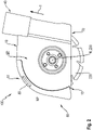
- a dust hood 100 according to the invention is in 1 shown.
- the dust hood 100 is equipped with a flange for attaching the dust hood 100 to a gear neck of an angle grinder (cf. 4 ).
- the dust hood has a hood body 10 for at least partially covering a circular cutting disk on both sides (cf. 3 , cutting disc 220).
- the dust hood 100 has a suction connection 40 via which the subsoil, for example in the form of dust, can be sucked off from the hood body 10 .
- the dust hood 100 is equipped with a depth stop 80 which is mounted on the hood body 10 via a single-arm bearing 81 on the flange side, ie on a flange side FS. Again 1 can be removed, the storage takes place via a bearing ring 83 which encloses the flange 90 annularly.
- the bearing ring 83 is part of the single-arm bearing 81 of the depth stop 80.
- the connecting flange 90 is formed onto the hood body.
- a drive spindle 230 of the angle grinder 200 protrudes coaxially through the flange 90 when the dust hood 100 is connected to the angle grinder 200 and the cutting disc 220 is accommodated in the dust hood 100 .
- the depth stop 80 is integrally formed with the single-arm bearing 81 and the bearing ring 83 from plastic.
- the depth stop 80 is mounted on its one-arm bearing 81 and in particular the bearing ring 83 exclusively on the flange side FS.
- the clamping nut side SP is free of any storage, in particular a centric storage by means of a bearing ring.
- the depth stop 80 is designed as a hood in the shape of a sector of a circle, which is guided on an end face 15 of the hood body and partially encompasses the end face 15 of the hood body 10 .
- this encompassing of the periphery of the hood body 10 should in particular not be understood as a bearing, but rather as a guiding aid.
- the in 1 shown dust hood 100 also free of a linear guide.
- the suction connection 40 which opens into a main suction channel 50 connected to it, is clearly visible.
- the main suction channel extends in the tangential direction T to the cutting disk 220 (cf. also 2 and 3 ).
- the main suction channel 50 is divided by a hood web 20 into two suction chambers 30, 30', which are designed symmetrically to one another and which improve the flow situation in the dust hood 100 in the course of a suction process.
- FIG 2 shows the dust hood 100 of FIG 1 looking at the clamping nut side SP.
- a circular cutting disk 220 in the form of a diamond disk. This is set in motion via the drive spindle 230 in the separating mode.
- the circular cutting disc 220 is partially covered by the hood body 10 on both sides. An uncovered part of the separating disk 220 projects out of the hood body 10 through a disk exit opening 70 on the underside of the hood body 10 .
- the clamping nut side SP is free of any bearings, or free of the reference to 1 described bearing ring 83. It is easy to see that the depth stop 80 partially encompasses an end face 15 of the hood body 10 and is thereby guided as an aid.
- FIG. 2 shows the zero position NP of the depth stop 80, ie the cutting disk 220 can dip into the ground to the maximum. A full cut is thus possible, in which a substrate, not shown here, preferably makes complete contact with the disc outlet opening 70 .
- the depth stop 80 has a position lock 87 which, in the exemplary embodiment shown here, has a spring element 89 integrated into the depth stop 80 .
- a position lock 87 which, in the exemplary embodiment shown here, has a spring element 89 integrated into the depth stop 80 .
- stepless rotation of the depth stop 80 about the axis of rotation R of the cutting disk 220 is possible via this spring element 89 .
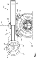
- 3 serves to illustrate a deployment position AP of the depth stop 80. This is initially based on FIG 2 the depth stop 80 is shown in the zero position NP. In addition to this, a depth stop 80′ which is in the deployed position AP is shown. In this context it should be mentioned that the representation of 3 is to be understood only schematically. In fact, the in 3 shown exhibition position AP and the zero position NP are not taken simultaneously.
- the depth stop 80 In its deployed position AP, the depth stop 80 protrudes beyond the pane exit opening in the direction of the substrate UG. Thus, a depth of cut not shown here cutting disc can be limited.
- the depth stop 80 is held in its deployed position AP by the spring element 89' that is also displaced.
- FIG 4 shows the dust hood together with a cut-off grinder 200 (cut-off grinder only partially shown).
- the dust hood 100 is connected to a gear neck 210 of the angle grinder 200 via the flange 90 (not shown here).
- the bearing ring 83 enclosing the flange (not shown here) is located between the angle grinder 200 and the hood body 10 .
- the clamping nut side SP is free of storage.
- FIG. 5 finally shows the depth stop 80 of the dust hood of FIG Figures 1 to 4 .
- the depth stop 80 der figure 5 is designed as a hood in the shape of a sector of a circle and implements a single-arm bearing 81 via which the depth stop 80 (as, for example, in 1 shown) can be connected to the hood body 10.
- the depth stop 80 with one-arm bearing 81, bearing ring 83 and position lock 87 together with the integrated spring element 89 is made in one piece from plastic. This results in a particularly favorable manufacturing option.
- the in figure 5 Depth stop 80 shown can be produced by a one-step injection molding process.
- the sector area SB running between the bearing ring 83 and a front area ST defines an "arm" of the single-arm bearing 81.
Landscapes
- Engineering & Computer Science (AREA)
- Mechanical Engineering (AREA)
- Life Sciences & Earth Sciences (AREA)
- Wood Science & Technology (AREA)
- Forests & Forestry (AREA)
- Grinding-Machine Dressing And Accessory Apparatuses (AREA)
- Finish Polishing, Edge Sharpening, And Grinding By Specific Grinding Devices (AREA)
- Sawing (AREA)
Description
- Die vorliegende Erfindung betrifft eine Staubhaube mit einem Flansch zum Befestigen der Staubhaube an einem Getriebehals eines Trennschleifers. Die Staubhaube ist ausgestattet mit einem Haubenkörper zum zumindest abschnittsweisen, beidseitigen Abdecken einer kreisförmigen Trennscheibe und mit einem Absauganschluss über den ein Untergrundabtrag aus dem Haubenkörper abgesaugt werden kann. Die Staubhaube weist einen Tiefenanschlag auf, mittels dem eine Schnitttiefe der Trennscheibe begrenzt werden kann.
- Staubhauben der eingangs genannten Art sind grundsätzlich aus dem Stand der Technik bekannt. Sie dienen der Vermeidung einer Staubausbreitung bei Trennarbeiten, um die Gesundheit eines Benutzers des Trennschleifers zu schützen.
- Die
KR 2015 0099624 A JP 2016 049574 A - Es ist Aufgabe der vorliegenden Erfindung, eine besonders einfach handhabbare Staubhaube bereitzustellen.
- Die Aufgabe wird durch eine Staubhaube gemäß Anspruch 1 gelöst.
- Bevorzugte Ausführungsformen sind in den abhängigen Ansprüchen offenbart.
- Die Erfindung schließt die Erkenntnis ein, dass Tiefenanschläge bei Staubhauben des Standes der Technik beidseitig des Haubenkörpers gelagert sind, was zum einen die Komplexität, zum anderen den Kraftbedarf bei der Tiefenverstellung (bewirkt durch Reibung) und den Bauraumbedarf erhöht. Dadurch ist die erfindungsgemäße Staubhaube besonders einfach handhabbar.
- In vorteilhafter Weiterbildung des Standes der Technik, ist der Tiefenanschlag der Staubhaube über eine Einarmlagerung flanschseitig, insbesondere ausschließlich flanschseitig am Haubenkörper gelagert. Dadurch ergibt sich zum einen ein vergleichsweise geringer Bauraumbedarf. Darüber hinaus ist eine einfachere konstruktive Gestaltung des Tiefenanschlags möglich, was sich beispielsweise in geringeren Kosten niederschlagen kann. Es hat sich als vorteilhaft herausgestellt, wenn die Einarmlagerung einen Lagerring aufweist, der den Flansch ringförmig umschließt. Derart kann ein Lagerdurchmesser der Einarmlagerung vergleichsweise klein gehalten werden, um Reibungskräfte gering zu halten.
- Eine vergleichsweise geringe Bauhöhe der Staubhaube kann insbesondere dadurch erreicht werden, dass die Spannmutterseite, das heißt die der Flanschseite gegenüberliegende Seite des Haubenkörpers, frei von einer Lagerung ist. Vorzugsweise ist diese Spannmutterseite frei von einem Lagerring.
- Es hat sich als vorteilhaft herausgestellt, wenn der Anschlussflansch an den Haubenkörper angeformt ist. Eine Antriebsspindel des Trennschleifers kann, wenn die Staubhaube mit dem Trennschleifer verbunden und die Trennscheibe in der Staubhaube aufgenommen ist, koaxial durch den Flansch hindurch ragen.
- Es hat sich als vorteilhaft herausgestellt, wenn der Tiefenanschlag mit der Einarmlagerung und dem Lagerring einstückig ausgebildet ist. Der Tiefenanschlag kann als kreissektorförmige Haube ausgebildet sein. Alternativ oder zusätzlich kann der Tiefenanschlag an einer Stirnseite des Haubenkörpers geführt sein und/oder kann der Tiefenanschlag eine Stirnseite des Haubenkörpers zumindest abschnittsweise umgreifen. Es hat sich als besonders vorteilhaft herausgestellt, wenn der Tiefenanschlag aus Kunststoff besteht.
- In einer weiteren bevorzugten Ausgestaltung weist der Tiefenanschlag eine Lagearretierung auf. Somit kann der Tiefenanschlag, in eine jeweiligen Relativlage bezüglich der Staubhaube, arretiert werden. Die Lagearretierung kann ein in den Tiefenanschlag integriertes Federelement aufweisen. Über dieses Federelement kann ein Schnapp- und/oder Rastmechanismus realisiert sein, über den eine Stufenverstellung der Trennscheibe, beispielsweise in 5-mm-Schritten erfolgen kann. Alternativ ist eine stufenlose Schnitttiefenverstellung der Trennscheibe mittels der Lagearretierung denkbar. Vorzugsweise ist das Federelement in einem aus Kunststoff bestehenden Tiefenanschlag funktionsintegriert. Das Federelement kann, im nicht ausgelenkten Zustand, Teil einer Oberfläche des Tiefenanschlags sein.
- Es hat sich als vorteilhaft herausgestellt, wenn der Tiefenanschlag ausschließlich durch Verdrehen um die Rotationsachse der Trennscheibe höhenverstellbar ist. Vorzugsweise ist der Tiefenanschlag frei von einer Linearführung.
- Erfindungsgemäß ist im Haubenkörper ein mit dem Absauganschluss verbundener Hauptabsaugkanal ausgebildet, der sich vorzugsweise tangential zur Trennscheibe erstreckt. Der Hauptabsaugkanal ist erfindungsgemäß durch einen Haubensteg in zwei Saugkammern unterteilt, die vorzugsweise symmetrisch zueinander ausgebildet sind.
- Die Aufgabe wird ebenfalls gelöst durch einen Trennschleifer mit einem Getriebehals, insbesondere einem Winkelschleifer, und mit einer Staubhaube der vorbeschriebenen Art, wobei die Staubhaube mittels ihres Flansches am Getriebehals angeordnet, bzw. anzuordnen ist. Dadurch, dass der Tiefenanschlag über eine Einarmlagerung flanschseitig am Haubenkörper gelagert ist, ist eine Lagerung des Tiefenanschlags zwischen Trennschleifer und Haubenkörper realisiert.
- Weitere Vorteile ergeben sich aus der folgenden Figurenbeschreibung. In den Figuren sind verschiedene Ausführungsbeispiele der vorliegenden Erfindung dargestellt. Die Figuren, die Beschreibung und die Ansprüche enthalten zahlreiche Merkmale in Kombination. Der Fachmann wird die Merkmale zweckmässigerweise auch einzeln betrachten und zu sinnvollen weiteren Kombinationen zusammenfassen.
- In den Figuren sind gleiche und gleichartige Komponenten mit gleichen Bezugszeichen beziffert.
- Es zeigen:
- Fig. 1
- ein bevorzugtes Ausführungsbeispiel einer erfindungsgemäßen Staubhaube in Draufsicht;
- Fig. 2
- eine spannmutterseitige Ansicht der Staubhaube aus
Fig. 1 mit ausgestelltem Tiefenanschlag; - Fig. 3
- die Staubhaube der
Fig. 1 und2 mit aufgenommener Trennscheibe; - Fig. 4
- die Staubhaube der
Figuren 1 bis 3 angeordnet an einem Trennschleifer; - Fig. 5
- den Tiefenanschlag der Staubhaube der
Figuren 1 bis 4 ; - Fig. 6
- eine Seitenansicht der Staubhaube der
Figuren 1 bis 4 aus Sicht des Trennschleifers. - Eine erfindungsgemäße Staubhaube 100 ist in
Fig. 1 dargestellt. Die Staubhaube 100 ist ausgestattet mit einem Flansch zum Befestigen der Staubhaube 100 an einem Getriebehals eines Trennschleifers (vgl.Fig. 4 ). Die Staubhaube weist einen Haubenkörper 10 zum zumindest abschnittsweisen, beidseitigen Abdecken einer kreisförmigen Trennscheibe (vgl.Fig. 3 , Trennscheibe 220) auf. Ferner verfügt die Staubhaube 100 über einen Absauganschluss 40 über den Untergrundabtrag, beispielsweise in Form von Staub, aus dem Haubenkörper 10 abgesaugt werden kann. - Erfindungsgemäß ist die Staubhaube 100 ausgestattet mit einem Tiefenanschlag 80, der über eine Einarmlagerung 81 flanschseitig, das heißt auf einer Flanschseite FS, am Haubenkörper 10 gelagert ist. Wie der
Fig. 1 entnommen werden kann, erfolgt die Lagerung über einen Lagerring 83, der den Flansch 90 ringförmig umschließt. Der Lagerring 83 ist Teil der Einarmlagerung 81 des Tiefenanschlags 80. - Der Anschlussflansch 90 ist an den Haubenkörper angeformt. Eine Antriebsspindel 230 des Trennschleifers 200 (vgl.
Fig. 4 ) ragt, wenn die Staubhaube 100 mit dem Trennschleifer 200 verbunden und die Trennscheibe 220 in der Staubhaube 100 aufgenommen ist, koaxial durch den Flansch 90 hindurch. - Wie bereits der
Fig. 1 entnommen werden kann, und mit Bezug auf die weiteren Figuren noch erläutert wird, ist der Tiefenanschlag 80 mit der Einarmlagerung 81 und dem Lagerring 83 einstückig aus Kunststoff ausgebildet. - Wie aus der in
Fig. 1 gezeigten Draufsicht besonders gut zu erkennen ist, ist der Tiefenanschlag 80 über seine Einarmlagerung 81 und insbesondere den Lagerring 83 ausschließlich auf der Flanschseite FS gelagert. Die Spannmutterseite SP ist frei von einer Lagerung, insbesondere einer zentrischen Lagerung mittels eines Lagerrings. - Wie insbesondere aus der Zusammenschau mit
Fig. 2 ersichtlich wird, ist der Tiefenanschlag 80 als kreissektorförmige Haube ausgebildet, die an einer Stimseite 15 des Haubenkörpers geführt ist und die Stirnseite 15 des Haubenkörpers 10 abschnittsweise umgreift. Dieser Umgriff in der Peripherie des Haubenkörpers 10 soll im Rahmen der vorliegenden Erfindung insbesondere nicht als Lagerung, sondern vielmehr als Führungshilfe verstanden werden. Somit ist die inFig. 1 gezeigte Staubhaube 100 auch frei von einer Linearführung. - Eine in der
Fig.1 nicht erkennbare kreisförmige Trennscheibe wird im Trennbetrieb um die Rotationsachse R in Drehrichtung DR angetrieben. - Auf der rechten Seite der
Fig. 1 gut zu erkennen ist der Absauganschluss 40, der in einen mit ihm verbundenen Hauptabsaugkanal 50 mündet. Der Hauptabsaugkanal erstreckt sich in tangentialer Richtung T zur Trennscheibe 220 (vgl. auchFig. 2 und3 ). Der Hauptabsaugkanal 50 ist durch einen Haubensteg 20 in zwei Saugkammern 30, 30' unterteilt, die symmetrisch zueinander ausgebildet sind und die die Strömungssituation in der Staubhaube 100 im Zuge eines Absaugvorgangs verbessern. -
Fig. 2 zeigt die Staubhaube 100 derFig. 1 mit Blick auf die Spannmutterseite SP. In der Staubhaube 100 aufgenommen ist eine kreisförmige Trennscheibe 220 in Form einer Diamantscheibe. Diese wird im Trennbetrieb über die Antriebsspindel 230 in Bewegung gesetzt. Die kreisförmige Trennscheibe 220 ist durch den Haubenkörper 10 beidseitig abschnittsweise abgedeckt. Ein nicht abgedeckter Teil der Trennscheibe 220 ragt durch eine Scheibenaustrittsöffnung 70 auf der Unterseite des Haubenkörpers 10 aus dem Haubenkörper 10 hinaus. - Wie der
Fig. 2 entnommen werden kann, ist die Spannmutterseite SP frei von etwaigen Lagerungen, bzw. frei von dem mit Bezug aufFig. 1 beschriebenen Lagerring 83. Gut zu erkennen ist, dass der Tiefenanschlag 80 eine Stirnseite 15 des Haubenkörpers 10 abschnittsweise umgreift und dadurch hilfsweise geführt ist. -
Fig. 2 zeigt die Nullposition NP des Tiefenanschlags 80, das heißt die Trennscheibe 220 kann maximal in den Untergrund eintauchen. Somit ist ein Vollschnitt möglich, bei dem ein hier nicht gezeigter Untergrund die Scheibenaustrittsöffnung 70 vorzugsweise vollständig kontaktiert. - Im oberen Bereich weist der Tiefenanschlag 80 eine Lagearretierung 87 auf, die im vorliegend dargestellten Ausführungsbeispiel ein in den Tiefenanschlag 80 integriertes Federelement 89 aufweist. Über dieses Federelement 89 ist im vorliegenden Fall ein stufenloses Verdrehen des Tiefenanschlags 80 um die Rotationsachse R der Trennscheibe 220 möglich.
-
Fig. 3 dient der Verdeutlichung einer Ausstellposition AP des Tiefenanschlags 80. Dazu ist zunächst in Anlehnung anFig. 2 der Tiefenanschlag 80 in Nullposition NP dargestellt. Zusätzlich dazu ist ein in Ausstellposition AP ausgestellter Tiefenanschlag 80' gezeigt. In diesem Zusammenhang sei erwähnt, dass die Darstellung derFig. 3 ausschließlich schematisch zu verstehen ist. Tatsächlich können die inFig. 3 gezeigte Ausstellposition AP und die Nullposition NP nicht gleichzeitig eingenommen werden. - In seiner Ausstellposition AP ragt der Tiefenanschlag 80 über die Scheibenaustrittsöffnung hinaus in Richtung des Untergrunds UG. Somit kann eine Schnitttiefe der hier nicht gezeigten Trennscheibe begrenzt werden. Durch das mitverschobenen Federelement 89' wird der Tiefenanschlag 80 in seiner Ausstellposition AP gehalten.
-
Fig. 4 zeigt die Staubhaube zusammen mit einem Trennschleifer 200 (Trennschleifer nur teilweise dargestellt). Über den hier nicht gezeigten Flansch 90 ist die Staubhaube 100 an einem Getriebehals 210 des Trennschleifers 200 angeschlossen. Der den hier nicht dargestellten Flansch umschließende Lagerring 83 ist zwischen Trennschleifer 200 und Haubenkörper 10 befindlich. Die Spannmutterseite SP ist frei von einer Lagerung. -
Fig. 5 zeigt schließlich den Tiefenanschlag 80 der Staubhaube derFiguren 1 bis 4 . Der Tiefenanschlag 80 derFig. 5 ist als kreissektorförmige Haube ausgebildet und realisiert eine Einarmlagerung 81 über die der Tiefenanschlag 80 (wie beispielsweise inFig. 1 gezeigt) am Haubenkörper 10 angeschlossen werden kann. - Wie der
Fig. 5 entnommen werden kann, ist der Tiefenanschlag 80 mit Einarmlagerung 81, Lagerring 83 sowie Lagearretierung 87 nebst integriertem Federelement 89 einstückig aus Kunststoff ausgebildet. Somit ergibt sich eine besonders günstige Fertigungsmöglichkeit. Beispielsweise kann der inFig. 5 gezeigte Tiefenanschlag 80 durch einen einschrittigen Spritzgussvorgang hergestellt werden. Der zwischen Lagerring 83 und einem Stirnbereich ST verlaufende Sektorbereich SB definiert einen "Arm" der Einarmlagerung 81. -
Fig. 6 zeigt schließlich die Staubhaube 100, angeschlossen an einem Trennschleifer 200, aus Sicht des Trennschleifers 200. Die im Haubenkörper 10 abschnittsweise, beidseitig aufgenommene kreisförmige Trennscheibe 220 dreht sich im Trennbetrieb in Drehrichtung DR, im Falle derFig. 6 bedeutet dies eine Drehrichtung DR im Uhrzeigersinn. -
- 10
- Haubenkörper
- 20
- Haubensteg
- 30, 30'
- Saugkammern
- 50
- Hauptabsaugkanal
- 70
- Scheibenaustrittsöffnung
- 80
- Tiefenanschlag
- 81
- Einarmlagerung
- 83
- Lagerring
- 87
- Lagearretierung
- 89
- Federelement
- 90
- Flansch
- 100
- Staubhaube
- 200
- Trennschleifer
- 210
- Getriebehals
- 220
- Schleifscheibe
- 230
- Antriebsspindel
- AP
- Ausstellposition des Tiefenanschlags
- DR
- Drehrichtung der Schleifscheibe
- FS
- Flanschseite
- R
- Rotationsachse der Schleifscheibe
- NP
- Nullposition des Tiefenanschlags
- SP
- Spannmutterseite
- SB
- Sektorbereich
- ST
- Stirnbereich
- T
- Tangentialrichtung
- UG
- Untergrund
Claims (13)
- Staubhaube (100) mit einem Flansch (90) zum Befestigen der Staubhaube (100) an einem Getriebehals (210) eines Trennschleifers (200), und mit einem Haubenkörper (10) zum zumindest abschnittsweisen, beidseitigen Abdecken einer kreisförmigen Trennscheibe (220), und mit einem Absauganschluss (40) über den ein Untergrundabtrag aus dem Haubenkörper (10) abgesaugt werden kann, wobei die Staubhaube (100) einen Tiefenanschlag (80) aufweist mittels dem eine Schnitttiefe der Trennscheibe (220) begrenzt werden kann,
dadurch gekennzeichnet, dassder Tiefenanschlag (80) über eine Einarmlagerung (81) flanschseitig am Haubenkörper (10) gelagert ist undwobei der Haubenkörper (10) einen Hauptabsaugkanal (50) umfasst, wobei der Hauptabsaugkanal (50) durch einen Haubensteg (20) in zwei Saugkammern (30, 30') unterteilt wird. - Staubhaube (100) nach einem der vorangehenden Ansprüche,
dadurch gekennzeichnet, dass die Einarmlagerung (81) einen Lagerring (83) aufweist, der den Flansch (90) ringförmig umschließt. - Staubhaube (100) nach einem der vorangehenden Ansprüche,
dadurch gekennzeichnet, dass der Anschlussflansch (90) an den Haubenkörper (10) angeformt ist. - Staubhaube (100) nach einem der vorangehenden Ansprüche,
dadurch gekennzeichnet, dass der Tiefenanschlag (80) mit der Einarmlagerung (81) und dem Lagerring (83) einstückig ausgebildet ist. - Staubhaube (100) nach einem der vorangehenden Ansprüche,
dadurch gekennzeichnet, dass der Tiefenanschlag (80) als kreissektorförmige Haube ausgebildet ist. - Staubhaube (100) nach einem der vorangehenden Ansprüche,
dadurch gekennzeichnet, dass der Tiefenanschlag (80) an einer Stirnseite (15) des Haubenkörpers (10) geführt ist und/oder der Tiefenanschlag (80) eine Stirnseite (15) des Haubenkörpers (10) zumindest abschnittsweise umgreift. - Staubhaube (100) nach einem der vorangehenden Ansprüche,
dadurch gekennzeichnet, dass der Tiefenanschlag (80) aus Kunststoff besteht. - Staubhaube (100) nach einem der vorangehenden Ansprüche,
dadurch gekennzeichnet, dass der Tiefenanschlag (80) eine Lagearretierung (87) aufweist, die insbesondere ein in den Tiefenanschlag (80) integriertes Federelement (89) aufweist. - Staubhaube (100) nach einem der vorangehenden Ansprüche,
dadurch gekennzeichnet, dass der Tiefenanschlag (80) ausschließlich durch Verdrehen um die Rotationsachse (R) der Trennscheibe (220) höhenverstellbar ist. - Staubhaube (100) nach einem der vorangehenden Ansprüche,
dadurch gekennzeichnet, dass der Tiefenanschlag (80) frei von einer Linearführung ist. - Staubhaube (100) nach einem der vorangehenden Ansprüche,
dadurch gekennzeichnet, dass im Haubenkörper (10) ein mit dem Absauganschluss (40) verbundener Hauptabsaugkanal (50) ausgebildet ist, der sich tangential zur Trennscheibe (220) erstreckt. - Staubhaube (100) nach einem der vorangehenden Ansprüche,
dadurch gekennzeichnet, dass die zwei Saugkammern (30, 30') symmetrisch zueinander ausgebildet sind. - Trennschleifer (200) mit einem Getriebehals (210) und mit einer Staubhaube (100) nach einen der vorangehenden Ansprüche, wobei die Staubhaube (100) mittels ihres Flansches (90) am Getriebehals (210) angeordnet bzw. anzuordnen ist.
Applications Claiming Priority (2)
| Application Number | Priority Date | Filing Date | Title |
|---|---|---|---|
| EP16202353.5A EP3332908A1 (de) | 2016-12-06 | 2016-12-06 | Staubhaube für einen trennschleifer |
| PCT/EP2017/079433 WO2018104018A1 (de) | 2016-12-06 | 2017-11-16 | Staubhaube für einen trennschleifer |
Publications (2)
| Publication Number | Publication Date |
|---|---|
| EP3551379A1 EP3551379A1 (de) | 2019-10-16 |
| EP3551379B1 true EP3551379B1 (de) | 2023-01-04 |
Family
ID=57544225
Family Applications (2)
| Application Number | Title | Priority Date | Filing Date |
|---|---|---|---|
| EP16202353.5A Withdrawn EP3332908A1 (de) | 2016-12-06 | 2016-12-06 | Staubhaube für einen trennschleifer |
| EP17809211.0A Active EP3551379B1 (de) | 2016-12-06 | 2017-11-16 | Staubhaube für einen trennschleifer |
Family Applications Before (1)
| Application Number | Title | Priority Date | Filing Date |
|---|---|---|---|
| EP16202353.5A Withdrawn EP3332908A1 (de) | 2016-12-06 | 2016-12-06 | Staubhaube für einen trennschleifer |
Country Status (2)
| Country | Link |
|---|---|
| EP (2) | EP3332908A1 (de) |
| WO (1) | WO2018104018A1 (de) |
Families Citing this family (1)
| Publication number | Priority date | Publication date | Assignee | Title |
|---|---|---|---|---|
| CN112605764A (zh) * | 2021-01-11 | 2021-04-06 | 石家庄泽裕科技有限公司 | 一种装修用大理石板定厚打磨装置 |
Family Cites Families (3)
| Publication number | Priority date | Publication date | Assignee | Title |
|---|---|---|---|---|
| US6048260A (en) * | 1999-07-01 | 2000-04-11 | Roto-Zip Tool Corporation | Angle attachment for power tool |
| KR101635073B1 (ko) * | 2014-02-21 | 2016-07-04 | 삼성중공업 주식회사 | 절삭 깊이를 조절할 수 있는 절삭 장치 |
| JP6316709B2 (ja) * | 2014-08-28 | 2018-04-25 | 株式会社マキタ | 先端工具カバー及び電動工具 |
-
2016
- 2016-12-06 EP EP16202353.5A patent/EP3332908A1/de not_active Withdrawn
-
2017
- 2017-11-16 WO PCT/EP2017/079433 patent/WO2018104018A1/de not_active Ceased
- 2017-11-16 EP EP17809211.0A patent/EP3551379B1/de active Active
Also Published As
| Publication number | Publication date |
|---|---|
| WO2018104018A1 (de) | 2018-06-14 |
| EP3332908A1 (de) | 2018-06-13 |
| EP3551379A1 (de) | 2019-10-16 |
Similar Documents
| Publication | Publication Date | Title |
|---|---|---|
| EP1819481B1 (de) | Vorrichtung zum trennen und schleifen, spannvorrichtung und rotierendes werkzeug mit vibrationsdämpfung | |
| EP3380271B1 (de) | Tragbare, handgeführte trennschleifmaschine | |
| EP2593233B1 (de) | Messerträger für zerkleinerungsvorrichtungen | |
| DE102007052685A1 (de) | Handwerkzeugmaschine | |
| EP3173188A1 (de) | Tragbare, handgeführte trennschleifmaschine | |
| DE8629226U1 (de) | Drehwerkzeug zur Randbearbeitung von Brillenglasrändern | |
| EP3551379B1 (de) | Staubhaube für einen trennschleifer | |
| DE69405935T2 (de) | Vorrichtung zum manuellen Anbringen und Abmontieren von Bearbeitungsscheiben auf Handwerkzeugmaschinen für Oberflächenbearbeitung | |
| EP1133910A1 (de) | Lagerschild eines Mähtellers | |
| DE102013105616A1 (de) | Werkzeug zum Bearbeiten von Materialien | |
| DE102007008353B4 (de) | Rohrtrennvorrichtung | |
| DE102013005000B4 (de) | Gerätekopf für ein Werkzeuggerät, insbesondere für eine Ringkreissäge oder einen Winkelschleifer | |
| EP2877070B1 (de) | Scheibenraffel | |
| DE102017223793A1 (de) | Schneidscheibe | |
| EP3519140B1 (de) | Staubhaube für ein schleifgerät | |
| EP3551382B1 (de) | Staubhaube für ein schleifgerät | |
| DE10034466A1 (de) | Handwerkzeugmaschine | |
| DE202004018583U1 (de) | Vorrichtung zum Trennen und Schleifen mit Vibrationsdämpfung und dafür geeignetes Werkzeug | |
| DE202019105846U1 (de) | Elektrohandwerkzeugmaschine | |
| DE202005010515U1 (de) | Vorrichtung zur abtragenden Behandlung von Hornhaut | |
| DE8816301U1 (de) | Kettensäge | |
| DE60122979T2 (de) | Scheibe zum Anfasen von Rohrenden | |
| EP3934847B1 (de) | System umfassend eine staubhaubenerweiterungsvorrichtung und einen adapter | |
| EP3634195B1 (de) | Saugdüse für eine handfräse | |
| DE102010015961A1 (de) | Rotierend antreibbares Werkzeug zur Bearbeitung der Stirnflächen von Glasplatten |
Legal Events
| Date | Code | Title | Description |
|---|---|---|---|
| STAA | Information on the status of an ep patent application or granted ep patent |
Free format text: STATUS: UNKNOWN |
|
| STAA | Information on the status of an ep patent application or granted ep patent |
Free format text: STATUS: THE INTERNATIONAL PUBLICATION HAS BEEN MADE |
|
| PUAI | Public reference made under article 153(3) epc to a published international application that has entered the european phase |
Free format text: ORIGINAL CODE: 0009012 |
|
| STAA | Information on the status of an ep patent application or granted ep patent |
Free format text: STATUS: REQUEST FOR EXAMINATION WAS MADE |
|
| 17P | Request for examination filed |
Effective date: 20190708 |
|
| AK | Designated contracting states |
Kind code of ref document: A1 Designated state(s): AL AT BE BG CH CY CZ DE DK EE ES FI FR GB GR HR HU IE IS IT LI LT LU LV MC MK MT NL NO PL PT RO RS SE SI SK SM TR |
|
| AX | Request for extension of the european patent |
Extension state: BA ME |
|
| DAV | Request for validation of the european patent (deleted) | ||
| DAX | Request for extension of the european patent (deleted) | ||
| GRAP | Despatch of communication of intention to grant a patent |
Free format text: ORIGINAL CODE: EPIDOSNIGR1 |
|
| STAA | Information on the status of an ep patent application or granted ep patent |
Free format text: STATUS: GRANT OF PATENT IS INTENDED |
|
| INTG | Intention to grant announced |
Effective date: 20220921 |
|
| GRAS | Grant fee paid |
Free format text: ORIGINAL CODE: EPIDOSNIGR3 |
|
| GRAA | (expected) grant |
Free format text: ORIGINAL CODE: 0009210 |
|
| STAA | Information on the status of an ep patent application or granted ep patent |
Free format text: STATUS: THE PATENT HAS BEEN GRANTED |
|
| AK | Designated contracting states |
Kind code of ref document: B1 Designated state(s): AL AT BE BG CH CY CZ DE DK EE ES FI FR GB GR HR HU IE IS IT LI LT LU LV MC MK MT NL NO PL PT RO RS SE SI SK SM TR |
|
| REG | Reference to a national code |
Ref country code: GB Ref legal event code: FG4D Free format text: NOT ENGLISH |
|
| REG | Reference to a national code |
Ref country code: DE Ref legal event code: R096 Ref document number: 502017014302 Country of ref document: DE |
|
| REG | Reference to a national code |
Ref country code: CH Ref legal event code: EP |
|
| REG | Reference to a national code |
Ref country code: AT Ref legal event code: REF Ref document number: 1541591 Country of ref document: AT Kind code of ref document: T Effective date: 20230115 |
|
| REG | Reference to a national code |
Ref country code: IE Ref legal event code: FG4D Free format text: LANGUAGE OF EP DOCUMENT: GERMAN |
|
| REG | Reference to a national code |
Ref country code: SE Ref legal event code: TRGR |
|
| REG | Reference to a national code |
Ref country code: LT Ref legal event code: MG9D |
|
| REG | Reference to a national code |
Ref country code: NL Ref legal event code: MP Effective date: 20230104 |
|
| PG25 | Lapsed in a contracting state [announced via postgrant information from national office to epo] |
Ref country code: NL Free format text: LAPSE BECAUSE OF FAILURE TO SUBMIT A TRANSLATION OF THE DESCRIPTION OR TO PAY THE FEE WITHIN THE PRESCRIBED TIME-LIMIT Effective date: 20230104 |
|
| PG25 | Lapsed in a contracting state [announced via postgrant information from national office to epo] |
Ref country code: RS Free format text: LAPSE BECAUSE OF FAILURE TO SUBMIT A TRANSLATION OF THE DESCRIPTION OR TO PAY THE FEE WITHIN THE PRESCRIBED TIME-LIMIT Effective date: 20230104 Ref country code: PT Free format text: LAPSE BECAUSE OF FAILURE TO SUBMIT A TRANSLATION OF THE DESCRIPTION OR TO PAY THE FEE WITHIN THE PRESCRIBED TIME-LIMIT Effective date: 20230504 Ref country code: NO Free format text: LAPSE BECAUSE OF FAILURE TO SUBMIT A TRANSLATION OF THE DESCRIPTION OR TO PAY THE FEE WITHIN THE PRESCRIBED TIME-LIMIT Effective date: 20230404 Ref country code: LV Free format text: LAPSE BECAUSE OF FAILURE TO SUBMIT A TRANSLATION OF THE DESCRIPTION OR TO PAY THE FEE WITHIN THE PRESCRIBED TIME-LIMIT Effective date: 20230104 Ref country code: LT Free format text: LAPSE BECAUSE OF FAILURE TO SUBMIT A TRANSLATION OF THE DESCRIPTION OR TO PAY THE FEE WITHIN THE PRESCRIBED TIME-LIMIT Effective date: 20230104 Ref country code: HR Free format text: LAPSE BECAUSE OF FAILURE TO SUBMIT A TRANSLATION OF THE DESCRIPTION OR TO PAY THE FEE WITHIN THE PRESCRIBED TIME-LIMIT Effective date: 20230104 Ref country code: ES Free format text: LAPSE BECAUSE OF FAILURE TO SUBMIT A TRANSLATION OF THE DESCRIPTION OR TO PAY THE FEE WITHIN THE PRESCRIBED TIME-LIMIT Effective date: 20230104 |
|
| PG25 | Lapsed in a contracting state [announced via postgrant information from national office to epo] |
Ref country code: PL Free format text: LAPSE BECAUSE OF FAILURE TO SUBMIT A TRANSLATION OF THE DESCRIPTION OR TO PAY THE FEE WITHIN THE PRESCRIBED TIME-LIMIT Effective date: 20230104 Ref country code: IS Free format text: LAPSE BECAUSE OF FAILURE TO SUBMIT A TRANSLATION OF THE DESCRIPTION OR TO PAY THE FEE WITHIN THE PRESCRIBED TIME-LIMIT Effective date: 20230504 Ref country code: GR Free format text: LAPSE BECAUSE OF FAILURE TO SUBMIT A TRANSLATION OF THE DESCRIPTION OR TO PAY THE FEE WITHIN THE PRESCRIBED TIME-LIMIT Effective date: 20230405 Ref country code: FI Free format text: LAPSE BECAUSE OF FAILURE TO SUBMIT A TRANSLATION OF THE DESCRIPTION OR TO PAY THE FEE WITHIN THE PRESCRIBED TIME-LIMIT Effective date: 20230104 |
|
| REG | Reference to a national code |
Ref country code: DE Ref legal event code: R097 Ref document number: 502017014302 Country of ref document: DE |
|
| PG25 | Lapsed in a contracting state [announced via postgrant information from national office to epo] |
Ref country code: SM Free format text: LAPSE BECAUSE OF FAILURE TO SUBMIT A TRANSLATION OF THE DESCRIPTION OR TO PAY THE FEE WITHIN THE PRESCRIBED TIME-LIMIT Effective date: 20230104 Ref country code: RO Free format text: LAPSE BECAUSE OF FAILURE TO SUBMIT A TRANSLATION OF THE DESCRIPTION OR TO PAY THE FEE WITHIN THE PRESCRIBED TIME-LIMIT Effective date: 20230104 Ref country code: EE Free format text: LAPSE BECAUSE OF FAILURE TO SUBMIT A TRANSLATION OF THE DESCRIPTION OR TO PAY THE FEE WITHIN THE PRESCRIBED TIME-LIMIT Effective date: 20230104 Ref country code: DK Free format text: LAPSE BECAUSE OF FAILURE TO SUBMIT A TRANSLATION OF THE DESCRIPTION OR TO PAY THE FEE WITHIN THE PRESCRIBED TIME-LIMIT Effective date: 20230104 Ref country code: CZ Free format text: LAPSE BECAUSE OF FAILURE TO SUBMIT A TRANSLATION OF THE DESCRIPTION OR TO PAY THE FEE WITHIN THE PRESCRIBED TIME-LIMIT Effective date: 20230104 |
|
| PLBE | No opposition filed within time limit |
Free format text: ORIGINAL CODE: 0009261 |
|
| STAA | Information on the status of an ep patent application or granted ep patent |
Free format text: STATUS: NO OPPOSITION FILED WITHIN TIME LIMIT |
|
| PG25 | Lapsed in a contracting state [announced via postgrant information from national office to epo] |
Ref country code: SK Free format text: LAPSE BECAUSE OF FAILURE TO SUBMIT A TRANSLATION OF THE DESCRIPTION OR TO PAY THE FEE WITHIN THE PRESCRIBED TIME-LIMIT Effective date: 20230104 |
|
| 26N | No opposition filed |
Effective date: 20231005 |
|
| PG25 | Lapsed in a contracting state [announced via postgrant information from national office to epo] |
Ref country code: SI Free format text: LAPSE BECAUSE OF FAILURE TO SUBMIT A TRANSLATION OF THE DESCRIPTION OR TO PAY THE FEE WITHIN THE PRESCRIBED TIME-LIMIT Effective date: 20230104 |
|
| PG25 | Lapsed in a contracting state [announced via postgrant information from national office to epo] |
Ref country code: IT Free format text: LAPSE BECAUSE OF FAILURE TO SUBMIT A TRANSLATION OF THE DESCRIPTION OR TO PAY THE FEE WITHIN THE PRESCRIBED TIME-LIMIT Effective date: 20230104 |
|
| REG | Reference to a national code |
Ref country code: CH Ref legal event code: PL |
|
| PG25 | Lapsed in a contracting state [announced via postgrant information from national office to epo] |
Ref country code: MC Free format text: LAPSE BECAUSE OF FAILURE TO SUBMIT A TRANSLATION OF THE DESCRIPTION OR TO PAY THE FEE WITHIN THE PRESCRIBED TIME-LIMIT Effective date: 20230104 |
|
| PG25 | Lapsed in a contracting state [announced via postgrant information from national office to epo] |
Ref country code: LU Free format text: LAPSE BECAUSE OF NON-PAYMENT OF DUE FEES Effective date: 20231116 |
|
| PG25 | Lapsed in a contracting state [announced via postgrant information from national office to epo] |
Ref country code: CH Free format text: LAPSE BECAUSE OF NON-PAYMENT OF DUE FEES Effective date: 20231130 |
|
| PG25 | Lapsed in a contracting state [announced via postgrant information from national office to epo] |
Ref country code: MC Free format text: LAPSE BECAUSE OF FAILURE TO SUBMIT A TRANSLATION OF THE DESCRIPTION OR TO PAY THE FEE WITHIN THE PRESCRIBED TIME-LIMIT Effective date: 20230104 Ref country code: LU Free format text: LAPSE BECAUSE OF NON-PAYMENT OF DUE FEES Effective date: 20231116 Ref country code: CH Free format text: LAPSE BECAUSE OF NON-PAYMENT OF DUE FEES Effective date: 20231130 |
|
| REG | Reference to a national code |
Ref country code: BE Ref legal event code: MM Effective date: 20231130 |
|
| REG | Reference to a national code |
Ref country code: IE Ref legal event code: MM4A |
|
| PG25 | Lapsed in a contracting state [announced via postgrant information from national office to epo] |
Ref country code: IE Free format text: LAPSE BECAUSE OF NON-PAYMENT OF DUE FEES Effective date: 20231116 |
|
| PG25 | Lapsed in a contracting state [announced via postgrant information from national office to epo] |
Ref country code: BE Free format text: LAPSE BECAUSE OF NON-PAYMENT OF DUE FEES Effective date: 20231130 |
|
| PG25 | Lapsed in a contracting state [announced via postgrant information from national office to epo] |
Ref country code: IE Free format text: LAPSE BECAUSE OF NON-PAYMENT OF DUE FEES Effective date: 20231116 Ref country code: BE Free format text: LAPSE BECAUSE OF NON-PAYMENT OF DUE FEES Effective date: 20231130 |
|
| PG25 | Lapsed in a contracting state [announced via postgrant information from national office to epo] |
Ref country code: BG Free format text: LAPSE BECAUSE OF FAILURE TO SUBMIT A TRANSLATION OF THE DESCRIPTION OR TO PAY THE FEE WITHIN THE PRESCRIBED TIME-LIMIT Effective date: 20230104 |
|
| PG25 | Lapsed in a contracting state [announced via postgrant information from national office to epo] |
Ref country code: BG Free format text: LAPSE BECAUSE OF FAILURE TO SUBMIT A TRANSLATION OF THE DESCRIPTION OR TO PAY THE FEE WITHIN THE PRESCRIBED TIME-LIMIT Effective date: 20230104 |
|
| REG | Reference to a national code |
Ref country code: AT Ref legal event code: MM01 Ref document number: 1541591 Country of ref document: AT Kind code of ref document: T Effective date: 20231116 |
|
| PG25 | Lapsed in a contracting state [announced via postgrant information from national office to epo] |
Ref country code: AT Free format text: LAPSE BECAUSE OF NON-PAYMENT OF DUE FEES Effective date: 20231116 |
|
| PG25 | Lapsed in a contracting state [announced via postgrant information from national office to epo] |
Ref country code: AT Free format text: LAPSE BECAUSE OF NON-PAYMENT OF DUE FEES Effective date: 20231116 |
|
| PG25 | Lapsed in a contracting state [announced via postgrant information from national office to epo] |
Ref country code: CY Free format text: LAPSE BECAUSE OF FAILURE TO SUBMIT A TRANSLATION OF THE DESCRIPTION OR TO PAY THE FEE WITHIN THE PRESCRIBED TIME-LIMIT; INVALID AB INITIO Effective date: 20171116 |
|
| PG25 | Lapsed in a contracting state [announced via postgrant information from national office to epo] |
Ref country code: HU Free format text: LAPSE BECAUSE OF FAILURE TO SUBMIT A TRANSLATION OF THE DESCRIPTION OR TO PAY THE FEE WITHIN THE PRESCRIBED TIME-LIMIT; INVALID AB INITIO Effective date: 20171116 |
|
| PG25 | Lapsed in a contracting state [announced via postgrant information from national office to epo] |
Ref country code: TR Free format text: LAPSE BECAUSE OF FAILURE TO SUBMIT A TRANSLATION OF THE DESCRIPTION OR TO PAY THE FEE WITHIN THE PRESCRIBED TIME-LIMIT Effective date: 20230104 |
|
| PGFP | Annual fee paid to national office [announced via postgrant information from national office to epo] |
Ref country code: DE Payment date: 20251119 Year of fee payment: 9 |
|
| PGFP | Annual fee paid to national office [announced via postgrant information from national office to epo] |
Ref country code: GB Payment date: 20251121 Year of fee payment: 9 |
|
| PGFP | Annual fee paid to national office [announced via postgrant information from national office to epo] |
Ref country code: FR Payment date: 20251126 Year of fee payment: 9 |
|
| PGFP | Annual fee paid to national office [announced via postgrant information from national office to epo] |
Ref country code: SE Payment date: 20251119 Year of fee payment: 9 |