EP3551372B1 - Appareil de traitement au laser, et procédé de découpe d'une pièce par un faisceau laser - Google Patents
Appareil de traitement au laser, et procédé de découpe d'une pièce par un faisceau laser Download PDFInfo
- Publication number
- EP3551372B1 EP3551372B1 EP16923523.1A EP16923523A EP3551372B1 EP 3551372 B1 EP3551372 B1 EP 3551372B1 EP 16923523 A EP16923523 A EP 16923523A EP 3551372 B1 EP3551372 B1 EP 3551372B1
- Authority
- EP
- European Patent Office
- Prior art keywords
- laser
- laser beam
- core
- workpiece
- output
- Prior art date
- Legal status (The legal status is an assumption and is not a legal conclusion. Google has not performed a legal analysis and makes no representation as to the accuracy of the status listed.)
- Active
Links
Images


Classifications
-
- B—PERFORMING OPERATIONS; TRANSPORTING
- B23—MACHINE TOOLS; METAL-WORKING NOT OTHERWISE PROVIDED FOR
- B23K—SOLDERING OR UNSOLDERING; WELDING; CLADDING OR PLATING BY SOLDERING OR WELDING; CUTTING BY APPLYING HEAT LOCALLY, e.g. FLAME CUTTING; WORKING BY LASER BEAM
- B23K26/00—Working by laser beam, e.g. welding, cutting or boring
- B23K26/02—Positioning or observing the workpiece, e.g. with respect to the point of impact; Aligning, aiming or focusing the laser beam
- B23K26/06—Shaping the laser beam, e.g. by masks or multi-focusing
- B23K26/0604—Shaping the laser beam, e.g. by masks or multi-focusing by a combination of beams
- B23K26/0608—Shaping the laser beam, e.g. by masks or multi-focusing by a combination of beams in the same heat affected zone [HAZ]
-
- B—PERFORMING OPERATIONS; TRANSPORTING
- B23—MACHINE TOOLS; METAL-WORKING NOT OTHERWISE PROVIDED FOR
- B23K—SOLDERING OR UNSOLDERING; WELDING; CLADDING OR PLATING BY SOLDERING OR WELDING; CUTTING BY APPLYING HEAT LOCALLY, e.g. FLAME CUTTING; WORKING BY LASER BEAM
- B23K26/00—Working by laser beam, e.g. welding, cutting or boring
- B23K26/02—Positioning or observing the workpiece, e.g. with respect to the point of impact; Aligning, aiming or focusing the laser beam
- B23K26/06—Shaping the laser beam, e.g. by masks or multi-focusing
- B23K26/073—Shaping the laser spot
-
- B—PERFORMING OPERATIONS; TRANSPORTING
- B23—MACHINE TOOLS; METAL-WORKING NOT OTHERWISE PROVIDED FOR
- B23K—SOLDERING OR UNSOLDERING; WELDING; CLADDING OR PLATING BY SOLDERING OR WELDING; CUTTING BY APPLYING HEAT LOCALLY, e.g. FLAME CUTTING; WORKING BY LASER BEAM
- B23K26/00—Working by laser beam, e.g. welding, cutting or boring
- B23K26/36—Removing material
- B23K26/38—Removing material by boring or cutting
-
- G—PHYSICS
- G02—OPTICS
- G02B—OPTICAL ELEMENTS, SYSTEMS OR APPARATUS
- G02B6/00—Light guides; Structural details of arrangements comprising light guides and other optical elements, e.g. couplings
- G02B6/02—Optical fibres with cladding with or without a coating
- G02B6/02042—Multicore optical fibres
-
- G—PHYSICS
- G02—OPTICS
- G02B—OPTICAL ELEMENTS, SYSTEMS OR APPARATUS
- G02B6/00—Light guides; Structural details of arrangements comprising light guides and other optical elements, e.g. couplings
- G02B6/02—Optical fibres with cladding with or without a coating
- G02B6/036—Optical fibres with cladding with or without a coating core or cladding comprising multiple layers
-
- G—PHYSICS
- G02—OPTICS
- G02B—OPTICAL ELEMENTS, SYSTEMS OR APPARATUS
- G02B6/00—Light guides; Structural details of arrangements comprising light guides and other optical elements, e.g. couplings
- G02B6/04—Light guides; Structural details of arrangements comprising light guides and other optical elements, e.g. couplings formed by bundles of fibres
-
- G—PHYSICS
- G02—OPTICS
- G02B—OPTICAL ELEMENTS, SYSTEMS OR APPARATUS
- G02B6/00—Light guides; Structural details of arrangements comprising light guides and other optical elements, e.g. couplings
- G02B6/02—Optical fibres with cladding with or without a coating
- G02B6/02295—Microstructured optical fibre
- G02B6/02314—Plurality of longitudinal structures extending along optical fibre axis, e.g. holes
- G02B6/02319—Plurality of longitudinal structures extending along optical fibre axis, e.g. holes characterised by core or core-cladding interface features
- G02B6/02338—Structured core, e.g. core contains more than one material, non-constant refractive index distribution in core, asymmetric or non-circular elements in core unit, multiple cores, insertions between core and clad
-
- G—PHYSICS
- G02—OPTICS
- G02B—OPTICAL ELEMENTS, SYSTEMS OR APPARATUS
- G02B6/00—Light guides; Structural details of arrangements comprising light guides and other optical elements, e.g. couplings
- G02B6/02—Optical fibres with cladding with or without a coating
- G02B6/036—Optical fibres with cladding with or without a coating core or cladding comprising multiple layers
- G02B6/03605—Highest refractive index not on central axis
- G02B6/03611—Highest index adjacent to central axis region, e.g. annular core, coaxial ring, centreline depression affecting waveguiding
-
- G—PHYSICS
- G02—OPTICS
- G02B—OPTICAL ELEMENTS, SYSTEMS OR APPARATUS
- G02B6/00—Light guides; Structural details of arrangements comprising light guides and other optical elements, e.g. couplings
- G02B6/02—Optical fibres with cladding with or without a coating
- G02B6/036—Optical fibres with cladding with or without a coating core or cladding comprising multiple layers
- G02B6/03616—Optical fibres characterised both by the number of different refractive index layers around the central core segment, i.e. around the innermost high index core layer, and their relative refractive index difference
- G02B6/03661—Optical fibres characterised both by the number of different refractive index layers around the central core segment, i.e. around the innermost high index core layer, and their relative refractive index difference having 4 layers only
- G02B6/03666—Optical fibres characterised both by the number of different refractive index layers around the central core segment, i.e. around the innermost high index core layer, and their relative refractive index difference having 4 layers only arranged - + - +
-
- G—PHYSICS
- G02—OPTICS
- G02B—OPTICAL ELEMENTS, SYSTEMS OR APPARATUS
- G02B6/00—Light guides; Structural details of arrangements comprising light guides and other optical elements, e.g. couplings
- G02B6/24—Coupling light guides
- G02B6/26—Optical coupling means
- G02B6/262—Optical details of coupling light into, or out of, or between fibre ends, e.g. special fibre end shapes or associated optical elements
-
- G—PHYSICS
- G02—OPTICS
- G02B—OPTICAL ELEMENTS, SYSTEMS OR APPARATUS
- G02B6/00—Light guides; Structural details of arrangements comprising light guides and other optical elements, e.g. couplings
- G02B6/24—Coupling light guides
- G02B6/26—Optical coupling means
- G02B6/28—Optical coupling means having data bus means, i.e. plural waveguides interconnected and providing an inherently bidirectional system by mixing and splitting signals
- G02B6/2804—Optical coupling means having data bus means, i.e. plural waveguides interconnected and providing an inherently bidirectional system by mixing and splitting signals forming multipart couplers without wavelength selective elements, e.g. "T" couplers, star couplers
- G02B6/2856—Optical coupling means having data bus means, i.e. plural waveguides interconnected and providing an inherently bidirectional system by mixing and splitting signals forming multipart couplers without wavelength selective elements, e.g. "T" couplers, star couplers formed or shaped by thermal heating means, e.g. splitting, branching and/or combining elements
-
- G—PHYSICS
- G02—OPTICS
- G02B—OPTICAL ELEMENTS, SYSTEMS OR APPARATUS
- G02B6/00—Light guides; Structural details of arrangements comprising light guides and other optical elements, e.g. couplings
- G02B6/24—Coupling light guides
- G02B6/42—Coupling light guides with opto-electronic elements
- G02B6/4296—Coupling light guides with opto-electronic elements coupling with sources of high radiant energy, e.g. high power lasers, high temperature light sources
Definitions
- the invention relates to a laser processing apparatus and a method of cutting of a workpiece with a laser beam, see claims 1 and 10.
- the laser beam When processing metal with a laser beam, the laser beam is typically condensed through a condenser lens into a spot of 100 - 500 ⁇ m to increase energy density and instantaneously heat the workpiece to a metal melting point so that the workpiece melts. At the same time, an assist gas may be fed to prevent corrosion of the molten metal.
- a laser beam of a one-micrometer waveband from a solid-state laser or fiber laser realizes a very high optical energy intensity and absorbance on a metallic work compared with a laser beam in the ten-micrometer waveband from a CO 2 laser.
- melt width on the top face of the workpiece widens unnecessarily and impairs kerf control.
- self-burning may occur to deteriorate the quality of the laser cutting.
- US8781269 discloses various arrangements to direct laser beams to a multi-clad fiber to generate different beam profile characteristics of an output laser beam, where an input laser beam is electively coupled into an inner fiber core or into an outer ring core.
- Brightness is defined as the power per unit solid angle and unit area.
- increasing the brightness of a laser beam means that the laser beam can be used to increase the processing speed or the material thickness.
- High brightness laser beams can be obtained from e.g. fiber lasers and thin disc lasers.
- Direct diode lasers have constantly also improved in brightness, but commercial direct diode lasers for materials processing do not quite yet reach the brightness of fiber or thin- disc lasers.
- a laser processing apparatus is defined in claim 1, and J comprises at least
- JP S58 159514 (basis for the preamble of claims 1 and 10) discloses a system in which laser beams 2, 4 are provided via a condenser 7 to a composite fiber 10.
- a light shielding plate 12 removes a large-incidence-angle component of the beam 4.
- Light projected from the composite beams consists of a large-diameter circular beam 13 originating from the laser beam 2 and a small-diameter circular beam 14 which overlaps with the former beam coaxially and originates from the laser beam 4.
- US 2009/211700 discloses a process for laser welding and addresses securing weld strength in outer curved parts of weld lines. Energy density of the applied laser beam may be controlled by using small-sized oscillators.
- a method of cutting a workpiece with a laser beam comprises at least the steps of:
- the workpiece is processed according to a predetermined processing profile including at least one change of cutting operation progression direction, with adaptation of the power density in relation to the current speed of the laser head relative to the workpiece.
- the power density is reduced gradually when approaching the change point.
- said second laser beam is switched off in response to the thickness of the workpiece falling under predetermined thickness limit value for switching off annular laser beam.
- a method and apparatus enabling to improve cutting quality for certain laser-cutting challenges, namely how to optimize for varying material thicknesses and discrepancies during cutting operation. This is achieved by arranging the cutting operations by multiple laser beams by adaptive power control for each laser beam enabling optimal beam profile combination for specific situations.
- These features may be applied in a method and apparatus wherein a first laser output beam having a substantially a circular cross-section and a second laser output beam with a substantially annular shape concentric to the first laser output beam are formed.
- the laser beams may be formed by separate laser devices, such as diode and fiber lasers.
- the first output laser beam may thus be referred to as circular or center beam, and the second output laser beam as annular or ring beam.
- the first output laser beam and the second laser output beam are selectively directed to a workpiece with overlapping elements to be cut.
- a laser cutting apparatus enabling a control unit thereof to individually control power densities in the center beam and/or the ring beam, regardless of the state of the other beam.
- specific power density control is arranged causing a beam profile combination optimal for an a discrepancy point in the cutting process and/or material being cut.
- the power density of the center beam and/or the ring beam is adapted in response to approaching a change point in direction of cutting progression.
- the power densities of the resulting output beams may be adapted by adapting respective laser power level, modulation parameters in the laser device, pulse width and/or frequency of light pulses from the laser device, and/or other parameters that affect the power density applied to the workpiece by respective laser output beam.
- Figures 1a to 1d illustrate some basic examples of different beam profile combinations that may be controlled during the cutting operation. Power P is applied in Figure 1a only for the center beam 1 and in 1b only for the ring beam 2.
- Figure 1c illustrates a dual-beam profile with higher power at the center beam 1, whereas in Figure 1d the ring beam 2 has higher power density and power level.
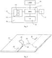
- FIG. 2 illustrates a control unit 10 according to some embodiments for adaptive power control for center 1 and ring beams 2 of a laser apparatus.
- the control unit is connected directly or indirectly to at least one laser unit 12.
- the control unit 10 may comprise a general-purpose computer provided with appropriate software for power control or the control unit may comprise a microcontroller.
- the control unit comprises at least one processor 11, which may be a single- or multi-core processor, wherein a single-core processor comprises one processing core and a multi-core processor comprises more than one processing core.
- the processor may comprise at least one application-specific integrated circuit, ASIC.
- the processor may be means for performing method steps in the device.
- the processor may be configured, at least in part by computer instructions, to perform presently illustrated beam profile power control features.
- the control unit device may comprise memory 13.
- the memory may comprise random-access memory and/or permanent memory.
- the memory may comprise at least one RAM chip.
- the memory may comprise solid-state, magnetic, optical and/or holographic memory, for example.
- the memory may be at least in part accessible to the processor.
- the memory may comprise computer instructions 14 that the processor 11 is configured to execute. When computer instructions configured to cause the processor to perform certain actions are stored in the memory, and the device in overall is configured to run under the direction of the processor using computer instructions from the memory, the processor and/or its at least one processing core may be considered to be configured to perform said certain actions.
- the memory 13 may be at least in part comprised in the processor.
- the memory 13 may be at least in part external to the device but accessible to the control unit device.
- the presently illustrated power control features may be caused by at least one computer program stored in the memory 13 and comprising instructions 14, when executed in the processor 11, to cause the processor to adaptively control the power densities of the laser beams by respective output control signals to the laser unit(s) 12.
- the memory 13 may also store various parameters 15 affecting power control by the processor, such as parameter sets defining different center and/or ring beam profiles and different cutting profiles and programs adjustable by an operator.
- the control unit device may comprise user interface, UI 16.
- the UI may comprise at least one of a display, a keyboard, a touchscreen, for example.
- the control unit may be arranged to control the power densities at least partly on the basis of user input, for example adapt the power density relation on the basis of user input regarding the workpiece.
- the control unit 10 may be connected also to one or more sensors 17, such as a sensor monitoring progress of the laser cutting operation and/or a sensor detecting properties of the workpiece being processed.
- the control unit 10 may comprise also other units, such as a transmitter and a receiver configured to transmit and receive information in accordance with at least one cellular or non-cellular standard.
- a first workpiece when a first workpiece is thinner than a second workpiece, higher proportion of the power density of the center beam 1 to that of the ring beam 2 is controlled for the first workpiece than for the second workpiece.
- relatively more power is controlled to the center beam 1 for cutting a thinner material, whereas the ring beam 2 is controlled relatively more power for a thicker material.
- the center beam 1 provided by the inner core of the multi-core optical fiber can produce a better beam quality than the ring beam 2 and can thus be controlled to provide very good quality cutting surface area for cutting thin materials and workpieces, or making piercing in cutting of thick materials.
- the disadvantages of a somewhat lower beam quality produced by the ring beam can be outweighed by the combined processing speed and cleanliness of the cutting surfaces due to the ring-like intensity distribution of the outer core.
- the power intensities of the inner and outer cores may be adjustable by the control unit 10 individually, and according to the current thickness of the workpiece and possible a set of other parameters associated with the cutting operation, by adjusting the power of the originating laser sources.
- the power density of the ring beam 2 may thus be controlled to increase more than the power density of the center beam 1 in response to an increase in the thickness of the workpiece.
- the use of the ring beam 2 enables to have good absorption in edge areas of a thicker material being cut, facilitating good cutting edge quality.
- the control unit 10 may be configured to cause piercing of the workpiece by specific power densities and relation between the center and ring beams, depending on the thickness of the workpiece. In some embodiments, both the center beam 1 and the ring beam 2 are controlled to cause the piercing. After the piercing, the control unit may control an optimal power density and relation between the center and ring beams for cutting operation.
- the control unit 10 may be configured to switch off the ring beam in response to the thickness of the workpiece falling under predetermined thickness limit value for switching off the ring laser beam.
- the limit value is selected from the range of 4 to 8 millimeters, in one embodiment 6 mm.
- Different power densities and relation between the center beam 1 and the ring beam 2 may be controlled depending on the material being cut.
- Above-illustrated embodiments for controlling the relation between the power densities of the center beam 1 and the ring beam 2 have been tested with good results. For example, for copper it has been detected that excellent cutting quality can be achieved by the presently disclosed arrangement by controlling -3:1 relation between the ring beam power density and the center beam power density, when the workpiece is 10 mm or more.
- cutting parameters such as cutting speed and diameters of the center and ring beams, that may affect the control of the power densities and the power density relation of the center beam 1 and the ring beam 2 for different workpiece thicknesses.
- Such other parameters may be controlled together with and in relation to the presently disclosed power control parameters.
- Figure 3 illustrates a cutting operation involving changes 22, 25 in cutting operation direction 23, 24, 26.
- the workpiece 21 is being cut according to a predetermined processing profile including changes of the cutting operation progression direction 23, 24, 26, referring generally to change of direction of advancement of processing/cutting action in the workpiece.
- the control unit 10 is configured to adapt the power density of the center beam 1 and/or the ring beam 2 in response to approaching the change point 22, 25 of the processing direction 23, 24, 26, that may also be referred to as the turning point.
- the power density in the center beam 1 and/or the ring beam 2 are controlled, according to the present invention, to reduce in connection with the movement of the laser head relative to the workpiece slowing down. Similarly, after the turning point 22, 25, when the laser head 20 is returning to the cutting progress as before approaching the turning point, the power densities are reinstated.
- the control unit 10 may decrease the power density of the ring beam 1 and/or center beam 2 for predetermined period in response to approaching a change point.
- the power control is based on the current cutting position in relation to the processing profile, i.e. at which position the laser head 20 is cutting the workpiece in relation to the current speed of the laser head relative to the workpiece. This enables to maintain high-quality cutting surfaces also in turning points where the laser head may slow down or stop temporarily.
- the power density of the ring beam 2 may be reduced in response to approaching the turning point 22, 25.
- the control unit 10 may switch off the center beam 1 at the turning point, and switch on the center beam 1 after the change point.
- the control unit 10 may reduce the power density(-ies) gradually when approaching the turning point 22, 25. Similarly, the power density(-ies) may be reinstated gradually after the turning point.
- the power density may be decreased or increased linearly with the decrease or increase of the speed of the processing head 20.
- control unit 10 is arranged to, in addition to the power density control, cause also other control operation affecting the composite laser beam 1, 2 around the discrepancy point in the cutting operation.
- control unit 10 is configured to control modulation of the center beam 1 and/or the ring beam 2 when approaching the change point 22 and/or in response to the change of the workpiece width.
- the control unit 10 may switch on modulation when approaching the change point.
- the state or parameters regarding the modulation before the turning point may be controlled when direct cutting is continued after the turning point.
- the present power control features in connection with processing direction change enable to compensate for the quality-deteriorating effects of the laser head slowing down before the turning point and then accelerating again.
- At least some of the presently disclosed embodiments may be applied for piercing and continuous cutting applications.
- the leading edge of the ring beam 2 in the direction of movement of a laser processing head causes a first intensity peak and the rear edge of the ring beam causes a second intensity peak.
- the elements are heated in stages and the intensity level of the rear and leading edge may be lower as compared to single center or spot beam to cause adequate action.
- the leading edge may also enable contaminant ablation. This enables to avoid sharp temperature change and avoid or at least reduce subsequent tempering and thus weaker areas caused by the sharp temperature change.
- the use of the ring beam in continuous cutting is also advantageous in avoiding spatter.
- a hybrid of center beam 1 and ring beam 2 may be generated by combining laser beams from originating laser devices and feed fibers in a multi-core optical fiber, from which a resulting composite laser beam with the center beam 1 and ring beam 2 may be directed to the workpiece.
- a first optical feed fiber may be aligned with a first core of the multi-core optical fiber and a second optical feed fiber may be aligned with a second core of said multi-core optical fiber.
- the first core of said multi-core optical fiber has a circular cross-section and the second core has an annular shape concentric to said first core.
- keyhole laser cutting is applied in combination with heat conduction cutting to provide dynamically adaptable center and ring laser beam profiles.
- Heat conduction cutting is applicable for cutting metal sheets typically up to a material thickness of approximately 2 mm.
- diode lasers of this kind have a power rating of 2 kW and a power density of well under 0.1 MW/cm 2 .
- a typical keyhole pattern caused by a high brightness laser, such as a fiber laser There is no practical limit to how thick metal sheets can be cut with such a laser, but it depends of course on the laser beam intensity and the processing speed, i.e.
- Fiber lasers may have a power rating of up to 1 - 10 kW or more, and a power intensity of several MW/cm 2.
- the diameter of the keyhole may be in the region of less than a millimeter, 0.1 millimeter for example, and the diameter of the spot may be in the region of several millimeters, such as 3 millimeters, for example.
- Fig. 4 shows one embodiment of an apparatus enabling independent center and ring beam power control and in which at least some of the above illustrated power control features may be applied.
- a high brightness fiber laser 30 is connected with an optical fiber 32 to a laser beam combiner 34.
- one or several solid state or diode lasers 31 are connected with a fiber 33 to the beam combiner 34.
- single laser beam combiners are known in the art. In this case the task of the combiner is to arrange all incoming laser beams so that they can be coupled to a dual core optical fiber 35.
- the hybrid nature of the laser is the result of having two laser beams propagating inside a single dual-core optical fiber 35.
- the two laser beams inside the fiber 35 have typically different brightness and intensity profiles, and may even have different wavelengths.
- the power levels in the two laser beams may be independently and continuously controlled by adjusting the power levels from the fiber laser 30 and solid state or diode laser 31.
- the high-brightness fiber laser 30 may consist of diode-pumped single or multiple fiber laser oscillator or master oscillator-power amplifier (MOPA) modules, each consisting of fiber-coupled diode lasers coupled to a fiber resonator, for example.
- MOPA master oscillator-power amplifier
- Further examples of high-brightness lasers are fiber-coupled thin-disc lasers or Nd-YAG lasers, which are pumped with light from diode lasers.
- Modern laser technology frequently relies on light as energy transfer medium, as many active solid-state light amplification materials are insulators. Diode lasers have replaced previously used flash lamps because of their higher efficiency and narrower light spectrum.
- the laser 31 is typically a fiber-coupled laser that may also comprise a solid-state laser resonator pumped by diode lasers, e.g. a thin-disc laser resonator (not shown).
- the dual core optical fiber 35 may be arranged to carry the laser beam from the fiber laser 30 in its center core and the beam generated by one or multiple second laser resonators 31 in an outer core which is arranged annularly around the center core, at a distance from the center core, see Fig. 6a .
- both first and second lasers may be fiber lasers, each having independently controllable power levels.
- both lasers 30 and 31 may be fiber lasers, in other embodiments any combination of fiber and solid-state or diode lasers, or both may be diode lasers.
- the purpose of the laser apparatus and the power ratings of the individual laser modules determine which kinds of lasers are feasible to be connected to the beam combiner 34.
- the dual core optical fiber is at its opposite end connected to a laser processing head 20 which guides a combined or composite laser beam 1, 2 onwards to a workpiece 21.
- the laser processing head 20 usually comprises collimating and focusing lenses (not shown) to produce an image of the intensity profile emerging from the end of the fiber 35 onto the workpiece 21 with a desired size, as determined by the focal lengths of the lenses.
- the task of the laser head 20 may also be to provide a pressurized gas jet to a cutting line. Pressurized gas also protects the optics within the laser head 20 from spitting molten metal, and also removes it from the cutting line helping to keep it clean.
- oxygen assist gas is applied at least in connection with cutting progression turning points, providing additional energy and enabling to further improve the cutting edge quality in these points.
- the apparatus is provided with a control unit 10.
- the control unit may also be integrated in one of the laser units 30 or 31. Alternatively, all units 30, 31 and 10 may be placed in a single housing and be integrated with each other in their construction, for convenience and reliability.
- the control unit 10 may be used to perform independent power control of the ring 2 and central 1 beams profile, and to enable dynamically adjustable ring-center beam which can be adjusted on-the-fly by applying at least some of the above-illustrated features.
- the control unit may be configured to control modulation of at least one of the laser units 30, 31. Preferably the modulation of the both laser beams can be dynamically controlled separately. Hence, a large variety of different cutting applications and purposes becomes possible by the same apparatus.
- the beam profile may be dynamically adjusted to fit variety of demands of challenging cutting types/applications, such as different materials, coatings and/or thicknesses.
- the control unit 10 may be arranged to receive feedback 36 from the user of the laser head 20, or automatic feedback e.g. from light intensity sensors. The feedback or input is then used to control the power of the lasers 30 and 31 to follow predetermined targets, or to adjust the laser power according to the resulting cutting result observed at the workpiece 21.
- the control unit 10, or another control unit may also control other functions of the apparatus, such as the movement of the laser processing head 20 in relation to the workpiece.
- the beam combiner 34 is made of fused silica components where optical power is propagating inside fused silica through the entire combiner structure, and the combiner has optical fibers at the input and output. Therefore, in the present invention the beam combiner 34 can be called an all-glass fiber combiner.
- Fig. 5 is shown the structure of a composite laser beam 40 emerging from the laser processing head to the workpiece 21.
- An annular outer ring beam 42 is carrying the laser power provided by laser device 31.
- an inner central beam 41 is carrying the laser power provided by fiber laser device 30, and will cause a keyhole pattern in the workpiece, due to its higher brightness.
- an annularly shaped zone 43 which provides only stray or no laser radiation at all.
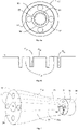
- Fig. 6a a cross-section of an example dual core optical fiber 50, having a central core 51 with a primary cladding 54.
- the outer core 53 is spatially formed by the inner cladding 54 and the outer cladding 55.
- the cladding is defined as a material having a lower refractive index than that of the core.
- the diameter of the central core 51 may be 70 ⁇ m, and the inner and outer diameters of the outer core 53 may be 100 ⁇ m and 180 ⁇ m, respectively.
- the central and peripheral cores 51 and 53 may also take other forms than those described above.
- the central core 51 may be of a square or rectangular shape, for instance.
- the peripheral core 53 may also have rectangular boundaries or be composed of multiple segments of linear or circular shapes.
- the laser radiation in the central core 51 of the dual core optical fiber 50 has a central and narrow spatial intensity profile, while the intensity distribution in the outer core 53 is taking the shape of a doughnut.
- This spatial intensity pattern is further imaged with processing optics in the laser head 20 onto the workpiece. With this configuration, the beam quality of the laser beam is relatively high both in the center and outer cores.
- FIG. 6b an example refractive index profile of an optical dual core fiber 50 is shown.
- the cores 51 and 53 have a refractive index n 51 and n 53 that is higher than the indexes n 54 and n 55 of the encircling materials 54 and 55 respectively.
- n 51 and n 53 that is higher than the indexes n 54 and n 55 of the encircling materials 54 and 55 respectively.
- the refractive index of fused silica can be adjusted by doping it with impurities. Doping fused silica with Germanium results in an increase of the refractive index, while doping it with Fluorine results in reduction of the refractive index. Therefore the cores 51 and 53 may be made of Ge-doped or undoped fused silica, and their primary claddings 54 and 55 of F-doped fused silica, for example.
- Fig. 7 is shown the key optical component 70 of the fiber combiner 34. It is a multi-bore capillary tube having a body portion consisting of a fused silica glass tube 77, an input end 76 for receiving laser beams (not shown) carried by optical feed fibers 71 and 72 from at least two laser devices (e.g. fibers 32 and 33 from devices 30 and 31). It also has an opposite output end 74 for delivering a composite output laser beam consisting of at least two laser beams aligned with each other in the same direction.
- laser devices e.g. fibers 32 and 33 from devices 30 and 31
- the optical feed fibers 71, 72 entering at the input end 76 extend through said body portion in capillary bores to said output end 74, and are fused with the glass tube 77 to form a component consisting of light guiding cores 71a, 72a and encircling glass material.
- the cores have refractive index that is higher than the refractive index of the encircling glass material around the cores to provide for propagation of optical power in the cores through the entire component by means of total internal reflection.
- the dimensions of the cores and the dimensions of the component 70 are not in scale, and for clarity, only a couple of the cores are shown with dashed lines.
- An optical component 70 may be manufactured by e.g. drawing.
- the smaller bores may have a diameter of about 150 ⁇ m, for example.
- the outside diameter of the capillary tube may be 1 mm.
- the material of the tube may be fused silica, for instance.
- the fibers, whose outer cladding of bulk glass (not shown) has preferably been etched away at least partly, are inserted into the middle bores and pushed through to a waist part 73 of the capillary taper. When the fibers are in place, the capillary tube 70 is heated at the waist section 73 to fuse the fibers to the tube and to form a first central light guiding core 72a and second light guiding cores 71a, which all extend through the optical component 70.
- the fibers 71, 72 may as an alternative have an inner core of pure fused silica material and an outer cladding of F- doped silica.
- the fused silica glass tube 77 of the optical component 70 may be manufactured from pure fused silica, because the light- guiding cores of the fibers are inherently surrounded by material with a lower refraction index. This means that the light remains in the cores 71a, 72a even if the refraction index of the capillary tube is the same as in the fiber cores.
- the outer fiber cladding of bulk glass may be etched away down to the F- doped cladding, or even further, as long as some F- doped cladding remains around the pure or Ge- doped inner fiber core.
- the fused cores 71a, 72a (shown with dashed lines) and tube 70 is then cut off or cleaved to create an end surface 74.
- a dual core fiber 35 like the one shown in Fig. 4 may then be welded to the capillary tube at the end 74, resulting in a seam 75.
- the center of the first optical feed fiber 72 is aligned with the center of the component 70, and the centers of, for example, four second optical feed fibers 71 are located to provide an output beam at the output end 74 at a predefined distance R from the first central light guiding core 72a.
- the number of second feed fibers is not as such limited, but instead 8, 16 or 32 instead of 4, for example.
- the second light guiding cores 71a are preferably arranged symmetrically with respect to the central core 72a, to provide output beams with an angular distance of 90° between each other.
- the presently disclosed laser cutting method and apparatus may be applied in a large variety of applications. Particular advantages are achieved in applications where there is need to achieve excellent cutting surface quality for laser-cutting materials with differing properties, such as thicknesses, and/or changing and multiform cutting operations.
- a single cutting apparatus may now be used for these varying properties/requirements, enabling to instantly adapt to optimal cutting beam profile accordingly.
- the present system can be particularly advantageous for cutting needs of automobile industry.
Landscapes
- Physics & Mathematics (AREA)
- Optics & Photonics (AREA)
- Engineering & Computer Science (AREA)
- Plasma & Fusion (AREA)
- Mechanical Engineering (AREA)
- General Physics & Mathematics (AREA)
- Laser Beam Processing (AREA)
Claims (14)
- Appareil de traitement au laser comprenant :- au moins un premier dispositif laser (30), chaque premier dispositif laser connecté à au moins une première fibre d'alimentation optique (32) pour délivrer un premier faisceau laser ;- au moins un second dispositif laser (31), chaque second dispositif laser connecté à au moins une seconde fibre d'alimentation optique (33) pour délivrer un second faisceau laser ;et caractérisé par ce qui suit :- des moyens de combinaison de faisceaux (34) connectés auxdites première et seconde fibres d'alimentation et à une fibre optique à cœurs multiples (35 ; 50), les moyens de combinaison étant adaptés pour former un faisceau laser composite en alignant ladite au moins une première fibre d'alimentation optique (72 ; 56) sur un premier cœur (51) de ladite fibre optique à cœurs multiples (50) et ladite au moins une seconde fibre d'alimentation optique (71 ; 57) sur au moins un second cœur (53) de ladite fibre optique à cœurs multiples (50), dans lequel ledit premier cœur (51) de ladite fibre optique à cœurs multiples (50) présente une coupe transversale circulaire, ledit second cœur (53) présente une forme annulaire concentrique avec ledit premier cœur, et les moyens de combinaison de faisceaux comprennent un tube capillaire à alésages multiples présentant une partie corps comprenant un tube de verre (77), une extrémité d'entrée (76) pour recevoir des faisceaux laser transportés par lesdites fibres d'alimentation optique, et une extrémité de sortie opposée (74) pour délivrer le faisceau laser de sortie composite, dans lequel lesdites fibres d'alimentation optique pénétrant à l'extrémité d'entrée s'étendent à travers la partie corps dans des alésages de capillaires jusqu'à l'extrémité de sortie, fusionnent avec le tube de verre pour former un élément consistant en des cœurs de guidage de lumière (71a, 72a) et encerclant un matériau de verre ;- lesdits premier et second cœurs pouvant être connectés à une tête de traitement au laser (20), pour diriger un faisceau laser composite (40) comprenant un premier faisceau laser de sortie (1) et un second faisceau laser de sortie (2) de la tête de traitement au laser (20) à une pièce (21) devant être coupée, dans lequel le premier faisceau laser de sortie présente une coupe transversale circulaire et le second faisceau laser de sortie (2) présente une coupe transversale annulaire espacée du et concentrique avec le premier faisceau de sortie laser (1) au niveau de la pièce (21) ; et- une unité de commande (10) connectée fonctionnellement auxdits premier et second dispositifs laser (30, 31), pour commander individuellement la densité de puissance dans lesdits premier et second faisceaux laser de sortie (1, 2), dans lequel l'unité de commande est configurée pour adapter la densité de puissance d'au moins un des premier et second faisceaux laser (1, 2) en réponse à l'approche d'un point de changement (22) dans une direction de progression de coupe, et pour adapter la densité de puissance conformément à la vitesse de la tête de traitement au laser par rapport à la pièce.
- Appareil selon la revendication 1, dans lequel l'appareil est configuré pour traiter la pièce conformément à un profil de traitement prédéterminé incluant au moins un changement de direction de progression d'opération de coupe, et dans lequel l'unité de commande est configurée pour adapter la densité de puissance d'au moins un desdits premier et second faisceaux laser de sortie (1, 2) sur la base de la position de coupe courante par rapport au profil de traitement.
- Appareil selon la revendication 2, dans lequel l'unité de commande est configurée pour réduire la densité de puissance du premier faisceau laser de sortie progressivement lors de l'approche du point de changement (22).
- Appareil selon la revendication 2, dans lequel l'unité de commande est configurée pour éteindre ledit premier faisceau laser (1) en réponse à la tête de traitement au laser approchant du point de changement et allumer ledit premier faisceau laser de sortie (1) après le point de changement.
- Appareil selon la revendication 2, dans lequel l'unité de commande est configurée pour changer la modulation d'au moins un des premier et second faisceaux laser de sortie (1, 2) lors de l'approche du point de changement (22) et/ou en réponse à un changement d'épaisseur de la pièce.
- Appareil selon une quelconque revendication précédente, dans lequel l'unité de commande est configurée pour provoquer un perçage de la pièce à la fois par ledit premier faisceau laser de sortie et ledit second faisceau laser de sortie.
- Appareil selon une quelconque revendication précédente, dans lequel l'unité de commande est configurée pour éteindre ledit second faisceau laser de sortie (2) en réponse à l'épaisseur de la pièce tombant en dessous d'une valeur de limite d'épaisseur prédéterminée pour éteindre un faisceau laser annulaire.
- Appareil selon une quelconque revendication précédente, dans lequel l'unité de commande est configurée pour changer une largeur d'impulsions et/ou une fréquence d'impulsions lumineuses d'au moins un du premier dispositif laser et du second dispositif laser pour commander la densité de puissance d'au moins un des premier et second faisceaux laser de sortie.
- Appareil selon une quelconque revendication précédente, dans lequel un capteur (17) pour détecter une épaisseur de la pièce est connecté à l'unité de commande, et l'unité de commande est configurée pour adapter une relation des densités de puissance sur la base d'une sortie de capteur reçue indiquant une épaisseur de la pièce (21).
- Procédé de coupe d'une pièce avec un faisceau laser, comprenant :- une fourniture d'au moins un premier faisceau laser à partir d'au moins une première fibre d'alimentation optique (32) connectée à au moins un premier dispositif laser (30);et étant caractérisé par ce qui suit :- une fourniture d'au moins un second faisceau laser à partir d'au moins une seconde fibre d'alimentation optique (33) connectée à au moins un second dispositif laser (31) ;- une combinaison desdits premier et second faisceaux laser dans une fibre optique à cœurs multiples (35 ; 50), pour former un faisceau laser composite en alignant ladite au moins une première fibre d'alimentation optique sur un premier cœur (51) de ladite fibre optique à cœurs multiples et ladite au moins une seconde fibre d'alimentation optique sur un second cœur (53) de ladite fibre optique à cœurs multiples ; dans lequel ledit premier cœur (51) de ladite fibre optique à cœurs multiples présente une coupe transversale circulaire, et ledit second cœur (53) présente une forme annulaire concentrique avec ledit premier cœur, et dans lequel lesdits premier et second faisceaux laser sont combinés par un combineur de faisceaux (34) comprenant un tube capillaire à alésages multiples présentant une partie corps comprenant un tube de verre (77), une extrémité d'entrée (76) pour recevoir des faisceaux laser transportés par lesdites fibres d'alimentation optique, et une extrémité de sortie opposée (74) pour délivrer le faisceau laser de sortie composite, dans lequel lesdites fibres d'alimentation optique pénétrant à l'extrémité d'entrée s'étendent à travers la partie corps dans des alésages de capillaires jusqu'à l'extrémité de sortie, fusionnent avec le tube de verre pour former un élément consistant en des cœurs de guidage de lumière (71a, 72a) et encerclant un matériau de verre ;- une direction d'un faisceau laser composite comprenant un premier faisceau laser de sortie (1) et un second faisceau laser de sortie (2) d'une tête de traitement au laser (20), connectée à ladite fibre optique à cœurs multiples (12 ; 50), à une pièce (21) devant être coupée, dans lequel le premier faisceau laser de sortie présente une coupe transversale circulaire et le second faisceau laser de sortie (2) présente une coupe transversale annulaire espacée du et concentrique avec le premier faisceau laser de sortie (1) au niveau de la pièce (21) ; et- une commande, par une unité de commande (10), d'une densité de puissance individuellement dans lesdits premier et second faisceaux laser de sortie (1, 2), dans lequel la densité de puissance d'au moins un des premier et second faisceaux laser de sortie (1, 2) est adaptée en réponse à l'approche d'un point de changement (22) dans une direction de progression de coupe et conformément à la vitesse de la tête de traitement au laser par rapport à la pièce.
- Procédé selon la revendication 10, dans lequel la pièce (21) est traitée conformément à un profil de traitement prédéterminé incluant au moins un changement de direction de progression d'opération de coupe, et la densité de puissance d'au moins un desdits premier et second faisceaux laser de sortie (1, 2) est adaptée sur la base de la position de coupe courante par rapport au profil de traitement.
- Procédé selon la revendication 11, dans lequel la densité de puissance dudit premier faisceau laser de sortie (2) est réduite en réponse à l'approche du point de changement (22).
- Procédé selon la revendication 11, dans lequel ledit premier faisceau laser de sortie (1) est éteint en réponse à une tête de traitement au laser approchant du point de changement (22) et ledit premier faisceau laser de sortie est allumé après le point de changement.
- Procédé selon la revendication 11, dans lequel la modulation d'au moins un des premier et second faisceaux laser de sortie (1, 2) est changée en réponse à l'approche du point de changement et/ou en réponse à un changement d'épaisseur de la pièce.
Applications Claiming Priority (1)
| Application Number | Priority Date | Filing Date | Title |
|---|---|---|---|
| PCT/FI2016/050855 WO2018104575A1 (fr) | 2016-12-08 | 2016-12-08 | Appareil et procédé de traitement au laser |
Publications (3)
| Publication Number | Publication Date |
|---|---|
| EP3551372A1 EP3551372A1 (fr) | 2019-10-16 |
| EP3551372A4 EP3551372A4 (fr) | 2020-09-09 |
| EP3551372B1 true EP3551372B1 (fr) | 2022-09-14 |
Family
ID=62492239
Family Applications (1)
| Application Number | Title | Priority Date | Filing Date |
|---|---|---|---|
| EP16923523.1A Active EP3551372B1 (fr) | 2016-12-08 | 2016-12-08 | Appareil de traitement au laser, et procédé de découpe d'une pièce par un faisceau laser |
Country Status (7)
| Country | Link |
|---|---|
| US (1) | US11022747B2 (fr) |
| EP (1) | EP3551372B1 (fr) |
| JP (1) | JP6887502B2 (fr) |
| KR (1) | KR102636850B1 (fr) |
| CN (1) | CN110087817B (fr) |
| TW (1) | TWI758365B (fr) |
| WO (1) | WO2018104575A1 (fr) |
Families Citing this family (35)
| Publication number | Priority date | Publication date | Assignee | Title |
|---|---|---|---|---|
| KR102418512B1 (ko) * | 2017-12-29 | 2022-07-07 | 코렐라스 오와이 | 레이저 프로세싱 장치 및 방법 |
| JP7470639B2 (ja) * | 2018-09-04 | 2024-04-18 | 古河電気工業株式会社 | 溶接方法および溶接装置 |
| WO2020101970A1 (fr) * | 2018-11-12 | 2020-05-22 | Panasonic intellectual property Management co., Ltd | Structures à fibres optiques et procédés de mise en forme de faisceau |
| IT201800021538A1 (it) | 2018-12-31 | 2020-07-01 | Prima Electro S P A | Apparato per combinazione di fasci laser in fibre ottiche e procedimento corrispondente |
| EP3924136B1 (fr) | 2019-02-13 | 2023-04-26 | Coherent, Inc. | Procédé de soudage laser |
| CN109687271A (zh) * | 2019-02-22 | 2019-04-26 | 深圳市杰普特光电股份有限公司 | 光纤激光器及激光材料加工系统 |
| PL3914418T3 (pl) * | 2019-02-25 | 2022-06-13 | Wsoptics Technologies Gmbh | Sposób obróbki strumieniowo-ściernej przedmiotu obrabianego w kształcie płyty lub rury |
| GB2582331A (en) * | 2019-03-19 | 2020-09-23 | Spi Lasers Uk Ltd | Apparatus for laser processing a material |
| US11719897B2 (en) * | 2019-03-28 | 2023-08-08 | Panasonic Intellectual Property Management Co., Ltd. | Material processing utilizing high-frequency beam shaping |
| CN110320593B (zh) * | 2019-07-12 | 2020-06-23 | 武汉锐科光纤激光技术股份有限公司 | 一种光纤激光耦合器 |
| US11005227B2 (en) | 2019-09-05 | 2021-05-11 | Nufern | Multi-wavelength adjustable-radial-mode fiber laser |
| US20210069834A1 (en) * | 2019-09-11 | 2021-03-11 | Curio Holding Company | Method, device, and system for protecting a touch screen |
| DE102020200798A1 (de) | 2020-01-23 | 2021-07-29 | Trumpf Werkzeugmaschinen Gmbh + Co. Kg | Verfahren und Vorrichtung zur Lasermaterialbearbeitung mittels eines in seinem Leistungsprofil verstellbaren Bearbeitungslaserstrahls |
| CN113478074A (zh) * | 2020-03-17 | 2021-10-08 | 深圳市联赢激光股份有限公司 | 一种激光装置 |
| CN113399825B (zh) * | 2020-03-17 | 2022-05-20 | 深圳市联赢激光股份有限公司 | 一种激光装置 |
| DE102020205948A1 (de) | 2020-05-12 | 2021-11-18 | Trumpf Laser- Und Systemtechnik Gmbh | Laserschneidverfahren und Laserschneidanlage |
| US11524361B2 (en) | 2020-05-22 | 2022-12-13 | Coherent, Inc. | Laser welding method |
| CN113794091B (zh) * | 2020-05-25 | 2023-07-18 | 深圳市创鑫激光股份有限公司 | 一种激光器和多波长输出激光加工系统 |
| JP2023534644A (ja) * | 2020-07-07 | 2023-08-10 | パナソニックIpマネジメント株式会社 | ビーム形状及び強度を変更するためのステップコアファイバ構造及び方法 |
| DE102020128186A1 (de) * | 2020-10-27 | 2022-04-28 | Trumpf Werkzeugmaschinen Gmbh + Co. Kg | Verfahren und Vorrichtung zum Laserschneiden mittels eines in einer Multikernfaser geführten Laserstrahls sowie zugehöriges Computerprogrammprodukt |
| CN113140951B (zh) * | 2021-04-06 | 2022-09-06 | 华中科技大学 | 一种环形激光输出器件 |
| DE102021108759A1 (de) | 2021-04-08 | 2022-10-13 | Trumpf Werkzeugmaschinen Gmbh + Co. Kg | Vorrichtung und Verfahren zur Polarisation eines Laserstrahls, der einen undefinierten Polarisationszustand aufweist |
| JP7394088B2 (ja) * | 2021-05-13 | 2023-12-07 | 三菱電線工業株式会社 | レーザ加工用光ファイバ |
| CN113210893B (zh) * | 2021-05-20 | 2022-08-30 | 武汉锐科光纤激光技术股份有限公司 | 一种复合激光打孔方法及激光打孔装置 |
| DE102021115036A1 (de) * | 2021-06-10 | 2022-12-15 | Precitec Gmbh & Co. Kg | Verfahren zur Laserbearbeitung eines Werkstücks und dazugehöriges Laserbearbeitungssystem |
| AT525314B1 (de) * | 2021-07-22 | 2023-10-15 | Trotec Laser Gmbh | Verfahren zum Erzeugen einer Perforierung an einem Werkstück für unterschiedliche Lasermaschinen |
| CN114101942A (zh) * | 2021-11-29 | 2022-03-01 | 武汉锐科光纤激光技术股份有限公司 | 材料切割的控制方法、设备、装置、存储介质及电子装置 |
| CN114043089B (zh) * | 2021-12-10 | 2022-05-17 | 哈尔滨工业大学 | 一种t型接头点环激光双侧同步焊接方法 |
| JP2025509310A (ja) * | 2022-03-07 | 2025-04-11 | アイピージー フォトニクス コーポレーション | 動的に制御されたレーザ穴開けシステムおよび穴を生成する方法 |
| KR20250027750A (ko) * | 2022-06-29 | 2025-02-27 | 트럼프 레이저 유케이 리미티드 | 재료를 레이저 가공하기 위한 장치 |
| EP4501526A4 (fr) * | 2022-08-10 | 2025-07-09 | Yamazaki Mazak Corp | Procédé de perçage au laser et machine laser |
| US12560808B2 (en) * | 2023-01-06 | 2026-02-24 | Mloptic Corp. | Waveguide calibration |
| US11709325B1 (en) * | 2023-01-06 | 2023-07-25 | Mloptic Corp. | Waveguide calibration |
| KR20240111595A (ko) * | 2023-01-10 | 2024-07-17 | 주식회사 엘지에너지솔루션 | 전극 제조 장치 및 방법 |
| DE102023134096A1 (de) | 2023-12-06 | 2025-06-12 | TRUMPF Laser- und Systemtechnik SE | Lasereinrichtung und Verfahren zum Bearbeiten mindestens eines Werkstücks mittels mindestens eines Laserstrahls |
Family Cites Families (29)
| Publication number | Priority date | Publication date | Assignee | Title |
|---|---|---|---|---|
| JPS58159514A (ja) * | 1982-03-18 | 1983-09-21 | Toshiba Corp | レ−ザビ−ム空間分布形成方法 |
| JPH01197084A (ja) * | 1988-01-29 | 1989-08-08 | Fanuc Ltd | Cncレーザ加工機のパワー制御方式 |
| JPH03238184A (ja) * | 1990-02-15 | 1991-10-23 | Nec Corp | レーザ加工法 |
| JPH067973A (ja) | 1992-06-25 | 1994-01-18 | Fanuc Ltd | レーザ加工装置 |
| JP3531199B2 (ja) | 1994-02-22 | 2004-05-24 | 三菱電機株式会社 | 光伝送装置 |
| JP3768730B2 (ja) | 1999-06-14 | 2006-04-19 | 松下電器産業株式会社 | レーザ加工機およびその数値制御装置ならびにレーザ加工機の制御方法 |
| WO2002080081A1 (fr) * | 2001-03-29 | 2002-10-10 | Lasx Industries, Inc. | Controleur de laser utilisant des modeles predictifs d'un systeme de traitement de materiaux |
| JP2004105972A (ja) * | 2002-09-13 | 2004-04-08 | Mitsubishi Heavy Ind Ltd | レーザ切断加工システム |
| JP4267378B2 (ja) * | 2003-06-11 | 2009-05-27 | トヨタ自動車株式会社 | 樹脂部材のレーザ溶着方法及びその装置およびレーザ溶着部材 |
| GB0328370D0 (en) | 2003-12-05 | 2004-01-14 | Southampton Photonics Ltd | Apparatus for providing optical radiation |
| JP2007196254A (ja) | 2006-01-25 | 2007-08-09 | Fanuc Ltd | レーザ加工方法 |
| JP4795886B2 (ja) * | 2006-07-27 | 2011-10-19 | 株式会社キーエンス | レーザ加工装置、レーザ加工条件設定装置、レーザ加工条件設定方法、レーザ加工条件設定プログラム |
| WO2009077637A1 (fr) * | 2007-12-14 | 2009-06-25 | Corelase Oy | Procédé et dispositif relatifs à des fibres optiques |
| GB2460648A (en) * | 2008-06-03 | 2009-12-09 | M Solv Ltd | Method and apparatus for laser focal spot size control |
| KR20130059337A (ko) * | 2010-03-30 | 2013-06-05 | 아이엠알에이 아메리카, 인코포레이티드. | 레이저 기반 재료 가공 장치 및 방법들 |
| DE102010003750A1 (de) * | 2010-04-08 | 2011-10-13 | Trumpf Laser- Und Systemtechnik Gmbh | Verfahren und Anordnung zum Verändern der Strahlprofilcharakteristik eines Laserstrahls mittels einer Mehrfachclad-Faser |
| US9403238B2 (en) * | 2011-09-21 | 2016-08-02 | Align Technology, Inc. | Laser cutting |
| JP5923765B2 (ja) * | 2011-10-07 | 2016-05-25 | 株式会社ブイ・テクノロジー | ガラス基板のレーザ加工装置 |
| WO2013086227A1 (fr) * | 2011-12-09 | 2013-06-13 | Jds Uniphase Corporation | Variation du produit des paramètres d'un faisceau laser |
| JP2013180295A (ja) * | 2012-02-29 | 2013-09-12 | Mitsubishi Heavy Ind Ltd | 加工装置及び加工方法 |
| JP2013235139A (ja) | 2012-05-09 | 2013-11-21 | Furukawa Electric Co Ltd:The | 光ファイバ接続構造、光増幅器の励起光制御方法 |
| JP2014013354A (ja) * | 2012-07-05 | 2014-01-23 | Hitachi Cable Ltd | マルチコアインタフェース及びその製造方法 |
| JP5990419B2 (ja) | 2012-07-09 | 2016-09-14 | 株式会社フジクラ | 光学入出力デバイス |
| JP2014018800A (ja) | 2012-07-12 | 2014-02-03 | Miyachi Technos Corp | レーザ接合方法及びレーザ接合システム |
| GB2510370A (en) * | 2013-01-31 | 2014-08-06 | Gsi Group Ltd | Fibre Optical Laser Combiner |
| JP5460917B1 (ja) | 2013-11-08 | 2014-04-02 | 坂口電熱株式会社 | レーザ加熱装置 |
| CN105720463B (zh) * | 2014-08-01 | 2021-05-14 | 恩耐公司 | 光纤和光纤传输的激光器中的背向反射保护与监控 |
| WO2016198724A2 (fr) * | 2015-06-09 | 2016-12-15 | Corelase Oy | Appareil et procédé de traitement au laser et composant optique destiné à ceux-ci |
| ES2782114T3 (es) * | 2016-07-15 | 2020-09-10 | Corelase Oy | Aparato y método de tratamiento láser |
-
2016
- 2016-12-08 CN CN201680091463.0A patent/CN110087817B/zh active Active
- 2016-12-08 JP JP2019530826A patent/JP6887502B2/ja active Active
- 2016-12-08 WO PCT/FI2016/050855 patent/WO2018104575A1/fr not_active Ceased
- 2016-12-08 EP EP16923523.1A patent/EP3551372B1/fr active Active
- 2016-12-08 US US16/464,310 patent/US11022747B2/en active Active
- 2016-12-08 KR KR1020197019651A patent/KR102636850B1/ko active Active
-
2017
- 2017-12-05 TW TW106142463A patent/TWI758365B/zh active
Also Published As
| Publication number | Publication date |
|---|---|
| WO2018104575A1 (fr) | 2018-06-14 |
| EP3551372A1 (fr) | 2019-10-16 |
| JP2020513325A (ja) | 2020-05-14 |
| US11022747B2 (en) | 2021-06-01 |
| CN110087817A (zh) | 2019-08-02 |
| KR102636850B1 (ko) | 2024-02-14 |
| KR20190093622A (ko) | 2019-08-09 |
| TWI758365B (zh) | 2022-03-21 |
| US20190383998A1 (en) | 2019-12-19 |
| TW201825217A (zh) | 2018-07-16 |
| CN110087817B (zh) | 2022-05-17 |
| EP3551372A4 (fr) | 2020-09-09 |
| JP6887502B2 (ja) | 2021-06-16 |
Similar Documents
| Publication | Publication Date | Title |
|---|---|---|
| EP3551372B1 (fr) | Appareil de traitement au laser, et procédé de découpe d'une pièce par un faisceau laser | |
| US12447553B2 (en) | Laser processing apparatus and method | |
| EP3285956B1 (fr) | Appareil et procédé de traitement au laser | |
| EP3308202B1 (fr) | Appareil et procédé de traitement au laser et composant optique destiné à ceux-ci |
Legal Events
| Date | Code | Title | Description |
|---|---|---|---|
| STAA | Information on the status of an ep patent application or granted ep patent |
Free format text: STATUS: THE INTERNATIONAL PUBLICATION HAS BEEN MADE |
|
| PUAI | Public reference made under article 153(3) epc to a published international application that has entered the european phase |
Free format text: ORIGINAL CODE: 0009012 |
|
| STAA | Information on the status of an ep patent application or granted ep patent |
Free format text: STATUS: REQUEST FOR EXAMINATION WAS MADE |
|
| 17P | Request for examination filed |
Effective date: 20190604 |
|
| AK | Designated contracting states |
Kind code of ref document: A1 Designated state(s): AL AT BE BG CH CY CZ DE DK EE ES FI FR GB GR HR HU IE IS IT LI LT LU LV MC MK MT NL NO PL PT RO RS SE SI SK SM TR |
|
| AX | Request for extension of the european patent |
Extension state: BA ME |
|
| DAV | Request for validation of the european patent (deleted) | ||
| DAX | Request for extension of the european patent (deleted) | ||
| REG | Reference to a national code |
Ref country code: DE Ref legal event code: R079 Ref document number: 602016075085 Country of ref document: DE Free format text: PREVIOUS MAIN CLASS: B23K0026030000 Ipc: B23K0026073000 |
|
| A4 | Supplementary search report drawn up and despatched |
Effective date: 20200807 |
|
| RIC1 | Information provided on ipc code assigned before grant |
Ipc: B23K 26/06 20140101ALI20200803BHEP Ipc: G02B 6/02 20060101ALI20200803BHEP Ipc: G02B 6/036 20060101ALI20200803BHEP Ipc: B23K 26/38 20140101ALI20200803BHEP Ipc: B23K 26/073 20060101AFI20200803BHEP Ipc: G02B 6/28 20060101ALI20200803BHEP |
|
| STAA | Information on the status of an ep patent application or granted ep patent |
Free format text: STATUS: EXAMINATION IS IN PROGRESS |
|
| 17Q | First examination report despatched |
Effective date: 20210629 |
|
| GRAP | Despatch of communication of intention to grant a patent |
Free format text: ORIGINAL CODE: EPIDOSNIGR1 |
|
| STAA | Information on the status of an ep patent application or granted ep patent |
Free format text: STATUS: GRANT OF PATENT IS INTENDED |
|
| INTG | Intention to grant announced |
Effective date: 20220314 |
|
| GRAS | Grant fee paid |
Free format text: ORIGINAL CODE: EPIDOSNIGR3 |
|
| GRAA | (expected) grant |
Free format text: ORIGINAL CODE: 0009210 |
|
| STAA | Information on the status of an ep patent application or granted ep patent |
Free format text: STATUS: THE PATENT HAS BEEN GRANTED |
|
| AK | Designated contracting states |
Kind code of ref document: B1 Designated state(s): AL AT BE BG CH CY CZ DE DK EE ES FI FR GB GR HR HU IE IS IT LI LT LU LV MC MK MT NL NO PL PT RO RS SE SI SK SM TR |
|
| REG | Reference to a national code |
Ref country code: GB Ref legal event code: FG4D |
|
| REG | Reference to a national code |
Ref country code: CH Ref legal event code: EP |
|
| REG | Reference to a national code |
Ref country code: DE Ref legal event code: R096 Ref document number: 602016075085 Country of ref document: DE |
|
| REG | Reference to a national code |
Ref country code: IE Ref legal event code: FG4D |
|
| REG | Reference to a national code |
Ref country code: AT Ref legal event code: REF Ref document number: 1518408 Country of ref document: AT Kind code of ref document: T Effective date: 20221015 |
|
| REG | Reference to a national code |
Ref country code: LT Ref legal event code: MG9D |
|
| REG | Reference to a national code |
Ref country code: NL Ref legal event code: MP Effective date: 20220914 |
|
| PG25 | Lapsed in a contracting state [announced via postgrant information from national office to epo] |
Ref country code: SE Free format text: LAPSE BECAUSE OF FAILURE TO SUBMIT A TRANSLATION OF THE DESCRIPTION OR TO PAY THE FEE WITHIN THE PRESCRIBED TIME-LIMIT Effective date: 20220914 Ref country code: RS Free format text: LAPSE BECAUSE OF FAILURE TO SUBMIT A TRANSLATION OF THE DESCRIPTION OR TO PAY THE FEE WITHIN THE PRESCRIBED TIME-LIMIT Effective date: 20220914 Ref country code: NO Free format text: LAPSE BECAUSE OF FAILURE TO SUBMIT A TRANSLATION OF THE DESCRIPTION OR TO PAY THE FEE WITHIN THE PRESCRIBED TIME-LIMIT Effective date: 20221214 Ref country code: LV Free format text: LAPSE BECAUSE OF FAILURE TO SUBMIT A TRANSLATION OF THE DESCRIPTION OR TO PAY THE FEE WITHIN THE PRESCRIBED TIME-LIMIT Effective date: 20220914 Ref country code: LT Free format text: LAPSE BECAUSE OF FAILURE TO SUBMIT A TRANSLATION OF THE DESCRIPTION OR TO PAY THE FEE WITHIN THE PRESCRIBED TIME-LIMIT Effective date: 20220914 |
|
| REG | Reference to a national code |
Ref country code: AT Ref legal event code: MK05 Ref document number: 1518408 Country of ref document: AT Kind code of ref document: T Effective date: 20220914 |
|
| PG25 | Lapsed in a contracting state [announced via postgrant information from national office to epo] |
Ref country code: HR Free format text: LAPSE BECAUSE OF FAILURE TO SUBMIT A TRANSLATION OF THE DESCRIPTION OR TO PAY THE FEE WITHIN THE PRESCRIBED TIME-LIMIT Effective date: 20220914 Ref country code: GR Free format text: LAPSE BECAUSE OF FAILURE TO SUBMIT A TRANSLATION OF THE DESCRIPTION OR TO PAY THE FEE WITHIN THE PRESCRIBED TIME-LIMIT Effective date: 20221215 |
|
| PG25 | Lapsed in a contracting state [announced via postgrant information from national office to epo] |
Ref country code: SM Free format text: LAPSE BECAUSE OF FAILURE TO SUBMIT A TRANSLATION OF THE DESCRIPTION OR TO PAY THE FEE WITHIN THE PRESCRIBED TIME-LIMIT Effective date: 20220914 Ref country code: RO Free format text: LAPSE BECAUSE OF FAILURE TO SUBMIT A TRANSLATION OF THE DESCRIPTION OR TO PAY THE FEE WITHIN THE PRESCRIBED TIME-LIMIT Effective date: 20220914 Ref country code: PT Free format text: LAPSE BECAUSE OF FAILURE TO SUBMIT A TRANSLATION OF THE DESCRIPTION OR TO PAY THE FEE WITHIN THE PRESCRIBED TIME-LIMIT Effective date: 20230116 Ref country code: ES Free format text: LAPSE BECAUSE OF FAILURE TO SUBMIT A TRANSLATION OF THE DESCRIPTION OR TO PAY THE FEE WITHIN THE PRESCRIBED TIME-LIMIT Effective date: 20220914 Ref country code: CZ Free format text: LAPSE BECAUSE OF FAILURE TO SUBMIT A TRANSLATION OF THE DESCRIPTION OR TO PAY THE FEE WITHIN THE PRESCRIBED TIME-LIMIT Effective date: 20220914 Ref country code: AT Free format text: LAPSE BECAUSE OF FAILURE TO SUBMIT A TRANSLATION OF THE DESCRIPTION OR TO PAY THE FEE WITHIN THE PRESCRIBED TIME-LIMIT Effective date: 20220914 |
|
| PG25 | Lapsed in a contracting state [announced via postgrant information from national office to epo] |
Ref country code: SK Free format text: LAPSE BECAUSE OF FAILURE TO SUBMIT A TRANSLATION OF THE DESCRIPTION OR TO PAY THE FEE WITHIN THE PRESCRIBED TIME-LIMIT Effective date: 20220914 Ref country code: PL Free format text: LAPSE BECAUSE OF FAILURE TO SUBMIT A TRANSLATION OF THE DESCRIPTION OR TO PAY THE FEE WITHIN THE PRESCRIBED TIME-LIMIT Effective date: 20220914 Ref country code: IS Free format text: LAPSE BECAUSE OF FAILURE TO SUBMIT A TRANSLATION OF THE DESCRIPTION OR TO PAY THE FEE WITHIN THE PRESCRIBED TIME-LIMIT Effective date: 20230114 Ref country code: EE Free format text: LAPSE BECAUSE OF FAILURE TO SUBMIT A TRANSLATION OF THE DESCRIPTION OR TO PAY THE FEE WITHIN THE PRESCRIBED TIME-LIMIT Effective date: 20220914 |
|
| REG | Reference to a national code |
Ref country code: DE Ref legal event code: R097 Ref document number: 602016075085 Country of ref document: DE |
|
| PG25 | Lapsed in a contracting state [announced via postgrant information from national office to epo] |
Ref country code: NL Free format text: LAPSE BECAUSE OF FAILURE TO SUBMIT A TRANSLATION OF THE DESCRIPTION OR TO PAY THE FEE WITHIN THE PRESCRIBED TIME-LIMIT Effective date: 20220914 Ref country code: AL Free format text: LAPSE BECAUSE OF FAILURE TO SUBMIT A TRANSLATION OF THE DESCRIPTION OR TO PAY THE FEE WITHIN THE PRESCRIBED TIME-LIMIT Effective date: 20220914 |
|
| PLBE | No opposition filed within time limit |
Free format text: ORIGINAL CODE: 0009261 |
|
| STAA | Information on the status of an ep patent application or granted ep patent |
Free format text: STATUS: NO OPPOSITION FILED WITHIN TIME LIMIT |
|
| PG25 | Lapsed in a contracting state [announced via postgrant information from national office to epo] |
Ref country code: DK Free format text: LAPSE BECAUSE OF FAILURE TO SUBMIT A TRANSLATION OF THE DESCRIPTION OR TO PAY THE FEE WITHIN THE PRESCRIBED TIME-LIMIT Effective date: 20220914 |
|
| REG | Reference to a national code |
Ref country code: CH Ref legal event code: PL |
|
| P01 | Opt-out of the competence of the unified patent court (upc) registered |
Effective date: 20230625 |
|
| 26N | No opposition filed |
Effective date: 20230615 |
|
| REG | Reference to a national code |
Ref country code: BE Ref legal event code: MM Effective date: 20221231 |
|
| PG25 | Lapsed in a contracting state [announced via postgrant information from national office to epo] |
Ref country code: SI Free format text: LAPSE BECAUSE OF FAILURE TO SUBMIT A TRANSLATION OF THE DESCRIPTION OR TO PAY THE FEE WITHIN THE PRESCRIBED TIME-LIMIT Effective date: 20220914 Ref country code: LU Free format text: LAPSE BECAUSE OF NON-PAYMENT OF DUE FEES Effective date: 20221208 |
|
| PG25 | Lapsed in a contracting state [announced via postgrant information from national office to epo] |
Ref country code: LI Free format text: LAPSE BECAUSE OF NON-PAYMENT OF DUE FEES Effective date: 20221231 Ref country code: IE Free format text: LAPSE BECAUSE OF NON-PAYMENT OF DUE FEES Effective date: 20221208 Ref country code: CH Free format text: LAPSE BECAUSE OF NON-PAYMENT OF DUE FEES Effective date: 20221231 |
|
| PG25 | Lapsed in a contracting state [announced via postgrant information from national office to epo] |
Ref country code: BE Free format text: LAPSE BECAUSE OF NON-PAYMENT OF DUE FEES Effective date: 20221231 |
|
| PG25 | Lapsed in a contracting state [announced via postgrant information from national office to epo] |
Ref country code: HU Free format text: LAPSE BECAUSE OF FAILURE TO SUBMIT A TRANSLATION OF THE DESCRIPTION OR TO PAY THE FEE WITHIN THE PRESCRIBED TIME-LIMIT; INVALID AB INITIO Effective date: 20161208 |
|
| PG25 | Lapsed in a contracting state [announced via postgrant information from national office to epo] |
Ref country code: CY Free format text: LAPSE BECAUSE OF FAILURE TO SUBMIT A TRANSLATION OF THE DESCRIPTION OR TO PAY THE FEE WITHIN THE PRESCRIBED TIME-LIMIT Effective date: 20220914 |
|
| PG25 | Lapsed in a contracting state [announced via postgrant information from national office to epo] |
Ref country code: MK Free format text: LAPSE BECAUSE OF FAILURE TO SUBMIT A TRANSLATION OF THE DESCRIPTION OR TO PAY THE FEE WITHIN THE PRESCRIBED TIME-LIMIT Effective date: 20220914 |
|
| PG25 | Lapsed in a contracting state [announced via postgrant information from national office to epo] |
Ref country code: MC Free format text: LAPSE BECAUSE OF FAILURE TO SUBMIT A TRANSLATION OF THE DESCRIPTION OR TO PAY THE FEE WITHIN THE PRESCRIBED TIME-LIMIT Effective date: 20220914 |
|
| PG25 | Lapsed in a contracting state [announced via postgrant information from national office to epo] |
Ref country code: MC Free format text: LAPSE BECAUSE OF FAILURE TO SUBMIT A TRANSLATION OF THE DESCRIPTION OR TO PAY THE FEE WITHIN THE PRESCRIBED TIME-LIMIT Effective date: 20220914 |
|
| PG25 | Lapsed in a contracting state [announced via postgrant information from national office to epo] |
Ref country code: BG Free format text: LAPSE BECAUSE OF FAILURE TO SUBMIT A TRANSLATION OF THE DESCRIPTION OR TO PAY THE FEE WITHIN THE PRESCRIBED TIME-LIMIT Effective date: 20220914 |
|
| PG25 | Lapsed in a contracting state [announced via postgrant information from national office to epo] |
Ref country code: MT Free format text: LAPSE BECAUSE OF FAILURE TO SUBMIT A TRANSLATION OF THE DESCRIPTION OR TO PAY THE FEE WITHIN THE PRESCRIBED TIME-LIMIT Effective date: 20220914 |
|
| PGFP | Annual fee paid to national office [announced via postgrant information from national office to epo] |
Ref country code: FR Payment date: 20250930 Year of fee payment: 10 |
|
| PG25 | Lapsed in a contracting state [announced via postgrant information from national office to epo] |
Ref country code: TR Free format text: LAPSE BECAUSE OF FAILURE TO SUBMIT A TRANSLATION OF THE DESCRIPTION OR TO PAY THE FEE WITHIN THE PRESCRIBED TIME-LIMIT Effective date: 20220914 |
|
| PGFP | Annual fee paid to national office [announced via postgrant information from national office to epo] |
Ref country code: DE Payment date: 20250930 Year of fee payment: 10 |
|
| PGFP | Annual fee paid to national office [announced via postgrant information from national office to epo] |
Ref country code: GB Payment date: 20251001 Year of fee payment: 10 |
|
| PGFP | Annual fee paid to national office [announced via postgrant information from national office to epo] |
Ref country code: FI Payment date: 20251211 Year of fee payment: 10 Ref country code: IT Payment date: 20251121 Year of fee payment: 10 |