EP3550323B1 - Radarvorrichtung - Google Patents
Radarvorrichtung Download PDFInfo
- Publication number
- EP3550323B1 EP3550323B1 EP17876393.4A EP17876393A EP3550323B1 EP 3550323 B1 EP3550323 B1 EP 3550323B1 EP 17876393 A EP17876393 A EP 17876393A EP 3550323 B1 EP3550323 B1 EP 3550323B1
- Authority
- EP
- European Patent Office
- Prior art keywords
- receiving
- frame
- signal
- receiving antennas
- processing unit
- Prior art date
- Legal status (The legal status is an assumption and is not a legal conclusion. Google has not performed a legal analysis and makes no representation as to the accuracy of the status listed.)
- Active
Links
Images


Classifications
-
- G—PHYSICS
- G01—MEASURING; TESTING
- G01S—RADIO DIRECTION-FINDING; RADIO NAVIGATION; DETERMINING DISTANCE OR VELOCITY BY USE OF RADIO WAVES; LOCATING OR PRESENCE-DETECTING BY USE OF THE REFLECTION OR RERADIATION OF RADIO WAVES; ANALOGOUS ARRANGEMENTS USING OTHER WAVES
- G01S7/00—Details of systems according to groups G01S13/00, G01S15/00, G01S17/00
- G01S7/02—Details of systems according to groups G01S13/00, G01S15/00, G01S17/00 of systems according to group G01S13/00
- G01S7/03—Details of HF subsystems specially adapted therefor, e.g. common to transmitter and receiver
-
- G—PHYSICS
- G01—MEASURING; TESTING
- G01S—RADIO DIRECTION-FINDING; RADIO NAVIGATION; DETERMINING DISTANCE OR VELOCITY BY USE OF RADIO WAVES; LOCATING OR PRESENCE-DETECTING BY USE OF THE REFLECTION OR RERADIATION OF RADIO WAVES; ANALOGOUS ARRANGEMENTS USING OTHER WAVES
- G01S7/00—Details of systems according to groups G01S13/00, G01S15/00, G01S17/00
- G01S7/02—Details of systems according to groups G01S13/00, G01S15/00, G01S17/00 of systems according to group G01S13/00
- G01S7/28—Details of pulse systems
- G01S7/285—Receivers
- G01S7/292—Extracting wanted echo-signals
-
- G—PHYSICS
- G01—MEASURING; TESTING
- G01S—RADIO DIRECTION-FINDING; RADIO NAVIGATION; DETERMINING DISTANCE OR VELOCITY BY USE OF RADIO WAVES; LOCATING OR PRESENCE-DETECTING BY USE OF THE REFLECTION OR RERADIATION OF RADIO WAVES; ANALOGOUS ARRANGEMENTS USING OTHER WAVES
- G01S13/00—Systems using the reflection or reradiation of radio waves, e.g. radar systems; Analogous systems using reflection or reradiation of waves whose nature or wavelength is irrelevant or unspecified
- G01S13/003—Bistatic radar systems; Multistatic radar systems
-
- G—PHYSICS
- G01—MEASURING; TESTING
- G01S—RADIO DIRECTION-FINDING; RADIO NAVIGATION; DETERMINING DISTANCE OR VELOCITY BY USE OF RADIO WAVES; LOCATING OR PRESENCE-DETECTING BY USE OF THE REFLECTION OR RERADIATION OF RADIO WAVES; ANALOGOUS ARRANGEMENTS USING OTHER WAVES
- G01S13/00—Systems using the reflection or reradiation of radio waves, e.g. radar systems; Analogous systems using reflection or reradiation of waves whose nature or wavelength is irrelevant or unspecified
- G01S13/02—Systems using reflection of radio waves, e.g. primary radar systems; Analogous systems
- G01S13/06—Systems determining position data of a target
- G01S13/42—Simultaneous measurement of distance and other co-ordinates
- G01S13/422—Simultaneous measurement of distance and other co-ordinates sequential lobing, e.g. conical scan
-
- G—PHYSICS
- G01—MEASURING; TESTING
- G01S—RADIO DIRECTION-FINDING; RADIO NAVIGATION; DETERMINING DISTANCE OR VELOCITY BY USE OF RADIO WAVES; LOCATING OR PRESENCE-DETECTING BY USE OF THE REFLECTION OR RERADIATION OF RADIO WAVES; ANALOGOUS ARRANGEMENTS USING OTHER WAVES
- G01S13/00—Systems using the reflection or reradiation of radio waves, e.g. radar systems; Analogous systems using reflection or reradiation of waves whose nature or wavelength is irrelevant or unspecified
- G01S13/02—Systems using reflection of radio waves, e.g. primary radar systems; Analogous systems
- G01S13/06—Systems determining position data of a target
- G01S13/42—Simultaneous measurement of distance and other co-ordinates
- G01S13/44—Monopulse radar, i.e. simultaneous lobing
- G01S13/4454—Monopulse radar, i.e. simultaneous lobing phase comparisons monopulse, i.e. comparing the echo signals received by an interferometric antenna arrangement
-
- G—PHYSICS
- G01—MEASURING; TESTING
- G01S—RADIO DIRECTION-FINDING; RADIO NAVIGATION; DETERMINING DISTANCE OR VELOCITY BY USE OF RADIO WAVES; LOCATING OR PRESENCE-DETECTING BY USE OF THE REFLECTION OR RERADIATION OF RADIO WAVES; ANALOGOUS ARRANGEMENTS USING OTHER WAVES
- G01S13/00—Systems using the reflection or reradiation of radio waves, e.g. radar systems; Analogous systems using reflection or reradiation of waves whose nature or wavelength is irrelevant or unspecified
- G01S13/88—Radar or analogous systems specially adapted for specific applications
- G01S13/93—Radar or analogous systems specially adapted for specific applications for anti-collision purposes
- G01S13/931—Radar or analogous systems specially adapted for specific applications for anti-collision purposes of land vehicles
-
- G—PHYSICS
- G01—MEASURING; TESTING
- G01S—RADIO DIRECTION-FINDING; RADIO NAVIGATION; DETERMINING DISTANCE OR VELOCITY BY USE OF RADIO WAVES; LOCATING OR PRESENCE-DETECTING BY USE OF THE REFLECTION OR RERADIATION OF RADIO WAVES; ANALOGOUS ARRANGEMENTS USING OTHER WAVES
- G01S3/00—Direction-finders for determining the direction from which infrasonic, sonic, ultrasonic, or electromagnetic waves, or particle emission, not having a directional significance, are being received
- G01S3/02—Direction-finders for determining the direction from which infrasonic, sonic, ultrasonic, or electromagnetic waves, or particle emission, not having a directional significance, are being received using radio waves
- G01S3/04—Details
- G01S3/043—Receivers
-
- G—PHYSICS
- G01—MEASURING; TESTING
- G01S—RADIO DIRECTION-FINDING; RADIO NAVIGATION; DETERMINING DISTANCE OR VELOCITY BY USE OF RADIO WAVES; LOCATING OR PRESENCE-DETECTING BY USE OF THE REFLECTION OR RERADIATION OF RADIO WAVES; ANALOGOUS ARRANGEMENTS USING OTHER WAVES
- G01S3/00—Direction-finders for determining the direction from which infrasonic, sonic, ultrasonic, or electromagnetic waves, or particle emission, not having a directional significance, are being received
- G01S3/02—Direction-finders for determining the direction from which infrasonic, sonic, ultrasonic, or electromagnetic waves, or particle emission, not having a directional significance, are being received using radio waves
- G01S3/14—Systems for determining direction or deviation from predetermined direction
- G01S3/46—Systems for determining direction or deviation from predetermined direction using antennas spaced apart and measuring phase or time difference between signals therefrom, i.e. path-difference systems
- G01S3/48—Systems for determining direction or deviation from predetermined direction using antennas spaced apart and measuring phase or time difference between signals therefrom, i.e. path-difference systems the waves arriving at the antennas being continuous or intermittent and the phase difference of signals derived therefrom being measured
-
- G—PHYSICS
- G01—MEASURING; TESTING
- G01S—RADIO DIRECTION-FINDING; RADIO NAVIGATION; DETERMINING DISTANCE OR VELOCITY BY USE OF RADIO WAVES; LOCATING OR PRESENCE-DETECTING BY USE OF THE REFLECTION OR RERADIATION OF RADIO WAVES; ANALOGOUS ARRANGEMENTS USING OTHER WAVES
- G01S7/00—Details of systems according to groups G01S13/00, G01S15/00, G01S17/00
- G01S7/02—Details of systems according to groups G01S13/00, G01S15/00, G01S17/00 of systems according to group G01S13/00
- G01S7/28—Details of pulse systems
- G01S7/285—Receivers
- G01S7/295—Means for transforming co-ordinates or for evaluating data, e.g. using computers
-
- G—PHYSICS
- G01—MEASURING; TESTING
- G01S—RADIO DIRECTION-FINDING; RADIO NAVIGATION; DETERMINING DISTANCE OR VELOCITY BY USE OF RADIO WAVES; LOCATING OR PRESENCE-DETECTING BY USE OF THE REFLECTION OR RERADIATION OF RADIO WAVES; ANALOGOUS ARRANGEMENTS USING OTHER WAVES
- G01S7/00—Details of systems according to groups G01S13/00, G01S15/00, G01S17/00
- G01S7/02—Details of systems according to groups G01S13/00, G01S15/00, G01S17/00 of systems according to group G01S13/00
- G01S7/35—Details of non-pulse systems
- G01S7/352—Receivers
- G01S7/354—Extracting wanted echo-signals
-
- G—PHYSICS
- G01—MEASURING; TESTING
- G01S—RADIO DIRECTION-FINDING; RADIO NAVIGATION; DETERMINING DISTANCE OR VELOCITY BY USE OF RADIO WAVES; LOCATING OR PRESENCE-DETECTING BY USE OF THE REFLECTION OR RERADIATION OF RADIO WAVES; ANALOGOUS ARRANGEMENTS USING OTHER WAVES
- G01S7/00—Details of systems according to groups G01S13/00, G01S15/00, G01S17/00
- G01S7/02—Details of systems according to groups G01S13/00, G01S15/00, G01S17/00 of systems according to group G01S13/00
- G01S7/40—Means for monitoring or calibrating
- G01S7/4004—Means for monitoring or calibrating of parts of a radar system
- G01S7/4021—Means for monitoring or calibrating of parts of a radar system of receivers
-
- H—ELECTRICITY
- H01—ELECTRIC ELEMENTS
- H01Q—ANTENNAS, i.e. RADIO AERIALS
- H01Q1/00—Details of, or arrangements associated with, antennas
- H01Q1/27—Adaptation for use in or on movable bodies
- H01Q1/32—Adaptation for use in or on road or rail vehicles
- H01Q1/3208—Adaptation for use in or on road or rail vehicles characterised by the application wherein the antenna is used
- H01Q1/3233—Adaptation for use in or on road or rail vehicles characterised by the application wherein the antenna is used particular used as part of a sensor or in a security system, e.g. for automotive radar, navigation systems
-
- H—ELECTRICITY
- H01—ELECTRIC ELEMENTS
- H01Q—ANTENNAS, i.e. RADIO AERIALS
- H01Q1/00—Details of, or arrangements associated with, antennas
- H01Q1/52—Means for reducing coupling between antennas; Means for reducing coupling between an antenna and another structure
- H01Q1/521—Means for reducing coupling between antennas; Means for reducing coupling between an antenna and another structure reducing the coupling between adjacent antennas
-
- H—ELECTRICITY
- H01—ELECTRIC ELEMENTS
- H01Q—ANTENNAS, i.e. RADIO AERIALS
- H01Q19/00—Combinations of primary active antenna elements and units with secondary devices, e.g. with quasi-optical devices, for giving the antenna a desired directional characteristic
- H01Q19/06—Combinations of primary active antenna elements and units with secondary devices, e.g. with quasi-optical devices, for giving the antenna a desired directional characteristic using refracting or diffracting devices, e.g. lens
- H01Q19/08—Combinations of primary active antenna elements and units with secondary devices, e.g. with quasi-optical devices, for giving the antenna a desired directional characteristic using refracting or diffracting devices, e.g. lens for modifying the radiation pattern of a radiating horn in which it is located
-
- H—ELECTRICITY
- H01—ELECTRIC ELEMENTS
- H01Q—ANTENNAS, i.e. RADIO AERIALS
- H01Q21/00—Antenna arrays or systems
- H01Q21/06—Arrays of individually energised antenna units similarly polarised and spaced apart
-
- H—ELECTRICITY
- H01—ELECTRIC ELEMENTS
- H01Q—ANTENNAS, i.e. RADIO AERIALS
- H01Q21/00—Antenna arrays or systems
- H01Q21/06—Arrays of individually energised antenna units similarly polarised and spaced apart
- H01Q21/061—Two dimensional planar arrays
- H01Q21/064—Two dimensional planar arrays using horn or slot aerials
-
- H—ELECTRICITY
- H01—ELECTRIC ELEMENTS
- H01Q—ANTENNAS, i.e. RADIO AERIALS
- H01Q21/00—Antenna arrays or systems
- H01Q21/06—Arrays of individually energised antenna units similarly polarised and spaced apart
- H01Q21/061—Two dimensional planar arrays
- H01Q21/065—Patch antenna array
-
- G—PHYSICS
- G01—MEASURING; TESTING
- G01S—RADIO DIRECTION-FINDING; RADIO NAVIGATION; DETERMINING DISTANCE OR VELOCITY BY USE OF RADIO WAVES; LOCATING OR PRESENCE-DETECTING BY USE OF THE REFLECTION OR RERADIATION OF RADIO WAVES; ANALOGOUS ARRANGEMENTS USING OTHER WAVES
- G01S13/00—Systems using the reflection or reradiation of radio waves, e.g. radar systems; Analogous systems using reflection or reradiation of waves whose nature or wavelength is irrelevant or unspecified
- G01S13/02—Systems using reflection of radio waves, e.g. primary radar systems; Analogous systems
- G01S13/50—Systems of measurement based on relative movement of target
- G01S13/58—Velocity or trajectory determination systems; Sense-of-movement determination systems
-
- G—PHYSICS
- G01—MEASURING; TESTING
- G01S—RADIO DIRECTION-FINDING; RADIO NAVIGATION; DETERMINING DISTANCE OR VELOCITY BY USE OF RADIO WAVES; LOCATING OR PRESENCE-DETECTING BY USE OF THE REFLECTION OR RERADIATION OF RADIO WAVES; ANALOGOUS ARRANGEMENTS USING OTHER WAVES
- G01S13/00—Systems using the reflection or reradiation of radio waves, e.g. radar systems; Analogous systems using reflection or reradiation of waves whose nature or wavelength is irrelevant or unspecified
- G01S13/88—Radar or analogous systems specially adapted for specific applications
- G01S13/93—Radar or analogous systems specially adapted for specific applications for anti-collision purposes
- G01S13/931—Radar or analogous systems specially adapted for specific applications for anti-collision purposes of land vehicles
- G01S2013/9327—Sensor installation details
- G01S2013/93271—Sensor installation details in the front of the vehicles
-
- G—PHYSICS
- G01—MEASURING; TESTING
- G01S—RADIO DIRECTION-FINDING; RADIO NAVIGATION; DETERMINING DISTANCE OR VELOCITY BY USE OF RADIO WAVES; LOCATING OR PRESENCE-DETECTING BY USE OF THE REFLECTION OR RERADIATION OF RADIO WAVES; ANALOGOUS ARRANGEMENTS USING OTHER WAVES
- G01S7/00—Details of systems according to groups G01S13/00, G01S15/00, G01S17/00
- G01S7/02—Details of systems according to groups G01S13/00, G01S15/00, G01S17/00 of systems according to group G01S13/00
- G01S7/04—Display arrangements
- G01S7/06—Cathode-ray tube displays or other two dimensional or three-dimensional displays
- G01S7/22—Producing cursor lines and indicia by electronic means
-
- G—PHYSICS
- G01—MEASURING; TESTING
- G01S—RADIO DIRECTION-FINDING; RADIO NAVIGATION; DETERMINING DISTANCE OR VELOCITY BY USE OF RADIO WAVES; LOCATING OR PRESENCE-DETECTING BY USE OF THE REFLECTION OR RERADIATION OF RADIO WAVES; ANALOGOUS ARRANGEMENTS USING OTHER WAVES
- G01S7/00—Details of systems according to groups G01S13/00, G01S15/00, G01S17/00
- G01S7/02—Details of systems according to groups G01S13/00, G01S15/00, G01S17/00 of systems according to group G01S13/00
- G01S7/04—Display arrangements
- G01S7/06—Cathode-ray tube displays or other two dimensional or three-dimensional displays
- G01S7/24—Cathode-ray tube displays or other two dimensional or three-dimensional displays the display being orientated or displaced in accordance with movement of object carrying the transmitting and receiving apparatus, e.g. true-motion radar
Definitions
- the present invention relates to a radar device.
- the ability to detect a position of the vertical direction of the target object is required.
- detection (measurement) of the position of the vertical direction of the target object is essential in view of the need for detecting signs or slipping through an elevated bridge and it is not possible to cope with it in the general receiving antenna configuration in which the receiving antennas are arrayed only in the horizontal direction. For this reason, it is necessary to constitute the receiving antennas in the vertical direction as well.
- An object of the present invention is to provide a radar device capable of reducing processing load while arraying receiving antennas in two directions.
- the radar device is used for collision prevention of a moving object or the like, for example, and extracts information on a relative distance or a relative speed with a target object by transmitting and receiving a frequency modulated radar wave.
- FIG. 1 is a block diagram showing a configuration of a receiver (a receiving antenna unit 101 and a receiving circuit unit 102) and a signal processing circuit (a signal processing unit 103) of a radar device 1 according to a first embodiment , which is not embodiment of the present invention but an example useful for its understanding, and an output of a processing result, and is a block diagram of all embodiments including the other embodiments to be described later.
- the configuration of the radar device 1 shown in FIG. 1 is omitted for components (amplifiers and the like) that are not touched in the embodiment of the present invention.
- an antenna form of a receiving antenna 108 is arbitrary and is not limited to a specific form (a patch antenna, a horn antenna, or the like).
- An electromagnetic wave is radiated from a transmitting unit (not shown in the drawings) of the radar device 1 by any method and is reflected by an obstacle or the like.
- the reflected electromagnetic wave is input to the receiving antenna 108 provided in the receiving antenna unit 101.
- the radar device 1 has m receiving antennas 108 and m receiving circuits 520 (Rx) connected thereto, and the signals input to each receiving antenna 108 is input to the signal processing unit 103 connected via each receiving circuit 520.
- the transmitting unit transmits the electromagnetic wave.
- a plurality of receiving antennas 108 receive a reflected wave from an object reflecting the electromagnetic wave and convert the reflected wave into a first signal Sig1.
- a plurality of receiving circuits 520 are respectively connected to the receiving antennas 108 and generate a second signal Sig2 from the first signal Sig1.
- the signal processing unit 103 processes the second signal Sig2.
- the configuration of the receiving circuit 520 is different depending on a radar system (a pulse system, an FMCW system, a 2-frequency CW system, or the like), but the receiving circuit 520 of any radar system may be used.
- each receiving antennas 108, each receiving circuit 520, signals input to the signal processing unit 103 via them, and signal processing using them are collectively referred to as a receiving channel for each receiving antenna. That is, the radar device 1 of FIG. 1 has m receiving channels.
- Each receiving channel is configured to regularly switch any receiving circuit 520 to on and off by a switching signal 104.
- the signal processing unit 103 switches a combination of the second signal Sig2 to be processed, for each frame indicating a time period extending from when the transmitting antenna transmits the electromagnetic wave to when the signal processing unit 103 processes the second signal Sig2.
- the processing load for each frame is reduced.
- a method of switching the receiving channel is not limited to this.
- the receiving channel may be switched by a method of switching the receiving antenna 108 so as not to operate or a method of causing a signal from the receiving channel input to the signal processing unit 103 not to be processed. That is, a configuration in which a signal received by each receiving antenna is not processed by the signal processing unit may be used.
- a signal processing circuit such as a microcomputer and an FPGA is mounted in the signal processing unit 103 and processes an input signal from the receiving channel.
- a user interface 105 (UI) and a vehicle control unit 106 are connected to the signal processing unit 103.
- Information such as a relative distance Range (distance between the radar device 1 and an object in front of the radar device 1) and a relative speed Rate (relative speed of the object in front of the radar device 1 to the radar device 1) calculated by the signal processing unit 103 may be input to the user interface 105 such as a vehicle navigation system and the vehicle control unit 106.
- the user interface 105 or the vehicle control unit 106 and the signal processing unit 103 may be connected by wired connection using a cable or wireless connection using a wireless local area network (LAN) or the like.
- LAN wireless local area network
- the user interface 105 has a function of visually and aurally outputting information according to the information input from the signal processing unit 103
- the vehicle control unit 106 for example, an electronic control unit (ECU) has a function of controlling an operation of the moving object such as power train control and vehicle body control according to the information input from the signal processing unit 103.
- ECU electronice control unit
- the vehicle control unit 106 recognizes a position of an obstacle or the like and a distance to the obstacle or the like by the signal output from the signal processing unit 103 and outputs a control signal to a power train control unit or a vehicle body control unit, thereby controlling the operation of the moving object according to a peripheral situation.
- an in-vehicle system functions as a driving support system.
- the configuration of the radar device 1 shown in FIG. 1 is an example and the configuration is not limited to this.
- a configuration that includes an antenna transmitting and receiving an electromagnetic wave, has a method (mechanism/device/circuit) capable of regularly switching each receiving channel at any timing, and includes a device processing a received signal may be used.
- the signal processing unit 103 blocks at least one of receiving channels indicating paths from the respective receiving antennas 108 to the signal processing unit 103 and switches a combination of the second signals Sig2 to be processed.
- FIGS. 2 and 3 an example of an antenna used in a radar device 1 according to a second embodiment , which is not embodiment of the present invention but an example useful for its understanding, will be described using FIGS. 2 and 3 .
- a configuration of a transmitting/- receiving horn antenna is shown, but an antenna configuration and the number of antennas that can be used in the embodiment of the present invention are not limited to this.
- an antenna configuration such as an array antenna may be used.
- the antenna is mounted on the radar device 1, it is possible to radiate and receive an electromagnetic wave as electrical information, and it is possible to implement a radar configuration provided with a configuration (device/circuit) that regularly switches the receiving channel like the switching signal 104.
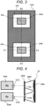
- FIGS. 2 and 3 are structural diagrams of a flat beam generating array antenna used in the radar device 1 according to the second embodiment of the present invention.
- a first radiating unit 110a and a second radiating unit 110b are formed on a first surface S1 of a dielectric substrate 100. Further, a first conductor portion 120a is formed on the first surface S1 of the dielectric substrate 100 and a second conductor portion 130a is formed on a second surface S2 opposite to the first surface S1 of the dielectric substrate 100. Further, a through-hole 400a is formed to electrically connect a conductor of the first surface S1 of the dielectric substrate 100 and a conductor of the second surface S2.
- a first horn 200a of which at least an the inner surface is formed of a conductor is attached to the side of the first surface S1 of the dielectric substrate 100 and a first dielectric lens 300a is disposed in the vicinity of a radiation side opening of each first horn 200a.
- antennas according to embodiments to be described later radiate a radio wave substantially in parallel with a first optical axis D1a-D1a' and a second optical axis D1b-D1b' of the first dielectric lens 300a.
- a first virtual line (longitudinal center line) A1-A1' is a line passing through the center of the radiation side opening of the first horn 200a and having a shortest length
- a second virtual line (horizontal center line) B1 -B1' is a line passing through the center of the first virtual line A1-A1' and orthogonal to the first virtual line A1-A1'.
- one half (that is, a length of one radiation side opening in an A1-A1' direction) of the first virtual line A1-A1' is longer than the second virtual line B1-B1'. That is, in the present embodiment, the radiation side opening of the first horn 200a has a rectangular shape in which a direction (longitudinal direction) of the first virtual line A1-A1' is longer than a direction (transverse direction) of the second virtual line B1-B1'.
- a third virtual line C1-C1' is a line passing through an intersection of the first virtual line A1-A1' and the second optical axis D1b-D1b' and orthogonal to the first virtual line A1-A1'.
- FIG. 2(A) shows a shape of the antenna according to the present embodiment as viewed from the radiation side opening of the first horn 200a. Further, FIG. 2(B) shows a cross-sectional shape along the first virtual line A1-A1' of the antenna. Further, FIG. 2(C) shows a cross-sectional shape of the antenna according to the present embodiment along the third virtual line C1-C1'.
- FIG. 3 shows a shape of the dielectric substrate 100 as viewed from the side of the first surface S1.
- the first conductor portion 120a is formed to surround the first radiating unit 110a and the second radiating unit 110b at a constant distance from the first radiating unit 110a and the second radiating unit 110b.
- the first conductor portion 120a is electrically connected to the second conductor portion 130a formed on the second surface S2 of the dielectric substrate 100 via the through-hole 400a ( FIG. 2 ).
- first conductor portion 120a and the second conductor portion 130a function as reference potential surfaces of the first radiating unit 110a and the second radiating unit 110b, and each of the first radiating unit 110a and the second radiating unit 110b operates as a patch antenna and radiates an electromagnetic wave from the side of the first surface S1 of the dielectric substrate 100.
- a radiation source side opening that is located at the side opposite to a radio wave traveling direction of the radiation side opening of the first horn 200a is disposed on the side of the first surface S1 of the dielectric substrate 100 so as to include one first radiating unit 110a and one second radiating unit 110b. That is, the first horn 200a has two horn shapes that are symmetrical (upper and lower) about the second virtual line B1-B1'.
- the antenna according to the present embodiment is configured to include the first radiating unit 110a, the second radiating unit 110b, and the two first horns 200a.
- An interval at which the through-holes 400a are disposed is preferably shorter than one fourth of a wavelength of the electromagnetic wave used in the dielectric substrate 100.
- the first horn 200a is electrically connected to the first conductor portion 120a, so that a potential of the first horn 200a can become equal to a reference potential of the first radiating unit 110a and the second radiating unit 110b. Therefore, the electromagnetic waves radiated from the first radiating unit 110a and the second radiating unit 110b can be efficiently transmitted to the first horn 200a.
- the first dielectric lenses 300a having convex shapes are formed in continuous convex shapes of the same number as the radiating units 110a and 110b in the direction of the first virtual line A1-A1' .
- the two first dielectric lenses 300a of the antenna are continuously disposed in the direction of the first virtual line A1-A1' and have convex shapes symmetrical (upper and lower) to each other with the second virtual line B1-B1' as an axis. Furthermore, the first radiating unit 110a and the second radiating unit 110b are disposed at positions approximately matched with a focal position of the first dielectric lens 300a. A diameter of the convex portion constituting the first dielectric lens 300a is longer than a dimension in the direction along the third virtual line C1-C1' in the surface of the radiation side opening of the first horn 200a.
- the diameter of the first dielectric lens 300a is reduced to half the diameter in the case where the first dielectric lens 300a has one convex shape.
- the diameter of the dielectric lens and the focal distance are generally in an approximately proportional relation, the focal distance of the first dielectric lens 300a is shortened to approximately half and the first dielectric lens 300a can be miniaturized (reduced in size) in an electromagnetic wave radiation direction (direction of the first optical axis D1a-D1a' or the second optical axis D1b-D1b').
- the first dielectric lens 300a is formed in a shape of a cylinder that is hyperbolic in the direction of the first virtual line A1-A1' and is linear in the direction of the second virtual line B1-B1'. As a result, it is possible to suppress side lobes of the beam radiated from the first dielectric lens 300a in the direction of the first virtual line A1-A1' and the direction of the second virtual line B1-B1'.
- a center 10a ( FIG. 3 ) of the first radiating unit 110a is preferably disposed at an intersection of the first optical axis D1a-D1a' of the first dielectric lens 300a and the first surface S1 of the dielectric substrate 100 and a center 10b of the second radiating unit 110b is preferably disposed at an intersection of the second optical axis D1b-D1b' of the first dielectric lens 300a and the first surface S1 of the dielectric substrate 100.
- a spherical electromagnetic wave radiated from the first radiating unit 110a propagates through the first horn 200a, is input to the first dielectric lens 300a, propagates through the first dielectric lens 300a, and is radiated to a space. During the propagation, the spherical wave is converted into a plane wave by the first horn 200a and the first dielectric lens 300a. Similarly, the spherical electromagnetic wave radiated from the second radiating unit 110b propagates through the first horn 200a. During the propagation, the spherical wave is converted into a plane wave by the first horn 200a and the first dielectric lens 300a.
- a planar electromagnetic wave originating from the first radiating unit 110a and radiated from the first horn 200a and a planar electromagnetic wave originating from the second radiating unit 110b and radiated from the first horn 200a are synthesized in a space outside the radiation side opening of the first horn 200a and are radiated as a planar electromagnetic wave.
- the antenna according to the present embodiment can radiate a directional beam in a desired direction.
- the antenna according to the present embodiment has a structure in which two horns are connected in the longitudinal direction and one half of the first virtual line A1-A1' (length of the radiation side opening of one horn in the direction of the first virtual line A1-A1') is longer than the second virtual line B1-B1'. That is, in one dielectric lens 300a (a portion of the dielectric lens corresponding to one radiating unit) provided on the radiation side of the antenna, the length in the direction of the first virtual line A1-A1' is longer than the length in the direction of the second virtual line B1-B1').
- the first virtual line A1-A1' is disposed in the longitudinal direction (vertical direction) and the second virtual line B1-B1' is disposed in the transverse direction (horizontal direction, specifically, the vehicle width direction).
- a flat beam is generated in which a width in the direction (transverse direction) of the second virtual line B1-B1' is larger than a width in the direction (longitudinal direction) of the first virtual line A1-A1'.
- An electric field surface direction (E surface direction) of the electromagnetic waves radiated from the first radiating unit 110a and the second radiating unit 110b is parallel to the first virtual line A1-A1', so that the shape of the beam radiated from the first horn 200a is likely to be narrowed in the direction of the first virtual line A1-A1', which is preferable.
- FIG. 4 is a block diagram of the receiving side of the radar device 1 having the flat beam generating array antenna shown in FIG. 2 .
- An example of the receiving side of the radar device 1 having the flat beam generating array antenna will be described below.
- the radar device 1 shown in FIG. 4 has a flat beam generating array antenna 10, a first receiving circuit 520a, and a second receiving circuit 520b.
- the first receiving circuit 520a has a first input terminal 521a to which the third radiating unit 110c is connected and the second receiving circuit 520b has a second input terminal 521b to which the fourth radiating unit 110d is connected.
- the electromagnetic wave input to the first dielectric lens 300a is converted into an electrical signal in the third radiating unit 110c via the first dielectric lens 300a and is input to the first input terminal 521a of the first receiving circuit 520a.
- the electromagnetic wave input to the first dielectric lens 300a is converted into an electrical signal in the fourth radiating unit 110d via the first dielectric lens 300a and is input to the second input terminal 521b of the second receiving circuit 520b.
- the receiving antenna of the radar device 1 having the flat beam generating array antenna according to the present embodiment is applicable to the radar device 1 that measures a distance to an obstacle or the like and a relative speed of the obstacle or the like. Furthermore, since the flat beam generating array antenna according to the embodiment of the present invention generates a flat beam of which beam width in the longitudinal direction is wider than the beam width in the lateral direction as described above, it is applicable to the radar device 1 that measures a vertical position (angle from a horizontal surface) of the obstacle or the like in the vertical direction (the direction of the first virtual line A1-A1' (not shown in FIG. 4 )).
- each of the receiving antennas 108 has one radiating unit (patch antenna) that radiates the electromagnetic wave, one horn antenna that surrounds the radiating unit, and one dielectric lens that is disposed in an opening end of the horn antenna and converts the electromagnetic wave into a plane wave.
- FIG. 5 is a block diagram of the radar device 1 having the flat beam generating array antenna shown in FIG. 2 .
- the radar device 1 having the signal processing unit 103 will be described.
- the signal processing unit 103 is connected to a first transmitting circuit 510a, a first receiving circuit 520a, a second receiving circuit 520b, a third receiving circuit 520c, and a fourth receiving circuit 520d.
- the signal processing unit 103 supplies a signal to be transmitted from the antenna to the first transmitting circuit 510a and processes signals output from the first receiving circuit 520a, the second receiving circuit 520b, the third receiving circuit 520c, and the fourth receiving circuit 520d.
- a first transmitted signal Tsg1 output from the signal processing unit 103 and input to the first transmitting circuit 510a is output as a second transmitted signal Tsg2 from a first terminal 511a of the first transmitting circuit 510a. Further, the first transmitted signal Tsg1 is input to the first radiating unit 110a and is radiated as a transmitted electromagnetic wave from the first dielectric lens 300a. Similarly, a second transmitted signal Tsg2 output from a second terminal 512a of the first transmitting circuit 510a is input to the second radiating unit 110b and is radiated as a transmitted electromagnetic wave from the first dielectric lens 300a.
- the transmitted electromagnetic wave radiated from the first dielectric lens 300a is reflected by the obstacle or the like.
- the reflected electromagnetic wave is converted into a first received signal Rsg1 in the third radiating unit 110c via the second dielectric lens 300b and is further input to the first input terminal 521a of the first receiving circuit 520a.
- the first received signal Rsg1 is output as a fifth received signal Rsg5 from the first receiving circuit 520a and is input to the signal processing unit 103.
- the reflected electromagnetic wave is converted into a second received signal Rsg2 in the fourth radiating unit 110d via the second dielectric lens 300b and is further input to the second input terminal 521b of the second receiving circuit 520b.
- the second received signal Rsg2 is output as a sixth received signal Rsg6 from the second receiving circuit 520b and is input to the signal processing unit 103.
- the reflected electromagnetic wave is converted into a third received signal Rsg3 in the fifth radiating unit 110e via the third dielectric lens 300c and is further input to the third input terminal 521c of the third receiving circuit 520c.
- the third received signal Rsg3 is output as a seventh received signal Rsg7 from the third receiving circuit 520c and is input to the signal processing unit 103.
- the reflected electromagnetic wave is converted into a fourth received signal Rsg4 in the sixth radiating unit 110f via the third dielectric lens 300c and is further input to the fourth input terminal 521d of the fourth receiving circuit 520d.
- the fourth received signal Rsg4 is output as an eighth received signal Rsg8 from the fourth receiving circuit 520d and is input to the signal processing unit 103.
- the signal processing unit 103 synthesizes and processes the signals output from the first receiving circuit 520a, the second receiving circuit 520b, the third receiving circuit 520c, and the fourth receiving circuit 520d. That is, the radar device 1 according to the present embodiment has one transmitting channel and four receiving channels and processes signals corresponding to the four receiving channels.
- the transmitting/receiving antenna of the radar device 1 having the flat beam generating array antenna according to the present embodiment can measure a vertical position (angle from a horizontal surface) of an obstacle or the like in the vertical direction (the direction of the first virtual line A1-A1') and a horizontal position (angle from a frontal direction) of an obstacle or the like in the horizontal direction (the direction of the third virtual line C1-C1'). The details will be described later using to FIGS. 6 to 8 .
- FIG. 6 is diagram showing the radar device 1 having four receiving channels in which receiving antennas of two elements are disposed in the horizontal direction and receiving antennas of two elements are disposed in the vertical direction, as viewed from the top surface (front) of the antenna.
- An interval of the receiving antennas in each configuration direction of each receiving antenna 108 (108a to 108d) is constant.
- X1 (X1a, X1a', X1b, and X1b') and Y1 (Y1a, Y1a', Y1b, and Y1b') of each receiving antenna are centers of the receiving antenna in the vertical direction (height) and the horizontal direction (width), respectively.
- X1a-X1a' and X1b-X1b' are parallel and Y1a-Y1a' and Y1b-Y1b' are parallel.
- X1-X1' (X1a-X1a' and X1b-X1b') and Y1-Y1' (Y1a-Y1a' and Y1b-Y1b') are orthogonal and an intersection thereof becomes a center portion 109 (109a to 109d) of each receiving antenna.
- the shape of the receiving antenna 108 is not limited to this, the center portions 109 of the receiving antennas arrayed in the same direction may be constituted on a straight line.
- the plurality of receiving antennas 108 are arrayed in the horizontal direction (first direction) and the vertical direction (second direction) crossing the horizontal direction.
- the horizontal direction (first direction) and the vertical direction (second direction) cross perpendicularly.
- the receiving channels to which the receiving antennas 108a to 108d have been connected are respectively described as receiving channels 1 to 4.
- Range is a relative distance of the target object and Rate is a relative speed of the target object. Range and Rate are calculated in each receiving channel and are extracted by the number of receiving channels used. Therefore, values of Range and Rate are used by averaging the values extracted from each receiving channel.
- XRNG XRNG1 and XRNG2
- the horizontal angle is calculated from a reception phase difference of the electromagnetic waves input to the receiving antennas arrayed in the horizontal direction.
- Height (Height1 and Height2) is a vertical direction distance of the target object and is calculated from a vertical direction detection angle (hereinafter, referred to as a vertical angle) and Range.
- the vertical angle is calculated from a reception phase difference of the electromagnetic waves input to the receiving antennas arrayed in the vertical direction.
- a combination of a receiving channel 1 (ch1) and a receiving channel 2 (ch2) and a combination of a receiving channel 3 (ch3) and a receiving channel 4 (ch4) receive a reflected wave, so that it is possible to extract two horizontal angles of the target object.
- Horizontal direction distances calculated from the horizontal angles extracted from the combination of the receiving channel 1 (ch1) and the receiving channel 2 (ch2) and the combination of the receiving channel 3 (ch3) and the receiving channel 4 (ch4) are respectively XRNG1 and XRNG2.
- a combination of a receiving channel 1 (ch1) and a receiving channel 4 (ch4) and a combination of a receiving channel 2 (ch2) and a receiving channel 3 (ch3) receive a reflected wave, so that it is possible to extract two vertical angles of the target object, and vertical direction distances calculated therefrom are respectively Height1 and Height2.
- the radar device 1 cyclically repeats an operation of transmitting and receiving the electromagnetic wave and calculating a detection result of the target object.
- one processing cycle is called a frame.
- the accuracy of the two detection angles extracted by the radar device 1 in each frame increases or decreases due to an influence of reflection, but the accuracy is equivalent on average. Therefore, as a comparative example, there is an advantage of being less affected by a reflection environment as compared with a radar device in which receiving antennas of three elements are disposed in an L shape and the receiving antennas are arrayed in the horizontal direction and the vertical direction.
- FIG. 7 shows that performance and load are in a trade-off relation according to the number of channels used, in a radar device according to a second embodiment of the present invention.
- Fr in the drawing means a frame.
- the radar performance and the processing load when the information is extracted using all the receiving channels correspond to an item of the number of channels used 4 in FIG. 7 .
- FIG. 7 shows that, in the receiving antenna of FIG. 6 , for example, when the number of channels used is 3, three distances (relative distances) per frame, three speeds (relative speeds) per frame, one horizontal detection angle (horizontal angle) per frame, and one vertical detection angle (vertical angle) per frame can be detected.
- FIG. 8A shows a method of selecting the receiving channels to be used from all the receiving channels and regularly changing a combination thereof for each frame, in the receiving antenna configuration of FIG. 6 and in an embodiment of the present invention .
- receiving channels to which white receiving antennas have been connected are receiving channels that are not used in frames Fr1 to Fr4.
- FIG. 8B is a diagram showing that combinations of the receiving channels of the respective frames are regularly changed from the frame Fr1 to the frame Fr4 and this is repeated cyclically.
- a horizontal angle is extracted from the receiving channel 1 (ch1) and the receiving channel 2 (ch2)
- a vertical angle is extracted from the receiving channel 2 (ch2) and the receiving channel 3 (ch3).
- the receiving channels for extracting the horizontal angles are different between the frames Fr1 and Fr4 and the frames Fr2 and Fr3
- the receiving channels for extracting the vertical angles are different between the frames Fr1 and Fr2 and the frames Fr3 and Fr4.
- the radar performance and the load at this time conform to an item of the number of channels used 3 in FIG. 7 .
- the signal processing unit 103 processes a second signal Sig2 corresponding to a combination (108a, 108b, and 108c) of receiving antennas including the two receiving antennas (108a and 108b) arrayed in the horizontal direction (first direction), and in a next frame Fr2 (second frame) of the frame Fr1, the signal processing unit 103 processes a second signal Sig2 corresponding to a combination (108b, 108c, and 108d) of receiving antennas including the two receiving antennas (108b and 108c) arrayed in the vertical direction (second direction).
- the signal processing unit 103 processes a second signal Sig2 corresponding to a first combination (108a, 108b, and 108c) of three receiving antennas and calculates a first angle of the target object (object) with respect to the horizontal direction (first direction) and a second angle of the target object with respect to the vertical direction (second direction).
- the signal processing unit 103 processes a second signal Sig2 corresponding to a second combination (108b, 108c, and 108d) of three receiving antennas and calculates a third angle of the target object with respect to the horizontal direction and a fourth angle of the target object with respect to the vertical direction.
- the second angle and the fourth angle are the same.
- the relative distance Range for example, the average value of the three relative distances
- the relative speed Rate for example, the average value of the three relative speeds
- one horizontal angle for example, the relative angles
- one vertical angle for example, the relative angle
- the information amount of the detection angle for each frame is reduced.
- the combinations of the frames Fr1 to Fr4 the same result as the case of using the four receiving channels is extracted. That is, it can be said that the radar performance of the four receiving channels is calculated (achieved) by time division. In order to timedivide the radar performance of the four channels, combinations of the channels not to be used are determined so that there is no bias.
- the data amount becomes 3/4 and the processing load is also reduced as compared with the case where the four receiving channels are used. Therefore, a time per frame can be shortened.
- the receiving channels to be used and the combinations thereof are appropriately selected from the receiving channels constituting the radar device and the combinations are regularly changed.
- the receiving channels to be used and the combinations thereof are appropriately selected from the receiving channels constituting the radar device and the combinations are regularly changed.
- FIG. 9 is an example of a flow of processing for ensuring functional safety. As shown in FIG. 9 , processing for determining a failure of the receiving channel may be included.
- the signal processing unit 103 regularly switches the combination of the receiving channels (receiving elements) (S10).
- the signal processing unit 103 calculates Range, Rate, XRNG1 and 2, and Hight1 and 2 (detection results) (S15).
- the signal processing unit 103 determines whether there is information not normally calculated, from a comparison between information (detection result) calculated in a certain frame and information calculated in a previous frame (S20). When there is the information not calculated normally, the signal processing unit 103 detects (determines) a failure of the receiving channel (S25).
- the signal processing unit 103 turns on a failure flag indicating the failure of the receiving channel (S30).
- the signal processing unit 103 repeats processing for calculating the detection result in the receiving channel (normal channel) in which the failure is not detected (S35). Further, the signal processing unit 103 outputs the detection result calculated in the normal channel to the user interface 105 (vehicle navigation system or the like) (S40).
- the information of Height1 of the frame Fr2 is not correctly extracted. It is determined whether or not the extracted information is correct by comparing the frame Fr1 and Height1 of the frame Fr2 and the failure determination is performed. Thereby, functional safety can be ensured.
- the signal processing unit 103 compares the processing result in the first frame (for example, the frame Fr1) with the processing result in the second frame (for example, the frame Fr2), thereby performing the failure determination of the receiving channel (for example, ch2) indicating the path from each receiving antenna 108 (for example, 108b) to the signal processing unit 103. Thereby, reliability of the radar device 1 can be improved.
- After the failure determination information is extracted using the normal receiving channel without using the failed receiving channel.
- the signal processing unit 103 generates, from the second signal Sig2 corresponding to the non-failed receiving channel 108, a combination of the second signal Sig2 to be processed for each frame. Thereby, detection of the position of the object can be continuously performed.
- FIG. 10 in a receiving antenna configuration of FIG. 6 , two receiving channels are selected and a combination of channels to be received for each frame is regularly changed from Fr1 to Fr4, which is repeated.
- a receiving channel 1 (ch1) and a receiving channel 2 (ch2) are used and only a relative distance, a relative speed, and a horizontal angle are extracted.
- a receiving channel 2 (ch2) and a receiving channel 3 (ch3) are used and only a relative distance, a relative speed, and a vertical angle are extracted. Radar performance and load at this time correspond to an item of the number of channels used 2 in FIG. 7 .
- a plurality of receiving antennas 108 are four and are arrayed in 2 rows and 2 columns.
- a signal processing unit 103 processes a second signal Sig2 corresponding to a combination (108a and 108b) of two receiving antennas arrayed in a horizontal direction (first direction) and calculates an angle of a target object (object) with respect to the horizontal direction, in the frame Fr1 (first frame). Further, the signal processing unit 103 processes a second signal Sig2 corresponding to a combination (108b and 108c) of two receiving antennas arrayed in a vertical direction (second direction) and calculates an angle of the target object with respect to the vertical direction, in the frame Fr2 (second frame).
- the relative distance Range and the relative speed Rate are extracted for one target object in each frame.
- one horizontal angle and one vertical angle are alternately extracted for each frame. That is, since the horizontal angle and the vertical angle are extracted every other frame, position accuracy of the target object decreases.
- detection angles of two directions can be extracted in the received signals of the two receiving channels.
- the combinations of the receiving channels from the frame Fr1 to the frame Fr4 it becomes equal to information extracted in the case of using four receiving channels. That is, it is synonymous with lengthening a cycle of the above time division.
- the follow-up processing is processing for determining whether the target object detected in each frame is the same target object. For example, when a target object A detected in a frame has a relative distance of 100 m and a relative speed of 0 m/s, a target object B detected in a next frame has a relative distance of 100 m and a relative speed of 0 m/s, and a target object C has a relative distance of 150 m and a relative speed of 10m/s, it can be estimated that the target object A and the target object B are the same. It is possible to complement information not calculated by linking with the information of the target object detected in the past by such a method. For example, it is assumed that the information not calculated is the same as the result of the past frame.
- a method of selecting receiving channels and regularly changing a combination thereof is also applicable to a receiving antenna configuration of M ⁇ N receiving channels including M and N (M and N > 2) receiving antennas respectively arrayed in horizontal and vertical directions.
- M and N M and N > 2
- a plurality of receiving antennas 108 (108a to 108f) are arrayed in M rows and N columns (M and N: natural number of 2 or more).
- FIG. 11 is diagram showing a radar device 1 having six receiving channels in which receiving antennas of three elements are disposed in a horizontal direction and receiving antennas of two elements are disposed in a vertical direction, as viewed from a top surface of the antenna.
- X2a-X2a' and X2b-X2b' are parallel and Y2a-Y2a', Y2b-Y2b', and Y2c-Y2c' are parallel.
- X2-X2' (X2a-X2a' and X2b-X2b') and Y2-Y2' (Y2a-Y2a', Y2bY2b', and Y2c-Y2c') are orthogonal.
- the receiving antenna configuration in the present embodiment is not limited to this and center portions 109 (109a to 109f) of the antennas arrayed in the same direction are arrayed linearly.
- the receiving channels to which the receiving antennas 108a to 108f have been connected are respectively described as receiving channels 1 to 6.
- three vertical angles are extracted from combinations of the receiving channels in which the receiving channel 1 (ch1) and the receiving channel 4 (ch4), the receiving channel 2 (ch2) and the receiving channel 5 (ch5), and the receiving channel 3 (ch3) and the receiving channel 6 (ch6) have been connected, and Height1, Height2, and Height3 are calculated.
- horizontal angles may be extracted from the receiving channel 1 (ch1) and the receiving channel 3 (ch3) and the receiving channel 4 (ch4) and the receiving channel 6 (ch6).
- FIG. 12 in the radar device 1 having the receiving antenna configuration of FIG. 11 as an example of the present embodiment, similar to the second embodiment, two receiving channels are selected in each of the frames Fr1 to Fr7 and a combination thereof is regularly changed from Fr1 to Fr7, which is repeated.
- the combination of receiving channels to be used is determined, as long as there is no reason such as a failure of the receiving channel, a bias is prevented from occurring in the channels not to be used, similar to the above embodiment.
- the two channels are selected as shown in FIG. 12 , for example, like the receiving channel 1 (ch1) and receiving channel 2 (ch2) in the frame Fr1 and the receiving channel 1 (ch1) and the receiving channel 4 (ch4) in the frame Fr2, the horizontal angle and the vertical angle are alternately extracted for each frame and the receiving channels to be used are determined. This is to avoid missing of information of the target object over a long time.
- a signal processing unit 103 processes a second signal Sig2 corresponding to a combination of receiving antennas including the two receiving antennas (for example, 108a and 108b) arrayed in any row of M rows, in the frame Fr1 (first frame).
- the signal processing unit 103 processes a second signal Sig2 corresponding to a combination of receiving antennas including the two receiving antennas (for example, 108a and 108d) arrayed in any column of N columns, in the frame Fr2 (second frame).
- positions of the target object (object) in the two directions can be alternately detected.
- only the same direction may be calculated over several frames. This determination may be made from map information, for example. Specifically, this corresponds to the case where it is flat and the height of the target object does not need to be measured.
- the receiving channels need to be combined so that the detection angles in the two directions can be calculated. That is, in a combination of the receiving channel 1 (ch1), the receiving channel 2 (ch2), and the receiving channel 3 (ch3) and a combination of the receiving channel 4 (ch4), the receiving channel 5 (ch5), and the receiving channel 6 (ch6), since the vertical angle is extracted, these combinations are excluded. This is to prevent missing of information of the target object.
- the number of receiving channels to be used can be determined according to the environment, for example. Optimal radar performance and load according to a scene can be achieved by judgment criteria such as a traffic variation, a distance to the target object, and a high or low travelling speed. For example, in an environment where traffic is low and the target object is far away, high radar performance is not required. Therefore, by setting the number of receiving channels used to two, the radar performance may be decreased and the processing load may be decreased. The same is applicable to the third embodiment and the fourth embodiment.
- the signal processing unit 103 changes the number of receiving channels to be blocked, according to the surrounding environment of the radar device 1.
- the method of calculating the detection angle is described on the premise of a mono-pulse system, other calculation methods may be used.
- a calculation method such as a MUSIC method may be used.
- FIGS. 13A to 13C show an example of a receiving antenna configuration (arrangement) of a radar device 1 according to a modification of an embodiment , which is not an embodiment of the present invention but an example useful for its understanding .
- the contents described in each embodiment can also be implemented in a configuration in which a row of receiving antennas is shifted in the horizontal direction or the vertical direction as shown in FIG. 13A , a configuration in which the receiving antennas of the horizontal direction and the vertical direction are alternately arrayed as shown in FIG. 13B , and a receiving antenna configuration in which a first direction where the receiving antennas are arrayed and a second direction of the receiving antennas crossing the first direction do not cross perpendicularly.
- angle information is not necessarily calculated in the horizontal direction and the vertical direction with respect to the ground. However, from the calculated angle information of the two directions, the angle information can be recalculated in the horizontal direction and the vertical direction with respect to the ground.
- a method of selecting receiving channels and regularly changing a combination thereof is also applicable to a receiving antenna configuration in which a plurality of receiving antennas are configured in a single direction. At this time, the same as the above embodiments is omitted.
- FIG. 14 is diagram showing a radar device 1 having four receiving channels in which receiving antennas of four elements are disposed in a horizontal direction, as viewed from a top surface (front) of the antenna.
- the receiving channels to which receiving antennas 108a to 108d have been connected are respectively described as a receiving channel 1 (ch1) to a receiving channel 4 (ch4).
- the receiving channels in which a combination of the receiving channel 1 (ch1) and the receiving channel 2 (ch2), a combination of the receiving channel 2 (ch2) and the receiving channel 3 (ch3), and a combination of the receiving channel 3 (ch3) and the receiving channel 4 (ch4) have been connected receive a reflected wave, so that it is possible to extract three horizontal angles of a target object.
- Horizontal direction distances calculated from the horizontal angles extracted from the combination of the receiving channel 1 (ch1) and the receiving channel 2 (ch2), the combination of the receiving channel 2 (ch2) and the receiving channel 3 (ch3), and the combination of the receiving channel 3 (ch3) and the receiving channel 4 (ch4) are respectively XRNG1, XRNG2, and XRNG3.
- the receiving antenna configuration according to the present embodiment is not limited to this and is applicable even when a plurality of receiving antennas are configured in the vertical direction.
- FIG. 15 in the radar device 1 having the receiving antenna configuration in the horizontal direction of FIG. 14 as an example of the present embodiment, similar to the embodiment, two receiving channels are selected in each frame and a combination thereof is regularly changed from the frame Fr1 to the frame Fr3, which is repeated.
- the receiving channels used to extract the horizontal angle in each frame are different and an amount of data acquired by combining the receiving channels for one cycle becomes equivalent to an amount of data acquired by using all the channels.
- the number of divisions of target objects existing at the same distance and speed can be reduced. Therefore, similar to the above embodiments, it is desirable to select the number of channels used, according to the environment, for example, a road situation.
- FIG. 16 is a diagram showing an example in which information calculated by the radar device 1 according to each of the first to fifth embodiments of the present invention is output to the user interface 105.
- the signal processing unit 103 may input information of preceding vehicles or upper target objects (signs, drones, or the like) extracted by switching the receiving channels for each frame to the user interface 105 and may display the information on the user interface 105 (for example, a vehicle navigation system, a head-up display (HUD), or the like).
- the information may be input to the vehicle control unit 106 (vehicle control CPU) or an in-vehicle camera to support vehicle control or travelling control.
- the individual configurations and functions may be designed by integrated circuits and may be realized by hardware. Further, the individual configurations and functions may be realized by software by analyzing programs for realizing the functions by a processor (microcomputer or the like) and executing the programs by the processor. Information such as the programs, the tables, and the files for realizing the individual functions may be stored in a recording device such as a memory, a hard disk, and a solid state drive (SSD) or a recording medium such as an IC card, an SD card, and a DVD.
- a recording device such as a memory, a hard disk, and a solid state drive (SSD) or a recording medium such as an IC card, an SD card, and a DVD.
- SSD solid state drive
Landscapes
- Engineering & Computer Science (AREA)
- Radar, Positioning & Navigation (AREA)
- Remote Sensing (AREA)
- Physics & Mathematics (AREA)
- General Physics & Mathematics (AREA)
- Computer Networks & Wireless Communication (AREA)
- Electromagnetism (AREA)
- Computer Security & Cryptography (AREA)
- Radar Systems Or Details Thereof (AREA)
- Variable-Direction Aerials And Aerial Arrays (AREA)
- Aerials With Secondary Devices (AREA)
Claims (4)
- Radarvorrichtung, umfassend:eine Übertragungsantenne, die dazu ausgelegt ist, eine elektromagnetische Welle zu übertragen;vier Empfangsantennen (108a-d), die dazu ausgelegt sind, eine reflektierte Welle von einem Objekt, das die elektromagnetische Welle reflektiert, zu empfangen und die reflektierte Welle in ein erstes Signal (Sig1) umzuwandeln;vier Empfangsschaltungen (520), die jeweils mit den Empfangsantennen verbunden und dazu ausgelegt sind, aus dem ersten Signal ein zweites Signal (Sig2) zu erzeugen; undeine Signalverarbeitungseinheit (103), die dazu ausgelegt ist, das zweite Signal zu verarbeiten,wobeidie mehreren Empfangsantennen in zwei Reihen und zwei Spalten in einer ersten Richtung und einer zweiten Richtung, die die erste Richtung senkrecht kreuzt, angeordnet sind, unddie Signalverarbeitungseinheit dazu ausgelegt ist,eine Kombination des zu verarbeitenden zweiten Signals für jeden Frame, der eine Zeitspanne angibt, die von dem Zeitpunkt, zu dem die Übertragungsantenne die elektromagnetische Welle überträgt, bis zu dem Zeitpunkt, zu dem die Signalverarbeitungseinheit das zweite Signal verarbeitet, zu schalten,das zweite Signal zu verarbeiten, das einer ersten Kombination von drei Empfangsantennen entspricht, die in einer ersten Reihe der beiden Reihen in der ersten Richtung und einer zweiten Spalte der beiden Spalten in der zweiten Richtung angeordnet sind, und die Winkel des Objekts in Bezug auf die jeweiligen ersten und zweiten Richtungen in einem ersten Frame zu berechnen,das zweite Signal zu verarbeiten, das einer zweiten Kombination von drei Empfangsantennen entspricht, die in einer zweiten Reihe der beiden Reihen in der ersten Richtung und der zweiten Spalte angeordnet sind, und die Winkel des Objekts in Bezug auf die jeweiligen ersten und zweiten Richtungen in einem zweiten Frame, der auf den ersten Frame folgt, zu berechnen,das zweite Signal zu verarbeiten, das einer dritten Kombination von drei Empfangsantennen entspricht, die in der zweiten Reihe und einer ersten Spalte der beiden Spalten in der zweiten Richtung angeordnet sind, und die Winkel des Objekts in Bezug auf die jeweiligen ersten und zweiten Richtungen in einem dritten Frame, der auf den zweiten Frame folgt, zu berechnen, unddas zweite Signal zu verarbeiten, das einer vierten Kombination von drei Empfangsantennen entspricht, die in der ersten Reihe und der ersten Spalte angeordnet sind, und die Winkel des Objekts in Bezug auf die jeweiligen ersten und zweiten Richtungen in einem vierten Frame, der auf den dritten Frame folgt, zu berechnen, undwobei die Signalverarbeitungseinheit dazu ausgelegt ist, die Verarbeitung für die ersten bis vierten Frames und die Berechnung der Winkel zu wiederholen, während sie zyklisch die vier verschiedenen ersten bis vierten Kombinationen der drei Empfangsantennen, die in den ersten bis vierten Frames zu verwenden sind, aus den vier Empfangsantennen ändert.
- Radarvorrichtung nach Anspruch 1, wobei
die Signalverarbeitungseinheit (103) dazu ausgelegt ist, ein Verarbeitungsergebnis in einem der ersten bis vierten Rahmen und ein Verarbeitungsergebnis im darauf folgenden Rahmen zu vergleichen und eine Fehlerbestimmung von Empfangskanälen, die Pfade von den jeweiligen Empfangsantennen (108a-d) zur Signalverarbeitungseinheit angeben, durchzuführen. - Radarvorrichtung nach Anspruch 2, wobei
die Signalverarbeitungseinheit (103) dazu ausgelegt ist, eine Kombination des zweiten Signals (Sig2), das für jeden Rahmen zu verarbeiten ist, aus dem zweiten Signal zu erzeugen, das dem Empfangskanal entspricht, der nicht ausfällt. - Radarvorrichtung nach Anspruch 1, wobei
jede der Empfangsantennen (108a-d) aufweist:eine Patch-Antenne (110a-b), die dazu ausgelegt ist, die elektromagnetischen Welle auszustrahlen,eine Hornantenne (201), die die Patch-Antenne umgibt, undeine dielektrische Linse (301), die in einem Öffnungsende der Hornantenne angeordnet ist und dazu ausgelegt ist, die elektromagnetische Welle in eine ebene Welle umzuwandeln.
Applications Claiming Priority (2)
| Application Number | Priority Date | Filing Date | Title |
|---|---|---|---|
| JP2016234073 | 2016-12-01 | ||
| PCT/JP2017/041429 WO2018101082A1 (ja) | 2016-12-01 | 2017-11-17 | レーダ装置 |
Publications (3)
| Publication Number | Publication Date |
|---|---|
| EP3550323A1 EP3550323A1 (de) | 2019-10-09 |
| EP3550323A4 EP3550323A4 (de) | 2020-11-04 |
| EP3550323B1 true EP3550323B1 (de) | 2025-06-04 |
Family
ID=62241421
Family Applications (1)
| Application Number | Title | Priority Date | Filing Date |
|---|---|---|---|
| EP17876393.4A Active EP3550323B1 (de) | 2016-12-01 | 2017-11-17 | Radarvorrichtung |
Country Status (4)
| Country | Link |
|---|---|
| US (1) | US11300654B2 (de) |
| EP (1) | EP3550323B1 (de) |
| JP (1) | JP6846437B2 (de) |
| WO (1) | WO2018101082A1 (de) |
Families Citing this family (9)
| Publication number | Priority date | Publication date | Assignee | Title |
|---|---|---|---|---|
| DE112019005233T5 (de) * | 2018-11-27 | 2021-07-15 | Hitachi Astemo, Ltd. | Radarvorrichtung |
| JP7289070B2 (ja) * | 2019-03-11 | 2023-06-09 | パナソニックIpマネジメント株式会社 | レーダー装置および車両 |
| US11543511B2 (en) * | 2019-03-11 | 2023-01-03 | Panasonic Intellectual Property Management Co., Ltd. | Radar apparatus and vehicle |
| CN112698299B (zh) * | 2019-10-22 | 2024-08-30 | 广州极飞科技股份有限公司 | 一种雷达天线、雷达、无人机和设备 |
| CN114651189A (zh) * | 2019-11-25 | 2022-06-21 | 三菱电机株式会社 | 物体检测装置 |
| FR3116910B1 (fr) * | 2020-12-01 | 2022-12-16 | Valeo Vision | Ensemble de véhicule comprenant un capteur radar et une lentille à gradient d’indice |
| CN113013596B (zh) * | 2021-02-26 | 2023-08-29 | Oppo广东移动通信有限公司 | 天线装置、壳体及电子设备 |
| CN116130964B (zh) * | 2023-02-08 | 2025-09-16 | 东南大学 | 一种结构紧凑的可重构透射阵波束扫描天线 |
| CN117728177B (zh) * | 2023-12-10 | 2025-08-22 | 西安电子工程研究所 | 用于连续波雷达两维干涉测角的阵列天线 |
Family Cites Families (37)
| Publication number | Priority date | Publication date | Assignee | Title |
|---|---|---|---|---|
| US3274590A (en) * | 1950-02-06 | 1966-09-20 | Robert M Page | Angle tracking storage radar system |
| DE1248754B (de) * | 1965-05-08 | 1967-08-31 | Telefunken Patentverw ertungsgesellschaft mbH, Ulm/Donau | Verfahren zur Bestimmung der Emfallsnchtung von N (N > 1) in einem Kanal liegenden ms besondere kohärenten elektromagnet! sehen Wellen |
| US4357608A (en) * | 1980-09-03 | 1982-11-02 | The United States Of America As Represented By The Secretary Of The Navy | Scanning radar system |
| US4740045A (en) * | 1986-07-02 | 1988-04-26 | Goodson & Associates, Inc. | Multiple parameter doppler radar |
| US5189426A (en) * | 1991-05-06 | 1993-02-23 | Ivhs Technologies, Inc. | Doppler frequency spectrum de-emphasis for automotive collision avoidance radar system |
| US5510794A (en) * | 1989-07-07 | 1996-04-23 | Asbury; Jimmie R. | Vehicular radar wayside transponder system |
| US6151310A (en) * | 1994-03-24 | 2000-11-21 | Ericsson Inc. | Dividable transmit antenna array for a cellular base station and associated method |
| JPH09288178A (ja) | 1996-04-23 | 1997-11-04 | Toyota Motor Corp | 車載モノパルスレーダ装置 |
| US5933109A (en) * | 1996-05-02 | 1999-08-03 | Honda Giken Kabushiki Kaisha | Multibeam radar system |
| JP3602258B2 (ja) | 1996-05-02 | 2004-12-15 | 本田技研工業株式会社 | マルチビーム・レーダアンテナ |
| JP3433417B2 (ja) * | 1998-04-02 | 2003-08-04 | トヨタ自動車株式会社 | レーダ装置 |
| US6087974A (en) * | 1998-08-03 | 2000-07-11 | Lockheed Martin Corporation | Monopulse system for target location |
| JP4028178B2 (ja) | 2001-02-09 | 2007-12-26 | 株式会社東芝 | 移動体用アンテナ装置 |
| GB2387053B (en) * | 2001-11-12 | 2006-02-01 | Telstra Corp Ltd | Surface wave radar |
| US7626536B1 (en) * | 2004-04-28 | 2009-12-01 | Mark Resources, Inc. | Non-scanning radar for detecting and tracking targets |
| WO2007026792A1 (ja) * | 2005-09-01 | 2007-03-08 | Murata Manufacturing Co., Ltd. | レーダ装置 |
| US7460951B2 (en) * | 2005-09-26 | 2008-12-02 | Gm Global Technology Operations, Inc. | System and method of target tracking using sensor fusion |
| JP4899464B2 (ja) | 2005-12-19 | 2012-03-21 | 株式会社日立製作所 | 無線タグ通信装置及びその通信方法 |
| ES2585590T3 (es) * | 2006-01-17 | 2016-10-06 | Teledyne Australia Pty Ltd. | Aparato de vigilancia y método |
| JP4431157B2 (ja) * | 2007-05-23 | 2010-03-10 | 三菱電機株式会社 | レーダ装置 |
| EP2191292B8 (de) * | 2007-09-19 | 2019-07-31 | Teledyne Australia Pty Ltd | Abbildungssystem und -verfahren |
| DE102008038365A1 (de) * | 2008-07-02 | 2010-01-07 | Adc Automotive Distance Control Systems Gmbh | Fahrzeug-Radarsystem und Verfahren zur Bestimmung einer Position zumindest eines Objekts relativ zu einem Fahrzeug |
| EP2391906B1 (de) * | 2009-01-30 | 2016-12-07 | Teledyne Australia Pty Ltd. | Vorrichtung und verfahren zur unterstützung vertikal gestarteter fahrzeuge |
| JP5418770B2 (ja) * | 2009-07-29 | 2014-02-19 | トヨタ自動車株式会社 | レーダ装置 |
| DE112010005193B4 (de) * | 2010-01-28 | 2022-07-14 | Toyota Jidosha Kabushiki Kaisha | Hindernis-Erfassungsvorrichtung |
| JP5610983B2 (ja) * | 2010-11-01 | 2014-10-22 | 三菱電機株式会社 | レーダ装置 |
| US8928542B2 (en) * | 2011-08-17 | 2015-01-06 | CBF Networks, Inc. | Backhaul radio with an aperture-fed antenna assembly |
| EP2605036B1 (de) * | 2011-12-16 | 2019-10-23 | Trackman A/S | Verfahren und Sensor zur Bestimmung einer Auftreffrichtung einer auftreffenden Strahlung |
| US9835712B2 (en) * | 2012-12-21 | 2017-12-05 | Autoliv Development Ab | Vehicle radar diagnostic arrangement |
| JP6036529B2 (ja) * | 2013-05-08 | 2016-11-30 | 株式会社デンソー | レーダ装置 |
| KR101907173B1 (ko) * | 2013-12-09 | 2018-10-11 | 주식회사 만도 | 차량용 레이더 시스템 및 그의 방위각 추출 방법 |
| DE102014014864A1 (de) * | 2014-10-06 | 2016-04-07 | Astyx Gmbh | Abbildender Radarsensor mit horizontaler digitaler Strahlformung und vertikaler Objektvermessung durch Phasenvergleich bei zueinander versetzten Sendern |
| GB2539736A (en) * | 2015-06-25 | 2016-12-28 | Airspan Networks Inc | Wireless network configuration using path loss determination between nodes |
| KR102334415B1 (ko) * | 2015-09-24 | 2021-12-03 | 엘지이노텍 주식회사 | 안테나 장치 및 이를 포함하는 차량용 레이더 장치 |
| DE102016203160A1 (de) * | 2016-02-29 | 2017-08-31 | Robert Bosch Gmbh | Radarsystem, umfassend eine Antennenanordnung zum Senden und Empfangen elektromagnetischer Strahlung |
| WO2018080609A2 (en) * | 2016-07-29 | 2018-05-03 | Remote Sensing Solutions, Inc. | Mobile radar for visualizing topography |
| DE102018216809A1 (de) * | 2018-09-28 | 2020-04-02 | Robert Bosch Gmbh | Verfahren, Vorrichtung und Sensorsystem zur Umfelderfassung für ein Fahrzeug |
-
2017
- 2017-11-17 EP EP17876393.4A patent/EP3550323B1/de active Active
- 2017-11-17 JP JP2018553781A patent/JP6846437B2/ja active Active
- 2017-11-17 WO PCT/JP2017/041429 patent/WO2018101082A1/ja not_active Ceased
- 2017-11-17 US US16/345,988 patent/US11300654B2/en active Active
Also Published As
| Publication number | Publication date |
|---|---|
| JPWO2018101082A1 (ja) | 2019-07-25 |
| EP3550323A4 (de) | 2020-11-04 |
| EP3550323A1 (de) | 2019-10-09 |
| US11300654B2 (en) | 2022-04-12 |
| US20200057135A1 (en) | 2020-02-20 |
| JP6846437B2 (ja) | 2021-03-24 |
| WO2018101082A1 (ja) | 2018-06-07 |
Similar Documents
| Publication | Publication Date | Title |
|---|---|---|
| EP3550323B1 (de) | Radarvorrichtung | |
| US11733375B2 (en) | Apparatus and method for controlling radar | |
| US9470782B2 (en) | Method and apparatus for increasing angular resolution in an automotive radar system | |
| EP3467939A1 (de) | Antenne, sensor und bordeigenes system | |
| US20110285571A1 (en) | Sensor and alignment adjusting method | |
| US9910150B2 (en) | Method, antenna array, radar system and vehicle | |
| US11402482B2 (en) | Vehicle radar apparatus and control method thereof | |
| US20160161609A1 (en) | Object detection device, velocity detection device, and vehicle | |
| CN105487068A (zh) | 用于确定对象的位置角的方法和mimo 雷达设备 | |
| CN107076832A (zh) | 用于解耦地确定对象的俯仰角和方位角的mimo雷达设备和用于运行mimo雷达设备的方法 | |
| CN113625280B (zh) | 车辆用雷达装置、雷达装置的控制方法及车辆用雷达系统 | |
| CN102170047B (zh) | 用于雷达传感器设备的天线装置 | |
| US20210239788A1 (en) | Radar with virtual planar array (vpa) antenna | |
| US10191148B2 (en) | Radar system for vehicle and method for measuring azimuth therein | |
| US20190061748A1 (en) | Collision prediction apparatus | |
| EP3943980A1 (de) | Elektronische vorrichtung, steuerungsverfahren für eine elektronische vorrichtung und steuerungsprogramm für eine elektronische vorrichtung | |
| CN113625279B (zh) | 检测雷达装置的垂直安装未对齐的装置和方法和具有该装置的雷达装置 | |
| KR102431263B1 (ko) | 레이더 장치 | |
| US11977146B2 (en) | Radar device and detection method of target position of radar device | |
| KR20220165353A (ko) | 레이더 장치 | |
| US20210247489A1 (en) | Automotive radar with common-differential mode antenna | |
| JP5326438B2 (ja) | 位置検出装置及びアンテナ装置 | |
| US20250237759A1 (en) | Method For Sensing Surroundings Of A Vehicle By Means Of A Sensor System On The Basis Of Consecutive Interconnection Of Subarrays Of The Sensor System, And Sensor System And Vehicle | |
| US20250370091A1 (en) | Radar apparatus and vehicle control system | |
| JP7770993B2 (ja) | 電子機器 |
Legal Events
| Date | Code | Title | Description |
|---|---|---|---|
| STAA | Information on the status of an ep patent application or granted ep patent |
Free format text: STATUS: THE INTERNATIONAL PUBLICATION HAS BEEN MADE |
|
| PUAI | Public reference made under article 153(3) epc to a published international application that has entered the european phase |
Free format text: ORIGINAL CODE: 0009012 |
|
| STAA | Information on the status of an ep patent application or granted ep patent |
Free format text: STATUS: REQUEST FOR EXAMINATION WAS MADE |
|
| 17P | Request for examination filed |
Effective date: 20190424 |
|
| AK | Designated contracting states |
Kind code of ref document: A1 Designated state(s): AL AT BE BG CH CY CZ DE DK EE ES FI FR GB GR HR HU IE IS IT LI LT LU LV MC MK MT NL NO PL PT RO RS SE SI SK SM TR |
|
| AX | Request for extension of the european patent |
Extension state: BA ME |
|
| DAV | Request for validation of the european patent (deleted) | ||
| DAX | Request for extension of the european patent (deleted) | ||
| RIC1 | Information provided on ipc code assigned before grant |
Ipc: G01S 7/03 20060101ALI20200625BHEP Ipc: G01S 13/93 20200101ALI20200625BHEP Ipc: G01S 13/44 20060101ALI20200625BHEP Ipc: G01S 7/40 20060101ALI20200625BHEP Ipc: H01Q 19/08 20060101ALI20200625BHEP Ipc: G01S 13/42 20060101AFI20200625BHEP Ipc: G01S 13/58 20060101ALN20200625BHEP Ipc: G01S 3/48 20060101ALI20200625BHEP Ipc: G01S 7/22 20060101ALN20200625BHEP Ipc: H01Q 21/06 20060101ALI20200625BHEP Ipc: G01S 7/24 20060101ALN20200625BHEP Ipc: G01S 13/931 20200101ALI20200625BHEP |
|
| A4 | Supplementary search report drawn up and despatched |
Effective date: 20201005 |
|
| RIC1 | Information provided on ipc code assigned before grant |
Ipc: G01S 13/42 20060101AFI20200929BHEP Ipc: G01S 7/03 20060101ALI20200929BHEP Ipc: G01S 3/48 20060101ALI20200929BHEP Ipc: G01S 13/58 20060101ALN20200929BHEP Ipc: G01S 7/40 20060101ALI20200929BHEP Ipc: H01Q 21/06 20060101ALI20200929BHEP Ipc: G01S 13/93 20200101ALI20200929BHEP Ipc: G01S 7/24 20060101ALN20200929BHEP Ipc: G01S 13/931 20200101ALI20200929BHEP Ipc: G01S 13/44 20060101ALI20200929BHEP Ipc: G01S 7/22 20060101ALN20200929BHEP Ipc: H01Q 19/08 20060101ALI20200929BHEP |
|
| RAP3 | Party data changed (applicant data changed or rights of an application transferred) |
Owner name: HITACHI ASTEMO, LTD. |
|
| STAA | Information on the status of an ep patent application or granted ep patent |
Free format text: STATUS: EXAMINATION IS IN PROGRESS |
|
| 17Q | First examination report despatched |
Effective date: 20230103 |
|
| REG | Reference to a national code |
Ref legal event code: R079 Ipc: G01S0013420000 Ref country code: DE Ref legal event code: R079 Ref document number: 602017089820 Country of ref document: DE Free format text: PREVIOUS MAIN CLASS: G01S0007020000 Ipc: G01S0013420000 |
|
| GRAP | Despatch of communication of intention to grant a patent |
Free format text: ORIGINAL CODE: EPIDOSNIGR1 |
|
| STAA | Information on the status of an ep patent application or granted ep patent |
Free format text: STATUS: GRANT OF PATENT IS INTENDED |
|
| RIC1 | Information provided on ipc code assigned before grant |
Ipc: G01S 13/58 20060101ALN20250131BHEP Ipc: G01S 7/24 20060101ALN20250131BHEP Ipc: G01S 7/22 20060101ALN20250131BHEP Ipc: G01S 3/04 20060101ALI20250131BHEP Ipc: G01S 3/48 20060101ALI20250131BHEP Ipc: G01S 13/931 20200101ALI20250131BHEP Ipc: G01S 13/44 20060101ALI20250131BHEP Ipc: G01S 7/40 20060101ALI20250131BHEP Ipc: G01S 7/03 20060101ALI20250131BHEP Ipc: H01Q 21/06 20060101ALI20250131BHEP Ipc: H01Q 19/08 20060101ALI20250131BHEP Ipc: G01S 13/93 20060101ALI20250131BHEP Ipc: G01S 13/42 20060101AFI20250131BHEP |
|
| INTG | Intention to grant announced |
Effective date: 20250219 |
|
| GRAS | Grant fee paid |
Free format text: ORIGINAL CODE: EPIDOSNIGR3 |
|
| GRAA | (expected) grant |
Free format text: ORIGINAL CODE: 0009210 |
|
| STAA | Information on the status of an ep patent application or granted ep patent |
Free format text: STATUS: THE PATENT HAS BEEN GRANTED |
|
| AK | Designated contracting states |
Kind code of ref document: B1 Designated state(s): AL AT BE BG CH CY CZ DE DK EE ES FI FR GB GR HR HU IE IS IT LI LT LU LV MC MK MT NL NO PL PT RO RS SE SI SK SM TR |
|
| REG | Reference to a national code |
Ref country code: GB Ref legal event code: FG4D |
|
| REG | Reference to a national code |
Ref country code: CH Ref legal event code: EP |
|
| REG | Reference to a national code |
Ref country code: DE Ref legal event code: R096 Ref document number: 602017089820 Country of ref document: DE |
|
| REG | Reference to a national code |
Ref country code: IE Ref legal event code: FG4D |
|
| REG | Reference to a national code |
Ref country code: NL Ref legal event code: MP Effective date: 20250604 |
|
| PG25 | Lapsed in a contracting state [announced via postgrant information from national office to epo] |
Ref country code: FI Free format text: LAPSE BECAUSE OF FAILURE TO SUBMIT A TRANSLATION OF THE DESCRIPTION OR TO PAY THE FEE WITHIN THE PRESCRIBED TIME-LIMIT Effective date: 20250604 Ref country code: ES Free format text: LAPSE BECAUSE OF FAILURE TO SUBMIT A TRANSLATION OF THE DESCRIPTION OR TO PAY THE FEE WITHIN THE PRESCRIBED TIME-LIMIT Effective date: 20250604 |
|
| REG | Reference to a national code |
Ref country code: LT Ref legal event code: MG9D |
|
| PG25 | Lapsed in a contracting state [announced via postgrant information from national office to epo] |
Ref country code: GR Free format text: LAPSE BECAUSE OF FAILURE TO SUBMIT A TRANSLATION OF THE DESCRIPTION OR TO PAY THE FEE WITHIN THE PRESCRIBED TIME-LIMIT Effective date: 20250905 Ref country code: NO Free format text: LAPSE BECAUSE OF FAILURE TO SUBMIT A TRANSLATION OF THE DESCRIPTION OR TO PAY THE FEE WITHIN THE PRESCRIBED TIME-LIMIT Effective date: 20250904 |
|
| PG25 | Lapsed in a contracting state [announced via postgrant information from national office to epo] |
Ref country code: PL Free format text: LAPSE BECAUSE OF FAILURE TO SUBMIT A TRANSLATION OF THE DESCRIPTION OR TO PAY THE FEE WITHIN THE PRESCRIBED TIME-LIMIT Effective date: 20250604 |
|
| PG25 | Lapsed in a contracting state [announced via postgrant information from national office to epo] |
Ref country code: BG Free format text: LAPSE BECAUSE OF FAILURE TO SUBMIT A TRANSLATION OF THE DESCRIPTION OR TO PAY THE FEE WITHIN THE PRESCRIBED TIME-LIMIT Effective date: 20250604 |
|
| PG25 | Lapsed in a contracting state [announced via postgrant information from national office to epo] |
Ref country code: HR Free format text: LAPSE BECAUSE OF FAILURE TO SUBMIT A TRANSLATION OF THE DESCRIPTION OR TO PAY THE FEE WITHIN THE PRESCRIBED TIME-LIMIT Effective date: 20250604 |
|
| PG25 | Lapsed in a contracting state [announced via postgrant information from national office to epo] |
Ref country code: RS Free format text: LAPSE BECAUSE OF FAILURE TO SUBMIT A TRANSLATION OF THE DESCRIPTION OR TO PAY THE FEE WITHIN THE PRESCRIBED TIME-LIMIT Effective date: 20250904 |
|
| PG25 | Lapsed in a contracting state [announced via postgrant information from national office to epo] |
Ref country code: LV Free format text: LAPSE BECAUSE OF FAILURE TO SUBMIT A TRANSLATION OF THE DESCRIPTION OR TO PAY THE FEE WITHIN THE PRESCRIBED TIME-LIMIT Effective date: 20250604 |
|
| PG25 | Lapsed in a contracting state [announced via postgrant information from national office to epo] |
Ref country code: NL Free format text: LAPSE BECAUSE OF FAILURE TO SUBMIT A TRANSLATION OF THE DESCRIPTION OR TO PAY THE FEE WITHIN THE PRESCRIBED TIME-LIMIT Effective date: 20250604 |
|
| PG25 | Lapsed in a contracting state [announced via postgrant information from national office to epo] |
Ref country code: PT Free format text: LAPSE BECAUSE OF FAILURE TO SUBMIT A TRANSLATION OF THE DESCRIPTION OR TO PAY THE FEE WITHIN THE PRESCRIBED TIME-LIMIT Effective date: 20251006 |
|
| REG | Reference to a national code |
Ref country code: AT Ref legal event code: MK05 Ref document number: 1800835 Country of ref document: AT Kind code of ref document: T Effective date: 20250604 |
|
| PG25 | Lapsed in a contracting state [announced via postgrant information from national office to epo] |
Ref country code: IS Free format text: LAPSE BECAUSE OF FAILURE TO SUBMIT A TRANSLATION OF THE DESCRIPTION OR TO PAY THE FEE WITHIN THE PRESCRIBED TIME-LIMIT Effective date: 20251004 |
|
| PGFP | Annual fee paid to national office [announced via postgrant information from national office to epo] |
Ref country code: DE Payment date: 20251124 Year of fee payment: 9 |
|
| PG25 | Lapsed in a contracting state [announced via postgrant information from national office to epo] |
Ref country code: AT Free format text: LAPSE BECAUSE OF FAILURE TO SUBMIT A TRANSLATION OF THE DESCRIPTION OR TO PAY THE FEE WITHIN THE PRESCRIBED TIME-LIMIT Effective date: 20250604 Ref country code: SM Free format text: LAPSE BECAUSE OF FAILURE TO SUBMIT A TRANSLATION OF THE DESCRIPTION OR TO PAY THE FEE WITHIN THE PRESCRIBED TIME-LIMIT Effective date: 20250604 |
|
| PG25 | Lapsed in a contracting state [announced via postgrant information from national office to epo] |
Ref country code: CZ Free format text: LAPSE BECAUSE OF FAILURE TO SUBMIT A TRANSLATION OF THE DESCRIPTION OR TO PAY THE FEE WITHIN THE PRESCRIBED TIME-LIMIT Effective date: 20250604 |
|
| PG25 | Lapsed in a contracting state [announced via postgrant information from national office to epo] |
Ref country code: EE Free format text: LAPSE BECAUSE OF FAILURE TO SUBMIT A TRANSLATION OF THE DESCRIPTION OR TO PAY THE FEE WITHIN THE PRESCRIBED TIME-LIMIT Effective date: 20250604 |
|
| PG25 | Lapsed in a contracting state [announced via postgrant information from national office to epo] |
Ref country code: RO Free format text: LAPSE BECAUSE OF FAILURE TO SUBMIT A TRANSLATION OF THE DESCRIPTION OR TO PAY THE FEE WITHIN THE PRESCRIBED TIME-LIMIT Effective date: 20250604 Ref country code: SK Free format text: LAPSE BECAUSE OF FAILURE TO SUBMIT A TRANSLATION OF THE DESCRIPTION OR TO PAY THE FEE WITHIN THE PRESCRIBED TIME-LIMIT Effective date: 20250604 |
|
| PG25 | Lapsed in a contracting state [announced via postgrant information from national office to epo] |
Ref country code: IT Free format text: LAPSE BECAUSE OF FAILURE TO SUBMIT A TRANSLATION OF THE DESCRIPTION OR TO PAY THE FEE WITHIN THE PRESCRIBED TIME-LIMIT Effective date: 20250604 |