EP3550198B1 - Gasbefüllungsverfahren - Google Patents
Gasbefüllungsverfahren Download PDFInfo
- Publication number
- EP3550198B1 EP3550198B1 EP19165770.9A EP19165770A EP3550198B1 EP 3550198 B1 EP3550198 B1 EP 3550198B1 EP 19165770 A EP19165770 A EP 19165770A EP 3550198 B1 EP3550198 B1 EP 3550198B1
- Authority
- EP
- European Patent Office
- Prior art keywords
- filling
- tank
- gas
- volume
- pressure
- Prior art date
- Legal status (The legal status is an assumption and is not a legal conclusion. Google has not performed a legal analysis and makes no representation as to the accuracy of the status listed.)
- Not-in-force
Links
Images


Classifications
-
- F—MECHANICAL ENGINEERING; LIGHTING; HEATING; WEAPONS; BLASTING
- F17—STORING OR DISTRIBUTING GASES OR LIQUIDS
- F17C—VESSELS FOR CONTAINING OR STORING COMPRESSED, LIQUEFIED OR SOLIDIFIED GASES; FIXED-CAPACITY GAS-HOLDERS; FILLING VESSELS WITH, OR DISCHARGING FROM VESSELS, COMPRESSED, LIQUEFIED, OR SOLIDIFIED GASES
- F17C5/00—Methods or apparatus for filling containers with liquefied, solidified, or compressed gases under pressures
- F17C5/06—Methods or apparatus for filling containers with liquefied, solidified, or compressed gases under pressures for filling with compressed gases
-
- F—MECHANICAL ENGINEERING; LIGHTING; HEATING; WEAPONS; BLASTING
- F17—STORING OR DISTRIBUTING GASES OR LIQUIDS
- F17C—VESSELS FOR CONTAINING OR STORING COMPRESSED, LIQUEFIED OR SOLIDIFIED GASES; FIXED-CAPACITY GAS-HOLDERS; FILLING VESSELS WITH, OR DISCHARGING FROM VESSELS, COMPRESSED, LIQUEFIED, OR SOLIDIFIED GASES
- F17C13/00—Details of vessels or of the filling or discharging of vessels
- F17C13/02—Special adaptations of indicating, measuring, or monitoring equipment
- F17C13/025—Special adaptations of indicating, measuring, or monitoring equipment having the pressure as the parameter
-
- F—MECHANICAL ENGINEERING; LIGHTING; HEATING; WEAPONS; BLASTING
- F17—STORING OR DISTRIBUTING GASES OR LIQUIDS
- F17C—VESSELS FOR CONTAINING OR STORING COMPRESSED, LIQUEFIED OR SOLIDIFIED GASES; FIXED-CAPACITY GAS-HOLDERS; FILLING VESSELS WITH, OR DISCHARGING FROM VESSELS, COMPRESSED, LIQUEFIED, OR SOLIDIFIED GASES
- F17C13/00—Details of vessels or of the filling or discharging of vessels
- F17C13/02—Special adaptations of indicating, measuring, or monitoring equipment
- F17C13/028—Special adaptations of indicating, measuring, or monitoring equipment having the volume as the parameter
-
- G—PHYSICS
- G01—MEASURING; TESTING
- G01F—MEASURING VOLUME, VOLUME FLOW, MASS FLOW OR LIQUID LEVEL; METERING BY VOLUME
- G01F17/00—Methods or apparatus for determining the capacity of containers or cavities, or the volume of solid bodies
-
- F—MECHANICAL ENGINEERING; LIGHTING; HEATING; WEAPONS; BLASTING
- F17—STORING OR DISTRIBUTING GASES OR LIQUIDS
- F17C—VESSELS FOR CONTAINING OR STORING COMPRESSED, LIQUEFIED OR SOLIDIFIED GASES; FIXED-CAPACITY GAS-HOLDERS; FILLING VESSELS WITH, OR DISCHARGING FROM VESSELS, COMPRESSED, LIQUEFIED, OR SOLIDIFIED GASES
- F17C2221/00—Handled fluid, in particular type of fluid
- F17C2221/01—Pure fluids
- F17C2221/012—Hydrogen
-
- F—MECHANICAL ENGINEERING; LIGHTING; HEATING; WEAPONS; BLASTING
- F17—STORING OR DISTRIBUTING GASES OR LIQUIDS
- F17C—VESSELS FOR CONTAINING OR STORING COMPRESSED, LIQUEFIED OR SOLIDIFIED GASES; FIXED-CAPACITY GAS-HOLDERS; FILLING VESSELS WITH, OR DISCHARGING FROM VESSELS, COMPRESSED, LIQUEFIED, OR SOLIDIFIED GASES
- F17C2223/00—Handled fluid before transfer, i.e. state of fluid when stored in the vessel or before transfer from the vessel
- F17C2223/01—Handled fluid before transfer, i.e. state of fluid when stored in the vessel or before transfer from the vessel characterised by the phase
- F17C2223/0107—Single phase
- F17C2223/0123—Single phase gaseous, e.g. CNG, GNC
-
- F—MECHANICAL ENGINEERING; LIGHTING; HEATING; WEAPONS; BLASTING
- F17—STORING OR DISTRIBUTING GASES OR LIQUIDS
- F17C—VESSELS FOR CONTAINING OR STORING COMPRESSED, LIQUEFIED OR SOLIDIFIED GASES; FIXED-CAPACITY GAS-HOLDERS; FILLING VESSELS WITH, OR DISCHARGING FROM VESSELS, COMPRESSED, LIQUEFIED, OR SOLIDIFIED GASES
- F17C2223/00—Handled fluid before transfer, i.e. state of fluid when stored in the vessel or before transfer from the vessel
- F17C2223/03—Handled fluid before transfer, i.e. state of fluid when stored in the vessel or before transfer from the vessel characterised by the pressure level
- F17C2223/036—Very high pressure (>80 bar)
-
- F—MECHANICAL ENGINEERING; LIGHTING; HEATING; WEAPONS; BLASTING
- F17—STORING OR DISTRIBUTING GASES OR LIQUIDS
- F17C—VESSELS FOR CONTAINING OR STORING COMPRESSED, LIQUEFIED OR SOLIDIFIED GASES; FIXED-CAPACITY GAS-HOLDERS; FILLING VESSELS WITH, OR DISCHARGING FROM VESSELS, COMPRESSED, LIQUEFIED, OR SOLIDIFIED GASES
- F17C2225/00—Handled fluid after transfer, i.e. state of fluid after transfer from the vessel
- F17C2225/01—Handled fluid after transfer, i.e. state of fluid after transfer from the vessel characterised by the phase
- F17C2225/0107—Single phase
- F17C2225/0123—Single phase gaseous, e.g. CNG, GNC
-
- F—MECHANICAL ENGINEERING; LIGHTING; HEATING; WEAPONS; BLASTING
- F17—STORING OR DISTRIBUTING GASES OR LIQUIDS
- F17C—VESSELS FOR CONTAINING OR STORING COMPRESSED, LIQUEFIED OR SOLIDIFIED GASES; FIXED-CAPACITY GAS-HOLDERS; FILLING VESSELS WITH, OR DISCHARGING FROM VESSELS, COMPRESSED, LIQUEFIED, OR SOLIDIFIED GASES
- F17C2225/00—Handled fluid after transfer, i.e. state of fluid after transfer from the vessel
- F17C2225/03—Handled fluid after transfer, i.e. state of fluid after transfer from the vessel characterised by the pressure level
- F17C2225/036—Very high pressure, i.e. above 80 bars
-
- F—MECHANICAL ENGINEERING; LIGHTING; HEATING; WEAPONS; BLASTING
- F17—STORING OR DISTRIBUTING GASES OR LIQUIDS
- F17C—VESSELS FOR CONTAINING OR STORING COMPRESSED, LIQUEFIED OR SOLIDIFIED GASES; FIXED-CAPACITY GAS-HOLDERS; FILLING VESSELS WITH, OR DISCHARGING FROM VESSELS, COMPRESSED, LIQUEFIED, OR SOLIDIFIED GASES
- F17C2250/00—Accessories; Control means; Indicating, measuring or monitoring of parameters
- F17C2250/03—Control means
- F17C2250/032—Control means using computers
-
- F—MECHANICAL ENGINEERING; LIGHTING; HEATING; WEAPONS; BLASTING
- F17—STORING OR DISTRIBUTING GASES OR LIQUIDS
- F17C—VESSELS FOR CONTAINING OR STORING COMPRESSED, LIQUEFIED OR SOLIDIFIED GASES; FIXED-CAPACITY GAS-HOLDERS; FILLING VESSELS WITH, OR DISCHARGING FROM VESSELS, COMPRESSED, LIQUEFIED, OR SOLIDIFIED GASES
- F17C2250/00—Accessories; Control means; Indicating, measuring or monitoring of parameters
- F17C2250/03—Control means
- F17C2250/034—Control means using wireless transmissions
-
- F—MECHANICAL ENGINEERING; LIGHTING; HEATING; WEAPONS; BLASTING
- F17—STORING OR DISTRIBUTING GASES OR LIQUIDS
- F17C—VESSELS FOR CONTAINING OR STORING COMPRESSED, LIQUEFIED OR SOLIDIFIED GASES; FIXED-CAPACITY GAS-HOLDERS; FILLING VESSELS WITH, OR DISCHARGING FROM VESSELS, COMPRESSED, LIQUEFIED, OR SOLIDIFIED GASES
- F17C2250/00—Accessories; Control means; Indicating, measuring or monitoring of parameters
- F17C2250/04—Indicating or measuring of parameters as input values
- F17C2250/0404—Parameters indicated or measured
- F17C2250/0426—Volume
-
- F—MECHANICAL ENGINEERING; LIGHTING; HEATING; WEAPONS; BLASTING
- F17—STORING OR DISTRIBUTING GASES OR LIQUIDS
- F17C—VESSELS FOR CONTAINING OR STORING COMPRESSED, LIQUEFIED OR SOLIDIFIED GASES; FIXED-CAPACITY GAS-HOLDERS; FILLING VESSELS WITH, OR DISCHARGING FROM VESSELS, COMPRESSED, LIQUEFIED, OR SOLIDIFIED GASES
- F17C2250/00—Accessories; Control means; Indicating, measuring or monitoring of parameters
- F17C2250/04—Indicating or measuring of parameters as input values
- F17C2250/0404—Parameters indicated or measured
- F17C2250/043—Pressure
- F17C2250/0434—Pressure difference
-
- F—MECHANICAL ENGINEERING; LIGHTING; HEATING; WEAPONS; BLASTING
- F17—STORING OR DISTRIBUTING GASES OR LIQUIDS
- F17C—VESSELS FOR CONTAINING OR STORING COMPRESSED, LIQUEFIED OR SOLIDIFIED GASES; FIXED-CAPACITY GAS-HOLDERS; FILLING VESSELS WITH, OR DISCHARGING FROM VESSELS, COMPRESSED, LIQUEFIED, OR SOLIDIFIED GASES
- F17C2250/00—Accessories; Control means; Indicating, measuring or monitoring of parameters
- F17C2250/04—Indicating or measuring of parameters as input values
- F17C2250/0404—Parameters indicated or measured
- F17C2250/0439—Temperature
-
- F—MECHANICAL ENGINEERING; LIGHTING; HEATING; WEAPONS; BLASTING
- F17—STORING OR DISTRIBUTING GASES OR LIQUIDS
- F17C—VESSELS FOR CONTAINING OR STORING COMPRESSED, LIQUEFIED OR SOLIDIFIED GASES; FIXED-CAPACITY GAS-HOLDERS; FILLING VESSELS WITH, OR DISCHARGING FROM VESSELS, COMPRESSED, LIQUEFIED, OR SOLIDIFIED GASES
- F17C2250/00—Accessories; Control means; Indicating, measuring or monitoring of parameters
- F17C2250/04—Indicating or measuring of parameters as input values
- F17C2250/0404—Parameters indicated or measured
- F17C2250/0443—Flow or movement of content
-
- F—MECHANICAL ENGINEERING; LIGHTING; HEATING; WEAPONS; BLASTING
- F17—STORING OR DISTRIBUTING GASES OR LIQUIDS
- F17C—VESSELS FOR CONTAINING OR STORING COMPRESSED, LIQUEFIED OR SOLIDIFIED GASES; FIXED-CAPACITY GAS-HOLDERS; FILLING VESSELS WITH, OR DISCHARGING FROM VESSELS, COMPRESSED, LIQUEFIED, OR SOLIDIFIED GASES
- F17C2250/00—Accessories; Control means; Indicating, measuring or monitoring of parameters
- F17C2250/04—Indicating or measuring of parameters as input values
- F17C2250/0486—Indicating or measuring characterised by the location
- F17C2250/0495—Indicating or measuring characterised by the location the indicated parameter is a converted measured parameter
-
- F—MECHANICAL ENGINEERING; LIGHTING; HEATING; WEAPONS; BLASTING
- F17—STORING OR DISTRIBUTING GASES OR LIQUIDS
- F17C—VESSELS FOR CONTAINING OR STORING COMPRESSED, LIQUEFIED OR SOLIDIFIED GASES; FIXED-CAPACITY GAS-HOLDERS; FILLING VESSELS WITH, OR DISCHARGING FROM VESSELS, COMPRESSED, LIQUEFIED, OR SOLIDIFIED GASES
- F17C2250/00—Accessories; Control means; Indicating, measuring or monitoring of parameters
- F17C2250/06—Controlling or regulating of parameters as output values
- F17C2250/0605—Parameters
- F17C2250/0621—Volume
-
- F—MECHANICAL ENGINEERING; LIGHTING; HEATING; WEAPONS; BLASTING
- F17—STORING OR DISTRIBUTING GASES OR LIQUIDS
- F17C—VESSELS FOR CONTAINING OR STORING COMPRESSED, LIQUEFIED OR SOLIDIFIED GASES; FIXED-CAPACITY GAS-HOLDERS; FILLING VESSELS WITH, OR DISCHARGING FROM VESSELS, COMPRESSED, LIQUEFIED, OR SOLIDIFIED GASES
- F17C2250/00—Accessories; Control means; Indicating, measuring or monitoring of parameters
- F17C2250/06—Controlling or regulating of parameters as output values
- F17C2250/0605—Parameters
- F17C2250/0636—Flow or movement of content
-
- F—MECHANICAL ENGINEERING; LIGHTING; HEATING; WEAPONS; BLASTING
- F17—STORING OR DISTRIBUTING GASES OR LIQUIDS
- F17C—VESSELS FOR CONTAINING OR STORING COMPRESSED, LIQUEFIED OR SOLIDIFIED GASES; FIXED-CAPACITY GAS-HOLDERS; FILLING VESSELS WITH, OR DISCHARGING FROM VESSELS, COMPRESSED, LIQUEFIED, OR SOLIDIFIED GASES
- F17C2250/00—Accessories; Control means; Indicating, measuring or monitoring of parameters
- F17C2250/06—Controlling or regulating of parameters as output values
- F17C2250/0605—Parameters
- F17C2250/0673—Time or time periods
-
- F—MECHANICAL ENGINEERING; LIGHTING; HEATING; WEAPONS; BLASTING
- F17—STORING OR DISTRIBUTING GASES OR LIQUIDS
- F17C—VESSELS FOR CONTAINING OR STORING COMPRESSED, LIQUEFIED OR SOLIDIFIED GASES; FIXED-CAPACITY GAS-HOLDERS; FILLING VESSELS WITH, OR DISCHARGING FROM VESSELS, COMPRESSED, LIQUEFIED, OR SOLIDIFIED GASES
- F17C2250/00—Accessories; Control means; Indicating, measuring or monitoring of parameters
- F17C2250/06—Controlling or regulating of parameters as output values
- F17C2250/0689—Methods for controlling or regulating
- F17C2250/0694—Methods for controlling or regulating with calculations
-
- F—MECHANICAL ENGINEERING; LIGHTING; HEATING; WEAPONS; BLASTING
- F17—STORING OR DISTRIBUTING GASES OR LIQUIDS
- F17C—VESSELS FOR CONTAINING OR STORING COMPRESSED, LIQUEFIED OR SOLIDIFIED GASES; FIXED-CAPACITY GAS-HOLDERS; FILLING VESSELS WITH, OR DISCHARGING FROM VESSELS, COMPRESSED, LIQUEFIED, OR SOLIDIFIED GASES
- F17C2260/00—Purposes of gas storage and gas handling
- F17C2260/02—Improving properties related to fluid or fluid transfer
- F17C2260/022—Avoiding overfilling
-
- F—MECHANICAL ENGINEERING; LIGHTING; HEATING; WEAPONS; BLASTING
- F17—STORING OR DISTRIBUTING GASES OR LIQUIDS
- F17C—VESSELS FOR CONTAINING OR STORING COMPRESSED, LIQUEFIED OR SOLIDIFIED GASES; FIXED-CAPACITY GAS-HOLDERS; FILLING VESSELS WITH, OR DISCHARGING FROM VESSELS, COMPRESSED, LIQUEFIED, OR SOLIDIFIED GASES
- F17C2260/00—Purposes of gas storage and gas handling
- F17C2260/02—Improving properties related to fluid or fluid transfer
- F17C2260/024—Improving metering
-
- F—MECHANICAL ENGINEERING; LIGHTING; HEATING; WEAPONS; BLASTING
- F17—STORING OR DISTRIBUTING GASES OR LIQUIDS
- F17C—VESSELS FOR CONTAINING OR STORING COMPRESSED, LIQUEFIED OR SOLIDIFIED GASES; FIXED-CAPACITY GAS-HOLDERS; FILLING VESSELS WITH, OR DISCHARGING FROM VESSELS, COMPRESSED, LIQUEFIED, OR SOLIDIFIED GASES
- F17C2260/00—Purposes of gas storage and gas handling
- F17C2260/02—Improving properties related to fluid or fluid transfer
- F17C2260/026—Improving properties related to fluid or fluid transfer by calculation
-
- F—MECHANICAL ENGINEERING; LIGHTING; HEATING; WEAPONS; BLASTING
- F17—STORING OR DISTRIBUTING GASES OR LIQUIDS
- F17C—VESSELS FOR CONTAINING OR STORING COMPRESSED, LIQUEFIED OR SOLIDIFIED GASES; FIXED-CAPACITY GAS-HOLDERS; FILLING VESSELS WITH, OR DISCHARGING FROM VESSELS, COMPRESSED, LIQUEFIED, OR SOLIDIFIED GASES
- F17C2265/00—Effects achieved by gas storage or gas handling
- F17C2265/06—Fluid distribution
- F17C2265/065—Fluid distribution for refuelling vehicle fuel tanks
-
- F—MECHANICAL ENGINEERING; LIGHTING; HEATING; WEAPONS; BLASTING
- F17—STORING OR DISTRIBUTING GASES OR LIQUIDS
- F17C—VESSELS FOR CONTAINING OR STORING COMPRESSED, LIQUEFIED OR SOLIDIFIED GASES; FIXED-CAPACITY GAS-HOLDERS; FILLING VESSELS WITH, OR DISCHARGING FROM VESSELS, COMPRESSED, LIQUEFIED, OR SOLIDIFIED GASES
- F17C2270/00—Applications
- F17C2270/01—Applications for fluid transport or storage
- F17C2270/0134—Applications for fluid transport or storage placed above the ground
- F17C2270/0139—Fuel stations
-
- F—MECHANICAL ENGINEERING; LIGHTING; HEATING; WEAPONS; BLASTING
- F17—STORING OR DISTRIBUTING GASES OR LIQUIDS
- F17C—VESSELS FOR CONTAINING OR STORING COMPRESSED, LIQUEFIED OR SOLIDIFIED GASES; FIXED-CAPACITY GAS-HOLDERS; FILLING VESSELS WITH, OR DISCHARGING FROM VESSELS, COMPRESSED, LIQUEFIED, OR SOLIDIFIED GASES
- F17C2270/00—Applications
- F17C2270/01—Applications for fluid transport or storage
- F17C2270/0165—Applications for fluid transport or storage on the road
- F17C2270/0168—Applications for fluid transport or storage on the road by vehicles
-
- F—MECHANICAL ENGINEERING; LIGHTING; HEATING; WEAPONS; BLASTING
- F17—STORING OR DISTRIBUTING GASES OR LIQUIDS
- F17C—VESSELS FOR CONTAINING OR STORING COMPRESSED, LIQUEFIED OR SOLIDIFIED GASES; FIXED-CAPACITY GAS-HOLDERS; FILLING VESSELS WITH, OR DISCHARGING FROM VESSELS, COMPRESSED, LIQUEFIED, OR SOLIDIFIED GASES
- F17C2270/00—Applications
- F17C2270/07—Applications for household use
- F17C2270/0763—Fuel cells
-
- Y—GENERAL TAGGING OF NEW TECHNOLOGICAL DEVELOPMENTS; GENERAL TAGGING OF CROSS-SECTIONAL TECHNOLOGIES SPANNING OVER SEVERAL SECTIONS OF THE IPC; TECHNICAL SUBJECTS COVERED BY FORMER USPC CROSS-REFERENCE ART COLLECTIONS [XRACs] AND DIGESTS
- Y02—TECHNOLOGIES OR APPLICATIONS FOR MITIGATION OR ADAPTATION AGAINST CLIMATE CHANGE
- Y02E—REDUCTION OF GREENHOUSE GAS [GHG] EMISSIONS, RELATED TO ENERGY GENERATION, TRANSMISSION OR DISTRIBUTION
- Y02E60/00—Enabling technologies; Technologies with a potential or indirect contribution to GHG emissions mitigation
- Y02E60/30—Hydrogen technology
- Y02E60/32—Hydrogen storage
Definitions
- the present invention relates to a gas filling method.
- the invention relates to a gas filling method of filling a tank of a moving object, in which a supply source of a compressed gas and the tank mounted on the moving object are connected via a tube system.
- a fuel cell vehicle oxygenated air and hydrogen gas which is a fuel gas are supplied to a fuel cell, thereby, generating power, and an electric motor is driven by using the power. In this manner, the fuel cell vehicle runs.
- the fuel cell vehicle using the fuel cell as an energy source for generating power is promoted to a practical use. It is necessary to use hydrogen gas in order to generate power with the fuel cell; in recent years, the fuel cell vehicle, in which a sufficient amount of hydrogen gas is stored in a hydrogen tank having a high-pressure tank or a storage alloy in advance, and the hydrogen gas in the tank is used for running is in a process of going mainstream.
- studies on a filling technology of rapidly filling the tank with hydrogen gas as much as possible in a hydrogen station are actively progressed.
- a step of filling the tank with the hydrogen gas in the hydrogen station is divided into an initial filling step of tentatively filling the tank with gas in order to acquire information of the hydrogen tank and a main filling step of filling the tank with gas so as to set a target pressure increase ratio by using the information acquired in the initial filling step and realize the target pressure increase ratio.
- a tank volume is one item of the information of the tank, which needs to be acquired by the hydrogen station side.
- a specific device that acquires the volume of the tank includes 1. estimating by using an infrared communication signal (IR communication signal) that is transmitted from a vehicle side and 2. estimating by filling the tank with a small amount of gas in the initial filling step. Incidentally, in a case where it is not possible to acquire the volume, the filling is performed at a slowest filling rate. In addition, a specific example of 2. is described in PCT International Publication No. WO2017/159314 by the applicant of the present application. There, a tank volume is estimated by a simultaneous gas equation which is established at two different time points. Hence, in a case where the tank volume is estimated by the method, estimation accuracy of the volume improves as an amount of hydrogen gas, with which filling is performed in the initial filling step, increases.
- IR communication signal infrared communication signal
- EP 2 696 127 A1 describes a method for estimating the volume of a gas tank without using a flow sensor.
- a reference container is placed between the source and the gas tank, and the volume of the gas tank is estimated by measuring the pressure of the reference container. More specifically, the volume of the gas tank is estimated by supplying gas from the source to the reference container with the second valve between the reference container and the gas tank closed, and then opening the second valve while closing the first valve between the reference container and the source to equalize the internal pressure of the reference container and the gas tank.
- the volume of the gas tank is estimated without using a flow sensor, and it takes time to estimate the volume because it is necessary to stop the gas supply from the source every time the pressure is equalized as described above.
- the volume of the reference container is considered, but the volume of the piping connecting the source and the reference container or the volume of the piping connecting the reference container and the gas tank is not considered. For this reason, if the volume of the gas tank is small, the error will be large.
- US 2011/022337 A1 describes a method for estimating the volume of a gas tank.
- the pressure Ptk(t1) in the gas tank is first calculated, then the check gas is supplied from the source to the gas tank, the pressure Ptk(t2) in the gas tank is calculated, the gas volume Q transferred from the source to the gas tank between these times t1 and t2 is calculated, and the volume Vtk of the gas tank is calculated based on these pressures Ptk(t1), Ptk(t2), and the gas volume Q.
- the volume of the pipe connecting the source and the gas tank is not considered. For this reason, if the volume of the gas tank is small, the error will be large.
- a tank used in the large-sized or small-sized fuel cell vehicle is assumed to have a volume that is larger or smaller than a range of 2.0 to 10.0 kg that is set for a fuel cell vehicle assumed to be a general automobile in the related art.
- a tank having a volume within the range of 2.0 to 10.0 kg is referred to as a regular-sized tank
- a tank having a volume larger than 10.0 kg is referred to as a large-sized tank
- a tank having a volume smaller than 2.0 kg is referred to as a small-sized tank.
- An object of the invention is to provide a gas filling method in which it is possible to estimate a volume of a tank having various sizes with high accuracy.
- the invention provides a gas filling method according to claim 1.
- Equation (1) “ ⁇ M” represents a mass of a gas passing through the tube system between any two time points t 0 and t 1 after the start of the filling of the gas, "V tube “ represents a volume value of the tube system, “R” represents a gas constant, “T 1 " represents a temperature of the gas in the tank at the time point t 1 , “P 1 " represents a pressure in the tank at the time point t 1 , “z 1 " represents a coefficient of compressibility of the gas in the tank at the time point t 1 , and “ ⁇ 0 " represents density of the gas in the tank at the time point t 0 .
- FIG. 1 is a diagram illustrating a configuration of a hydrogen filling system to which a hydrogen gas filling method according to an embodiment of the invention is applied.
- FIG. 2 is a functional block diagram illustrating a configuration of a control circuit for filling flow rate control by a station ECU.
- FIG. 3 is a time chart for illustrating a procedure of calculating a pressure loss value in a connection tube system by a tube system pressure loss estimating unit.
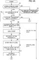
- FIG. 4A is a flowchart illustrating a procedure of filling with hydrogen gas by the hydrogen filling system.
- FIG. 4B is a flowchart illustrating a procedure of filling with the hydrogen gas by the hydrogen filling system.
- FIG. 5 is a time chart schematically illustrating a flow of filling with the hydrogen gas, which is realized by the flowchart in FIGS. 4A and 4B .
- FIG. 1 is a diagram illustrating a configuration of a hydrogen filling system S to which a hydrogen gas filling method according to the embodiment is applied.
- the hydrogen filling system S is configured of a combination of a hydrogen station 9 having a supply source of compressed hydrogen gas and a fuel cell vehicle M (hereinafter, simply referred to as a "vehicle M") having a hydrogen tank that contains the hydrogen gas supplied from the hydrogen station 9.
- a hydrogen gas filling method according to the embodiment is a method of filling the tank of the vehicle M with hydrogen gas from the hydrogen station 9 and is realized by the hydrogen filling system S.
- a configuration on the vehicle M side will be first described, and then a configuration of the hydrogen station 9 side will be described.
- the vehicle M is a fuel cell motorcycle that includes a tank which accumulates hydrogen gas and a fuel cell system (not illustrated) which generates electric power by using, as fuel gas, air and hydrogen gas accumulated in the tank, and that runs by driving a motor with the electric power generated by the fuel cell system.
- a fuel cell motorcycle that includes a tank which accumulates hydrogen gas and a fuel cell system (not illustrated) which generates electric power by using, as fuel gas, air and hydrogen gas accumulated in the tank, and that runs by driving a motor with the electric power generated by the fuel cell system.
- a case where the vehicle M is the fuel cell motorcycle will be described; however, the invention is not limited thereto.
- the invention can be applied to any moving object, as long as the moving object includes a tank that accumulates hydrogen gas.
- the vehicle M includes a hydrogen tank 31 that stores hydrogen gas supplied from the hydrogen station 9, a vehicle tube system 39 that is extended from the hydrogen tank 31, a fuel cell system (not illustrated) that generates electric power by using the hydrogen gas stored in the hydrogen tank 31 and runs by using the generated electric power, an infrared communication device 5 that transmits a data signal related to the hydrogen tank 31 to the hydrogen station 9, and a communication computing ECU 6 that generates the data signal that is transmitted from the infrared communication device 5.
- a vehicle including the infrared communication device 5 and the communication computing ECU 6 will be described; however, the invention is not limited thereto.
- the invention can also be applied to the vehicle M that does not include the infrared communication device 5 and the communication computing ECU 6.
- the vehicle tube system 39 includes a receptacle 38 in which a filling nozzle 92 to be described below of the hydrogen station 9 is fitted and a check valve 36 that is provided in the vicinity of the receptacle 38 of the vehicle tube system 39 and prevents hydrogen gas from flowing back to the receptacle 38 from the hydrogen tank 31 side.
- An intra-tank temperature sensor 41 and an intra-tank pressure sensor 42 are connected to the communication computing ECU 6.
- the intra-tank temperature sensor 41 detects a temperature of the hydrogen gas in the hydrogen tank 31 and transmits a signal associated with a detection value to the communication computing ECU 6.
- the intra-tank pressure sensor 42 detects a pressure in the hydrogen tank 31 and transmits a signal associated with a detection value to the communication computing ECU 6.
- the communication computing ECU 6 is a microcomputer that is configured of an interface that performs A/D conversion of a detection signal of the sensor 41 or 42 described above, a CPU that performs a signal generating process to be described below, a drive circuit that drives the infrared communication device 5 in a condition determined under the process described above, a storage device that stores various items of data, or the like.
- the unique information includes information on the hydrogen tank 31, which can be identified when manufacturing is performed, such as a volume that is derived from the volume value by the known conversion law, a material of the hydrogen tank, or the like, for example, in addition to the volume value of the hydrogen tank.
- a CPU of the communication computing ECU 6 is triggered to start the signal generating process of generating a signal that is transmitted to the hydrogen station 9 from the infrared communication device 5, when a fuel lid that protects the receptacle 38 is opened.
- the CPU of the communication computing ECU 6 is triggered to end the signal generating process, when the nozzle described above is detached from the receptacle 38, and thereby it is not possible to fill the tank with hydrogen gas.
- a temperature transmission value T IR corresponding to a current value of a temperature in the hydrogen tank, a pressure transmission value P IR corresponding to a current value of a pressure in the hydrogen tank, and a volume transmission value V IR corresponding to a current value of a volume in the hydrogen tank are acquired for each predetermined cycle, and a data signal depending on the values (T IR , P IR , and V IR ) is generated.
- T IR a detection value of the intra-tank temperature sensor 41 at that time is used.
- the pressure transmission value P IR a detection value of the intra-tank pressure sensor 42 at that time is used.
- V IR a value stored in the above-described storage device is used.
- the drive circuit of the communication computing ECU 6 drives (causes flickering of) the infrared communication device 5 in response to an abort signal and the data signal generated by the signal generating process described above. Consequently, the data signal including state information (that is, the temperature transmission value T IR , the pressure transmission value P IR , and the like) and the unique information (that is, the volume transmission value V IR and the like) related to a state in the hydrogen tank is transmitted to the hydrogen station 9.
- state information that is, the temperature transmission value T IR , the pressure transmission value P IR , and the like
- the unique information that is, the volume transmission value V IR and the like
- the hydrogen station 9 includes a pressure accumulator 91 in which high-pressure hydrogen gas to be supplied to the vehicle M is stored, a station tube system 93 reaching the filling nozzle 92 through which hydrogen gas is ejected from the pressure accumulator 91, a shut-off valve 94a and a flow rate control valve 94b which are provided on the station tube system 93, a station ECU 95 that controls the valves 94a and 94b, and an operation panel 99 that can be operated by a user of the hydrogen station 9 (for example, a driver of the vehicle M).
- the station ECU 95 opens and closes the shut-off valve 94a and the flow rate control valve 94b in accordance with a procedure to be described below with reference to FIGS. 2 to 5 and fills the hydrogen tank 31 of the vehicle M with the high-pressure hydrogen gas stored in the pressure accumulator 91.
- an integral tube system is formed by the station tube system 93 which is a component that configures the hydrogen station 9 and the vehicle tube system 39 which is a component that configures the vehicle M.
- the hydrogen tank 31 that is mounted on the vehicle M is connected with the pressure accumulator 91 via the tube system.
- a pre-cooler 96 that cools hydrogen gas is provided.
- the pre-cooler 96 cools hydrogen gas at a position close to a position at which the hydrogen tank 31 is filled, and thereby an increase in temperature of hydrogen gas in the hydrogen tank 31 is limited. Furthermore, it is possible to perform rapid filling.
- various sensors 97a, 97b, 97c, and 97d are connected to the station ECU 95.
- the flow rate sensor 97a is provided between the shut-off valve 94a and the flow rate control valve 94b of the station tube system 93 and transmits a signal associated with a mass of hydrogen gas flowing in the station tube system 93 per unit time, that is, a mass flow rate, to the station ECU 95.
- the station temperature sensor 97b is provided downstream of the pre-cooler 96 on the station tube system 93 and transmits a signal associated with a temperature of hydrogen gas in the station tube system 93 to the station ECU 95.
- the station pressure sensor 97c is provided between the flow rate control valve 94b and the shut-off valve 94a of the station tube system 93 and transmits a signal associated with a pressure of hydrogen gas in the station tube system 93 to the station ECU 95.
- the atmosphere temperature sensor 97d detects a temperature of the atmosphere and transmits a signal associated with a detection value to the station ECU 95.
- an atmosphere temperature that is detected by the atmosphere temperature sensor 97d can be considered as a temperature of hydrogen gas in a fuel tank of the vehicle M when filling is started, in some cases.
- An infrared communication device 98 that communicates with the vehicle M is provided on the filling nozzle 92.
- the infrared communication device 98 is a counterpart of the infrared communication device 5 provided in the vehicle M, and a data signal can be transmitted and received via an infrared between the infrared communication devices 98 and 5.
- the operation panel 99 is a touch panel that detects an input operation for designating a type of tank of the vehicle M by the user.
- a character of "small-sized tank” meaning a hydrogen tank (for example, a tank having a volume smaller than 2.0 kg) that is mounted on a general fuel cell motorcycle
- a character of "regular-sized tank” meaning a hydrogen tank (for example, a tank having a volume of 2.0 kg or larger and smaller than 10.0 kg) that is mounted on the fuel cell vehicle of a general four-wheel regular automobile
- a character of "large-sized tank” meaning a hydrogen tank (for example, a tank having a volume of 10.0 kg or larger) that is mounted on the fuel cell vehicle such as a bus.
- the operation panel 99 transmits a signal indicating that a type of tank that is designated by the user is "small-sized tank” to the station ECU 95. In addition, in a case where the user touches a part displayed as “regular-sized tank”, the operation panel 99 transmits a signal indicating that a type of tank that is designated by the user is “regular-sized tank” to the station ECU 95. In addition, in a case where the user touches a part displayed as "large-sized tank”, the operation panel 99 transmits a signal indicating that a type of tank that is designated by the user is "large-sized tank” to the station ECU 95.
- FIG. 2 is a functional block diagram illustrating a configuration of a control circuit for filling flow rate control by the station ECU 95.
- a gas filling step from a start to an end of filling with hydrogen gas in the hydrogen station is divided into an initial filling step of first filling the hydrogen tank with hydrogen gas tentatively in order to know a state of the hydrogen tank of the vehicle and a main filling step of filling the hydrogen tank with hydrogen gas under filling flow rate control performed by the station ECU 95 such that a target pressure increase ratio is set and the target pressure increase ratio is realized (refer to flowcharts or the like in FIGS. 4A and 4B to be described below).
- FIG. 2 illustrates modules 71 to 78 that realize the filling flow rate control particularly in the main filling step.
- the mass-averaged temperature computing unit 71 calculates a mass-averaged temperature MAT of hydrogen gas having passed through the pre-cooler, based on the detection value of the station temperature sensor and the detection value of the flow rate sensor.
- the mass-averaged temperature MAT is used to set the target pressure increase ratio in the target pressure increase ratio setting unit 72. Besides, immediately after the main filling step is started, about tens of seconds are taken for the detection value of the station temperature sensor to actually reach a temperature of gas flowing out of the pre-cooler.
- the mass-averaged temperature computing unit 71 outputs, as the mass-averaged temperature MAT, a value set in advance without using the detection value of the station temperature sensor during elapse of about tens of seconds (more specifically, 30 seconds, for example) from the start of the main filling step.
- the target pressure increase ratio setting unit 72 sets a target pressure increase ratio ⁇ P ST corresponding to a target of a pressure increase ratio of the hydrogen tank in the main filling step, based on the mass-averaged temperature MAT that is calculated by the mass-averaged temperature computing unit 71. More specifically, the target pressure increase ratio setting unit 72 performs the following computations serially, thereby, setting the target pressure increase ratio ⁇ P ST .
- the target pressure increase ratio setting unit 72 performs computation shown in Equation (2) to be described below, based on the mass-averaged temperature MAT and a detection value T amb of the atmosphere temperature sensor 97d, thereby calculating a period of filling time t final corresponding to a period of time from a predetermined filling start time point t ini to a predetermined scheduled filling end time point.
- t final a T amb MAT 3 + b T amb MAT 2 + c T amb MAT + d T amb
- values of coefficients "a”, “b”, “c”, and “d” are calculated by retrieving a coefficient value determining map that has been selected in advance, based on the detection values T amb of the atmosphere temperature sensor 97d, respectively.
- the coefficient value determining map is a map obtained by associating an atmosphere temperature with the values of the four coefficients.
- a plurality of coefficient value determining maps are set for each volume of the hydrogen tank.
- the target pressure increase ratio setting unit 72 selects a coefficient value determining map corresponding to the estimation value V' and calculates the period of filling time t final based on the selected coefficient value determining map.
- the target pressure increase ratio setting unit 72 sets the target pressure increase ratio ⁇ P ST such that the hydrogen tank is fully filled after the period of filling time t final from the filling start time point t ini .
- the target pressure increase ratio setting unit 72 sets a start time point of the initial filling step, that is, a performing time point of pre-shot filling to be described below, as the filling start time point t ini .
- the target filling pressure computing unit 73 calculates a target filling pressure P TRGT corresponding to a target value of a filling pressure after a predetermined period of time by using the target pressure increase ratio ⁇ P ST set by the target pressure increase ratio setting unit 72 and a detection value P ST (hereinafter, also referred to as a "filling pressure") of the station pressure sensor.
- the feedback controller 74 determines an instruction opening degree of the flow rate control valve such that a filling pressure P ST becomes the target filling pressure P TRGT , based on the known feedback control law and inputs the instruction opening degree to a drive device (not illustrated) of the flow rate control valve.
- the drive device adjusts an opening degree of the flow rate control valve so as to realize the instruction opening degree. Consequently, in the main filling step, filling is performed with hydrogen gas such that the target pressure increase ratio ⁇ P ST set by the target pressure increase ratio setting unit 72 is realized.
- the filling completion determining unit 75 determines whether or not the filling with hydrogen gas is completed and sets the instruction opening degree to 0 so as to complete the filling with hydrogen gas in the case of determining that the filling is completed. For example, in the filling completion determining unit 75, the following two filling completion conditions are defined.
- a first filling completion condition is that the filling pressure P ST exceeds a predetermined completion threshold value.
- the filling completion determining unit 75 determines that the hydrogen tank reaches full filling and sets the instruction opening degree to 0 so as to complete the filling with hydrogen gas in the case of determining that the filling is completed in a case where the filling pressure P ST detected by the pressure sensor exceeds the completion threshold value described above.
- a second filling completion condition is that the instruction opening degree is set to 0 such that the filling with hydrogen gas is stopped in order to prevent overfilling in a case where the type of hydrogen tank designated by the user is the small-sized tank, and the volume estimation value V' calculated by the volume estimating unit 76 to be described below is out of a predetermined range.
- the initial pressure estimating unit 77 estimates an initial tank pressure which is a pressure of the hydrogen tank before the initial filling step is started, that is, immediately before the hydrogen tank starts to be filled with hydrogen gas from the hydrogen station. More specifically, after pre-shot filling to be described below, which is included in the initial filling step, is performed, the initial pressure estimating unit 77 calculates an estimation value ⁇ 0 real of initial tank density from Equation (3) to be described below by using a pressure in the station tube system detected by the station pressure sensor, the volume of the hydrogen tank, or the like. Further, the initial pressure estimating unit inputs the estimation value ⁇ 0 real of the initial tank density into a state equation of gas, thereby, calculating an estimation value P 0 of the initial tank pressure.
- ⁇ 0 real ⁇ 0 ′ ⁇ V PRE V ⁇ pre ⁇ ⁇ pre ′
- Equation (3) described above is derived from a principle of conservation of mass that is established before and after the pre-shot filling.
- V PRE represents a volume in a storage zone (more specifically, a zone from the shut-off valve to the flow rate control valve in the station tube system) in which pressure increases temporarily during the pre-shot filling, and a predetermined value is used as V PRE .
- ⁇ pre represents gas density in the storage zone before the pre-shot filling, a value calculated by retrieving a predetermined map based on a pressure and a temperature of a gas in the storage zone before the pre-shot filling is used as ⁇ pre , for example.
- Equation (3) described above " ⁇ ' pre " represents gas density in the storage zone after the pre-shot filling, a value calculated by retrieving a predetermined map based on a pressure and a temperature of a gas in the storage zone after the pre-shot filling is used as ⁇ ' pre , for example.
- ⁇ ' 0 represents gas density in the hydrogen tank after the pre-shot filing, and the same value as “ ⁇ ' pre " is used as ⁇ ' 0 , for example.
- V is the volume of the hydrogen tank, the volume transmission value V IR is used in a case where it is possible to acquire the volume transmission value V IR that is transmitted from the vehicle side.
- a predetermined value which is a volume value of a general small-sized tank is used as "V" in Equation (3) described above.
- the tube system pressure loss estimating unit 78 calculates a pressure loss value corresponding to an estimation value of a pressure loss occurring in the station tube system and the vehicle tube system (hereinafter, also collectively referred to as a "connection tube system").
- FIG. 3 is a time chart for illustrating a procedure of calculating the pressure loss value in the connection tube system by the tube system pressure loss estimating unit 78. More specifically, FIG. 3 illustrates a change in pressure and flow rate during the initial filling step and the main filling step.
- a solid line represents a temporal change in pressure detected by the station pressure sensor
- a dashed line represents a temporal change in pressure in the hydrogen tank
- a dot-and-dash line represents a temporal change in flow rate detected by the flow rate sensor.
- FIG. 3 is a time chart for illustrating a procedure of calculating the pressure loss value in the connection tube system by the tube system pressure loss estimating unit 78. More specifically, FIG. 3 illustrates a change in pressure and flow rate during the initial filling step and the main filling step.
- a solid line represents a temporal change in pressure detected by the station pressure sensor
- a dashed line represents a temporal change in pressure in the hydrogen tank
- FIG. 3 illustrates a case where the main filling step is executed after a time point t1, after the initial filling step (pre-shot filling) is executed between a time point t0 and the time point t1.
- the initial filling step pre-shot filling
- t3 and t5 a case where filling is temporarily stopped so as to perform a leak checking process is illustrated between time points t3 and t5, for example.
- connection tube system while hydrogen gas flows in the connection tube system, a significant pressure loss occurs depending on a structure of a flow channel in the connection tube system, and thus the pressure in the hydrogen tank is lower than the pressure detected by the station pressure sensor, as illustrated in FIG. 3 .
- Equation (4) described above “dm” represents a mass flow rate of hydrogen gas that flows in the connection tube system, and a detection value of the flow rate sensor is used as dm, for example.
- ⁇ represents density of hydrogen gas, and a value calculated by inputting the detection value of the station pressure sensor in the known function and the detection value of the station temperature sensor is used as ⁇ , for example.
- k 0 is a coefficient related to the pressure loss occurring in the connection tube system and will be referred to as a shape factor coefficient, hereinafter.
- the shape factor coefficient k 0 is a coefficient that is determined, depending on a shape of a flow channel of hydrogen gas, which is formed mainly in the connection tube system.
- the tube system pressure loss estimating unit 78 determines a value of the shape factor coefficient k 0 described above by using any opportunity of temporarily stopping the filling during the main filling step and estimates the pressure loss dP loss at any time point based on Equation (4) described above, by using the determined shape factor coefficient k 0 , the detection value of the flow rate sensor, and an estimation value of the density of hydrogen gas.
- the opportunity of temporarily stopping the filling during the main filling step can be gained during execution of the leak checking process in a case where the leak checking process is obliged by law to be executed during the main filling step, for example.
- filling is temporarily stopped to perform replacement of the hydrogen tank on the station side during the main filling step in some cases, for example, and thus it is possible to gain opportunity during execution of such tank replacement.
- the elapse of tens of seconds (for example, 30 seconds) from the start of the main filling step is set as a period in which temperatures of the pre-cooler and the station tube system become equal to each other. During the period filling is performed under a constant pressure increase ratio, and then filling is performed under a variable pressure increase ratio in some cases.
- the filling may be temporarily stopped at a timing at which a filling control method is switched depending on the elapse of tens of seconds from the start of the main filling step as described above, and the shape factor coefficient k 0 may be estimated as described above.
- a predetermined value obtained by performing a preliminary test or the like or a value acquired by such an algorithm described above when the previous main filling step is ended may be used as the shape factor coefficient k 0 .
- the tube system pressure loss estimating unit 78 calculates a value of the shape factor coefficient k 0 based on Equation (5-1) to be described below derived from Equation (4) described above.
- Equation (5-1) to be described below “ ⁇ P PRE " is the diminution of the pressure in the connection tube system when the main filling is temporarily stopped at the time point t3, as illustrated in FIG. 3 , and is calculated by using the detection value of the station pressure sensor before and after the main filling is temporarily stopped, for example.
- dm PRE is a mass flow rate of hydrogen gas that flows in the connection tube system during the main filling (before the filling is temporarily stopped), and the detection value of the flow rate sensor at the time point t2 immediately before the time point t3 is used as dm PRE .
- ⁇ PRE density of hydrogen gas in the connection tube system during the main filling (before the filling is temporarily stopped), and a value calculated by inputting, in the known density function ⁇ , an average value of a detection value P (t2) of the station pressure sensor at the time point t2 immediately before the time point t3 and a detection value P (t4) of the station pressure sensor at the time point t4 immediately after the time point t3 may be used as ⁇ PRE and a detection value T of the station temperature sensor at the time point t3, as shown in Equation (5-2) to be described below.
- k 0 ⁇ P PRE ⁇ PRE dm PRE 2
- ⁇ PRE ⁇ P t 1 + P t 3 2 T
- the volume estimating unit 76 estimates the volume of the hydrogen tank that is connected to the hydrogen station. More specifically, the volume estimating unit 76 performs computation shown in Equation (6) to be described below based on the detection value of the flow rate sensor, the detection value of the station pressure sensor, the predetermined volume value of the connection tube system, and the pressure loss value calculated by the tube system pressure loss estimating unit 78, thereby, calculating the estimation value V' of the volume of the hydrogen tank.
- Equation (6) to be described below is derived, based on a real gas equation established at any time point t 1 during the filling with hydrogen gas.
- V ′ ⁇ M + ⁇ 0 V tube z 1 RT 1 P 1 ⁇ V tube / 1 ⁇ ⁇ 0 z 1 RT 1 P 1
- Equation (6) represents a mass of hydrogen gas passing through the connection tube system from an estimation time point t 0 of the initial pressure by the initial pressure estimating unit 77 to the time point t 1 , and a value obtained by integrating detection values of the flow rate sensor is used as ⁇ M, for example.
- V tube represents a volume value of the connection tube system, and a predetermined value is used as V tube .
- the connection tube system has a configuration in which the station tube system of which the volume value is known is connected with the vehicle tube system of which the volume value is not known. However, in the entire connection tube system, a proportion of the vehicle tube system is small, and thus the volume value of the station tube system is used as "V tute " described above.
- T 1 represents a temperature of hydrogen gas in the hydrogen tank at the time point t 1 , and the detection value of the atmosphere temperature sensor is used as T 1 , for example.
- R represents a gas constant, and a predetermined value is used as R.
- Equation (6) represents a pressure in the hydrogen tank at the time point t 1 , and a value thereof is calculated in accordance with Equation (7) to be described below.
- P st represents a pressure in the connection tube system at the time point t 1
- the detection value of the station pressure sensor at the time point t 1 is used as P st , for example.
- dP loss est represents a pressure loss occurring in the connection tube system from the time point t 0 to the time point t 1
- the pressure loss value calculated by the tube system pressure loss estimating unit 78 from the time point t 0 to the time point t 1 is used as dP loss est .
- P 1 P st ⁇ dP loss est
- z 1 represents a compression coefficient of hydrogen gas in the hydrogen tank at the time point t 1 .
- a value of the compression coefficient z 1 for example, a value calculated by inputting "T 1 ", which is the temperature of hydrogen gas in the hydrogen tank at the time point t 1 , and "P 1 ", which is the pressure in the hydrogen tank at the time point t 1 , in the known function f as will be shown in Equation (8) to be described below, is used.
- z 1 f T 1 P 1
- Equation (6) is density of hydrogen gas in the hydrogen tank at the time point t 0 .
- the detection value of the atmosphere temperature sensor is used as the temperature T 0 of hydrogen gas in the hydrogen tank at the time point t 0 .
- ⁇ 0 ⁇ P 0 T 0
- Equation (6) described above for estimating the tank volume is derived by using approximate equations shown as Equations (10-2) and (10-3) to be described below in a state equation (refer to Equation (10-1) to be described below) that is established at any time point t 1 .
- FIGS. 4A and 4B are flowcharts illustrating a procedure of filling the tank with hydrogen gas by the hydrogen filling system. This process is started as the filling nozzle of the hydrogen station is connected with the receptacle of the vehicle, and the filling with hydrogen gas becomes possible. As illustrated in FIGS. 4A and 4B , a step from the start to the end of the filling with the hydrogen gas is divided into the initial filling step (refer to S5 to S7) of tentatively filling the hydrogen tank with hydrogen gas and the main filling step (refer to S8 to S13) of filling the hydrogen tank with hydrogen gas under the predetermined target pressure increase ratio.
- the station ECU discriminates whether or not the type of hydrogen tank that is designated by the user is the small-sized tank or the large-sized tank.
- the station ECU performs the filling with hydrogen gas in accordance with the algorithm that is defined for the regular-sized tank (refer to S2).
- a filling procedure of hydrogen gas for the regular-sized tank is described in detail in PCT International Publication No. WO2017/159314 by the applicant of the present application, and thus the detailed description thereof is omitted.
- the station ECU discriminates whether or not the currently connected vehicle is communicable (refer to S3). In a case where the discrimination in S3 is YES, the station ECU discriminates whether or not the volume transmission value V IR that is transmitted from the vehicle can be received (refer to S4). In a case where the discrimination in S4 is YES, the station ECU proceeds to S5. In a case where the discrimination in S4 is NO, the station ECU stops the filling (refer to S13). In addition, in a case where the discrimination in S3 is NO, the station ECU proceeds to S5.
- the station ECU executes the pre-shot filling. More specifically, while the flow rate control valve provided on the station tube system is closed, the shut-off valve provided upstream side of the flow rate control valve is opened, and the pressure in the station tube system is increased until the detection value of the station pressure sensor provided upstream side of the flow rate control valve. Then, the shut-off valve is closed. Consequently, a storage zone from the flow rate control valve to the shut-off valve in the station tube system is filled with an amount of hydrogen gas corresponding to the pressure. Next, while the shut-off valve is closed, the flow rate control valve is opened. Consequently, hydrogen gas compressed in the storage zone described above flows into the hydrogen tank at once, and the insides of the hydrogen tank and the station tube system are uniformized.
- the pre-shot filling is executed as described above, and a time point, at which the pre-shot filling is started, is set as the filling start time point t ini that is needed when the period of filling time t final is determined by the above-described target pressure increase ratio setting unit.
- the station ECU temporarily stops the filling with hydrogen gas and executes the leak check of checking filling leak.
- the initial pressure estimating unit of the station ECU performs computation shown in Equation (3) described above, thereby, calculating the estimation value P 0 of a tank initial pressure which is the pressure in the hydrogen tank immediately before the pre-shot filling is started.
- the station ECU starts the main filling.
- filling with hydrogen gas is performed such that the target pressure increase ratio determined in the target pressure increase ratio setting unit is realized.
- the target pressure increase ratio setting unit retrieves the coefficient value determining map based on the predetermined mass-averaged temperature MAT, thereby, determining the period of filling time t final .
- the volume of the hydrogen tank is not fixed at the start of the main filling.
- the target pressure increase ratio setting unit selects the coefficient value determining map depending on the volume value obtained via communication.
- a map determined to have slowest filling speed is selected from a plurality of coefficient determining maps set in advance.
- the tube system pressure loss estimating unit of the station ECU acquires a value of the shape factor coefficient k 0 which is needed when the pressure loss value is calculated at any time point.
- the tube system pressure loss estimating unit reads a value stored in a memory not illustrated, thereby, acquiring the value of the shape factor coefficient k 0 .
- the tube system pressure loss estimating unit temporarily stops the filling with hydrogen gas and calculates the value of the shape factor coefficient k 0 by using a period in which the filling with hydrogen gas is temporarily stopped.
- the volume estimating unit of the station ECU estimates the volume of the connected hydrogen tank. More specifically, the volume estimating unit performs computation shown in Equation (6) described above based on the detection value of the flow rate sensor or the station pressure sensor at any two time points t 0 and t 1 during the elapse of 30 seconds after the start of the main filling from the start of the pre-shot filling, thereby, calculating the estimation value V' of the volume of the hydrogen tank.
- the filling completion determining unit of the station ECU discriminates whether or not the calculated estimation value V' of the tank volume is within a predetermined error range.
- the error range is set in a range [V IR - ⁇ , V IR + ⁇ ] with a value, which is obtained by subtracting an allowable error ⁇ from the volume transmission value V IR , as a lower limit and a value, which is obtained by adding the allowable error ⁇ to the volume transmission value V IR , as an upper limit.
- the error range is set to a predetermined range so as to include the volume of a general small-sized tank.
- the station ECU stops the filling (refer to S14).
- the target pressure increase ratio setting unit of the station ECU re-selects the coefficient value determining map based on the acquired estimation value V' of the tank volume (refer to S12).
- the station ECU continues the main filling under the coefficient value determining map that is re-selected in S12, in association with the elapse of 30 seconds from the start of the main filling in S8.
- FIG. 5 is a time chart schematically illustrating a flow of the filling with the hydrogen gas, which is realized by the flowchart in FIGS. 4A and 4B .
- a solid line represents a change in pressure in the hydrogen tank.
- the hydrogen station executes the pre-shot filling (refer to S5 in FIG. 4A ) from the time point t0 to the time point t1 and sets the time point t0, at which the pre-shot filling is started, as the filling start time point t ini .
- the hydrogen station executes the leak check from the time point t1 to the time point t2 (refer to S6 in FIG. 4A ).
- the hydrogen station executes the leak check from the time point t1 to the time point t2, thereby, calculating the shape factor coefficient k 0 that is needed to estimate the pressure loss value at any time point by using a period during which the filling with hydrogen gas is stopped (refer to S9 in FIG. 4A ), and estimating the initial pressure P 0 of the hydrogen tank (refer to S7 in FIG. 4A ).
- the hydrogen station starts the main filling at the time point t2 (refer to S8 in FIG. 4A ).
- the target pressure increase ratio setting unit performs the filling under a constant target pressure increase ratio based on the fixed mass-averaged temperature MAT during the elapse of tens of seconds from the start of the main filling at the time point t2.
- the hydrogen station estimates the volume of the hydrogen tank (refer to S10 in FIG. 4A ) and further re-selects the coefficient value determining map by using the estimated volume (refer to S12 in FIG. 4B ).
- the hydrogen station sets the target pressure increase ratio under the coefficient value determining map re-selected as described above, in association with the elapse of tens of seconds from the start of the main filling at the time point t3, and the filling with hydrogen gas is performed to realize the target pressure increase ratio.
- the target pressure increase ratio setting unit retrieves the coefficient value determining map based on the mass-averaged temperature MAT, thereby, calculating the period of filling time t final , and sets the target pressure increase ratio such that the hydrogen tank is fully filled at the time point t4 after the period of filling time t final elapses from the filling start time point t ini set to the time point t0 as described above.
Landscapes
- Engineering & Computer Science (AREA)
- Mechanical Engineering (AREA)
- General Engineering & Computer Science (AREA)
- Physics & Mathematics (AREA)
- Fluid Mechanics (AREA)
- General Physics & Mathematics (AREA)
- Filling Or Discharging Of Gas Storage Vessels (AREA)
Claims (7)
- Gasbefüllungsverfahren zum Befüllen eines Tanks (31) mit einem Gas von einer Zufuhrquelle (91) durch ein Gasbefüllungssystem (S), das eine Gaszufuhrvorrichtung (9), die die Zufuhrquelle (91) von komprimiertem Gas aufweist, ein bewegliches Objekt (M), das den das Gas enthaltenden Tank (31) aufweist, ein Rohrsystem (39, 93), das die Zufuhrquelle (91) mit dem Tank (31) verbindet, sowie einen Strömungsratensensor (97a) und einen Drucksensor (97c), die an dem Rohrsystem (39, 93) vorgesehen sind, enthält, wobei das Gasbefüllungsverfahren aufweist:einen Volumenschätzschritt zum Schätzen eines Tankvolumens (V'), das ein Volumen des Tanks (31) ist, basierend auf Detektionswerten des Strömungsratensensors (97a) und des Drucksensors (97c) und eines Volumenwerts des Rohrsystems (39, 93) nach einem Beginn des Befüllens des Tanks (31) mit dem Gas von der Zufuhrquelle (91),wobei in dem Volumenschätzschritt das Tankvolumen (V') basierend auf dem Volumenwert des Rohrsystems (39, 93) unter Berücksichtigung des Gasanteils geschätzt wird, der den Tank (31) nicht füllt, aber von dem von der Zufuhrquelle (91) abgegebenen Gas in dem Rohrsystem (39, 93) verbleibt.
- Das Gasbefüllungsverfahren nach Anspruch 1, das ferner aufweist:einen Koeffizientenberechnungsschritt zum Berechnen eines Werts eines Koeffizienten in Bezug auf einen Druckverlust, der auftritt, wenn das Gas in dem Rohrsystem (39, 93) fließt, basierend auf den Detektionswerten des Strömungsratensensors (97a) und des Drucksensors (97c), wenn das Befüllen des Tanks (31) mit dem Gas von der Zufuhrquelle (91) gestoppt wird,wobei in dem Volumenschätzschritt das Tankvolumen basierend auf den Detektionswerten des Strömungsratensensors (97a) und des Drucksensors (97c), dem Volumenwert des Rohrsystems (39, 93) und einem basierend auf dem Wert des Koeffizienten berechneten Druckverlustwert geschätzt wird.
- Das Gasbefüllungsverfahren nach Anspruch 1 oder 2,
wobei ein Schritt zum Befüllen des Tanks (31) mit dem Gas unterteilt wird in einen anfänglichen Befüllungsschritt zum Befüllen des Tanks mit dem Gas, um einen Zustand des Tanks (31) zu erkennen, sowie einen Hauptfüllschritt zum Befüllen des Tanks (31) mit dem Gas, um ein vorbestimmtes Solldruck-Anstiegsverhältnis zu realisieren, und
wobei in dem Volumenschätzschritt während des Hauptfüllschritts das Tankvolumen basierend auf den Detektionswerten des Strömungsratensensors (97a) und des Drucksensors (97c) geschätzt wird. - Das Gasbefüllungsverfahren nach Anspruch 3, das ferner aufweist:einen Anfangsdruckschätzschritt zum Schätzen eines Anfangsdrucks des Tanks (31) vor einem Start des anfänglichen Befüllungsschritts basierend auf dem Detektionswert des Drucksensors (97c), nachdem der anfängliche Befüllungsschritt gestartet ist,wobei in dem Hauptfüllschritt das Befüllen des Gases gestartet wird, unmittelbar nachdem der Anfangsdruckschätzschritt beendet wird, und das Befüllen des Gases durchgeführt wird, um ein Solldruckanstiegsverhältnis zu realisieren, das basierend auf einem in dem Anfangsdruckschätzschritt berechneten Schätzwert des Anfangsdrucks gesetzt wird.
- Das Gasbefüllungsverfahren nach einem der Ansprüche 1 bis 4, wobei, wenn ein in dem Volumenschätzschritt berechneter Schätzwert des Tank-(31)-Volumens außerhalb eines vorbestimmten Bereichs liegt, das Befüllen des Tanks (31) mit dem Gas von der Zufuhrquelle (91) gestoppt wird.
- Das Gasbefüllungsverfahren nach Anspruch 3 oder 4,
wobei das Gasbefüllungssystem eine Eingabevorrichtung (99) enthält, die eine von einem Benutzer durchgeführte Bedienung empfängt, um einen Tank-Typ zu benennen,
wobei das Gasbefüllungsverfahren ferner einen Bestimmungsschritt aufweist, um zu bestimmen, ob ein über die Eingabevorrichtung (99) benannter Tank-Typ ein klein bemessener Tank, dessen Volumen kleiner als ein vorbestimmtes Standardvolumen ist, oder ein groß bemessener Tank, dessen Volumen größer als das Standardvolumen ist, ist, und wobei in dem Hauptfüllschritt eine Füllzeitdauer, die der Zeitdauer ab einem vorbestimmten Befüllungsstartzeitpunkt bis zu einem geplanten Befüllungsendzeitpunkt entspricht, während des Befüllens des Gases basierend auf den Detektionswerten des Drucksensors (97c) und des Strömungsratensensors (97a) berechnet wird, wobei das Solldruckanstiegsverhältnis derart bestimmt wird, dass, basierend auf der Füllzeitdauer, der Tank (31) zu dem geplanten Befüllungsendzeitpunkt vollständig gefüllt ist, und der Befüllungsstartzeitpunkt auf einen Startzeitpunkt des anfänglichen Befüllungsschritts gesetzt wird, wenn im Bestimmungsschritt ein Tank-Typ als klein bemessener Tank bestimmt wird. - Das Gasbefüllungsverfahren nach einem der Ansprüche 1 bis 6,
wobei in dem Volumenschätzschritt ein Schätzwert V' des Tankvolumens basierend auf der unten beschriebenen Gleichung (1) berechnet wird.
Applications Claiming Priority (1)
| Application Number | Priority Date | Filing Date | Title |
|---|---|---|---|
| JP2018069351A JP6721626B2 (ja) | 2018-03-30 | 2018-03-30 | ガス充填方法 |
Publications (2)
| Publication Number | Publication Date |
|---|---|
| EP3550198A1 EP3550198A1 (de) | 2019-10-09 |
| EP3550198B1 true EP3550198B1 (de) | 2020-12-16 |
Family
ID=66000985
Family Applications (1)
| Application Number | Title | Priority Date | Filing Date |
|---|---|---|---|
| EP19165770.9A Not-in-force EP3550198B1 (de) | 2018-03-30 | 2019-03-28 | Gasbefüllungsverfahren |
Country Status (4)
| Country | Link |
|---|---|
| US (1) | US11326740B2 (de) |
| EP (1) | EP3550198B1 (de) |
| JP (1) | JP6721626B2 (de) |
| CN (1) | CN110319343B (de) |
Families Citing this family (20)
| Publication number | Priority date | Publication date | Assignee | Title |
|---|---|---|---|---|
| US11993143B2 (en) * | 2019-07-02 | 2024-05-28 | Volvo Truck Corporation | Fuel gas system for a vehicle |
| CN110848566B (zh) * | 2019-12-13 | 2024-04-05 | 上海机动车检测认证技术研究中心有限公司 | 一种加氢装置及加氢方法 |
| EP3879164A1 (de) * | 2020-03-09 | 2021-09-15 | Nproxx B.V. | Befüllvorrichtung und verfahren zum befüllen |
| US11293595B2 (en) * | 2020-04-01 | 2022-04-05 | Mirae EHS-code Research Institute | Hydrogen fueling system and method based on real-time communication information from CHSS for fuel cell |
| US11604087B2 (en) * | 2020-09-21 | 2023-03-14 | China Energy Investment Corporation Limited | Method and apparatus for calculating volume of compressed gas storage vessel, computer, and medium |
| CN114838284B (zh) * | 2021-02-01 | 2024-11-29 | 国家能源投资集团有限责任公司 | 车辆加氢方法和车辆加氢装置 |
| CN121576518A (zh) | 2021-07-19 | 2026-02-27 | 丰田自动车株式会社 | 氢填充方法、氢填充装置、程序、记录介质 |
| CN113707912B (zh) * | 2021-08-26 | 2023-02-17 | 四川华能氢能科技有限公司 | 一种氢燃料电池供氢系统 |
| JP7852216B2 (ja) * | 2021-09-01 | 2026-04-28 | スズキ株式会社 | 水素補給制御装置、水素補給装置及び水素補給プログラム |
| CN116357882B (zh) * | 2021-12-28 | 2025-08-12 | 本田技研工业株式会社 | 气体填充方法 |
| US20260031372A1 (en) * | 2022-03-30 | 2026-01-29 | Tatsumi Ryoki Co., Ltd | Electric power supply system |
| JP7789641B2 (ja) * | 2022-09-01 | 2025-12-22 | 本田技研工業株式会社 | 容量推定装置、水素充填装置および容量推定方法 |
| JP2024038657A (ja) * | 2022-09-08 | 2024-03-21 | 本田技研工業株式会社 | ガス充填方法 |
| EP4425037A1 (de) * | 2023-03-03 | 2024-09-04 | Linde GmbH | Verfahren zum bestimmen einer grösse eines tanks |
| US20240302000A1 (en) * | 2023-03-07 | 2024-09-12 | Boyd Hydrogen LLC | Compressed hydrogen vehicle fueling system having sonic choke flow control |
| FR3150262B1 (fr) * | 2023-06-20 | 2025-05-09 | Air Liquide | Installation et procédé de fourniture d’hydrogène liquéfié |
| FR3151656B1 (fr) * | 2023-07-25 | 2025-07-18 | Air Liquide | Procédé d’estimation d’un volume de réservoir à remplir à partir d’une station de distribution d’un fluide sous pression. |
| CN118224510B (zh) * | 2023-07-31 | 2025-12-16 | 比亚迪股份有限公司 | 充放气设备的控制方法、装置、车辆及可读存储介质 |
| CN118224502B (zh) * | 2023-07-31 | 2026-03-20 | 比亚迪股份有限公司 | 充放气设备的控制方法、装置、车辆及可读存储介质 |
| CN120332658B (zh) * | 2025-06-19 | 2025-09-05 | 浙江浙能航天氢能技术有限公司 | 一种车载气瓶的泄漏检测方法、装置及电子设备 |
Family Cites Families (18)
| Publication number | Priority date | Publication date | Assignee | Title |
|---|---|---|---|---|
| US6691061B1 (en) * | 1996-06-04 | 2004-02-10 | Warren Rogers Associates, Inc. | Method and apparatus for monitoring operational performance of fluid storage systems |
| JP4327559B2 (ja) * | 2003-08-15 | 2009-09-09 | 大陽日酸株式会社 | 燃料充てん方法 |
| US7177780B2 (en) * | 2005-01-14 | 2007-02-13 | Flying J, Inc. | Methods and systems for measuring physical volume |
| TW200638041A (en) * | 2005-04-29 | 2006-11-01 | Asia Pacific Fuel Cell Tech | Method for measuring residue of hydrogen in hydrogen tank |
| FR2948438B1 (fr) * | 2009-07-27 | 2015-04-03 | Air Liquide | Procede d'estimation du volume d'un reservoir de gaz sous pression. |
| NO332687B1 (no) * | 2009-10-21 | 2012-12-10 | Nel Hydrogen As | Fremgangsmate for operasjonen og styring ved gassfylling |
| JP5115565B2 (ja) * | 2010-02-15 | 2013-01-09 | トヨタ自動車株式会社 | 車両 |
| JP2011226558A (ja) * | 2010-04-20 | 2011-11-10 | Iwatani Internatl Corp | 気体充填装置及び気体充填方法 |
| EP2652385A2 (de) * | 2010-12-16 | 2013-10-23 | Air Products and Chemicals, Inc. | Verfahren zum befüllen eines gasspeicherbehälters |
| KR101222874B1 (ko) * | 2012-06-26 | 2013-01-16 | 주식회사가스로드 | 압력과 체적을 이용한 압력용기의 충전량 측정 시스템 및 방법 |
| FR3008473B1 (fr) * | 2013-07-11 | 2015-07-17 | Air Liquide | Procede et station de remplissage de gaz |
| JP6215090B2 (ja) * | 2014-03-05 | 2017-10-18 | 大陽日酸株式会社 | 水素ガス充填制御装置、水素ガス充填方法及びコンピュータプログラム |
| JP6179057B2 (ja) * | 2014-03-06 | 2017-08-16 | 大陽日酸株式会社 | 燃料ガス充填システム、燃料ガス充填方法及びコンピュータプログラム |
| EP2933612A1 (de) * | 2014-04-16 | 2015-10-21 | Sartorius Stedim Biotech GmbH | Verfahren zur Bestimmung des Innenvolumens einer Filter- oder Beutelvorrichtung, Computerprogrammprodukt und Testvorrichtung zur Durchführung des Verfahrens |
| JP6001600B2 (ja) * | 2014-06-26 | 2016-10-05 | 株式会社日本自動車部品総合研究所 | ガス供給部を制御するシステムおよびガス充填方法 |
| JP6514611B2 (ja) * | 2015-09-10 | 2019-05-15 | 本田技研工業株式会社 | ガス充填方法 |
| CN108779895B (zh) * | 2016-03-15 | 2020-11-13 | 本田技研工业株式会社 | 气体填充方法 |
| JP2018069351A (ja) | 2016-10-25 | 2018-05-10 | 有限会社岩▲崎▼目立加工所 | 鋸歯チップ取付用スリットの形成方法及び装置 |
-
2018
- 2018-03-30 JP JP2018069351A patent/JP6721626B2/ja not_active Expired - Fee Related
-
2019
- 2019-03-28 EP EP19165770.9A patent/EP3550198B1/de not_active Not-in-force
- 2019-03-29 CN CN201910256091.8A patent/CN110319343B/zh not_active Expired - Fee Related
- 2019-03-29 US US16/370,061 patent/US11326740B2/en active Active
Non-Patent Citations (1)
| Title |
|---|
| None * |
Also Published As
| Publication number | Publication date |
|---|---|
| CN110319343A (zh) | 2019-10-11 |
| EP3550198A1 (de) | 2019-10-09 |
| JP6721626B2 (ja) | 2020-07-15 |
| JP2019178758A (ja) | 2019-10-17 |
| US11326740B2 (en) | 2022-05-10 |
| US20190301678A1 (en) | 2019-10-03 |
| CN110319343B (zh) | 2021-07-09 |
Similar Documents
| Publication | Publication Date | Title |
|---|---|---|
| EP3550198B1 (de) | Gasbefüllungsverfahren | |
| CN108779895B (zh) | 气体填充方法 | |
| US11193632B2 (en) | Gas filling method | |
| JP6150839B2 (ja) | 燃料充填システム及びその燃料充填方法 | |
| US11136951B2 (en) | Gas fueling method | |
| CN115698579B (zh) | 用于调整压力容器的提取管路中的压力的控制单元和方法 | |
| CN102713404B (zh) | 燃料气体站、燃料气体填充系统、燃料气体供给方法 | |
| US10465849B2 (en) | Gas filling method | |
| JP6514612B2 (ja) | ガス充填方法 | |
| CN102667303B (zh) | 气体填充装置及气体填充方法 | |
| JP2015124830A (ja) | 燃料充填システム | |
| CN102575808B (zh) | 气体填充装置、气体填充系统、气体填充方法以及移动装置 | |
| JP5328617B2 (ja) | ガス充填システム、ガス充填方法、車両 | |
| CN113137564B (zh) | 用于灌注一个或多个储罐的站和方法 | |
| EP4206518B1 (de) | Gasfüllverfahren | |
| JP5716344B2 (ja) | ガス充填システム、ガス充填方法、ガス充填装置およびタンク搭載装置 | |
| CN111692517B (zh) | 充气方法 | |
| JP2008243563A (ja) | 燃料電池システム | |
| US20240240595A1 (en) | Drive system and determining method for determining a temperature in a metering system of a drive system | |
| KR20250175269A (ko) | 수소 충전 방법, 수소 공급 장치 | |
| US20250257846A1 (en) | Hydrogen filling method, hydrogen filling apparatus, program, and record medium | |
| KR20250134201A (ko) | 가스 연료를 저장하는 탱크 장치의 작동 방법 및 가스 연료를 저장하는 탱크 장치 | |
| JP2026501959A (ja) | 気体燃料を貯留するためのタンク装置を作動させる方法および気体燃料を貯留するためのタンク装置 |
Legal Events
| Date | Code | Title | Description |
|---|---|---|---|
| PUAI | Public reference made under article 153(3) epc to a published international application that has entered the european phase |
Free format text: ORIGINAL CODE: 0009012 |
|
| STAA | Information on the status of an ep patent application or granted ep patent |
Free format text: STATUS: REQUEST FOR EXAMINATION WAS MADE |
|
| 17P | Request for examination filed |
Effective date: 20190328 |
|
| AK | Designated contracting states |
Kind code of ref document: A1 Designated state(s): AL AT BE BG CH CY CZ DE DK EE ES FI FR GB GR HR HU IE IS IT LI LT LU LV MC MK MT NL NO PL PT RO RS SE SI SK SM TR |
|
| AX | Request for extension of the european patent |
Extension state: BA ME |
|
| GRAP | Despatch of communication of intention to grant a patent |
Free format text: ORIGINAL CODE: EPIDOSNIGR1 |
|
| STAA | Information on the status of an ep patent application or granted ep patent |
Free format text: STATUS: GRANT OF PATENT IS INTENDED |
|
| INTG | Intention to grant announced |
Effective date: 20200710 |
|
| GRAS | Grant fee paid |
Free format text: ORIGINAL CODE: EPIDOSNIGR3 |
|
| GRAA | (expected) grant |
Free format text: ORIGINAL CODE: 0009210 |
|
| STAA | Information on the status of an ep patent application or granted ep patent |
Free format text: STATUS: THE PATENT HAS BEEN GRANTED |
|
| AK | Designated contracting states |
Kind code of ref document: B1 Designated state(s): AL AT BE BG CH CY CZ DE DK EE ES FI FR GB GR HR HU IE IS IT LI LT LU LV MC MK MT NL NO PL PT RO RS SE SI SK SM TR |
|
| REG | Reference to a national code |
Ref country code: GB Ref legal event code: FG4D |
|
| REG | Reference to a national code |
Ref country code: IE Ref legal event code: FG4D |
|
| REG | Reference to a national code |
Ref country code: DE Ref legal event code: R096 Ref document number: 602019001728 Country of ref document: DE |
|
| REG | Reference to a national code |
Ref country code: AT Ref legal event code: REF Ref document number: 1345918 Country of ref document: AT Kind code of ref document: T Effective date: 20210115 |
|
| PG25 | Lapsed in a contracting state [announced via postgrant information from national office to epo] |
Ref country code: GR Free format text: LAPSE BECAUSE OF FAILURE TO SUBMIT A TRANSLATION OF THE DESCRIPTION OR TO PAY THE FEE WITHIN THE PRESCRIBED TIME-LIMIT Effective date: 20210317 Ref country code: NO Free format text: LAPSE BECAUSE OF FAILURE TO SUBMIT A TRANSLATION OF THE DESCRIPTION OR TO PAY THE FEE WITHIN THE PRESCRIBED TIME-LIMIT Effective date: 20210316 Ref country code: FI Free format text: LAPSE BECAUSE OF FAILURE TO SUBMIT A TRANSLATION OF THE DESCRIPTION OR TO PAY THE FEE WITHIN THE PRESCRIBED TIME-LIMIT Effective date: 20201216 Ref country code: RS Free format text: LAPSE BECAUSE OF FAILURE TO SUBMIT A TRANSLATION OF THE DESCRIPTION OR TO PAY THE FEE WITHIN THE PRESCRIBED TIME-LIMIT Effective date: 20201216 |
|
| REG | Reference to a national code |
Ref country code: AT Ref legal event code: MK05 Ref document number: 1345918 Country of ref document: AT Kind code of ref document: T Effective date: 20201216 |
|
| REG | Reference to a national code |
Ref country code: NL Ref legal event code: MP Effective date: 20201216 |
|
| PG25 | Lapsed in a contracting state [announced via postgrant information from national office to epo] |
Ref country code: BG Free format text: LAPSE BECAUSE OF FAILURE TO SUBMIT A TRANSLATION OF THE DESCRIPTION OR TO PAY THE FEE WITHIN THE PRESCRIBED TIME-LIMIT Effective date: 20210316 Ref country code: SE Free format text: LAPSE BECAUSE OF FAILURE TO SUBMIT A TRANSLATION OF THE DESCRIPTION OR TO PAY THE FEE WITHIN THE PRESCRIBED TIME-LIMIT Effective date: 20201216 Ref country code: LV Free format text: LAPSE BECAUSE OF FAILURE TO SUBMIT A TRANSLATION OF THE DESCRIPTION OR TO PAY THE FEE WITHIN THE PRESCRIBED TIME-LIMIT Effective date: 20201216 |
|
| PG25 | Lapsed in a contracting state [announced via postgrant information from national office to epo] |
Ref country code: HR Free format text: LAPSE BECAUSE OF FAILURE TO SUBMIT A TRANSLATION OF THE DESCRIPTION OR TO PAY THE FEE WITHIN THE PRESCRIBED TIME-LIMIT Effective date: 20201216 Ref country code: NL Free format text: LAPSE BECAUSE OF FAILURE TO SUBMIT A TRANSLATION OF THE DESCRIPTION OR TO PAY THE FEE WITHIN THE PRESCRIBED TIME-LIMIT Effective date: 20201216 |
|
| REG | Reference to a national code |
Ref country code: LT Ref legal event code: MG9D |
|
| PG25 | Lapsed in a contracting state [announced via postgrant information from national office to epo] |
Ref country code: PT Free format text: LAPSE BECAUSE OF FAILURE TO SUBMIT A TRANSLATION OF THE DESCRIPTION OR TO PAY THE FEE WITHIN THE PRESCRIBED TIME-LIMIT Effective date: 20210416 Ref country code: RO Free format text: LAPSE BECAUSE OF FAILURE TO SUBMIT A TRANSLATION OF THE DESCRIPTION OR TO PAY THE FEE WITHIN THE PRESCRIBED TIME-LIMIT Effective date: 20201216 Ref country code: LT Free format text: LAPSE BECAUSE OF FAILURE TO SUBMIT A TRANSLATION OF THE DESCRIPTION OR TO PAY THE FEE WITHIN THE PRESCRIBED TIME-LIMIT Effective date: 20201216 Ref country code: EE Free format text: LAPSE BECAUSE OF FAILURE TO SUBMIT A TRANSLATION OF THE DESCRIPTION OR TO PAY THE FEE WITHIN THE PRESCRIBED TIME-LIMIT Effective date: 20201216 Ref country code: SK Free format text: LAPSE BECAUSE OF FAILURE TO SUBMIT A TRANSLATION OF THE DESCRIPTION OR TO PAY THE FEE WITHIN THE PRESCRIBED TIME-LIMIT Effective date: 20201216 Ref country code: SM Free format text: LAPSE BECAUSE OF FAILURE TO SUBMIT A TRANSLATION OF THE DESCRIPTION OR TO PAY THE FEE WITHIN THE PRESCRIBED TIME-LIMIT Effective date: 20201216 Ref country code: CZ Free format text: LAPSE BECAUSE OF FAILURE TO SUBMIT A TRANSLATION OF THE DESCRIPTION OR TO PAY THE FEE WITHIN THE PRESCRIBED TIME-LIMIT Effective date: 20201216 |
|
| REG | Reference to a national code |
Ref country code: DE Ref legal event code: R084 Ref document number: 602019001728 Country of ref document: DE |
|
| PG25 | Lapsed in a contracting state [announced via postgrant information from national office to epo] |
Ref country code: PL Free format text: LAPSE BECAUSE OF FAILURE TO SUBMIT A TRANSLATION OF THE DESCRIPTION OR TO PAY THE FEE WITHIN THE PRESCRIBED TIME-LIMIT Effective date: 20201216 Ref country code: AT Free format text: LAPSE BECAUSE OF FAILURE TO SUBMIT A TRANSLATION OF THE DESCRIPTION OR TO PAY THE FEE WITHIN THE PRESCRIBED TIME-LIMIT Effective date: 20201216 |
|
| REG | Reference to a national code |
Ref country code: DE Ref legal event code: R097 Ref document number: 602019001728 Country of ref document: DE |
|
| PG25 | Lapsed in a contracting state [announced via postgrant information from national office to epo] |
Ref country code: IS Free format text: LAPSE BECAUSE OF FAILURE TO SUBMIT A TRANSLATION OF THE DESCRIPTION OR TO PAY THE FEE WITHIN THE PRESCRIBED TIME-LIMIT Effective date: 20210416 |
|
| PLBE | No opposition filed within time limit |
Free format text: ORIGINAL CODE: 0009261 |
|
| STAA | Information on the status of an ep patent application or granted ep patent |
Free format text: STATUS: NO OPPOSITION FILED WITHIN TIME LIMIT |
|
| PG25 | Lapsed in a contracting state [announced via postgrant information from national office to epo] |
Ref country code: AL Free format text: LAPSE BECAUSE OF FAILURE TO SUBMIT A TRANSLATION OF THE DESCRIPTION OR TO PAY THE FEE WITHIN THE PRESCRIBED TIME-LIMIT Effective date: 20201216 Ref country code: MC Free format text: LAPSE BECAUSE OF FAILURE TO SUBMIT A TRANSLATION OF THE DESCRIPTION OR TO PAY THE FEE WITHIN THE PRESCRIBED TIME-LIMIT Effective date: 20201216 Ref country code: IT Free format text: LAPSE BECAUSE OF FAILURE TO SUBMIT A TRANSLATION OF THE DESCRIPTION OR TO PAY THE FEE WITHIN THE PRESCRIBED TIME-LIMIT Effective date: 20201216 |
|
| 26N | No opposition filed |
Effective date: 20210917 |
|
| PG25 | Lapsed in a contracting state [announced via postgrant information from national office to epo] |
Ref country code: DK Free format text: LAPSE BECAUSE OF FAILURE TO SUBMIT A TRANSLATION OF THE DESCRIPTION OR TO PAY THE FEE WITHIN THE PRESCRIBED TIME-LIMIT Effective date: 20201216 |
|
| REG | Reference to a national code |
Ref country code: BE Ref legal event code: MM Effective date: 20210331 |
|
| PG25 | Lapsed in a contracting state [announced via postgrant information from national office to epo] |
Ref country code: ES Free format text: LAPSE BECAUSE OF FAILURE TO SUBMIT A TRANSLATION OF THE DESCRIPTION OR TO PAY THE FEE WITHIN THE PRESCRIBED TIME-LIMIT Effective date: 20201216 Ref country code: FR Free format text: LAPSE BECAUSE OF NON-PAYMENT OF DUE FEES Effective date: 20210331 Ref country code: LU Free format text: LAPSE BECAUSE OF NON-PAYMENT OF DUE FEES Effective date: 20210328 Ref country code: IE Free format text: LAPSE BECAUSE OF NON-PAYMENT OF DUE FEES Effective date: 20210328 |
|
| PG25 | Lapsed in a contracting state [announced via postgrant information from national office to epo] |
Ref country code: SI Free format text: LAPSE BECAUSE OF FAILURE TO SUBMIT A TRANSLATION OF THE DESCRIPTION OR TO PAY THE FEE WITHIN THE PRESCRIBED TIME-LIMIT Effective date: 20201216 |
|
| PG25 | Lapsed in a contracting state [announced via postgrant information from national office to epo] |
Ref country code: IS Free format text: LAPSE BECAUSE OF FAILURE TO SUBMIT A TRANSLATION OF THE DESCRIPTION OR TO PAY THE FEE WITHIN THE PRESCRIBED TIME-LIMIT Effective date: 20210416 |
|
| PG25 | Lapsed in a contracting state [announced via postgrant information from national office to epo] |
Ref country code: BE Free format text: LAPSE BECAUSE OF NON-PAYMENT OF DUE FEES Effective date: 20210331 |
|
| REG | Reference to a national code |
Ref country code: CH Ref legal event code: PL |
|
| PG25 | Lapsed in a contracting state [announced via postgrant information from national office to epo] |
Ref country code: LI Free format text: LAPSE BECAUSE OF NON-PAYMENT OF DUE FEES Effective date: 20220331 Ref country code: CH Free format text: LAPSE BECAUSE OF NON-PAYMENT OF DUE FEES Effective date: 20220331 |
|
| PG25 | Lapsed in a contracting state [announced via postgrant information from national office to epo] |
Ref country code: CY Free format text: LAPSE BECAUSE OF FAILURE TO SUBMIT A TRANSLATION OF THE DESCRIPTION OR TO PAY THE FEE WITHIN THE PRESCRIBED TIME-LIMIT Effective date: 20201216 |
|
| PG25 | Lapsed in a contracting state [announced via postgrant information from national office to epo] |
Ref country code: HU Free format text: LAPSE BECAUSE OF FAILURE TO SUBMIT A TRANSLATION OF THE DESCRIPTION OR TO PAY THE FEE WITHIN THE PRESCRIBED TIME-LIMIT; INVALID AB INITIO Effective date: 20190328 |
|
| GBPC | Gb: european patent ceased through non-payment of renewal fee |
Effective date: 20230328 |
|
| PG25 | Lapsed in a contracting state [announced via postgrant information from national office to epo] |
Ref country code: GB Free format text: LAPSE BECAUSE OF NON-PAYMENT OF DUE FEES Effective date: 20230328 |
|
| PG25 | Lapsed in a contracting state [announced via postgrant information from national office to epo] |
Ref country code: GB Free format text: LAPSE BECAUSE OF NON-PAYMENT OF DUE FEES Effective date: 20230328 |
|
| PG25 | Lapsed in a contracting state [announced via postgrant information from national office to epo] |
Ref country code: MK Free format text: LAPSE BECAUSE OF FAILURE TO SUBMIT A TRANSLATION OF THE DESCRIPTION OR TO PAY THE FEE WITHIN THE PRESCRIBED TIME-LIMIT Effective date: 20201216 |
|
| PGFP | Annual fee paid to national office [announced via postgrant information from national office to epo] |
Ref country code: DE Payment date: 20240220 Year of fee payment: 6 |
|
| PG25 | Lapsed in a contracting state [announced via postgrant information from national office to epo] |
Ref country code: MT Free format text: LAPSE BECAUSE OF FAILURE TO SUBMIT A TRANSLATION OF THE DESCRIPTION OR TO PAY THE FEE WITHIN THE PRESCRIBED TIME-LIMIT Effective date: 20201216 |
|
| REG | Reference to a national code |
Ref country code: DE Ref legal event code: R119 Ref document number: 602019001728 Country of ref document: DE |
|
| PG25 | Lapsed in a contracting state [announced via postgrant information from national office to epo] |
Ref country code: TR Free format text: LAPSE BECAUSE OF FAILURE TO SUBMIT A TRANSLATION OF THE DESCRIPTION OR TO PAY THE FEE WITHIN THE PRESCRIBED TIME-LIMIT Effective date: 20201216 |
|
| PG25 | Lapsed in a contracting state [announced via postgrant information from national office to epo] |
Ref country code: DE Free format text: LAPSE BECAUSE OF NON-PAYMENT OF DUE FEES Effective date: 20251001 |