EP3550148B1 - Pompe rotative - Google Patents
Pompe rotative Download PDFInfo
- Publication number
- EP3550148B1 EP3550148B1 EP18382236.0A EP18382236A EP3550148B1 EP 3550148 B1 EP3550148 B1 EP 3550148B1 EP 18382236 A EP18382236 A EP 18382236A EP 3550148 B1 EP3550148 B1 EP 3550148B1
- Authority
- EP
- European Patent Office
- Prior art keywords
- axis
- rotor
- lateral
- orthogonal
- rotary pump
- Prior art date
- Legal status (The legal status is an assumption and is not a legal conclusion. Google has not performed a legal analysis and makes no representation as to the accuracy of the status listed.)
- Active
Links
Images


Classifications
-
- F—MECHANICAL ENGINEERING; LIGHTING; HEATING; WEAPONS; BLASTING
- F04—POSITIVE - DISPLACEMENT MACHINES FOR LIQUIDS; PUMPS FOR LIQUIDS OR ELASTIC FLUIDS
- F04C—ROTARY-PISTON, OR OSCILLATING-PISTON, POSITIVE-DISPLACEMENT MACHINES FOR LIQUIDS; ROTARY-PISTON, OR OSCILLATING-PISTON, POSITIVE-DISPLACEMENT PUMPS
- F04C29/00—Component parts, details or accessories of pumps or pumping installations, not provided for in groups F04C18/00 - F04C28/00
- F04C29/0042—Driving elements, brakes, couplings, transmissions specially adapted for pumps
- F04C29/005—Means for transmitting movement from the prime mover to driven parts of the pump, e.g. clutches, couplings, transmissions
- F04C29/0071—Couplings between rotors and input or output shafts acting by interengaging or mating parts, i.e. positive coupling of rotor and shaft
-
- F—MECHANICAL ENGINEERING; LIGHTING; HEATING; WEAPONS; BLASTING
- F04—POSITIVE - DISPLACEMENT MACHINES FOR LIQUIDS; PUMPS FOR LIQUIDS OR ELASTIC FLUIDS
- F04C—ROTARY-PISTON, OR OSCILLATING-PISTON, POSITIVE-DISPLACEMENT MACHINES FOR LIQUIDS; ROTARY-PISTON, OR OSCILLATING-PISTON, POSITIVE-DISPLACEMENT PUMPS
- F04C11/00—Combinations of two or more machines or pumps, each being of rotary-piston or oscillating-piston type; Pumping installations
-
- F—MECHANICAL ENGINEERING; LIGHTING; HEATING; WEAPONS; BLASTING
- F04—POSITIVE - DISPLACEMENT MACHINES FOR LIQUIDS; PUMPS FOR LIQUIDS OR ELASTIC FLUIDS
- F04C—ROTARY-PISTON, OR OSCILLATING-PISTON, POSITIVE-DISPLACEMENT MACHINES FOR LIQUIDS; ROTARY-PISTON, OR OSCILLATING-PISTON, POSITIVE-DISPLACEMENT PUMPS
- F04C15/00—Component parts, details or accessories of machines, pumps or pumping installations, not provided for in groups F04C2/00 - F04C14/00
- F04C15/0057—Driving elements, brakes, couplings, transmission specially adapted for machines or pumps
- F04C15/0061—Means for transmitting movement from the prime mover to driven parts of the pump, e.g. clutches, couplings, transmissions
- F04C15/0073—Couplings between rotors and input or output shafts acting by interengaging or mating parts, i.e. positive coupling of rotor and shaft
-
- F—MECHANICAL ENGINEERING; LIGHTING; HEATING; WEAPONS; BLASTING
- F04—POSITIVE - DISPLACEMENT MACHINES FOR LIQUIDS; PUMPS FOR LIQUIDS OR ELASTIC FLUIDS
- F04C—ROTARY-PISTON, OR OSCILLATING-PISTON, POSITIVE-DISPLACEMENT MACHINES FOR LIQUIDS; ROTARY-PISTON, OR OSCILLATING-PISTON, POSITIVE-DISPLACEMENT PUMPS
- F04C18/00—Rotary-piston pumps specially adapted for elastic fluids
- F04C18/30—Rotary-piston pumps specially adapted for elastic fluids having the characteristics covered by two or more of groups F04C18/02, F04C18/08, F04C18/22, F04C18/24, F04C18/48, or having the characteristics covered by one of these groups together with some other type of movement between co-operating members
- F04C18/34—Rotary-piston pumps specially adapted for elastic fluids having the characteristics covered by two or more of groups F04C18/02, F04C18/08, F04C18/22, F04C18/24, F04C18/48, or having the characteristics covered by one of these groups together with some other type of movement between co-operating members having the movement defined in group F04C18/08 or F04C18/22 and relative reciprocation between the co-operating members
- F04C18/344—Rotary-piston pumps specially adapted for elastic fluids having the characteristics covered by two or more of groups F04C18/02, F04C18/08, F04C18/22, F04C18/24, F04C18/48, or having the characteristics covered by one of these groups together with some other type of movement between co-operating members having the movement defined in group F04C18/08 or F04C18/22 and relative reciprocation between the co-operating members with vanes reciprocating with respect to the inner member
- F04C18/3441—Rotary-piston pumps specially adapted for elastic fluids having the characteristics covered by two or more of groups F04C18/02, F04C18/08, F04C18/22, F04C18/24, F04C18/48, or having the characteristics covered by one of these groups together with some other type of movement between co-operating members having the movement defined in group F04C18/08 or F04C18/22 and relative reciprocation between the co-operating members with vanes reciprocating with respect to the inner member the inner and outer member being in contact along one line or continuous surface substantially parallel to the axis of rotation
-
- F—MECHANICAL ENGINEERING; LIGHTING; HEATING; WEAPONS; BLASTING
- F04—POSITIVE - DISPLACEMENT MACHINES FOR LIQUIDS; PUMPS FOR LIQUIDS OR ELASTIC FLUIDS
- F04C—ROTARY-PISTON, OR OSCILLATING-PISTON, POSITIVE-DISPLACEMENT MACHINES FOR LIQUIDS; ROTARY-PISTON, OR OSCILLATING-PISTON, POSITIVE-DISPLACEMENT PUMPS
- F04C2/00—Rotary-piston machines or pumps
- F04C2/30—Rotary-piston machines or pumps having the characteristics covered by two or more groups F04C2/02, F04C2/08, F04C2/22, F04C2/24 or having the characteristics covered by one of these groups together with some other type of movement between co-operating members
- F04C2/34—Rotary-piston machines or pumps having the characteristics covered by two or more groups F04C2/02, F04C2/08, F04C2/22, F04C2/24 or having the characteristics covered by one of these groups together with some other type of movement between co-operating members having the movement defined in groups F04C2/08 or F04C2/22 and relative reciprocation between the co-operating members
- F04C2/344—Rotary-piston machines or pumps having the characteristics covered by two or more groups F04C2/02, F04C2/08, F04C2/22, F04C2/24 or having the characteristics covered by one of these groups together with some other type of movement between co-operating members having the movement defined in groups F04C2/08 or F04C2/22 and relative reciprocation between the co-operating members with vanes reciprocating with respect to the inner member
- F04C2/3441—Rotary-piston machines or pumps having the characteristics covered by two or more groups F04C2/02, F04C2/08, F04C2/22, F04C2/24 or having the characteristics covered by one of these groups together with some other type of movement between co-operating members having the movement defined in groups F04C2/08 or F04C2/22 and relative reciprocation between the co-operating members with vanes reciprocating with respect to the inner member the inner and outer member being in contact along one line or continuous surface substantially parallel to the axis of rotation
-
- F—MECHANICAL ENGINEERING; LIGHTING; HEATING; WEAPONS; BLASTING
- F04—POSITIVE - DISPLACEMENT MACHINES FOR LIQUIDS; PUMPS FOR LIQUIDS OR ELASTIC FLUIDS
- F04C—ROTARY-PISTON, OR OSCILLATING-PISTON, POSITIVE-DISPLACEMENT MACHINES FOR LIQUIDS; ROTARY-PISTON, OR OSCILLATING-PISTON, POSITIVE-DISPLACEMENT PUMPS
- F04C29/00—Component parts, details or accessories of pumps or pumping installations, not provided for in groups F04C18/00 - F04C28/00
- F04C29/0042—Driving elements, brakes, couplings, transmissions specially adapted for pumps
- F04C29/0078—Fixing rotors on shafts, e.g. by clamping together hub and shaft
-
- F—MECHANICAL ENGINEERING; LIGHTING; HEATING; WEAPONS; BLASTING
- F04—POSITIVE - DISPLACEMENT MACHINES FOR LIQUIDS; PUMPS FOR LIQUIDS OR ELASTIC FLUIDS
- F04C—ROTARY-PISTON, OR OSCILLATING-PISTON, POSITIVE-DISPLACEMENT MACHINES FOR LIQUIDS; ROTARY-PISTON, OR OSCILLATING-PISTON, POSITIVE-DISPLACEMENT PUMPS
- F04C29/00—Component parts, details or accessories of pumps or pumping installations, not provided for in groups F04C18/00 - F04C28/00
- F04C29/0042—Driving elements, brakes, couplings, transmissions specially adapted for pumps
- F04C29/0085—Prime movers
-
- F—MECHANICAL ENGINEERING; LIGHTING; HEATING; WEAPONS; BLASTING
- F04—POSITIVE - DISPLACEMENT MACHINES FOR LIQUIDS; PUMPS FOR LIQUIDS OR ELASTIC FLUIDS
- F04C—ROTARY-PISTON, OR OSCILLATING-PISTON, POSITIVE-DISPLACEMENT MACHINES FOR LIQUIDS; ROTARY-PISTON, OR OSCILLATING-PISTON, POSITIVE-DISPLACEMENT PUMPS
- F04C2240/00—Components
- F04C2240/20—Rotors
-
- F—MECHANICAL ENGINEERING; LIGHTING; HEATING; WEAPONS; BLASTING
- F04—POSITIVE - DISPLACEMENT MACHINES FOR LIQUIDS; PUMPS FOR LIQUIDS OR ELASTIC FLUIDS
- F04C—ROTARY-PISTON, OR OSCILLATING-PISTON, POSITIVE-DISPLACEMENT MACHINES FOR LIQUIDS; ROTARY-PISTON, OR OSCILLATING-PISTON, POSITIVE-DISPLACEMENT PUMPS
- F04C2240/00—Components
- F04C2240/60—Shafts
Definitions
- This invention belongs to the field of pumps comprising a rotor contained in a chamber which is rotated by a shaft powered externally.
- Rotary pumps usually comprise a chamber and a rotor housed inside the chamber.
- the chamber is usually divided into a cover, lateral walls and a base.
- the rotor is usually moved by a shaft, which is in turn powered by a mechanic or electric motor.
- the performance of the pump is adversely affected by the fluid leakages below and above the rotor, through the potential gaps which are present between the base and the rotor, and between the rotor and the cover. It is therefore very important to minimize these potential gaps in the design stage.
- the rotor rests on the chamber base, so that the surfaces are parallel and in contact. If these elements are positioned this way, there is not a gap under the rotor, and the position of the chamber cover may be better adjusted, thus reducing the gap over the rotor.
- the rotor remains also parallel as much as possible to the chamber base and cover; thus reducing the gaps under and over the rotor.
- This shaft may be connected to the rotor either directly or by means of an intermediate element, usually called “driver”.
- the connection between the rotor and the shaft is usually designed to minimize or avoid the relative angular movement between both components, in order to efficiently transmit the rotation.
- First ones provide a rigid coupling between the shaft and the rotor, either by crimping, gluing or any other manufacturing process which rigidly attaches the rotor to the shaft.
- Second ones provide a joint where a small angular gap is accepted. Although first ones avoid angular gap, this construction also avoids the ability of the assembly shaft-rotor to adapt to the tolerances in the rest of the elements being part of the pump, and this may lead to bigger final gaps.
- the rotor would be allowed to slightly move with respect to the shaft (or driver). Even in this case, the shape of the shaft (or the driver) and/or the rotor internal cavity where the shaft (or the driver) is coupled would not ensure the correct positioning of the rotor on the base, since a small angular tolerance is kept.
- Document US3113527A describes coupling means for a solid connection between a driven member and a driving member of pneumatic and hydraulic tools.
- Document US1526356 discloses a gear type pump with a driving spindle that has some angular play relative to the axis of the pump wheel.
- Document DE 1 02005020232A1 discloses a pump having a rotor with radially sliding vanes and a drive shaft which are keyed together for torque transmission by meshing teeth.
- the invention provides a rotary pump comprising
- an spherical zone means the lateral surface of an spherical segment or part of the lateral surface of an sphere.
- the chamber base may be a separated part or integrated with the rest of the pump chamber.
- the relation between the contact portion and the central recess allows the rotor to move freely enough over the driver (for any angular movement of the driver) so that the bottom base of the rotor rests on the chamber base (face to face in contact) while keeping a tiny angular clearance to minimize the relative rotational movement between both parts and taking also into account the potential lack of perpendicularity between the rotor housing walls and the rotor base and/or between the shaft axis and the chamber base.
- the configuration of the lateral cavity is designed to allow an angular movement (around a direction orthogonal to Z axis) of the at least one protrusion inside the lateral cavity, when the rotor moves over the driver, without colliding with the walls of the lateral cavity. Furthermore, in spite of the angular deviation of the protrusion inside the lateral cavity, when the protrusion rotates around Z axis (moved by an output shaft of a motor), the protrusion is able to transmit a rotational movement to the rotor such that the rotor rotates around the rotational axis Z.
- the rotor housing has a cross section in a plane orthogonal to axis Z comprising two arc shaped walls defining part of a circumference to configure the central recess and two opposite vertical walls, extending from the central recess, in the first direction orthogonal to Z axis and a traverse end wall, in a second direction orthogonal to Z axis, to configure the at least one lateral cavity.
- the traverse end wall can be orthogonal to the opposite vertical walls.
- the traverse end wall can be arc shaped.
- the rotor housing comprises two lateral cavities arranged opposed to each other along a direction orthogonal to Z axis.
- Each of the lateral cavities being delimited by two opposite vertical walls extending in the first direction orthogonal to Z axis and a traverse end wall (orthogonal to the opposite vertical walls or arc shaped).
- the driving element can comprise two lateral driving protrusions each one of them intended to be housed in one of the lateral cavities.
- the rotor housing can be a through hole or a blind hole.
- the height of the central recces is the same as the height of the lateral cavities while in alternative embodiments the height of the central recces is greater than the height of the lateral cavities, the height being measured along Z direction from the bottom base of the rotor.
- the cross section of the spherical zone of the contact portion has a diameter D substantially equal (equal or slightly smaller) to the diameter of the circumference defined by the arc shaped walls of the central recess of the rotor housing.
- the diameters are substantially the same because the rotor housing and the driving element are intended to couple together and slide one over the other.
- the central recess can be cylindrical shaped.
- a height H of the at least one lateral cavity, measured along Z direction from the bottom base of the rotor, is greater than (h + e/2), being h a distance in Z direction between the bottom base of the rotor and a plane parallel to the bottom base and passing through the centre of the at least one lateral driving protrusion and being e a height of the lateral driving protrusion measured in Z direction.
- the height H of the at least one lateral cavity, measured along Z direction from the bottom base of the rotor, is greater or equal than ((I - e/2) sin A + e/2 + h)), being I the length of the lateral driving protrusion, and being A the angular misalignment of the driving element and/or rotor around an X axis orthogonal to a plane comprising the Z axis and the first direction.
- A are the degrees of the angular misalignment from an horizontal position of the rotor where the bottom base of the rotor is parallel to the chamber base.
- the length I of the lateral driving protrusion is a length from Z axis to the edge of the protrusion, measured along the symmetry axis Y of the protuberance.
- a longitudinal length L of the at least one lateral cavity along the first direction orthogonal to Z axis is greater than I, being I the length of the lateral driving protrusion.
- the length L is measured from Z axis along the first direction orthogonal to Z.
- the longitudinal length L of the at least one lateral cavity along the first direction orthogonal to Z axis is greater or equal than ((I - e/2) cos A + e/2)), being e the height of the lateral driving protrusion measured in Z direction and being A the angular misalignment of the driving element and/or rotor around an X axis orthogonal to a plane comprising the Z axis and the first direction.
- the longitudinal length L of the at least one lateral cavity measured from the Z axis along the first direction orthogonal to Z axis, is greater or equal than (I cosA + e/2 sinA), being I the length of the lateral driving protrusion and being A the angular misalignment of the driving element and/or rotor around an X axis orthogonal to a plane comprising the Z axis and the first direction.
- the length I of the lateral driving protrusion is the length from Z axis to the edge of the protrusion, measured along the symmetry axis Y of the protuberance.
- the length e is the height of the lateral driving protrusion measured in the Z direction in a plane comprising Z and X axis.
- the at least one protrusion of the driver combined with dimensions L and H of the vertical walls of at least one lateral cavity of the housing of the rotor, allow free adjustment of the rotor into the shaft so that the vertical position of the rotor is determined by the pump base instead (and potentially by gravity, too).
- the vertical opposite walls of the rotor cavity tightly limit the angular rotation.
- the driving element comprises two protrusions.
- the protrusions are arranged opposed to each other along the first direction orthogonal to Z axis, so that the protrusions protrude in a perpendicular direction from the rotation axis.
- Two protrusions which are opposed to each other improve the adjustment between the rotor and the driving element.
- the symmetry in the position of these protrusions minimizes the angular gap and provides a more uniform stresses pattern.
- the two protrusions are arranged in a plane perpendicular to Z axis at an angle smaller than 180 °.
- the two protrusions are arranged in different planes perpendicular to axis Z.
- the protrusion can be an spherical segment or part of an sphere.
- the protrusion can be oval shaped or ovoidal.
- the protrusion can have any special shape providing it transmits the rotary movement to the rotor and allows the free movement required and described in the present document
- the part of a sphere surface allows the protrusion have one tangency point against a surface where the protrusion leans on.
- the second spherical zone has a diameter which is smaller than the diameter of the first spherical zone.
- the driving element comprises an intermediate portion extending between the contact portion and the second spherical zone.
- the driving element is a shaft. In other particular embodiments, the driving element is a driver which is connected to a shaft.
- the driving element is intended to transmit a rotary movement from an external motor to the pump rotor.
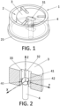
- Figure 1 shows a perspective view of a rotary pump 1 according to the invention.
- This rotary pump 1 comprises
- the rotor 3 rests on the chamber base 21, so that both surfaces are parallel and the gap between the rotor and the cover of the pump chamber is minimized.
- This rotor 3 is configured to rotate around a rotational axis Z orthogonal to the chamber base 21.
- the rotor 3 is directly laid on the driving element 4 which is in turn connected to a shaft (or is a part of the shaft), which transmits a rotational movement to the rotor.
- Figure 2 shows a perspective view in section to show the driving element 4 inside the rotor housing 31.
- the rotor housing 31 is a through hole.
- This figure shows a detail of the joint between the driving element 4 and the rotor housing 31, in a rotary pump 1 according to the invention.
- the driving element 4 comprises an external surface 40 which is intended to contact the rotor housing 31 in such a way that the rotor housing 31 can move over an external surface 40 of the driving element 4.
- this external surface 40 comprises a contact portion 41 which has the shape of part of a first sphere comprising an spherical zone.
- the external surface 40 also comprises two lateral (hemispherical) driving protrusions 42 which extend from the first sphere in a perpendicular direction from the rotation axis Z. These lateral driving protrusions 42 are arranged opposed to each other along a Y direction orthogonal to the rotational Z axis.
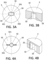
- Figures 3A and 3B show a perspective view and an elevation view of a detail of a configuration of the rotor housing 31 of the rotary pump of figure 1 .
- the rotor housing 31 comprises a central recess 32. This recess has substantially the same diameter as the first spherical zone of the contact portion 41, since the central recess 32 and the contact portion 41 are intended to couple.
- This rotor housing 31 further comprises two lateral cavities 33, each cavity 33 being intended to house one of the hemispherical lateral driving protrusions 42.
- the rotor housing 31 has a cross section in a plane orthogonal to axis Z comprising two arc shapes walls 321 defining part of a circumference to configure the central recess 32 and each of the lateral cavities 33 is defined between two vertical opposite walls 331 extending in a direction (Y) orthogonal to Z axis and a traverse end wall 332.
- the rotor housing 31 has a constant cross section as shown in figure 3B .
- This rotor housing 31 can house a driving element 4 as shown in figures 5A and 5B .
- Figures 4A and 4B show perspective view and an elevation view of a detail of another configuration of the rotor housing 31 of the rotary pump of figure 1 .
- This rotor housing 31 can house a driving element 4 as shown in figures 5D .
- Figures 5A, 5B , 5C and 5D show different configurations for the driving element 4.
- Figure 5A shows a driving element 4 comprising two driving protrusions 42 arranged opposed to each other along a direction orthogonal to axis Z, so that the protrusions protrude in a perpendicular direction from the rotation axis Z.
- the driving protrusions 42 are spherical shaped.
- the diameter of the spherical driving protrusion 42 is smaller than the diameter of first spherical zone of the contact portion 41.
- Figure 5B shows a driving element 4 comprising two driving protrusions 42 arranged in different planes perpendicular to axis Z.
- the driving protrusions 42 are spherical shaped.
- the diameter of the spherical driving protrusions 42 is smaller than the diameter of first spherical zone of the contact portion 41.
- Figure 5C shows a driving element 4 comprising two driving protrusions 42 arranged in a plane perpendicular to Z axis at an angle of 90°.
- the driving protrusions 42 are spherical shaped.
- the diameter of the spherical driving protrusion 42 is smaller than the diameter of first spherical zone of the contact portion 41.
- Figure 5D shows a driving element 4, which is not part of the present invention, comprising two driving protrusions 42 arranged opposed to each other along a direction orthogonal to axis Z, so that the protrusions protrude in a perpendicular direction from the rotation axis.
- the driving protrusions 42 are cylindrical shaped.
- Figures 6A, 6B and 6C show different views of the driving element 4 in angular deviation when the protrusions are spherical shaped and the central recess 32 as shown in figures 3A and 3B .
- Figure 6A corresponds to a side view in a plane orthogonal to Z axis when the driving element 4 rotates around Z axis.
- Figure 6B corresponds to a side view in a plane orthogonal to Y axis when the driver 4 has an angular deviation in this plane.
- Figure 6C corresponds to a side view in a plane orthogonal to X axis when the driver 4 has an angular deviation in this plane.
- Figures 7A, 7B and 7C show different views of the driving element 4, which are not part of the present invention, in angular deviation when the protrusions are cylindrical shaped and the central recess 32 as shown in figures 4A and 4B .
- Figure 7A corresponds to a side view in a plane orthogonal to Z axis when the driving element 4 rotates around Z axis.
- Figure 7B corresponds to a side view in a plane orthogonal to Y axis when the driver 4 has an angular deviation in this plane.
- Figure 7C corresponds to a side view in a plane orthogonal to X axis when the driver 4 has an angular deviation in this plane.
- Figures 8A and 8B are schematic representations of the housing of the rotor and a driver to show the dimensional relation of both elements, and specially the dimension L, I, H, h, e and A used in the formulas of the invention.
- Figure 8A represents a driving element (4) and rotor (3) with no misalignment and figure 8B shows an angular misalignment A between the driving element (4) and the rotor (3),
Landscapes
- Engineering & Computer Science (AREA)
- Mechanical Engineering (AREA)
- General Engineering & Computer Science (AREA)
- Details And Applications Of Rotary Liquid Pumps (AREA)
Claims (14)
- Pompe rotative (1) comprenant :une chambre de pompe (2) avec une base de chambre (21) ;un rotor (3) logé dans la chambre de pompe (2) et comprenant une base inférieure s'appuyant sur la base de chambre (21), le rotor (3) comprenant un boîtier de rotor (31) et configuré pour tourner autour d'un axe de rotation Z orthogonal à la base de chambre (21) ;un élément d'entraînement (4) prévu pour être logé dans le boîtier de rotor (31), l'élément d'entraînement (4) ayant une surface externe (40) comprenant :une partie de contact (41) comprenant une zone sphérique symétrique à l'axe Z ; etau moins une saillie d'entraînement latérale (42) fixée sur et s'étendant à partir de la zone sphérique le long d'une première direction (Y) orthogonale à l'axe Z, la au moins une saillie d'entraînement latérale (42) étant prévue pour transmettre un mouvement de rotation au rotor (3) autour de l'axe de rotation Z,et dans laquelle le boîtier de rotor (31) comprend :un évidement central (32) ayant un diamètre pour loger la partie de contact (41) ; etau moins une cavité latérale (33) prévue pour loger la au moins une saillie d'entraînement latérale (42),de sorte que la partie de contact (41) et l'évidement central (32) peuvent se mettre en prise de manière coulissante entre eux pour compenser les défauts d'alignement angulaires entre un axe orthogonal à la base inférieure du rotor (3) et l'axe Z, lorsque la base inférieure du rotor (3) s'appuie sur la base de chambre (21),et la au moins une cavité latérale (33) est configurée pour permettre un mouvement angulaire relatif, autour de n'importe quelle direction orthogonale à l'axe Z, entre la au moins une saillie d'entraînement latérale (42) et la au moins une cavité latérale (33) requise par le coulissement entre l'évidement central (32) et la partie de contact (41), pour maintenir la base inférieure du rotor (3) s'appuyant sur la base de chambre (21), mais mobile autour de l'axe Z par la poussée de la au moins une saillie d'entraînement latérale (42) contre la cavité latérale (33),caractérisée en ce que la au moins une saillie d'entraînement latérale (42) a la forme d'une hémisphère ou d'un segment sphérique.
- Pompe rotative (1) selon la revendication 1, dans laquelle le boîtier de rotor a une section transversale dans un plan orthogonal à l'axe Z comprenant deux parois en forme d'arc (321) définissant une partie d'une circonférence afin de configurer l'évidement central (32) et deux parois verticales (331) opposées s'étendant, à partir de l'évidement central, dans la première direction (Y) orthogonale à l'axe Z et une paroi d'extrémité transversale (332) dans une seconde direction (X) orthogonale à l'axe Z, afin de configurer la au moins une cavité latérale (33).
- Pompe rotative (1) selon la revendication 2, dans laquelle une section transversale de la zone sphérique de la partie de contact (41) a un diamètre D sensiblement égal au diamètre de la circonférence définie par les parois en forme d'arc (321) du boîtier de rotor.
- Pompe rotative selon l'une quelconque des revendications précédentes, dans laquelle une hauteur H de la au moins une cavité latérale (33), mesurée le long de la direction Z à partir de la base inférieure du rotor (3) est supérieure à (h + e/2), h étant une distance dans la direction Z entre la base inférieure du rotor (3) et un plan parallèle à la base inférieure et passant par le centre de la au moins une saillie d'entraînement latérale (42) et « e » étant une hauteur de la saillie d'entraînement latérale (42) mesurée dans la direction Z.
- Pompe rotative selon la revendication 4, dans laquelle la hauteur H le long de la direction Z de la au moins une cavité latérale (33) est supérieure ou égale à ((1 - e/2) sinA + e/2 + h)), « 1 » étant la longueur de la saillie d'entraînement latérale (42), et « A » étant le défaut d'alignement angulaire de l'élément d'entraînement (4) et/ou du rotor (3) autour d'un axe X orthogonal à un plan comprenant l'axe Z et la première direction (Y).
- Pompe rotative selon l'une quelconque des revendications précédentes, dans laquelle une longueur longitudinale « L » de la au moins une cavité latérale (33) le long de la première direction (Y) orthogonale à l'axe Z est supérieure à « 1 », « 1 » étant la longueur de la saillie d'entraînement latérale (42).
- Pompe rotative selon la revendication 6, dans laquelle la longueur longitudinale « L » de la au moins une cavité latérale (33) le long de la première direction (Y) orthogonale à l'axe Z est supérieure ou égale à (1 cosA + e/2 sinA), « e » étant la hauteur de la saillie d'entraînement latérale (42) mesurée dans la direction Z et « A » étant le défaut d'alignement angulaire de l'élément d'entraînement (4) et/ou du rotor (3) autour d'un axe X orthogonal à un plan comprenant l'axe Z et la première direction.
- Pompe rotative selon la revendication 6, dans laquelle la longueur longitudinale « L » de la au moins une cavité latérale (33) le long de la première direction (Y) orthogonale à l'axe Z est supérieure ou égale à ((1 - e/2) cos A + e/2)), « e » étant la hauteur de la saillie d'entraînement latérale (42) mesurée dans la direction Z et << A » étant le défaut d'alignement angulaire de l'élément d'entraînement (4) et/ou du rotor (3) autour d'un axe X orthogonal à un plan comprenant l'axe Z et la première direction.
- Pompe rotative selon l'une quelconque des revendications précédentes, dans laquelle l'élément d'entraînement (4) comprend deux saillies d'entraînement latérales (42).
- Pompe rotative selon la revendication 9, dans laquelle les deux saillies d'entraînement latérales (42) sont agencées à l'opposé l'une de l'autre le long de la première direction (Y) orthogonale à l'axe Z, de sorte que les saillies d'entraînement latérales (42) font saillie dans une direction perpendiculaire à partir de l'axe de rotation Z.
- Pompe rotative selon la revendication 9, dans laquelle les deux saillies d'entraînement latérales (42) sont agencées dans un plan perpendiculaire à l'axe Z à un angle inférieur à 180°.
- Pompe rotative selon l'une quelconque des revendications 9, 10 ou 11, dans laquelle les deux saillies d'entraînement latérales (42) sont agencées dans différents plans perpendiculaires à l'axe Z.
- Pompe rotative (1) selon l'une quelconque des revendications précédentes, dans laquelle l'élément d'entraînement (4) est un arbre.
- Pompe rotative (1) selon l'une quelconque des revendications précédentes, dans laquelle l'élément d'entraînement (4) comprend une partie intermédiaire s'étendant entre la partie de contact (41) et sa partie d'extrémité en forme de segment hémisphérique ou sphérique.
Priority Applications (4)
| Application Number | Priority Date | Filing Date | Title |
|---|---|---|---|
| EP18382236.0A EP3550148B1 (fr) | 2018-04-06 | 2018-04-06 | Pompe rotative |
| ES18382236T ES3000811T3 (en) | 2018-04-06 | 2018-04-06 | Rotary pump |
| CN201810734858.9A CN110345066A (zh) | 2018-04-06 | 2018-07-06 | 旋转泵 |
| PCT/EP2019/058571 WO2019193127A1 (fr) | 2018-04-06 | 2019-04-04 | Pompe rotative |
Applications Claiming Priority (1)
| Application Number | Priority Date | Filing Date | Title |
|---|---|---|---|
| EP18382236.0A EP3550148B1 (fr) | 2018-04-06 | 2018-04-06 | Pompe rotative |
Publications (3)
| Publication Number | Publication Date |
|---|---|
| EP3550148A1 EP3550148A1 (fr) | 2019-10-09 |
| EP3550148B1 true EP3550148B1 (fr) | 2024-10-30 |
| EP3550148C0 EP3550148C0 (fr) | 2024-10-30 |
Family
ID=62063474
Family Applications (1)
| Application Number | Title | Priority Date | Filing Date |
|---|---|---|---|
| EP18382236.0A Active EP3550148B1 (fr) | 2018-04-06 | 2018-04-06 | Pompe rotative |
Country Status (4)
| Country | Link |
|---|---|
| EP (1) | EP3550148B1 (fr) |
| CN (1) | CN110345066A (fr) |
| ES (1) | ES3000811T3 (fr) |
| WO (1) | WO2019193127A1 (fr) |
Families Citing this family (1)
| Publication number | Priority date | Publication date | Assignee | Title |
|---|---|---|---|---|
| NL2026544B1 (en) * | 2020-09-25 | 2022-05-30 | Dmn Machf Noordwykerhout B V | A rotary valve |
Citations (1)
| Publication number | Priority date | Publication date | Assignee | Title |
|---|---|---|---|---|
| DE102005020232A1 (de) * | 2004-05-07 | 2005-12-01 | Luk Fahrzeug-Hydraulik Gmbh & Co. Kg | Pumpe |
Family Cites Families (13)
| Publication number | Priority date | Publication date | Assignee | Title |
|---|---|---|---|---|
| US1526356A (en) * | 1922-02-06 | 1925-02-17 | American Cellulose And Chemica | Rotary pump |
| US1685815A (en) * | 1926-04-13 | 1928-10-02 | Irving C Jennings | Universal coupling |
| US3113527A (en) * | 1962-08-01 | 1963-12-10 | Ingersoll Rand Co | Pump or motor shaft and rotor coupling means |
| US3240156A (en) * | 1965-03-29 | 1966-03-15 | Hartley Ezra Dale | Rotary vane pump |
| FR2278011A1 (fr) * | 1974-07-11 | 1976-02-06 | Whittingham Ltd Geoffrey | Joint et transmission munie d'un tel joint |
| WO2000036303A1 (fr) * | 1998-12-14 | 2000-06-22 | Mitsubishi Denki Kabushiki Kaisha | Pompe a vide a ailettes pour automobiles |
| CN2389243Y (zh) * | 1999-09-24 | 2000-07-26 | 柳振新 | 梭阀转子泵 |
| FR2847315B1 (fr) * | 2002-11-14 | 2005-02-25 | Peugeot Citroen Automobiles Sa | Systeme de retenue en translation de deux pieces rotatives et procede de montage de ces deux pieces |
| CN101813085A (zh) * | 2010-03-22 | 2010-08-25 | 黄武源 | 自吸节能高效型水泵 |
| DE102010043118A1 (de) * | 2010-10-29 | 2012-05-03 | Robert Bosch Gmbh | Anordnung zur Übertragung eines Drehmoments zwischen einer Welle und einer Nabe |
| CN104813030A (zh) * | 2012-12-04 | 2015-07-29 | 麦格纳动力系巴德霍姆堡有限责任公司 | 电动机驱动的机动车真空泵和用于机动车真空泵的驱动轴 |
| DE102014220205A1 (de) * | 2014-10-07 | 2016-04-07 | Robert Bosch Gmbh | Pumpenanordnung mit Hauptpumpe und Hilfspumpe |
| CN106321671A (zh) * | 2015-06-18 | 2017-01-11 | 江苏荣基重工科技有限公司 | 可伸缩式万向节 |
-
2018
- 2018-04-06 ES ES18382236T patent/ES3000811T3/es active Active
- 2018-04-06 EP EP18382236.0A patent/EP3550148B1/fr active Active
- 2018-07-06 CN CN201810734858.9A patent/CN110345066A/zh active Pending
-
2019
- 2019-04-04 WO PCT/EP2019/058571 patent/WO2019193127A1/fr not_active Ceased
Patent Citations (1)
| Publication number | Priority date | Publication date | Assignee | Title |
|---|---|---|---|---|
| DE102005020232A1 (de) * | 2004-05-07 | 2005-12-01 | Luk Fahrzeug-Hydraulik Gmbh & Co. Kg | Pumpe |
Also Published As
| Publication number | Publication date |
|---|---|
| ES3000811T3 (en) | 2025-03-03 |
| EP3550148A1 (fr) | 2019-10-09 |
| CN110345066A (zh) | 2019-10-18 |
| WO2019193127A1 (fr) | 2019-10-10 |
| EP3550148C0 (fr) | 2024-10-30 |
Similar Documents
| Publication | Publication Date | Title |
|---|---|---|
| EP2759743B1 (fr) | Réducteur de vitesse | |
| EP2372188B1 (fr) | Transmission et procédé de fabrication | |
| CN110303518B (zh) | 关节部的构造 | |
| US8047943B2 (en) | Reduction gear transmission | |
| EP3296591B1 (fr) | Couronne et dispositif d'engrenage | |
| EP3270003B1 (fr) | Dispositif d'engrenage | |
| EP3550148B1 (fr) | Pompe rotative | |
| CN111981090A (zh) | 减速器 | |
| US10480619B2 (en) | Ring gear, gear device and mold for manufacturing the ring gear | |
| EP2543909B1 (fr) | Dispositif à engrenage | |
| KR101088633B1 (ko) | 기어드 모터 및 로봇용 기어드 모터 | |
| JP2005163804A (ja) | 回転軸継手 | |
| JP6546895B2 (ja) | ベーンポンプ | |
| US20220025959A1 (en) | Reduction gear | |
| US11111917B2 (en) | Internally rotating gear pump | |
| JP2003278784A (ja) | モータ | |
| CN110131362A (zh) | 摆线针轮减速器 | |
| CN211525441U (zh) | 一种少齿差两级减速器 | |
| US20090297255A1 (en) | Drive means | |
| CN115021486B (zh) | 一种舵机及航空发动机 | |
| KR20220122125A (ko) | 회전식 감속 액추에이터 | |
| CN220051899U (zh) | 机器人关节及机器人 | |
| CN117656000B (zh) | 一种用于上紧卷簧的浮动套筒传动装置及其使用方法 | |
| KR102944113B1 (ko) | 베벨 기어 및 하모닉 드라이브를 구비한 감속기를 갖는 수직 다관절 로봇 | |
| JPH0140334Y2 (fr) |
Legal Events
| Date | Code | Title | Description |
|---|---|---|---|
| PUAI | Public reference made under article 153(3) epc to a published international application that has entered the european phase |
Free format text: ORIGINAL CODE: 0009012 |
|
| STAA | Information on the status of an ep patent application or granted ep patent |
Free format text: STATUS: THE APPLICATION HAS BEEN PUBLISHED |
|
| AK | Designated contracting states |
Kind code of ref document: A1 Designated state(s): AL AT BE BG CH CY CZ DE DK EE ES FI FR GB GR HR HU IE IS IT LI LT LU LV MC MK MT NL NO PL PT RO RS SE SI SK SM TR |
|
| AX | Request for extension of the european patent |
Extension state: BA ME |
|
| STAA | Information on the status of an ep patent application or granted ep patent |
Free format text: STATUS: REQUEST FOR EXAMINATION WAS MADE |
|
| 17P | Request for examination filed |
Effective date: 20200408 |
|
| RBV | Designated contracting states (corrected) |
Designated state(s): AL AT BE BG CH CY CZ DE DK EE ES FI FR GB GR HR HU IE IS IT LI LT LU LV MC MK MT NL NO PL PT RO RS SE SI SK SM TR |
|
| STAA | Information on the status of an ep patent application or granted ep patent |
Free format text: STATUS: EXAMINATION IS IN PROGRESS |
|
| 17Q | First examination report despatched |
Effective date: 20220613 |
|
| GRAP | Despatch of communication of intention to grant a patent |
Free format text: ORIGINAL CODE: EPIDOSNIGR1 |
|
| STAA | Information on the status of an ep patent application or granted ep patent |
Free format text: STATUS: GRANT OF PATENT IS INTENDED |
|
| INTG | Intention to grant announced |
Effective date: 20240603 |
|
| GRAS | Grant fee paid |
Free format text: ORIGINAL CODE: EPIDOSNIGR3 |
|
| GRAA | (expected) grant |
Free format text: ORIGINAL CODE: 0009210 |
|
| STAA | Information on the status of an ep patent application or granted ep patent |
Free format text: STATUS: THE PATENT HAS BEEN GRANTED |
|
| AK | Designated contracting states |
Kind code of ref document: B1 Designated state(s): AL AT BE BG CH CY CZ DE DK EE ES FI FR GB GR HR HU IE IS IT LI LT LU LV MC MK MT NL NO PL PT RO RS SE SI SK SM TR |
|
| REG | Reference to a national code |
Ref country code: GB Ref legal event code: FG4D |
|
| REG | Reference to a national code |
Ref country code: CH Ref legal event code: EP |
|
| REG | Reference to a national code |
Ref country code: DE Ref legal event code: R096 Ref document number: 602018075929 Country of ref document: DE |
|
| REG | Reference to a national code |
Ref country code: IE Ref legal event code: FG4D |
|
| U01 | Request for unitary effect filed |
Effective date: 20241129 |
|
| U07 | Unitary effect registered |
Designated state(s): AT BE BG DE DK EE FI FR IT LT LU LV MT NL PT RO SE SI Effective date: 20241205 |
|
| REG | Reference to a national code |
Ref country code: ES Ref legal event code: FG2A Ref document number: 3000811 Country of ref document: ES Kind code of ref document: T3 Effective date: 20250303 |
|
| PG25 | Lapsed in a contracting state [announced via postgrant information from national office to epo] |
Ref country code: IS Free format text: LAPSE BECAUSE OF FAILURE TO SUBMIT A TRANSLATION OF THE DESCRIPTION OR TO PAY THE FEE WITHIN THE PRESCRIBED TIME-LIMIT Effective date: 20250228 Ref country code: HR Free format text: LAPSE BECAUSE OF FAILURE TO SUBMIT A TRANSLATION OF THE DESCRIPTION OR TO PAY THE FEE WITHIN THE PRESCRIBED TIME-LIMIT Effective date: 20241030 |
|
| PG25 | Lapsed in a contracting state [announced via postgrant information from national office to epo] |
Ref country code: NO Free format text: LAPSE BECAUSE OF FAILURE TO SUBMIT A TRANSLATION OF THE DESCRIPTION OR TO PAY THE FEE WITHIN THE PRESCRIBED TIME-LIMIT Effective date: 20250130 |
|
| PG25 | Lapsed in a contracting state [announced via postgrant information from national office to epo] |
Ref country code: PL Free format text: LAPSE BECAUSE OF FAILURE TO SUBMIT A TRANSLATION OF THE DESCRIPTION OR TO PAY THE FEE WITHIN THE PRESCRIBED TIME-LIMIT Effective date: 20241030 |
|
| PG25 | Lapsed in a contracting state [announced via postgrant information from national office to epo] |
Ref country code: RS Free format text: LAPSE BECAUSE OF FAILURE TO SUBMIT A TRANSLATION OF THE DESCRIPTION OR TO PAY THE FEE WITHIN THE PRESCRIBED TIME-LIMIT Effective date: 20250130 |
|
| U20 | Renewal fee for the european patent with unitary effect paid |
Year of fee payment: 8 Effective date: 20250324 |
|
| PG25 | Lapsed in a contracting state [announced via postgrant information from national office to epo] |
Ref country code: SM Free format text: LAPSE BECAUSE OF FAILURE TO SUBMIT A TRANSLATION OF THE DESCRIPTION OR TO PAY THE FEE WITHIN THE PRESCRIBED TIME-LIMIT Effective date: 20241030 |
|
| PGFP | Annual fee paid to national office [announced via postgrant information from national office to epo] |
Ref country code: ES Payment date: 20250501 Year of fee payment: 8 |
|
| PG25 | Lapsed in a contracting state [announced via postgrant information from national office to epo] |
Ref country code: SK Free format text: LAPSE BECAUSE OF FAILURE TO SUBMIT A TRANSLATION OF THE DESCRIPTION OR TO PAY THE FEE WITHIN THE PRESCRIBED TIME-LIMIT Effective date: 20241030 |
|
| PG25 | Lapsed in a contracting state [announced via postgrant information from national office to epo] |
Ref country code: CZ Free format text: LAPSE BECAUSE OF FAILURE TO SUBMIT A TRANSLATION OF THE DESCRIPTION OR TO PAY THE FEE WITHIN THE PRESCRIBED TIME-LIMIT Effective date: 20241030 |
|
| PLBE | No opposition filed within time limit |
Free format text: ORIGINAL CODE: 0009261 |
|
| STAA | Information on the status of an ep patent application or granted ep patent |
Free format text: STATUS: NO OPPOSITION FILED WITHIN TIME LIMIT |
|
| 26N | No opposition filed |
Effective date: 20250731 |
|
| REG | Reference to a national code |
Ref country code: CH Ref legal event code: H13 Free format text: ST27 STATUS EVENT CODE: U-0-0-H10-H13 (AS PROVIDED BY THE NATIONAL OFFICE) Effective date: 20251125 |
|
| PG25 | Lapsed in a contracting state [announced via postgrant information from national office to epo] |
Ref country code: MC Free format text: LAPSE BECAUSE OF FAILURE TO SUBMIT A TRANSLATION OF THE DESCRIPTION OR TO PAY THE FEE WITHIN THE PRESCRIBED TIME-LIMIT Effective date: 20241030 |
|
| GBPC | Gb: european patent ceased through non-payment of renewal fee |
Effective date: 20250406 |
|
| PG25 | Lapsed in a contracting state [announced via postgrant information from national office to epo] |
Ref country code: GB Free format text: LAPSE BECAUSE OF NON-PAYMENT OF DUE FEES Effective date: 20250406 |
|
| PG25 | Lapsed in a contracting state [announced via postgrant information from national office to epo] |
Ref country code: CH Free format text: LAPSE BECAUSE OF NON-PAYMENT OF DUE FEES Effective date: 20250430 |
|
| PG25 | Lapsed in a contracting state [announced via postgrant information from national office to epo] |
Ref country code: IE Free format text: LAPSE BECAUSE OF NON-PAYMENT OF DUE FEES Effective date: 20250406 |