EP3550147A1 - Verdichtersystem - Google Patents
Verdichtersystem Download PDFInfo
- Publication number
- EP3550147A1 EP3550147A1 EP19167376.3A EP19167376A EP3550147A1 EP 3550147 A1 EP3550147 A1 EP 3550147A1 EP 19167376 A EP19167376 A EP 19167376A EP 3550147 A1 EP3550147 A1 EP 3550147A1
- Authority
- EP
- European Patent Office
- Prior art keywords
- end portion
- suction port
- peripheral surface
- insertion end
- abutment region
- Prior art date
- Legal status (The legal status is an assumption and is not a legal conclusion. Google has not performed a legal analysis and makes no representation as to the accuracy of the status listed.)
- Granted
Links
Images
Classifications
-
- F—MECHANICAL ENGINEERING; LIGHTING; HEATING; WEAPONS; BLASTING
- F04—POSITIVE - DISPLACEMENT MACHINES FOR LIQUIDS; PUMPS FOR LIQUIDS OR ELASTIC FLUIDS
- F04C—ROTARY-PISTON, OR OSCILLATING-PISTON, POSITIVE-DISPLACEMENT MACHINES FOR LIQUIDS; ROTARY-PISTON, OR OSCILLATING-PISTON, POSITIVE-DISPLACEMENT PUMPS
- F04C29/00—Component parts, details or accessories of pumps or pumping installations, not provided for in groups F04C18/00 - F04C28/00
- F04C29/12—Arrangements for admission or discharge of the working fluid, e.g. constructional features of the inlet or outlet
-
- F—MECHANICAL ENGINEERING; LIGHTING; HEATING; WEAPONS; BLASTING
- F04—POSITIVE - DISPLACEMENT MACHINES FOR LIQUIDS; PUMPS FOR LIQUIDS OR ELASTIC FLUIDS
- F04C—ROTARY-PISTON, OR OSCILLATING-PISTON, POSITIVE-DISPLACEMENT MACHINES FOR LIQUIDS; ROTARY-PISTON, OR OSCILLATING-PISTON, POSITIVE-DISPLACEMENT PUMPS
- F04C18/00—Rotary-piston pumps specially adapted for elastic fluids
- F04C18/30—Rotary-piston pumps specially adapted for elastic fluids having the characteristics covered by two or more of groups F04C18/02, F04C18/08, F04C18/22, F04C18/24, F04C18/48, or having the characteristics covered by one of these groups together with some other type of movement between co-operating members
- F04C18/34—Rotary-piston pumps specially adapted for elastic fluids having the characteristics covered by two or more of groups F04C18/02, F04C18/08, F04C18/22, F04C18/24, F04C18/48, or having the characteristics covered by one of these groups together with some other type of movement between co-operating members having the movement defined in group F04C18/08 or F04C18/22 and relative reciprocation between the co-operating members
- F04C18/356—Rotary-piston pumps specially adapted for elastic fluids having the characteristics covered by two or more of groups F04C18/02, F04C18/08, F04C18/22, F04C18/24, F04C18/48, or having the characteristics covered by one of these groups together with some other type of movement between co-operating members having the movement defined in group F04C18/08 or F04C18/22 and relative reciprocation between the co-operating members with vanes reciprocating with respect to the outer member
-
- F—MECHANICAL ENGINEERING; LIGHTING; HEATING; WEAPONS; BLASTING
- F04—POSITIVE - DISPLACEMENT MACHINES FOR LIQUIDS; PUMPS FOR LIQUIDS OR ELASTIC FLUIDS
- F04C—ROTARY-PISTON, OR OSCILLATING-PISTON, POSITIVE-DISPLACEMENT MACHINES FOR LIQUIDS; ROTARY-PISTON, OR OSCILLATING-PISTON, POSITIVE-DISPLACEMENT PUMPS
- F04C23/00—Combinations of two or more pumps, each being of rotary-piston or oscillating-piston type, specially adapted for elastic fluids; Pumping installations specially adapted for elastic fluids; Multi-stage pumps specially adapted for elastic fluids
- F04C23/001—Combinations of two or more pumps, each being of rotary-piston or oscillating-piston type, specially adapted for elastic fluids; Pumping installations specially adapted for elastic fluids; Multi-stage pumps specially adapted for elastic fluids of similar working principle
-
- F—MECHANICAL ENGINEERING; LIGHTING; HEATING; WEAPONS; BLASTING
- F04—POSITIVE - DISPLACEMENT MACHINES FOR LIQUIDS; PUMPS FOR LIQUIDS OR ELASTIC FLUIDS
- F04C—ROTARY-PISTON, OR OSCILLATING-PISTON, POSITIVE-DISPLACEMENT MACHINES FOR LIQUIDS; ROTARY-PISTON, OR OSCILLATING-PISTON, POSITIVE-DISPLACEMENT PUMPS
- F04C23/00—Combinations of two or more pumps, each being of rotary-piston or oscillating-piston type, specially adapted for elastic fluids; Pumping installations specially adapted for elastic fluids; Multi-stage pumps specially adapted for elastic fluids
- F04C23/008—Hermetic pumps
-
- F—MECHANICAL ENGINEERING; LIGHTING; HEATING; WEAPONS; BLASTING
- F04—POSITIVE - DISPLACEMENT MACHINES FOR LIQUIDS; PUMPS FOR LIQUIDS OR ELASTIC FLUIDS
- F04C—ROTARY-PISTON, OR OSCILLATING-PISTON, POSITIVE-DISPLACEMENT MACHINES FOR LIQUIDS; ROTARY-PISTON, OR OSCILLATING-PISTON, POSITIVE-DISPLACEMENT PUMPS
- F04C2240/00—Components
- F04C2240/80—Other components
- F04C2240/804—Accumulators for refrigerant circuits
-
- F—MECHANICAL ENGINEERING; LIGHTING; HEATING; WEAPONS; BLASTING
- F04—POSITIVE - DISPLACEMENT MACHINES FOR LIQUIDS; PUMPS FOR LIQUIDS OR ELASTIC FLUIDS
- F04C—ROTARY-PISTON, OR OSCILLATING-PISTON, POSITIVE-DISPLACEMENT MACHINES FOR LIQUIDS; ROTARY-PISTON, OR OSCILLATING-PISTON, POSITIVE-DISPLACEMENT PUMPS
- F04C2240/00—Components
- F04C2240/80—Other components
- F04C2240/806—Pipes for fluids; Fittings therefor
Definitions
- the present invention relates to a compressor system.
- a device used for compressing a refrigerant in an air conditioner a device equipped with an accumulator and a compressor is known (see PTL 1 below).
- the accumulator performs a gas-liquid separation of the refrigerant prior to introduction to the compressor.
- the compressor and the accumulator are connected to each other by a suction pipe.
- the compressor compresses only the vapor-phase refrigerant supplied from the accumulator through the suction pipe to generate a high-pressure gas-phase refrigerant.
- the compressor includes a compression mechanism unit which has a suction port for sucking in the refrigerant, a cylinder in which a compression chamber for compressing the sucked in refrigerant and a piston rotor rotating eccentrically in the cylinder are formed, and a housing that accommodates the compression mechanism unit.
- the high-pressure refrigerant generated in the compression chamber is discharged outside via a space inside the housing.
- the suction pipe extends from the accumulator located outside the housing to a suction port in the housing.
- the high-pressure refrigerant generated in the compression chamber circulates in the space inside the housing.
- the refrigerant has a higher temperature than the refrigerant before compression. Therefore, in the above configuration, there is a possibility that the heat of the high-pressure refrigerant will propagate to the refrigerant flowing through the suction pipe before compression. As a result, the efficiency of the compressor will decrease.
- the present invention has been made to solve the aforementioned problems, and an object of the present invention is to provide a compressor system in which the efficiency of the compressor is able to be improved, while the suction pipe is reliably fixed to the suction port.
- a compressor system including a crankshaft that is configured to rotate about an axis; a compression mechanism unit which includes a piston rotor that is configured to rotate eccentrically with rotation of the crankshaft, and a cylinder having a compression chamber accommodating the piston rotor formed inside; a housing which accommodates the crankshaft and the compression mechanism unit and through which a high-pressure refrigerant generated by the compression mechanism unit flows; an accumulator in which the refrigerant is stored; and a suction pipe in which an insertion end portion to be inserted into an suction port formed in the cylinder is formed at an end portion and which supplies the refrigerant before compression from the accumulator to the compression chamber.
- an abutment region in which the outer peripheral surface of the insertion end portion and the inner peripheral surface of the suction port abut each other, and a non-abutment region forming a space between the outer peripheral surface of the insertion end portion and the inner peripheral surface of the suction port are formed.
- a space is formed between the outer peripheral surface of the insertion end portion and the inner peripheral surface of the suction port.
- the inside of the housing and the inside of the suction pipe are separated from each other by the space. Therefore, it can be made difficult for the heat of the high-temperature and high-pressure refrigerant flowing through the housing to be transmitted to the refrigerant before compression flowing through the suction pipe. As a result, it is possible to minimize a temperature rise of the refrigerant before compression.
- the outer peripheral surface of the insertion end portion abuts against the inner peripheral surface of the suction port. Accordingly, even when an external force is applied to the suction port or the insertion end portion due to the vibration of the suction pipe, it is possible to sufficiently resist the external force. Therefore, the insertion end portion can be firmly fixed to the suction port.
- the non-abutment region may be formed at least on one side in an axial line direction in which the axial line extends with respect to the insertion end portion.
- the non-abutment region A2 is formed in a portion in which the temperature easily rises. Therefore, it can be made difficult for the heat of the high-temperature and high-pressure refrigerant in the housing to be transmitted to the refrigerant in the suction pipe.
- the non-abutment region may be formed on both sides in the axial line direction with respect to the insertion end portion.
- the abutment region may be formed on both sides in a horizontal direction orthogonal to the axial line direction in which the axial line extends with respect to the insertion end portion.
- the insertion end portion in the abutment region, may abut the inner peripheral surface of the suction port in an elastically deformed state.
- the outer peripheral surface of the insertion end portion and the inner peripheral surface of the suction port are strongly brought into contact with each other by the restoring force caused by the elastic deformation. Therefore, the insertion end portion can be more firmly fixed to the suction port.
- the suction pipe may have a suction pipe main body which abuts the inner peripheral surface of the suction port over the entire circumference, and a connecting portion which connects the suction pipe main body and the insertion end portion, and a suction pipe end surface, which is an end surface of the insertion end portion, may abut a suction port bottom surface facing the suction pipe end surface in the suction port.
- a space independent from the outside is formed by the outer peripheral surface of the insertion end portion, the suction port end surface, the inner peripheral surface of the suction port, and the outer peripheral surface of the connecting portion. That is, it is possible to form a space thermally independent from the outside, and to more effectively minimize heat transfer between the inside of the housing and the inside of the suction pipe.
- the suction port may have a circular cross section
- the insertion end portion may have an elliptical cross section
- an end edge in a major axis direction of the ellipse may form the abutment region
- an end edge in a minor axis direction may form the non-abutment region.
- the insertion end portion may have a circular cross section
- the suction port may have an elliptical cross section
- an end edge in the major axis direction of the ellipse may form the abutment region
- an end edge in the minor axis direction may form the non-abutment region.
- FIGS. 1 to 4 A first embodiment of the present invention will be described with reference to FIGS. 1 to 4 . It should be noted that the expression “same” in the following description refers to substantially the same, and for example, design tolerance and manufacturing error are acceptable.
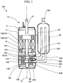
- a compressor system 100 includes an accumulator 24, suction pipes 26A and 26B (a first suction pipe 26A and a second suction pipe 26B), and a compressor 10.
- the compressor 10 according to the present embodiment is a two-cylinder type rotary compressor.
- the compressor 10 includes a motor 18 driven by an external power source, a compression mechanism unit 10A that compresses a refrigerant (fluid) by being driven with the motor 18 such that it generates a high-pressure refrigerant, and a housing 11 which covers the motor 18 and the compression mechanism unit 10A.
- the compression mechanism unit 10A includes a crankshaft 16 rotated by the motor 18, piston rotors 13A and 13B (a first piston rotor 13A and a second piston rotor 13B) which rotate eccentrically with rotation of the crankshaft 16, and cylinders 12A and 12B (a first cylinder 12A and a second cylinder 12B) in which compression chambers for accommodating the piston rotors 13A and 13B are formed inside.
- the disk-shaped first cylinder 12A and the disk-shaped second cylinder 12B are provided inside the cylindrical housing 11 in two stages in a vertical direction.
- the housing 11 surrounds the first cylinder 12A and the second cylinder 12B, thereby forming a discharge space V through which the compressed refrigerant is discharged.
- a cylindrical first piston rotor 13A and a second piston rotor 13B having an outer shape smaller than the inner side of its inner wall surface are disposed inside the first cylinder 12A and the second cylinder 12B, respectively.
- the first piston rotor 13A and the second piston rotor 13B are inserted and fixed to eccentric shaft portions 14A and 14B of the rotation axis along the center axial line of the housing 11, respectively.
- the first piston rotor 13A of the cylinder of the upper stage side, and the second piston rotor 13B of the lower stage side are provided so that their phases differ from each other by 180°. Further, a disc-shaped partition plate 15 is provided between the upper first cylinder 12A and the lower second cylinder 12B.
- the space R in the first cylinder 12A on the upper stage side and the space R in the second cylinder 12B on the lower stage side are divided into the compression chamber R1 and the lower stage compression chamber R2 by the partition plate 15 and do not communicate with each other.
- the crankshaft 16 is supported to be rotatable around an axial line O by an upper bearing portion 17A fixed to the first cylinder 12A and a lower bearing portion 17B fixed to the second cylinder 12B.
- the crankshaft 16 has eccentric shaft portions 14A and 14B that are offset in a direction orthogonal to the axial line O which is a center line of the crankshaft 16. As the eccentric shaft portions 14A and 14B turn about the central axial line of the crankshaft 16, the upper first piston rotors 13A and the lower second piston rotors 13B follow the turning and eccentrically rotate inside the first cylinder 12A and the second cylinder 12B.
- the crankshaft 16 protrudes upward from the upper bearing portion 17A (that is, a direction in which the motor 18 is located as viewed from the compression mechanism unit 10A).
- a rotor 19A of a motor 18 for rotationally driving the crankshaft 16 is integrally provided in a portion protruding upward from the upper bearing portion 17A of the crankshaft 16.
- a stator 19B is provided by being fixed to the inner peripheral surface of the housing 11 to face the outer peripheral portion of the rotor 19A.
- an accumulator 24 for performing gas-liquid separation of refrigerant prior to supplying to the compressor 10 is fixed to the housing 11 via a stay 25.
- the refrigerant before compression is stored in the accumulator 24.
- a first suction pipe 26A and a second suction pipe 26B for sucking the refrigerant in the accumulator 24 into the compressor 10 are provided between the accumulator 24 and the compressor 10.
- One ends of the first suction pipe 26A and the second suction pipe 26B are connected to the lower portion of the accumulator 24.
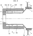
- first suction pipe 26A and the second suction pipe 26B are connected to the suction ports 23A and 23B (the first suction port 23A and the second suction port 23B) formed in each of the first cylinder 12Aand the second cylinder 12B through the openings 22A and 22B (a first opening 22A and a second opening 22B) formed in the housing 11.
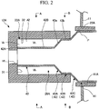
- first suction port 23A and the second suction port 23B and the first suction pipe 26A and the second suction pipe 26B will be described with reference to FIGS. 2 to 4 . Since the connection mode of the first suction port 23A and the first suction pipe 26A is the same as the connection mode of the second suction port 23B and the second suction pipe 26B, in the following description, only the first suction port 23A and the first suction pipe 26A will be representatively described.
- the first suction port 23A is recessed radially inward from a surface facing radially outwards centered on the axial line O of the first cylinder 12A.
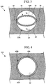
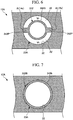
- the first suction port 23A has a circular cross section when viewed from the radial direction (see FIG. 3 or FIG. 4 ).
- a surface facing the radially outer side inside the first suction port 23A serves as a suction port bottom surface 31.
- the inner peripheral surface of the first suction port 23A is the suction port inner peripheral surface 32.
- a space surrounded by the suction port bottom surface 31 and the suction port inner peripheral surface 32 is an insertion space Vs into which the first suction pipe 26A is inserted.
- a communicating hole H1 through which the insertion space Vs and the aforementioned compression chamber R1 communicate with each other is formed on the suction port bottom surface 31.
- the first suction pipe 26A has a suction pipe main body 41, an insertion end portion 42, and a connecting portion 43.
- An insertion end portion 42 that forms an end portion on one side of the first suction pipe 26A is inserted into the insertion space Vs in the first suction port 23A.
- the insertion end portion 42 has an elliptical cross section when viewed from the radial direction. More specifically, the insertion end portion 42 is inserted into the first suction port 23A to make a minor axis direction of the ellipse coincident with the direction of the axial line O (a vertical direction) extending the axial line O.
- a distal end surface of the insertion end portion 42 (that is, an end surface of the insertion end portion 42 facing the communicating hole H1) is a suction pipe end surface 42A.
- the suction pipe end surface 42A abuts against the above-described suction port bottom surface 31.
- An inner diameter (a length in a minor axis direction) of the insertion end portion 42 is larger than a diameter of the communicating hole HI.
- the insertion end portion 42 is connected to the suction pipe main body 41 via the connecting portion 43 on a side opposite to the suction pipe end surface 42A. More specifically, the connecting portion 43 has a first connecting portion 43A, an extending portion 43B, and a second connecting portion 43C.
- the first connecting portion 43A is connected to the other side of the insertion end portion 42 (the suction pipe main body 41 side with respect to the insertion end portion 42).
- the extending portion 43B is connected to the other side of the first connecting portion 43A.
- the extending portion 43B has a circular cross section when viewed from the radial direction. A diameter of the extending portion 43B is substantially equal to a length of the first connecting portion 43A in a major axis direction.
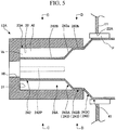
- the cross-sectional shape of the first connecting portion 43A gradually changes from an elliptical shape to a circular shape, from the insertion end portion 42 side to the suction pipe main body 41 side. More specifically, in the first connecting portion 43A, the length of the elliptical shape in the minor axis direction gradually increases from the insertion end portion 42 side toward the suction pipe main body 41 side to coincide with the dimension of the elliptical shape in the major axis direction. As illustrated in FIG. 4 , the outer peripheral surface (an extending portion outer peripheral surface 43b) of the extending portion 43B abuts the suction port inner peripheral surface 32 over the entire circumference.
- the second connecting portion 43C is connected to the other side of the extending portion 43B.
- the second connecting portion 43C connects the extending portion 43B and the suction pipe main body 41.
- the diameter dimension of the suction pipe main body 41 is larger than the diameter dimension of the extending portion 43B. That is, the second connecting portion 43C gradually expands in diameter from the insertion end portion 42 side to the suction pipe main body 41 side.
- the suction pipe main body 41 extends toward the accumulator 24 through a first opening 22A formed in the housing 11. Further, as illustrated in FIG. 2 , an annular guide tube P fixed in a state of being inserted through the first opening 22A is attached to the first opening 22A to cover an end edge of the first opening 22A.
- an abutment region A1 and a non-abutment region A2 are formed between the outer peripheral surface (the insertion end portion outer peripheral surface 42B) of the insertion end portion 42 and the suction port inner peripheral surface 32.
- the insertion end portion outer peripheral surface 42B and the suction port inner peripheral surface 32 abut each other. More specifically, the insertion end portion outer peripheral surface 42B forming the end portions on both sides in the major axis direction of the insertion end portion 42 having an elliptical cross section abuts the suction port inner peripheral surface 32, thereby forming an abutment region A1.
- the abutment region A1 of the present embodiment is formed on both sides in the horizontal direction orthogonal to the direction of the axial line O with respect to the insertion end portion 42.
- the insertion end portion 42 abuts against the suction port inner peripheral surface 32 in a state of being slightly elastically deformed inward in the major axis direction.
- a space is formed between the insertion end portion outer peripheral surface 42B and the suction port inner peripheral surface 32.
- This space is a part of the insertion space Vs and is referred to as a heat insulation space Vh. That is, since the insertion end portion outer peripheral surface 42B and the suction port inner peripheral surface 32 forming the end portions on both sides of the insertion end portion 42 having an elliptical cross section in the short axis direction are separated from each other, the non-abutment region A2 is formed.
- the heat insulation space Vh is a space defined by the suction port bottom surface 31, the suction port inner peripheral surface 32, the outer peripheral surface (a first connecting portion outer peripheral surface 43a) of the first connecting portion 43A, and the insertion end portion outer peripheral surface 42B.
- the heat insulation space Vh is formed on both sides of the insertion end portion 42 in the direction of the axial line O across the abutment region A1.
- the motor 18 is driven first by power supply from the outside.
- the compressor 10 takes the refrigerant into the accumulator 24 from the suction port 24a of the accumulator 24. Specifically, the refrigerant is separated into a liquid phase component and a gas phase component in the accumulator 24.
- the separated gas phase components are supplied from the first suction pipe 26A and the second suction pipe 26B to the compression chambers R1 and R2 as the internal spaces of the first cylinder 12A and the second cylinder 12B via the first suction port 23A and the second suction port 23B.
- the volumes of the compression chambers R1 and R2 gradually decrease and the refrigerant is compressed.
- the refrigerant passes through the vicinity of the motor 18 in the housing 11 and the periphery of the first suction port 23A and the second suction port 23B, and then is discharged to a piping 27 constituting the refrigeration cycle via the discharge port provided in the upper portion.
- the refrigerant discharged from the compression chambers R1 and R2 is heated to a high temperature with the compression in addition to having a high pressure.
- the high-temperature and high-pressure refrigerant passes around the first suction port 23A and the second suction port 23B when flowing through the housing 11 as described above.
- the refrigerant before compression that is, low-temperature and low-pressure refrigerant compared with the compressed refrigerant flows through the inside of the first suction port 23A and the second suction port 23B, and the inside of the first suction pipe 26A and the second suction pipe 26B inserted therein.
- the abutment region A1 and the non-abutment region A2 are formed between the insertion end portion 42 of the first suction pipe 26A and the first suction port 23A.
- a heat insulation space Vh is formed between the insertion end portion outer peripheral surface 42B and the suction port inner peripheral surface 32.
- the inside of the housing 11 and the inside of the first suction pipe 26A are separated from each other by the heat insulation space Vh. Therefore, it can be made difficult for the heat of the high-temperature and high-pressure refrigerant flowing through the housing 11 to be transmitted to the refrigerant before compression flowing through the first suction pipe 26A. As a result, it is possible to minimize a temperature rise of the refrigerant before compression.
- the insertion end portion outer peripheral surface 42B abuts the suction port inner peripheral surface 32. Accordingly, even when an external force is applied to the first suction port 23A or the insertion end portion 42 due to the vibration of the first suction pipe 26A caused by pulsation or the like of the inflowing refrigerant, it is possible to sufficiently resist the external force. Therefore, the insertion end portion 42 can be firmly fixed to the first suction port 23A. Thus, it is possible to improve the efficiency of the compressor 10, while the first suction pipe 26A is reliably fixed to the first suction port 23A.
- the temperature easily rises due to the high-temperature and high-pressure refrigerant in the housing 11.
- the non-abutment region A2 is formed in a portion in which the temperature easily rises. Therefore, the heat of the high-temperature and high-pressure refrigerant in the housing 11 can be made hard to be transmitted by the refrigerant in the first suction pipe 26A.
- the insertion end portion outer peripheral surface 42B abuts the suction port inner peripheral surface 32 in the elastically deformed state, the insertion end portion outer peripheral surface 42B and the suction port inner peripheral surface 32 strongly come into contact each other by the restoring force due to the elastic deformation. Therefore, the insertion end portion 42 can be more firmly fixed to the first suction port 23A.
- the extending portion 43B connected to the insertion end portion 42 abuts the suction port inner peripheral surface 32 over the entire circumference. Further, the end surface (the suction pipe end surface 42A) of the insertion end portion 42 abuts against the suction port bottom surface 31. Therefore, in the non-abutment region A2, a space independent from the outside is formed by the insertion end portion outer peripheral surface 42B, the suction port bottom surface 31, the suction port inner peripheral surface 32, and the outer peripheral surface of the first connecting portion 43A (the first connecting portion outer peripheral surface 43a), and the space can be the above-described heat insulation space Vh. That is, the heat insulation space Vh can be a space thermally independent from the outside. As a result, it is possible to more effectively suppress the heat transfer between the inside of the housing 11 and the inside of the first suction pipe 26A.
- the first suction port 23A has a circular cross section
- the insertion end portion 42 has an elliptical cross section. That is, the abutment region A1 and the non-abutment region A2 can be easily formed only by setting the insertion end portion 42 to have an elliptical cross section. As a result, the time and cost required for processing can be reduced.
- connection mode between the first suction port 23A and the first suction pipe 26A, and the connection mode between the second suction port 23B and the second suction pipe 26B are identical to each other, the first suction port 23A and the first suction pipe 26A has been described, and the function and effect thereof has been described with reference to only these configurations.
- the second suction port 23B and the second suction pipe 26B can also obtain the same configuration and the same operation and effect on the basis thereof.
- FIGS. 5 to 7 A modified example of the first embodiment of the present invention will be described with reference to FIGS. 5 to 7 .
- the same configurations as those of the first embodiment are denoted by the same reference numerals, and the detailed explanation thereof will not be provided.
- the connection mode between the first suction port 23A and the first suction pipe 26A and the connection mode between the second suction port 23B and the second suction pipe 26B are identical to each other, the configuration of the first suction port 23A and the first suction pipe 26A will be representatively described.
- the cross sectional shape of the insertion end portion 242 of the first suction pipe 26A is different from that of the first embodiment.
- the insertion end portion 242 has a circular cross section smaller than the suction pipe main body 41 and has a pair of protruding portions 242P protruding from the insertion end portion outer peripheral surface 242B toward the suction port inner peripheral surface 32.
- the pair of protruding portions 242P extends in a direction (a horizontal direction) orthogonal to the axial line O from the insertion end portion outer peripheral surface 242B.
- the distal end surface Pa (that is, the end surface facing the suction port inner peripheral surface 32) of the protruding portion 242P is curved to conform to the curved shape of the suction port inner peripheral surface 32, the distal end surface Pa abuts against the suction port inner peripheral surface 32 without a gap. That is, between the suction port inner peripheral surface 32 and the insertion end portion outer peripheral surface 242B, the protruding portion 242P forms the abutment region A1. Further, as illustrated in FIG. 5 , the protruding portion 242P extends from the suction pipe end surface 242A to the boundary position between the connecting portion 243 and the insertion end portion 242 in the extending direction of the insertion end portion 242.
- the connecting portion 243 is integrally connected to a suction pipe main body 41 having a circular cross section. More specifically, similarly to the first embodiment, the connecting portion 243 has a first connecting portion 243A, an extending portion 243B, and a second connecting portion 243C.
- the first connecting portion 243A is connected to the other side of the insertion end portion 242.
- the extending portion 243B is connected to the other side of the first connecting portion 243A.
- the extending portion 243B has a circular cross section when viewed from the radial direction.
- the outer peripheral surface (the extending portion outer peripheral surface 243b) of the extending portion 243B abuts the suction port inner peripheral surface 32 over the entire circumference.
- the second connecting portion 243C connects the extending portion 243B and the suction pipe main body 41.
- the non-abutment region A2 In the non-abutment region A2, the protruding portion 242P, the insertion end portion outer peripheral surface 242B, the suction port inner peripheral surface 32, and the first connecting portion outer peripheral surface 243a form the above-described heat insulation space Vh.
- FIGS. 8 and 9 a second embodiment of the present invention will be described with reference to FIGS. 8 and 9 .
- the same components as those of the first embodiment are denoted by the same reference numerals, and a detailed description thereof will not be provided.
- the connection mode between the first suction port 23A and the first suction pipe 26A, and the connection mode between the second suction port 23B and the second suction pipe 26B are identical to each other, the configuration of the first suction port 23A and the first suction pipe 26A will be representatively described.
- the insertion end portion 342 is connected to the suction pipe main body 41 via the connecting portion 343.
- the insertion end portion 342 has a circular cross section smaller than the suction pipe main body 41.
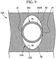
- the suction port 323A has an elliptical cross section and is recessed.
- the inner peripheral surface (the suction port inner peripheral surface 332) forming the end portion in the major axis direction of the elliptical shape abuts the insertion end portion outer peripheral surface 342B to form the abutment region A1.
- the suction port inner peripheral surface 332 forming the end portion in the minor axis direction forms the non-abutment region A2 by forming the heat insulation space Vh between the suction port inner peripheral surface 332 and the insertion end portion outer peripheral surface 342B.
- the insertion end portion 342 has a circular cross section
- the suction port 323A has an elliptical cross section. That is, the abutment region A1 and the non-abutment region A2 can be easily formed only by forming the suction port 323A into an elliptical cross section. As a result, the time and cost required for processing can be reduced.
Landscapes
- Engineering & Computer Science (AREA)
- Mechanical Engineering (AREA)
- General Engineering & Computer Science (AREA)
- Applications Or Details Of Rotary Compressors (AREA)
Applications Claiming Priority (1)
| Application Number | Priority Date | Filing Date | Title |
|---|---|---|---|
| JP2018074090A JP2019183720A (ja) | 2018-04-06 | 2018-04-06 | 圧縮機システム |
Publications (3)
| Publication Number | Publication Date |
|---|---|
| EP3550147A1 true EP3550147A1 (de) | 2019-10-09 |
| EP3550147C0 EP3550147C0 (de) | 2023-07-05 |
| EP3550147B1 EP3550147B1 (de) | 2023-07-05 |
Family
ID=66092228
Family Applications (1)
| Application Number | Title | Priority Date | Filing Date |
|---|---|---|---|
| EP19167376.3A Active EP3550147B1 (de) | 2018-04-06 | 2019-04-04 | Verdichtersystem |
Country Status (2)
| Country | Link |
|---|---|
| EP (1) | EP3550147B1 (de) |
| JP (1) | JP2019183720A (de) |
Cited By (3)
| Publication number | Priority date | Publication date | Assignee | Title |
|---|---|---|---|---|
| CN111536044A (zh) * | 2020-05-20 | 2020-08-14 | 珠海凌达压缩机有限公司 | 压缩机进气组件、压缩机以及空调 |
| US20220186731A1 (en) * | 2019-09-04 | 2022-06-16 | Samsung Electronics Co., Ltd. | Rotary compressor and home appliance including same |
| CN116771645A (zh) * | 2022-03-11 | 2023-09-19 | 上海海立电器有限公司 | 一种进气组件及压缩机 |
Citations (5)
| Publication number | Priority date | Publication date | Assignee | Title |
|---|---|---|---|---|
| US4639198A (en) * | 1984-11-13 | 1987-01-27 | Tecumseh Products Company | Suction tube seal for a rotary compressor |
| JPH05312152A (ja) * | 1992-05-12 | 1993-11-22 | Daikin Ind Ltd | 圧縮機における配管接続装置 |
| JP2004285993A (ja) * | 2003-03-25 | 2004-10-14 | Matsushita Electric Ind Co Ltd | 密閉型圧縮機 |
| EP2778421A1 (de) * | 2011-11-08 | 2014-09-17 | Panasonic Corporation | Verdichter |
| JP2014190267A (ja) | 2013-03-27 | 2014-10-06 | Mitsubishi Electric Corp | 回転圧縮機 |
-
2018
- 2018-04-06 JP JP2018074090A patent/JP2019183720A/ja active Pending
-
2019
- 2019-04-04 EP EP19167376.3A patent/EP3550147B1/de active Active
Patent Citations (5)
| Publication number | Priority date | Publication date | Assignee | Title |
|---|---|---|---|---|
| US4639198A (en) * | 1984-11-13 | 1987-01-27 | Tecumseh Products Company | Suction tube seal for a rotary compressor |
| JPH05312152A (ja) * | 1992-05-12 | 1993-11-22 | Daikin Ind Ltd | 圧縮機における配管接続装置 |
| JP2004285993A (ja) * | 2003-03-25 | 2004-10-14 | Matsushita Electric Ind Co Ltd | 密閉型圧縮機 |
| EP2778421A1 (de) * | 2011-11-08 | 2014-09-17 | Panasonic Corporation | Verdichter |
| JP2014190267A (ja) | 2013-03-27 | 2014-10-06 | Mitsubishi Electric Corp | 回転圧縮機 |
Cited By (4)
| Publication number | Priority date | Publication date | Assignee | Title |
|---|---|---|---|---|
| US20220186731A1 (en) * | 2019-09-04 | 2022-06-16 | Samsung Electronics Co., Ltd. | Rotary compressor and home appliance including same |
| US12000401B2 (en) * | 2019-09-04 | 2024-06-04 | Samsung Electronics Co., Ltd. | Rotary compressor with first and second main suction ports |
| CN111536044A (zh) * | 2020-05-20 | 2020-08-14 | 珠海凌达压缩机有限公司 | 压缩机进气组件、压缩机以及空调 |
| CN116771645A (zh) * | 2022-03-11 | 2023-09-19 | 上海海立电器有限公司 | 一种进气组件及压缩机 |
Also Published As
| Publication number | Publication date |
|---|---|
| JP2019183720A (ja) | 2019-10-24 |
| EP3550147C0 (de) | 2023-07-05 |
| EP3550147B1 (de) | 2023-07-05 |
Similar Documents
| Publication | Publication Date | Title |
|---|---|---|
| CN104204531B (zh) | 气体压缩机 | |
| EP3550147B1 (de) | Verdichtersystem | |
| WO2013145713A1 (ja) | 圧縮機 | |
| US20100322796A1 (en) | Hermetic compressor | |
| JP2006009792A (ja) | 回転式圧縮機 | |
| KR101667710B1 (ko) | 로터리 압축기 | |
| JP2015183611A (ja) | ベーン型圧縮機 | |
| US10533554B2 (en) | Cylinder-rotation compressor with improved vane and suction passage locations | |
| JP2019183721A (ja) | 圧縮機システム | |
| JP2010121481A (ja) | ロータリ圧縮機 | |
| US10125770B2 (en) | Cylinder-rotation compressor with a discharge valve | |
| WO2015025449A1 (ja) | 多段圧縮機及び冷凍サイクル装置 | |
| CN104819154A (zh) | 密闭型压缩机 | |
| EP4008906A1 (de) | Rotationsverdichter | |
| EP3141754B1 (de) | Drehkompressor und verfahren zur herstellung davon | |
| EP3550146B1 (de) | Verdichtersystem | |
| JP2009167976A (ja) | 回転式流体機械 | |
| WO2019021976A1 (ja) | ロータリ圧縮機 | |
| JP7697492B2 (ja) | ロータリ圧縮機 | |
| JP6596787B2 (ja) | スクロール圧縮機 | |
| JP2007113489A (ja) | 回転式圧縮機 | |
| JP6374737B2 (ja) | シリンダ回転型圧縮機 | |
| EP3557067B1 (de) | Kolbenrotor, kurbelwelle, rotationsverdichter und verfahren zur montage der kurbelwelle | |
| CN111868384B (zh) | 多级压缩机 | |
| JP2020193567A (ja) | ロータリ圧縮機 |
Legal Events
| Date | Code | Title | Description |
|---|---|---|---|
| PUAI | Public reference made under article 153(3) epc to a published international application that has entered the european phase |
Free format text: ORIGINAL CODE: 0009012 |
|
| STAA | Information on the status of an ep patent application or granted ep patent |
Free format text: STATUS: THE APPLICATION HAS BEEN PUBLISHED |
|
| AK | Designated contracting states |
Kind code of ref document: A1 Designated state(s): AL AT BE BG CH CY CZ DE DK EE ES FI FR GB GR HR HU IE IS IT LI LT LU LV MC MK MT NL NO PL PT RO RS SE SI SK SM TR |
|
| AX | Request for extension of the european patent |
Extension state: BA ME |
|
| STAA | Information on the status of an ep patent application or granted ep patent |
Free format text: STATUS: REQUEST FOR EXAMINATION WAS MADE |
|
| 17P | Request for examination filed |
Effective date: 20200409 |
|
| RBV | Designated contracting states (corrected) |
Designated state(s): AL AT BE BG CH CY CZ DE DK EE ES FI FR GB GR HR HU IE IS IT LI LT LU LV MC MK MT NL NO PL PT RO RS SE SI SK SM TR |
|
| STAA | Information on the status of an ep patent application or granted ep patent |
Free format text: STATUS: EXAMINATION IS IN PROGRESS |
|
| 17Q | First examination report despatched |
Effective date: 20220307 |
|
| GRAP | Despatch of communication of intention to grant a patent |
Free format text: ORIGINAL CODE: EPIDOSNIGR1 |
|
| STAA | Information on the status of an ep patent application or granted ep patent |
Free format text: STATUS: GRANT OF PATENT IS INTENDED |
|
| INTG | Intention to grant announced |
Effective date: 20230120 |
|
| GRAS | Grant fee paid |
Free format text: ORIGINAL CODE: EPIDOSNIGR3 |
|
| GRAA | (expected) grant |
Free format text: ORIGINAL CODE: 0009210 |
|
| STAA | Information on the status of an ep patent application or granted ep patent |
Free format text: STATUS: THE PATENT HAS BEEN GRANTED |
|
| AK | Designated contracting states |
Kind code of ref document: B1 Designated state(s): AL AT BE BG CH CY CZ DE DK EE ES FI FR GB GR HR HU IE IS IT LI LT LU LV MC MK MT NL NO PL PT RO RS SE SI SK SM TR |
|
| REG | Reference to a national code |
Ref country code: CH Ref legal event code: EP |
|
| REG | Reference to a national code |
Ref country code: AT Ref legal event code: REF Ref document number: 1585080 Country of ref document: AT Kind code of ref document: T Effective date: 20230715 |
|
| REG | Reference to a national code |
Ref country code: DE Ref legal event code: R096 Ref document number: 602019031968 Country of ref document: DE |
|
| REG | Reference to a national code |
Ref country code: IE Ref legal event code: FG4D |
|
| U01 | Request for unitary effect filed |
Effective date: 20230705 |
|
| RAP4 | Party data changed (patent owner data changed or rights of a patent transferred) |
Owner name: MITSUBISHI HEAVY INDUSTRIES THERMAL SYSTEMS, LTD. |
|
| U07 | Unitary effect registered |
Designated state(s): AT BE BG DE DK EE FI FR IT LT LU LV MT NL PT SE SI Effective date: 20230728 |
|
| REG | Reference to a national code |
Ref country code: LT Ref legal event code: MG9D |
|
| PG25 | Lapsed in a contracting state [announced via postgrant information from national office to epo] |
Ref country code: GR Free format text: LAPSE BECAUSE OF FAILURE TO SUBMIT A TRANSLATION OF THE DESCRIPTION OR TO PAY THE FEE WITHIN THE PRESCRIBED TIME-LIMIT Effective date: 20231006 |
|
| PG25 | Lapsed in a contracting state [announced via postgrant information from national office to epo] |
Ref country code: ES Free format text: LAPSE BECAUSE OF FAILURE TO SUBMIT A TRANSLATION OF THE DESCRIPTION OR TO PAY THE FEE WITHIN THE PRESCRIBED TIME-LIMIT Effective date: 20230705 |
|
| PG25 | Lapsed in a contracting state [announced via postgrant information from national office to epo] |
Ref country code: IS Free format text: LAPSE BECAUSE OF FAILURE TO SUBMIT A TRANSLATION OF THE DESCRIPTION OR TO PAY THE FEE WITHIN THE PRESCRIBED TIME-LIMIT Effective date: 20231105 |
|
| PG25 | Lapsed in a contracting state [announced via postgrant information from national office to epo] |
Ref country code: RS Free format text: LAPSE BECAUSE OF FAILURE TO SUBMIT A TRANSLATION OF THE DESCRIPTION OR TO PAY THE FEE WITHIN THE PRESCRIBED TIME-LIMIT Effective date: 20230705 Ref country code: NO Free format text: LAPSE BECAUSE OF FAILURE TO SUBMIT A TRANSLATION OF THE DESCRIPTION OR TO PAY THE FEE WITHIN THE PRESCRIBED TIME-LIMIT Effective date: 20231005 Ref country code: IS Free format text: LAPSE BECAUSE OF FAILURE TO SUBMIT A TRANSLATION OF THE DESCRIPTION OR TO PAY THE FEE WITHIN THE PRESCRIBED TIME-LIMIT Effective date: 20231105 Ref country code: HR Free format text: LAPSE BECAUSE OF FAILURE TO SUBMIT A TRANSLATION OF THE DESCRIPTION OR TO PAY THE FEE WITHIN THE PRESCRIBED TIME-LIMIT Effective date: 20230705 Ref country code: GR Free format text: LAPSE BECAUSE OF FAILURE TO SUBMIT A TRANSLATION OF THE DESCRIPTION OR TO PAY THE FEE WITHIN THE PRESCRIBED TIME-LIMIT Effective date: 20231006 Ref country code: ES Free format text: LAPSE BECAUSE OF FAILURE TO SUBMIT A TRANSLATION OF THE DESCRIPTION OR TO PAY THE FEE WITHIN THE PRESCRIBED TIME-LIMIT Effective date: 20230705 |
|
| PG25 | Lapsed in a contracting state [announced via postgrant information from national office to epo] |
Ref country code: PL Free format text: LAPSE BECAUSE OF FAILURE TO SUBMIT A TRANSLATION OF THE DESCRIPTION OR TO PAY THE FEE WITHIN THE PRESCRIBED TIME-LIMIT Effective date: 20230705 |
|
| REG | Reference to a national code |
Ref country code: DE Ref legal event code: R097 Ref document number: 602019031968 Country of ref document: DE |
|
| U20 | Renewal fee for the european patent with unitary effect paid |
Year of fee payment: 6 Effective date: 20240306 |
|
| PG25 | Lapsed in a contracting state [announced via postgrant information from national office to epo] |
Ref country code: SM Free format text: LAPSE BECAUSE OF FAILURE TO SUBMIT A TRANSLATION OF THE DESCRIPTION OR TO PAY THE FEE WITHIN THE PRESCRIBED TIME-LIMIT Effective date: 20230705 Ref country code: RO Free format text: LAPSE BECAUSE OF FAILURE TO SUBMIT A TRANSLATION OF THE DESCRIPTION OR TO PAY THE FEE WITHIN THE PRESCRIBED TIME-LIMIT Effective date: 20230705 Ref country code: CZ Free format text: LAPSE BECAUSE OF FAILURE TO SUBMIT A TRANSLATION OF THE DESCRIPTION OR TO PAY THE FEE WITHIN THE PRESCRIBED TIME-LIMIT Effective date: 20230705 Ref country code: SK Free format text: LAPSE BECAUSE OF FAILURE TO SUBMIT A TRANSLATION OF THE DESCRIPTION OR TO PAY THE FEE WITHIN THE PRESCRIBED TIME-LIMIT Effective date: 20230705 |
|
| PLBE | No opposition filed within time limit |
Free format text: ORIGINAL CODE: 0009261 |
|
| STAA | Information on the status of an ep patent application or granted ep patent |
Free format text: STATUS: NO OPPOSITION FILED WITHIN TIME LIMIT |
|
| 26N | No opposition filed |
Effective date: 20240408 |
|
| PG25 | Lapsed in a contracting state [announced via postgrant information from national office to epo] |
Ref country code: MC Free format text: LAPSE BECAUSE OF FAILURE TO SUBMIT A TRANSLATION OF THE DESCRIPTION OR TO PAY THE FEE WITHIN THE PRESCRIBED TIME-LIMIT Effective date: 20230705 |
|
| PG25 | Lapsed in a contracting state [announced via postgrant information from national office to epo] |
Ref country code: MC Free format text: LAPSE BECAUSE OF FAILURE TO SUBMIT A TRANSLATION OF THE DESCRIPTION OR TO PAY THE FEE WITHIN THE PRESCRIBED TIME-LIMIT Effective date: 20230705 |
|
| REG | Reference to a national code |
Ref country code: CH Ref legal event code: PL |
|
| PG25 | Lapsed in a contracting state [announced via postgrant information from national office to epo] |
Ref country code: CH Free format text: LAPSE BECAUSE OF NON-PAYMENT OF DUE FEES Effective date: 20240430 |
|
| U20 | Renewal fee for the european patent with unitary effect paid |
Year of fee payment: 7 Effective date: 20250310 |
|
| PG25 | Lapsed in a contracting state [announced via postgrant information from national office to epo] |
Ref country code: IE Free format text: LAPSE BECAUSE OF NON-PAYMENT OF DUE FEES Effective date: 20240404 |
|
| PG25 | Lapsed in a contracting state [announced via postgrant information from national office to epo] |
Ref country code: CY Free format text: LAPSE BECAUSE OF FAILURE TO SUBMIT A TRANSLATION OF THE DESCRIPTION OR TO PAY THE FEE WITHIN THE PRESCRIBED TIME-LIMIT; INVALID AB INITIO Effective date: 20190404 |
|
| PG25 | Lapsed in a contracting state [announced via postgrant information from national office to epo] |
Ref country code: HU Free format text: LAPSE BECAUSE OF FAILURE TO SUBMIT A TRANSLATION OF THE DESCRIPTION OR TO PAY THE FEE WITHIN THE PRESCRIBED TIME-LIMIT; INVALID AB INITIO Effective date: 20190404 |
|
| PG25 | Lapsed in a contracting state [announced via postgrant information from national office to epo] |
Ref country code: TR Free format text: LAPSE BECAUSE OF FAILURE TO SUBMIT A TRANSLATION OF THE DESCRIPTION OR TO PAY THE FEE WITHIN THE PRESCRIBED TIME-LIMIT Effective date: 20230705 |
|
| PGFP | Annual fee paid to national office [announced via postgrant information from national office to epo] |
Ref country code: GB Payment date: 20260313 Year of fee payment: 8 |
|
| U20 | Renewal fee for the european patent with unitary effect paid |
Year of fee payment: 8 Effective date: 20260310 |