EP3550146B1 - Verdichtersystem - Google Patents
Verdichtersystem Download PDFInfo
- Publication number
- EP3550146B1 EP3550146B1 EP19167139.5A EP19167139A EP3550146B1 EP 3550146 B1 EP3550146 B1 EP 3550146B1 EP 19167139 A EP19167139 A EP 19167139A EP 3550146 B1 EP3550146 B1 EP 3550146B1
- Authority
- EP
- European Patent Office
- Prior art keywords
- diameter portion
- guide pipe
- suction pipe
- suction
- pipe
- Prior art date
- Legal status (The legal status is an assumption and is not a legal conclusion. Google has not performed a legal analysis and makes no representation as to the accuracy of the status listed.)
- Active
Links
Images


Classifications
-
- F—MECHANICAL ENGINEERING; LIGHTING; HEATING; WEAPONS; BLASTING
- F04—POSITIVE - DISPLACEMENT MACHINES FOR LIQUIDS; PUMPS FOR LIQUIDS OR ELASTIC FLUIDS
- F04C—ROTARY-PISTON, OR OSCILLATING-PISTON, POSITIVE-DISPLACEMENT MACHINES FOR LIQUIDS; ROTARY-PISTON, OR OSCILLATING-PISTON, POSITIVE-DISPLACEMENT PUMPS
- F04C18/00—Rotary-piston pumps specially adapted for elastic fluids
- F04C18/30—Rotary-piston pumps specially adapted for elastic fluids having the characteristics covered by two or more of groups F04C18/02, F04C18/08, F04C18/22, F04C18/24, F04C18/48, or having the characteristics covered by one of these groups together with some other type of movement between co-operating members
- F04C18/34—Rotary-piston pumps specially adapted for elastic fluids having the characteristics covered by two or more of groups F04C18/02, F04C18/08, F04C18/22, F04C18/24, F04C18/48, or having the characteristics covered by one of these groups together with some other type of movement between co-operating members having the movement defined in group F04C18/08 or F04C18/22 and relative reciprocation between the co-operating members
- F04C18/356—Rotary-piston pumps specially adapted for elastic fluids having the characteristics covered by two or more of groups F04C18/02, F04C18/08, F04C18/22, F04C18/24, F04C18/48, or having the characteristics covered by one of these groups together with some other type of movement between co-operating members having the movement defined in group F04C18/08 or F04C18/22 and relative reciprocation between the co-operating members with vanes reciprocating with respect to the outer member
-
- F—MECHANICAL ENGINEERING; LIGHTING; HEATING; WEAPONS; BLASTING
- F04—POSITIVE - DISPLACEMENT MACHINES FOR LIQUIDS; PUMPS FOR LIQUIDS OR ELASTIC FLUIDS
- F04C—ROTARY-PISTON, OR OSCILLATING-PISTON, POSITIVE-DISPLACEMENT MACHINES FOR LIQUIDS; ROTARY-PISTON, OR OSCILLATING-PISTON, POSITIVE-DISPLACEMENT PUMPS
- F04C23/00—Combinations of two or more pumps, each being of rotary-piston or oscillating-piston type, specially adapted for elastic fluids; Pumping installations specially adapted for elastic fluids; Multi-stage pumps specially adapted for elastic fluids
- F04C23/001—Combinations of two or more pumps, each being of rotary-piston or oscillating-piston type, specially adapted for elastic fluids; Pumping installations specially adapted for elastic fluids; Multi-stage pumps specially adapted for elastic fluids of similar working principle
-
- F—MECHANICAL ENGINEERING; LIGHTING; HEATING; WEAPONS; BLASTING
- F04—POSITIVE - DISPLACEMENT MACHINES FOR LIQUIDS; PUMPS FOR LIQUIDS OR ELASTIC FLUIDS
- F04C—ROTARY-PISTON, OR OSCILLATING-PISTON, POSITIVE-DISPLACEMENT MACHINES FOR LIQUIDS; ROTARY-PISTON, OR OSCILLATING-PISTON, POSITIVE-DISPLACEMENT PUMPS
- F04C23/00—Combinations of two or more pumps, each being of rotary-piston or oscillating-piston type, specially adapted for elastic fluids; Pumping installations specially adapted for elastic fluids; Multi-stage pumps specially adapted for elastic fluids
- F04C23/008—Hermetic pumps
-
- F—MECHANICAL ENGINEERING; LIGHTING; HEATING; WEAPONS; BLASTING
- F04—POSITIVE - DISPLACEMENT MACHINES FOR LIQUIDS; PUMPS FOR LIQUIDS OR ELASTIC FLUIDS
- F04C—ROTARY-PISTON, OR OSCILLATING-PISTON, POSITIVE-DISPLACEMENT MACHINES FOR LIQUIDS; ROTARY-PISTON, OR OSCILLATING-PISTON, POSITIVE-DISPLACEMENT PUMPS
- F04C29/00—Component parts, details or accessories of pumps or pumping installations, not provided for in groups F04C18/00 - F04C28/00
- F04C29/12—Arrangements for admission or discharge of the working fluid, e.g. constructional features of the inlet or outlet
-
- F—MECHANICAL ENGINEERING; LIGHTING; HEATING; WEAPONS; BLASTING
- F04—POSITIVE - DISPLACEMENT MACHINES FOR LIQUIDS; PUMPS FOR LIQUIDS OR ELASTIC FLUIDS
- F04C—ROTARY-PISTON, OR OSCILLATING-PISTON, POSITIVE-DISPLACEMENT MACHINES FOR LIQUIDS; ROTARY-PISTON, OR OSCILLATING-PISTON, POSITIVE-DISPLACEMENT PUMPS
- F04C2240/00—Components
- F04C2240/80—Other components
- F04C2240/804—Accumulators for refrigerant circuits
-
- F—MECHANICAL ENGINEERING; LIGHTING; HEATING; WEAPONS; BLASTING
- F04—POSITIVE - DISPLACEMENT MACHINES FOR LIQUIDS; PUMPS FOR LIQUIDS OR ELASTIC FLUIDS
- F04C—ROTARY-PISTON, OR OSCILLATING-PISTON, POSITIVE-DISPLACEMENT MACHINES FOR LIQUIDS; ROTARY-PISTON, OR OSCILLATING-PISTON, POSITIVE-DISPLACEMENT PUMPS
- F04C2240/00—Components
- F04C2240/80—Other components
- F04C2240/806—Pipes for fluids; Fittings therefor
Definitions
- the present invention relates to a compressor system.
- an apparatus including an accumulator and a compressor is known as an apparatus used for compression of refrigerant in an air conditioning apparatus.
- the accumulator separates the refrigerant into a gas phase and a liquid phase prior to introduction to the compressor.
- the compressor and the accumulator are connected by a suction pipe.
- the compressor compresses only a gas phase refrigerant supplied from the accumulator through the suction pipe and generates a high pressure gas phase refrigerant.
- a compressor disclosed in PTL 1 includes an electrically driven element accommodated in a closed case, and a compression element including a cylinder.
- An intake pipe communicates with an intake hole of the cylinder. Further, an opening through which the intake pipe is inserted is formed in the closed case.
- a guide pipe configured to cover the intake pipe on an outer circumferential side is attached to an edge of the opening formed in the closed case.
- a large diameter section and a small diameter section are formed in each of the guide pipe and the intake pipe, and the large diameter section of the intake pipe is joined to the large diameter section of the guide pipe.
- the cylinder is fixed to an inner circumferential surface of the closed case. That is, the intake hole communicates with the opening formed in the inner circumferential surface of the closed case with no gaps therebetween.
- a cylinder in a compressor, a cylinder may be pressed by an intake pipe when the intake pipe is inserted into an intake hole (an intake port) of the cylinder, and a position of the cylinder in a housing may be shifted.
- the cylinder is not directly fixed into the housing in a structure supported and fixed into the housing by a bearing apparatus instead of a structure in which the cylinder is fixed to an inner circumferential surface of the housing (a closed case) as described above.
- a position of the cylinder readily shifts in comparison with the case in which the cylinder is directly fixed into the housing. When an axial center position of the cylinder shifts, this may have an influence on an operation of the compressor.
- the present invention is directed to providing a compressor system having a compressor that can be more stably operated, without exerting an influence on the position of a cylinder.
- a compressor system includes a crankshaft that is configured to rotate around an axis thereof; a compression mechanism unit having a piston rotor that is configured to rotate eccentrically with rotation of the crankshaft and having a cylinder in which a compression chamber accommodating the piston rotor formed inside; a housing which accommodating the crankshaft and the compression mechanism unit and through which a high pressure refrigerant generated by the compression mechanism unit flows; a guide pipe disposed coaxially with a suction port formed in the cylinder and fixed while being inserted into an opening formed in the housing; an accumulator in which the refrigerant is stored; and a suction pipe inserted through the guide pipe and the suction port and configured to supply the refrigerant before compression from the accumulator to the compression chamber, wherein an end portion of the suction port on the suction pipe side is provided at a position away from an inner surface of the housing, the guide pipe has: a guide pipe small diameter portion formed at a position close to the suction port;
- the outer circumferential surface of the suction pipe large diameter portion abuts the inner circumferential surface of the guide pipe large diameter portion. That is, when the guide pipe large diameter portion is provided, the suction pipe is not pushed toward the inner circumferential side more than the guide pipe large diameter portion. As a result, the cylinder can be prevented from being pushed and moved by the end portion of the suction pipe.
- an angle formed between the outer circumferential surface of the suction pipe widening diameter portion and a direction in which the suction pipe small diameter portion extends may be larger than an angle between the inner circumferential surface of the guide pipe widening diameter portion and a direction in which the guide pipe small diameter portion extends.
- an angle formed between the outer circumferential surface of the suction pipe widening diameter portion and a direction in which the suction pipe small diameter portion extends may be smaller than an angle formed between the inner circumferential surface of the guide pipe widening diameter portion and a direction in which the guide pipe small diameter portion extends.
- the inner circumferential surface of the guide pipe widening diameter portion and the outer circumferential surface of the suction pipe widening diameter portion can securely come in contact with each other. Accordingly, sealability between the first suction pipe and the first guide pipe can be further improved.
- the compressor system may include a pair of compression mechanism units disposed in an axial direction in which the axis extends; a pair of guide pipes fixed to a pair of openings formed in the housing at positions separated from each other in the axial direction; and a pair of suction pipes inserted through the guide pipes and inserted through the suction ports formed in the cylinder.
- the diameter dimension of the opening can be equal to the outer diameter dimension of the guide pipe small diameter portion. That is, the diameter dimension of the opening can be made as small as. As a result, a large distance between edges of the pair of openings in the housing can be secured. Accordingly, since the pressure resistance of the housing can be improved, the pressure of the refrigerant flowing through the housing can be increased.
- a compressor system can be more stably operated without exerting an influence on the position of a cylinder.
- FIG. 1 to FIG. 3 An embodiment of the present invention will be described with reference to FIG. 1 to FIG. 3 .
- the expression "the same” in the following description indicates substantially the same, and allows, for example, a tolerance in design or manufacturing error.
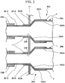
- a compressor system 100 includes an accumulator 24, suction pipes 26A and 26B (a first suction pipe 26A, a second suction pipe 26B), guide pipes 30A and 30B (a first guide pipe 30A, a second guide pipe 30B), and a compressor 10.
- the compressor 10 according to the embodiment is a 2-cylinder type rotary compressor.
- the compressor 10 includes a motor 18 driven by an external power supply, a compression mechanism unit 10A driven by the motor 18 to compress a refrigerant and generate a high pressure refrigerant, and a housing 11 configured to cover the motor 18 and the compression mechanism unit 10A.
- the compression mechanism unit 10A includes a crankshaft 16 rotated by the motor 18, piston rotors 13A and 13B (a first piston rotor 13A, a second piston rotor 13B) eccentrically rotated according to rotation of the crankshaft 16, and cylinders 12A and 12B (a first cylinder 12A, a second cylinder 12B) in which compression chambers configured to accommodate the piston rotors 13A and 13B are formed.
- the first cylinder 12A and the second cylinder 12B having a disk shape are provided in two stages in a vertical direction in the housing 11 having a cylindrical shape.
- the housing 11 surrounds the first cylinder 12A and the second cylinder 12B and forms a discharge space V from which a compressed refrigerant is discharged.
- the first piston rotor 13A and the second piston rotor 13B each having a cylindrical shape with an external form smaller than an inside between the inner wall surfaces are disposed in the first cylinder 12A and the second cylinder 12B.
- the first piston rotor 13A and the second piston rotor 13B are inserted and fixed to eccentric shaft portions 14A and 14B of a rotary shaft along a central axis of the housing 11.
- the first piston rotor 13A of the cylinder on an upper stage side and the second piston rotor 13B on a lower stage side are provided such that phases thereof are different from each other by 180°.
- a disk-shaped partition plate 15 is provided between the first cylinder 12A and the second cylinder 12B, which are above and below each other.
- a space R in the first cylinder 12A on an upper stage side and a space R in the second cylinder 12B on a lower stage side are partitioned into a compression chamber R1 on an upper stage side and a compression chamber R2 on a lower stage side by the partition plate 15 with no communication therebetween.
- the first cylinder 12A is fixed into the housing 11 by an upper bearing portion 17A.
- the second cylinder 12B is fixed into the housing 11 by a lower bearing portion 17B.
- the upper bearing portion 17A is formed in a disk shape fixed to an upper section of the first cylinder 12A.
- An outer circumferential surface of the upper bearing portion 17A is fixed to an inner circumferential surface of the housing 11.
- the lower bearing portion 17B is formed in a disk shape fixed to a lower section of the second cylinder 12B.
- An outer circumferential surface of the second cylinder 12B is fixed to an inner circumferential surface of the housing 11. That is, the first cylinder 12A and the second cylinder 12B are indirectly fixed into the housing 11 via the upper bearing portion 17A and the lower bearing portion 17B instead of being directly fixed into the housing 11.
- the crankshaft 16 is supported rotatably about an axis O by the upper bearing portion 17A fixed to the first cylinder 12A and the lower bearing portion 17B fixed to the second cylinder 12B.
- the crankshaft 16 has the eccentric shaft portions 14A and 14B offset in a direction perpendicular to the axis O that is a centerline of the crankshaft 16.
- the crankshaft 16 protrudes upward from the upper bearing portion 17A (i.e., a direction in which the motor 18 is disposed when seen from the compression mechanism unit 10A).
- a rotor 19A of the motor 18 configured to rotate the crankshaft 16 is provided integrally with a portion of the crankshaft 16 protruding upward from the upper bearing portion 17A.
- a stator 19B faces an outer circumferential section of the rotor 19A and is provided to be fixed to the inner circumferential surface of the housing 11.
- the accumulator 24 that separates a refrigerant into a gas phase and a liquid phase prior to supply to the compressor 10 is fixed into the housing 11 via a stay 25.
- a refrigerant before compression is stored in the accumulator 24.
- the first suction pipe 26A and the second suction pipe 26B configured to suction the refrigerant in the accumulator 24 into the compressor 10 are provided between the accumulator 24 and the compressor 10.
- One ends of the first suction pipe 26A and the second suction pipe 26B are connected to the lower section of the accumulator 24.
- first suction pipe 26A and the second suction pipe 26B are connected to suction ports 23A and 23B (a first suction port 23A, a second suction port 23B) formed in the first cylinder 12A and the second cylinder 12B through openings 22A and 22B (a first opening 22A and a second opening 22B) formed in the housing 11.
- the first guide pipe 30A is fixed in a state in which the first guide pipe 30A is inserted through the first opening 22A formed in the housing 11.
- the first guide pipe 30A is disposed coaxially with the first suction port such that positions in an axis O direction overlap each other.
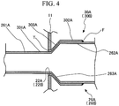
- the first guide pipe 30A has a guide pipe small diameter portion 301A, a guide pipe large diameter portion 302A and a guide pipe widening diameter portion 303A.
- the guide pipe small diameter portion 301A is formed at a side of the first guide pipe 30A closest to the first suction port 23A.
- the guide pipe small diameter portion 301A is fixed into the housing 11 while being inserted through the first opening 22A. That is, the inner diameter of the first opening 22A is equal to the guide pipe small diameter portion 301A.
- Part of the guide pipe small diameter portion 301A protrudes in the housing 11. Further, a tip portion T (an end portion of a side separated from an inner surface of the housing 11) of the guide pipe small diameter portion 301A faces the first suction port 23A with a gap therebetween.
- the guide pipe large diameter portion 302A extends coaxially with the guide pipe small diameter portion 301A and has a diameter larger than that of the guide pipe small diameter portion 301A.
- the guide pipe widening diameter portion 303A connects the guide pipe small diameter portion 301A and the guide pipe large diameter portion 302A. That is, the guide pipe widening diameter portion 303A has a diameter that gradually increases from the guide pipe small diameter portion 301A side toward the guide pipe large diameter portion 302A. Further, all of the guide pipe small diameter portion 301A, the guide pipe large diameter portion 302A and the guide pipe widening diameter portion 303A have a circular cross section.
- the first suction pipe 26A extends in the housing 11 and is inserted into the first suction port 23A while being inserted through the first guide pipe 30A.
- the first suction pipe 26A has a suction pipe small diameter portion 261A, a suction pipe large diameter portion 262A and a suction pipe widening diameter portion 263A.
- the suction pipe small diameter portion 261A is inserted through the guide pipe small diameter portion 301A.
- the suction pipe large diameter portion 262A is inserted through the guide pipe large diameter portion 302A.
- the suction pipe large diameter portion 262A has a diameter dimension larger than that of the suction pipe small diameter portion 261A.
- the suction pipe widening diameter portion 263A connects the suction pipe small diameter portion 261A and the suction pipe large diameter portion 262A. That is, the suction pipe widening diameter portion 263A has a diameter that gradually increases from the suction pipe small diameter portion 261A side toward the suction pipe large diameter portion 262A. Further, all of the suction pipe small diameter portion 261A, the suction pipe large diameter portion 262A and the suction pipe widening diameter portion 263A have a circular cross section.
- the first suction pipe 26A is formed of a material that can be relatively easily deformed in comparison with that of the first guide pipe 30A (i.e., having low rigidity). Specifically, copper or iron is appropriately used as the material that constitutes the first suction pipe 26A.
- a fixed portion F is provided between an edge of the guide pipe large diameter portion 302A (i.e., an edge opposite to the guide pipe small diameter portion 301A) and an outer circumferential surface of the suction pipe large diameter portion 262A.
- the fixed portion F fixes the first suction pipe 26A to the first guide pipe 30A such that it is not able to drop therefrom.
- the fixed portion F is formed through brazing or welding.
- the suction pipe small diameter portion 261A is tightly fitted to the guide pipe small diameter portion 301A. That is, an outer diameter dimension of the suction pipe small diameter portion 261A is set to be slightly larger than an inner diameter of the guide pipe small diameter portion 301A. Accordingly, the suction pipe small diameter portion 261A is inserted through the guide pipe small diameter portion 301A while being slightly deformed inward to face a center axis thereof.
- the suction pipe large diameter portion 262A is fitted into the guide pipe large diameter portion 302A with a clearance fit. That is, an outer diameter dimension of the suction pipe large diameter portion 262A is set to be slightly smaller than an inner diameter of the guide pipe large diameter portion 302A. Accordingly, a gap G is formed between the outer circumferential surface of the suction pipe large diameter portion 262A and the inner circumferential surface of the guide pipe large diameter portion 302A.
- Part of the above-mentioned fixed portion F is formed in the gap G. That is, when the fixed portion F is formed, a part of molten wax is cured in a state in which the part is spread along the gap G. In the fixed portion F, a portion entering the gap G becomes a protruding portion F1, and a portion expanding to an outer side of the gap G becomes a fillet portion F2.
- an angle ⁇ formed between the outer circumferential surface of the suction pipe widening diameter portion 263A and a direction in which the suction pipe small diameter portion 261A extends is set to be larger than an angle ⁇ formed between the inner circumferential surface of the guide pipe widening diameter portion 303A and a direction in which the guide pipe small diameter portion 301A extends (a center axis of the first guide pipe 30A).
- an abutting portion A is formed when at least part of the outer circumferential surface of the suction pipe widening diameter portion 263A abuts (comes in line contact with) the inner circumferential surface of the guide pipe widening diameter portion 303A.
- a space (a shock-absorbing space Vb) is formed between the outer circumferential surface of the suction pipe widening diameter portion 263A and the inner circumferential surface of the guide pipe widening diameter portion 303A at a side closer to the suction pipe small diameter portion 261A than to the abutting portion A.
- the first guide pipe 30A is fixed to the first opening 22A of the housing 11 and fixed to the second opening 22B.
- the compression mechanism unit 10A, the crankshaft 16 and the motor 18 are accommodated in the housing 11 and then fixed.
- the first suction port 23A of the first cylinder 12A is in a state in which the first opening 22A of the housing 11 and a position in the axis O direction in which the axis O extends overlap each other.
- the first suction pipe 26A is inserted into the first guide pipe 30A.
- the second suction port 23B is in a state in which the second opening 22B of the housing 11 and the position in the axis O direction overlap each other. In this state, the second suction pipe 26B is inserted into the second guide pipe 30B.
- the first cylinder 12A and the second cylinder 12B are indirectly fixed into the housing 11 via the upper bearing portion 17A and the lower bearing portion 17B other than being directly fixed into the housing 11. Accordingly, for example, when the first suction pipe 26A and the second suction pipe 26B and the first guide pipe 30A and the second guide pipe 30B are formed in a linear pipe shape (a pipe shape having a constant diameter dimension), the first suction pipe 26A and the second suction pipe 26B may be excessively inserted into the first guide pipe 30A and the second guide pipe 30B.
- the first cylinder 12A and the second cylinder 12B may be pressed by the first suction pipe 26A and the second suction pipe 26B, and positions of the first cylinder 12A and the second cylinder 12B in the housing 11 may be shifted. Accordingly, an axial center position of the first cylinder 12A and the second cylinder 12B may be shifted from the originally determined position, and an influence may be exerted to an operation of the compressor 10.
- the first guide pipe 30A has the guide pipe large diameter portion 302A, the guide pipe small diameter portion 301A and the guide pipe widening diameter portion 303A as described above.
- the first suction pipe 26A has the suction pipe large diameter portion 262A, the suction pipe small diameter portion 261A and the suction pipe widening diameter portion 263A.
- the outer circumferential surface of the suction pipe widening diameter portion 263A abuts the inner circumferential surface of the guide pipe widening diameter portion 303A.
- the first suction pipe 26A is not pushed further.
- the first cylinder 12A can be prevented from being pushed and moved by the end portion of the first suction pipe 26A. Accordingly, it is possible to provide the compressor system 100 capable of more stably operating the compressor 10 without exerting an influence to a position of the first cylinder 12A even when the first suction pipe 26A is attached thereto.
- the suction pipe small diameter portion 261A is tightly fitted to the guide pipe small diameter portion 301A. That is, an outer diameter dimension of the suction pipe small diameter portion 261A is set to be slightly larger than an inner diameter dimension of the guide pipe small diameter portion 301A. Accordingly, a gap is not formed between the outer circumferential surface of the suction pipe small diameter portion 261A and the inner circumferential surface of the guide pipe small diameter portion 301A. For this reason, the refrigerant in the housing 11 can be prevented from leaking to the outside of the housing 11 through a space between the first guide pipe 30A and the first suction pipe 26A.
- the suction pipe large diameter portion 262A is fitted into the guide pipe large diameter portion 302A with a clearance fit. That is, an outer diameter of the suction pipe large diameter portion 262A is set to be slightly smaller than an inner diameter of the guide pipe large diameter portion 302A. Accordingly, for example, in comparison with the case in which the suction pipe small diameter portion 261A is tightly fitted to the guide pipe small diameter portion 301A and the suction pipe large diameter portion 262A is tightly fitted to the guide pipe large diameter portion 302A, a force required for insertion of the first suction pipe 26A can be reduced. Accordingly, workability during assembly can be improved.
- the angle ⁇ formed between the outer circumferential surface of the suction pipe widening diameter portion 263A and the direction in which the suction pipe small diameter portion 261A extends is larger than the angle ⁇ formed between the inner circumferential surface of the guide pipe widening diameter portion 303A and the direction in which the guide pipe small diameter portion 301A extends. Accordingly, the abutting portion A can be securely formed, and the inner circumferential surface of the guide pipe widening diameter portion 303A and the outer circumferential surface of the suction pipe widening diameter portion 263A can securely come in contact with each other. Sealability between the first suction pipe 26A and the first guide pipe 30A can be improved by forming the abutting portion A.
- the guide pipe small diameter portion 301A other than guide pipe large diameter portion 302A is fixed to the first opening 22A and the second opening 22B. Accordingly, a diameter of the first opening 22A and the second opening 22B is equal to an outer diameter of the guide pipe small diameter portion 301A. That is, the diameter of the first opening 22A and the second opening 22B can be made as small as possible. As a result, a large distance between edges of the first opening 22A and the second opening 22B in the housing 11 can be secured.
- a twin rotary compressor having a first cylinder 12A and a second cylinder 12B arranged above and below each other in the axis O direction, even when the first opening 22A and the second opening 22B are formed to be arranged, a pressure resistance of the housing 11 can be improved. For this reason, a pressure of a refrigerant flowing through the housing 11 can be increased. Accordingly, compression efficiency of the compressor 10 can be improved.
- the second suction pipe 26B and the second guide pipe 30B are the same as each other, configurations of the first suction port 23A, the first suction pipe 26A and the first guide pipe 30A have been representatively described, and effects thereof have been described with reference to these configurations only.
- the second suction port 23B, the second suction pipe 26B and the second guide pipe 30B can also obtain the same configuration and the same effect based on the same configuration.
- the configuration in which the guide pipe small diameter portion 301A extends from the first opening 22A and the second opening 22B toward the inside of the housing 11 has been described.
- a configuration in which the end portion of the guide pipe small diameter portion 301A is flush with the inner surface of the housing 11 may be employed. According to this configuration, the guide pipe small diameter portion 301A does not protrude in the housing 11. Accordingly, when the first cylinder 12A and the second cylinder 12B are inserted into the housing 11 during assembly of the compressor 10, interference of the first cylinder 12A and the second cylinder 12B with the guide pipe small diameter portion 301A can be prevented.
- a size of the first cylinder 12A and the second cylinder 12B can be enlarged. Accordingly, an ejection amount of the compressor 10 can also be increased while a size of the housing 11 is minimized.
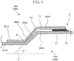
- an angle ⁇ ' formed between the outer circumferential surface of the suction pipe widening diameter portion 263A and a direction in which the suction pipe small diameter portion 261A extends is smaller than an angle ⁇ ' between the inner circumferential surface of the guide pipe widening diameter portion 303A and a direction in which the guide pipe small diameter portion 301A extends.
- the first suction pipe 26A (the second suction pipe 26B) is further pushed into the first guide pipe 30A (the second guide pipe 30B) from this state
- the first suction pipe 26A (the second suction pipe 26B) is slightly deformed such that the outer circumferential surface of the suction pipe widening diameter portion 263A approaches the inner circumferential surface of the guide pipe widening diameter portion 303A. That is, even in the case in which an excessively large force is applied when the first suction pipe 26A (the second suction pipe 26B) is inserted, the force is absorbed by deforming the first suction pipe 26A (the second suction pipe 26B) in the shock-absorbing space Vb'. As a result, the first suction pipe 26A (the second suction pipe 26B) can be prevented from being excessively pushed into the first guide pipe 30A (the second guide pipe 30B).
- the inner circumferential surface of the guide pipe widening diameter portion 303A and the outer circumferential surface of the suction pipe widening diameter portion 263A can securely come in contact with each other.
- sealability between the first suction pipe 26A and the first guide pipe 30A can be further improved.
Landscapes
- Engineering & Computer Science (AREA)
- Mechanical Engineering (AREA)
- General Engineering & Computer Science (AREA)
- Applications Or Details Of Rotary Compressors (AREA)
- Compressor (AREA)
Claims (2)
- Verdichtersystem (100), das Folgendes umfasst:eine Kurbelwelle (16), die dazu ausgelegt ist, sich um eine Achse (O) davon zu drehen;eine Verdichtungsmechanismuseinheit (10A), die einen Kolbenrotor (13A, 13B), der dazu ausgelegt ist, sich exzentrisch mit der Drehung der Kurbelwelle (16) zu drehen, und einen Zylinder (12A, 12B) mit einer Verdichtungskammer (R1, R2), in die der Kolbenrotor (13A, 13B) aufgenommen ist, der darin gebildet ist, beinhaltet;ein Gehäuse (11), in das die Kurbelwelle (16) und die Verdichtungsmechanismuseinheit (10A) aufgenommen sind und durch das ein Hochdruckkältemittel fließt, das von der Verdichtungsmechanismuseinheit (10A) erzeugt wird;eine Führungsleitung (30A, 30B), die koaxial zu einem Ansauganschluss (23A, 23B), der im Zylinder (12A, 12B) gebildet ist, angeordnet ist und befestigt ist, während sie in eine Öffnung (22A, 22B), die im Gehäuse (11) gebildet ist, gesteckt ist;einen Akkumulator (24), in dem sich das Kältemittel befindet; undeine Saugleitung (26A, 26B), die durch die Führungsleitung (30A, 30B) und den Ansauganschluss (23A, 23B) gesteckt und dazu ausgelegt ist, das Kältemittel vor der Verdichtung der Verdichtungskammer (R1, R2) vom Akkumulator (24) zuzuführen,wobei ein Endabschnitt des Ansauganschlusses (23A, 23B) auf der Saugleitungsseite in einer Position von einer Innenfläche des Gehäuses (11) weg bereitgestellt ist,die Führungsleitung (30A, 30B) weist Folgendes auf:einen Abschnitt (301A) der Führungsleitung mit kleinem Durchmesser, der in einer Position nahe des Ansauganschlusses (23A, 23B) gebildet ist;einen Abschnitt (302A) der Führungsleitung mit großem Durchmesser, der einen Durchmesser aufweist, der größer ist als der des Abschnitts (301A) der Führungsleitung mit kleinem Durchmesser; undeinen Abschnitt (303A) der Führungsleitung mit sich aufweitendem Durchmesser, der den Abschnitt (301A) der Führungsleitung mit kleinem Durchmesser mit dem Abschnitt (302A) der Führungsleitung mit großem Durchmesser verbindet und einen Durchmesser aufweist, der sich vom Abschnitt (301A) der Führungsleitung mit kleinem Durchmesser zum Abschnitt (302A) der Führungsleitung mit großem Durchmesser allmählich vergrößert, unddie Saugleitung (26A, 26B) weist Folgendes auf:einen Abschnitt (261A) der Saugleitung mit kleinem Durchmesser, der durch den Abschnitt (301A) der Führungsleitung mit kleinem Durchmesser gesteckt ist;einen Abschnitt (262A) der Saugleitung mit großem Durchmesser, der durch den Abschnitt (302A) der Führungsleitung mit großem Durchmesser gesteckt ist und der einen Durchmesser aufweist, der größer ist als der des Abschnitts (301A) der Führungsleitung mit kleinem Durchmesser; undeinen Abschnitt (263A) der Saugleitung mit sich aufweitendem Durchmesser, der den Abschnitt (261A) der Saugleitung mit kleinem Durchmesser mit dem Abschnitt (262A) der Saugleitung mit großem Durchmesser verbindet und einen Durchmesser aufweist, der sich vom Abschnitt (261A) der Saugleitung mit kleinem Durchmesser zum Abschnitt (262A) der Saugleitung mit großem Durchmesser allmählich vergrößert,wobei die Saugleitung (26A, 26B) ein Ende aufweist, das mit einem unteren Bereich des Akkumulators (24) verbunden ist, und ein anderes Ende, das mit dem Ansauganschluss (23A, 23B), der im Zylinder (12A, 12B) gebildet ist, durch die Öffnung (22A, 22B), die im Gehäuse (11) gebildet ist, verbunden ist; unddadurch gekennzeichnet, dass ein Winkel (α), der zwischen der Außenumfangsfläche des Abschnitts (263A) der Saugleitung mit sich aufweitendem Durchmesser und einer Richtung, in die sich der Abschnitt (261A) der Saugleitung mit kleinem Durchmesser erstreckt, größer ist als ein Winkel (β) zwischen der Innenumfangsfläche des Abschnitts (303A) der Führungsleitung mit sich aufweitendem Durchmesser und einer Richtung, in die sich der Abschnitt (301A) der Führungsleitung mit kleinem Durchmesser erstreckt, derart, dass die Außenumfangsfläche des Abschnitts (263A) der Saugleitung mit sich aufweitendem Durchmesser an der Innenumfangsfläche des Abschnitts (303A) der Führungsleitung mit sich aufweitendem Durchmesser in einer Linienkontaktweise anliegt.
- Verdichtersystem (100) nach Anspruch 1, das ferner Folgendes umfasst:ein Paar von Verdichtungsmechanismuseinheiten (10A), die in einer Axialrichtung, in die sich die Achse (O) erstreckt, angeordnet sind;ein Paar von Führungsleitungen (30A, 30B), die an einem Paar von Öffnungen (22A, 22B) befestigt sind, die im Gehäuse (11) in Positionen gebildet sind, die in der Axialrichtung voneinander getrennt sind; undein Paar von Saugleitungen (26A, 26B), die durch die Führungsleitungen (30A, 30B) und durch die Ansauganschlüsse (23A, 23B), die im Zylinder (12A, 12B) gebildet sind, gesteckt sind.
Applications Claiming Priority (1)
| Application Number | Priority Date | Filing Date | Title |
|---|---|---|---|
| JP2018073208A JP7080092B2 (ja) | 2018-04-05 | 2018-04-05 | 圧縮機システム |
Publications (2)
| Publication Number | Publication Date |
|---|---|
| EP3550146A1 EP3550146A1 (de) | 2019-10-09 |
| EP3550146B1 true EP3550146B1 (de) | 2021-05-19 |
Family
ID=66092100
Family Applications (1)
| Application Number | Title | Priority Date | Filing Date |
|---|---|---|---|
| EP19167139.5A Active EP3550146B1 (de) | 2018-04-05 | 2019-04-03 | Verdichtersystem |
Country Status (2)
| Country | Link |
|---|---|
| EP (1) | EP3550146B1 (de) |
| JP (1) | JP7080092B2 (de) |
Families Citing this family (1)
| Publication number | Priority date | Publication date | Assignee | Title |
|---|---|---|---|---|
| CN112145436B (zh) * | 2020-08-27 | 2022-08-05 | 珠海格力节能环保制冷技术研究中心有限公司 | 一种吸气装置、压缩组件和空调器 |
Family Cites Families (5)
| Publication number | Priority date | Publication date | Assignee | Title |
|---|---|---|---|---|
| JPS5956392U (ja) * | 1982-10-06 | 1984-04-12 | 株式会社東芝 | ロ−タリコンプレツサ |
| JPS59131781A (ja) * | 1983-12-20 | 1984-07-28 | Sanyo Electric Co Ltd | 密閉形電動圧縮機 |
| KR101386481B1 (ko) | 2008-03-05 | 2014-04-18 | 엘지전자 주식회사 | 밀폐형 압축기 |
| JP2012136967A (ja) | 2010-12-24 | 2012-07-19 | Daikin Industries Ltd | 二段圧縮機 |
| JP6645845B2 (ja) | 2016-01-26 | 2020-02-14 | 三菱重工サーマルシステムズ株式会社 | 複数の配管を有するアキュムレータおよび圧縮機 |
-
2018
- 2018-04-05 JP JP2018073208A patent/JP7080092B2/ja active Active
-
2019
- 2019-04-03 EP EP19167139.5A patent/EP3550146B1/de active Active
Non-Patent Citations (1)
| Title |
|---|
| None * |
Also Published As
| Publication number | Publication date |
|---|---|
| EP3550146A1 (de) | 2019-10-09 |
| JP7080092B2 (ja) | 2022-06-03 |
| JP2019183702A (ja) | 2019-10-24 |
Similar Documents
| Publication | Publication Date | Title |
|---|---|---|
| JP6187266B2 (ja) | 電動圧縮機 | |
| KR102292995B1 (ko) | 스크롤형 압축기 | |
| US20110002797A1 (en) | Rotary machine | |
| KR20180103722A (ko) | 나선 원리에 따른 용적형 기계, 용적형 기계를 작동시키기 위한 방법, 용적형 스파이럴, 차량 공기 조화 시스템, 및 차량 | |
| WO2017158665A1 (ja) | スクロール圧縮機 | |
| US9885359B2 (en) | Motor-driven compressor | |
| US10087934B2 (en) | Vane compressor | |
| EP3550146B1 (de) | Verdichtersystem | |
| CN113396285B (zh) | 旋转式压缩机、旋转式压缩机的制造方法及制冷循环装置 | |
| EP3550147B1 (de) | Verdichtersystem | |
| JP2014132158A (ja) | スクロール型圧縮機 | |
| US10125770B2 (en) | Cylinder-rotation compressor with a discharge valve | |
| US11965508B2 (en) | Scroll compressor | |
| EP3141754B1 (de) | Drehkompressor und verfahren zur herstellung davon | |
| WO2015005090A1 (ja) | 気体圧縮機の気密端子固定構造 | |
| JP2015040536A (ja) | スクロール圧縮機 | |
| JP6374737B2 (ja) | シリンダ回転型圧縮機 | |
| EP3557067B1 (de) | Kolbenrotor, kurbelwelle, rotationsverdichter und verfahren zur montage der kurbelwelle | |
| CN106662105B (zh) | 涡旋式压缩机 | |
| US10253773B2 (en) | Attachment structure for compressor | |
| JP4489514B2 (ja) | 気体圧縮機 | |
| WO2019187272A1 (ja) | ロータリコンプレッサ | |
| CN116771672A (zh) | 涡旋型压缩机 | |
| US20190203714A1 (en) | Rotary cylinder type compressor | |
| US20190301450A1 (en) | Compressor |
Legal Events
| Date | Code | Title | Description |
|---|---|---|---|
| PUAI | Public reference made under article 153(3) epc to a published international application that has entered the european phase |
Free format text: ORIGINAL CODE: 0009012 |
|
| STAA | Information on the status of an ep patent application or granted ep patent |
Free format text: STATUS: THE APPLICATION HAS BEEN PUBLISHED |
|
| AK | Designated contracting states |
Kind code of ref document: A1 Designated state(s): AL AT BE BG CH CY CZ DE DK EE ES FI FR GB GR HR HU IE IS IT LI LT LU LV MC MK MT NL NO PL PT RO RS SE SI SK SM TR |
|
| AX | Request for extension of the european patent |
Extension state: BA ME |
|
| STAA | Information on the status of an ep patent application or granted ep patent |
Free format text: STATUS: REQUEST FOR EXAMINATION WAS MADE |
|
| 17P | Request for examination filed |
Effective date: 20200410 |
|
| RBV | Designated contracting states (corrected) |
Designated state(s): AL AT BE BG CH CY CZ DE DK EE ES FI FR GB GR HR HU IE IS IT LI LT LU LV MC MK MT NL NO PL PT RO RS SE SI SK SM TR |
|
| STAA | Information on the status of an ep patent application or granted ep patent |
Free format text: STATUS: EXAMINATION IS IN PROGRESS |
|
| 17Q | First examination report despatched |
Effective date: 20200605 |
|
| GRAP | Despatch of communication of intention to grant a patent |
Free format text: ORIGINAL CODE: EPIDOSNIGR1 |
|
| STAA | Information on the status of an ep patent application or granted ep patent |
Free format text: STATUS: GRANT OF PATENT IS INTENDED |
|
| INTG | Intention to grant announced |
Effective date: 20210104 |
|
| INTG | Intention to grant announced |
Effective date: 20210113 |
|
| GRAS | Grant fee paid |
Free format text: ORIGINAL CODE: EPIDOSNIGR3 |
|
| GRAA | (expected) grant |
Free format text: ORIGINAL CODE: 0009210 |
|
| STAA | Information on the status of an ep patent application or granted ep patent |
Free format text: STATUS: THE PATENT HAS BEEN GRANTED |
|
| AK | Designated contracting states |
Kind code of ref document: B1 Designated state(s): AL AT BE BG CH CY CZ DE DK EE ES FI FR GB GR HR HU IE IS IT LI LT LU LV MC MK MT NL NO PL PT RO RS SE SI SK SM TR |
|
| REG | Reference to a national code |
Ref country code: GB Ref legal event code: FG4D |
|
| REG | Reference to a national code |
Ref country code: CH Ref legal event code: EP |
|
| REG | Reference to a national code |
Ref country code: DE Ref legal event code: R096 Ref document number: 602019004633 Country of ref document: DE |
|
| REG | Reference to a national code |
Ref country code: AT Ref legal event code: REF Ref document number: 1394234 Country of ref document: AT Kind code of ref document: T Effective date: 20210615 |
|
| REG | Reference to a national code |
Ref country code: IE Ref legal event code: FG4D |
|
| REG | Reference to a national code |
Ref country code: LT Ref legal event code: MG9D |
|
| REG | Reference to a national code |
Ref country code: AT Ref legal event code: MK05 Ref document number: 1394234 Country of ref document: AT Kind code of ref document: T Effective date: 20210519 |
|
| REG | Reference to a national code |
Ref country code: NL Ref legal event code: MP Effective date: 20210519 |
|
| PG25 | Lapsed in a contracting state [announced via postgrant information from national office to epo] |
Ref country code: HR Free format text: LAPSE BECAUSE OF FAILURE TO SUBMIT A TRANSLATION OF THE DESCRIPTION OR TO PAY THE FEE WITHIN THE PRESCRIBED TIME-LIMIT Effective date: 20210519 Ref country code: LT Free format text: LAPSE BECAUSE OF FAILURE TO SUBMIT A TRANSLATION OF THE DESCRIPTION OR TO PAY THE FEE WITHIN THE PRESCRIBED TIME-LIMIT Effective date: 20210519 Ref country code: FI Free format text: LAPSE BECAUSE OF FAILURE TO SUBMIT A TRANSLATION OF THE DESCRIPTION OR TO PAY THE FEE WITHIN THE PRESCRIBED TIME-LIMIT Effective date: 20210519 Ref country code: BG Free format text: LAPSE BECAUSE OF FAILURE TO SUBMIT A TRANSLATION OF THE DESCRIPTION OR TO PAY THE FEE WITHIN THE PRESCRIBED TIME-LIMIT Effective date: 20210819 Ref country code: AT Free format text: LAPSE BECAUSE OF FAILURE TO SUBMIT A TRANSLATION OF THE DESCRIPTION OR TO PAY THE FEE WITHIN THE PRESCRIBED TIME-LIMIT Effective date: 20210519 |
|
| PG25 | Lapsed in a contracting state [announced via postgrant information from national office to epo] |
Ref country code: IS Free format text: LAPSE BECAUSE OF FAILURE TO SUBMIT A TRANSLATION OF THE DESCRIPTION OR TO PAY THE FEE WITHIN THE PRESCRIBED TIME-LIMIT Effective date: 20210919 Ref country code: GR Free format text: LAPSE BECAUSE OF FAILURE TO SUBMIT A TRANSLATION OF THE DESCRIPTION OR TO PAY THE FEE WITHIN THE PRESCRIBED TIME-LIMIT Effective date: 20210820 Ref country code: LV Free format text: LAPSE BECAUSE OF FAILURE TO SUBMIT A TRANSLATION OF THE DESCRIPTION OR TO PAY THE FEE WITHIN THE PRESCRIBED TIME-LIMIT Effective date: 20210519 Ref country code: PL Free format text: LAPSE BECAUSE OF FAILURE TO SUBMIT A TRANSLATION OF THE DESCRIPTION OR TO PAY THE FEE WITHIN THE PRESCRIBED TIME-LIMIT Effective date: 20210519 Ref country code: NO Free format text: LAPSE BECAUSE OF FAILURE TO SUBMIT A TRANSLATION OF THE DESCRIPTION OR TO PAY THE FEE WITHIN THE PRESCRIBED TIME-LIMIT Effective date: 20210819 Ref country code: PT Free format text: LAPSE BECAUSE OF FAILURE TO SUBMIT A TRANSLATION OF THE DESCRIPTION OR TO PAY THE FEE WITHIN THE PRESCRIBED TIME-LIMIT Effective date: 20210920 Ref country code: RS Free format text: LAPSE BECAUSE OF FAILURE TO SUBMIT A TRANSLATION OF THE DESCRIPTION OR TO PAY THE FEE WITHIN THE PRESCRIBED TIME-LIMIT Effective date: 20210519 Ref country code: SE Free format text: LAPSE BECAUSE OF FAILURE TO SUBMIT A TRANSLATION OF THE DESCRIPTION OR TO PAY THE FEE WITHIN THE PRESCRIBED TIME-LIMIT Effective date: 20210519 |
|
| PG25 | Lapsed in a contracting state [announced via postgrant information from national office to epo] |
Ref country code: NL Free format text: LAPSE BECAUSE OF FAILURE TO SUBMIT A TRANSLATION OF THE DESCRIPTION OR TO PAY THE FEE WITHIN THE PRESCRIBED TIME-LIMIT Effective date: 20210519 |
|
| PG25 | Lapsed in a contracting state [announced via postgrant information from national office to epo] |
Ref country code: CZ Free format text: LAPSE BECAUSE OF FAILURE TO SUBMIT A TRANSLATION OF THE DESCRIPTION OR TO PAY THE FEE WITHIN THE PRESCRIBED TIME-LIMIT Effective date: 20210519 Ref country code: DK Free format text: LAPSE BECAUSE OF FAILURE TO SUBMIT A TRANSLATION OF THE DESCRIPTION OR TO PAY THE FEE WITHIN THE PRESCRIBED TIME-LIMIT Effective date: 20210519 Ref country code: SM Free format text: LAPSE BECAUSE OF FAILURE TO SUBMIT A TRANSLATION OF THE DESCRIPTION OR TO PAY THE FEE WITHIN THE PRESCRIBED TIME-LIMIT Effective date: 20210519 Ref country code: RO Free format text: LAPSE BECAUSE OF FAILURE TO SUBMIT A TRANSLATION OF THE DESCRIPTION OR TO PAY THE FEE WITHIN THE PRESCRIBED TIME-LIMIT Effective date: 20210519 Ref country code: EE Free format text: LAPSE BECAUSE OF FAILURE TO SUBMIT A TRANSLATION OF THE DESCRIPTION OR TO PAY THE FEE WITHIN THE PRESCRIBED TIME-LIMIT Effective date: 20210519 Ref country code: ES Free format text: LAPSE BECAUSE OF FAILURE TO SUBMIT A TRANSLATION OF THE DESCRIPTION OR TO PAY THE FEE WITHIN THE PRESCRIBED TIME-LIMIT Effective date: 20210519 Ref country code: SK Free format text: LAPSE BECAUSE OF FAILURE TO SUBMIT A TRANSLATION OF THE DESCRIPTION OR TO PAY THE FEE WITHIN THE PRESCRIBED TIME-LIMIT Effective date: 20210519 |
|
| REG | Reference to a national code |
Ref country code: DE Ref legal event code: R097 Ref document number: 602019004633 Country of ref document: DE |
|
| PLBE | No opposition filed within time limit |
Free format text: ORIGINAL CODE: 0009261 |
|
| STAA | Information on the status of an ep patent application or granted ep patent |
Free format text: STATUS: NO OPPOSITION FILED WITHIN TIME LIMIT |
|
| 26N | No opposition filed |
Effective date: 20220222 |
|
| PG25 | Lapsed in a contracting state [announced via postgrant information from national office to epo] |
Ref country code: IS Free format text: LAPSE BECAUSE OF FAILURE TO SUBMIT A TRANSLATION OF THE DESCRIPTION OR TO PAY THE FEE WITHIN THE PRESCRIBED TIME-LIMIT Effective date: 20210919 Ref country code: AL Free format text: LAPSE BECAUSE OF FAILURE TO SUBMIT A TRANSLATION OF THE DESCRIPTION OR TO PAY THE FEE WITHIN THE PRESCRIBED TIME-LIMIT Effective date: 20210519 |
|
| PG25 | Lapsed in a contracting state [announced via postgrant information from national office to epo] |
Ref country code: IT Free format text: LAPSE BECAUSE OF FAILURE TO SUBMIT A TRANSLATION OF THE DESCRIPTION OR TO PAY THE FEE WITHIN THE PRESCRIBED TIME-LIMIT Effective date: 20210519 |
|
| REG | Reference to a national code |
Ref country code: CH Ref legal event code: PL |
|
| REG | Reference to a national code |
Ref country code: BE Ref legal event code: MM Effective date: 20220430 |
|
| PG25 | Lapsed in a contracting state [announced via postgrant information from national office to epo] |
Ref country code: MC Free format text: LAPSE BECAUSE OF FAILURE TO SUBMIT A TRANSLATION OF THE DESCRIPTION OR TO PAY THE FEE WITHIN THE PRESCRIBED TIME-LIMIT Effective date: 20210519 Ref country code: LU Free format text: LAPSE BECAUSE OF NON-PAYMENT OF DUE FEES Effective date: 20220403 Ref country code: LI Free format text: LAPSE BECAUSE OF NON-PAYMENT OF DUE FEES Effective date: 20220430 Ref country code: CH Free format text: LAPSE BECAUSE OF NON-PAYMENT OF DUE FEES Effective date: 20220430 |
|
| PG25 | Lapsed in a contracting state [announced via postgrant information from national office to epo] |
Ref country code: BE Free format text: LAPSE BECAUSE OF NON-PAYMENT OF DUE FEES Effective date: 20220430 |
|
| REG | Reference to a national code |
Ref country code: DE Ref legal event code: R082 Ref document number: 602019004633 Country of ref document: DE Representative=s name: CBDL PATENTANWAELTE GBR, DE Ref country code: DE Ref legal event code: R082 Ref document number: 602019004633 Country of ref document: DE Representative=s name: CBDL PATENTANWAELTE EGBR, DE |
|
| PG25 | Lapsed in a contracting state [announced via postgrant information from national office to epo] |
Ref country code: IE Free format text: LAPSE BECAUSE OF NON-PAYMENT OF DUE FEES Effective date: 20220403 |
|
| PG25 | Lapsed in a contracting state [announced via postgrant information from national office to epo] |
Ref country code: HU Free format text: LAPSE BECAUSE OF FAILURE TO SUBMIT A TRANSLATION OF THE DESCRIPTION OR TO PAY THE FEE WITHIN THE PRESCRIBED TIME-LIMIT; INVALID AB INITIO Effective date: 20190403 |
|
| PG25 | Lapsed in a contracting state [announced via postgrant information from national office to epo] |
Ref country code: MK Free format text: LAPSE BECAUSE OF FAILURE TO SUBMIT A TRANSLATION OF THE DESCRIPTION OR TO PAY THE FEE WITHIN THE PRESCRIBED TIME-LIMIT Effective date: 20210519 Ref country code: CY Free format text: LAPSE BECAUSE OF FAILURE TO SUBMIT A TRANSLATION OF THE DESCRIPTION OR TO PAY THE FEE WITHIN THE PRESCRIBED TIME-LIMIT Effective date: 20210519 |
|
| PG25 | Lapsed in a contracting state [announced via postgrant information from national office to epo] |
Ref country code: MT Free format text: LAPSE BECAUSE OF FAILURE TO SUBMIT A TRANSLATION OF THE DESCRIPTION OR TO PAY THE FEE WITHIN THE PRESCRIBED TIME-LIMIT Effective date: 20210519 |
|
| PGFP | Annual fee paid to national office [announced via postgrant information from national office to epo] |
Ref country code: DE Payment date: 20250305 Year of fee payment: 7 |
|
| PG25 | Lapsed in a contracting state [announced via postgrant information from national office to epo] |
Ref country code: TR Free format text: LAPSE BECAUSE OF FAILURE TO SUBMIT A TRANSLATION OF THE DESCRIPTION OR TO PAY THE FEE WITHIN THE PRESCRIBED TIME-LIMIT Effective date: 20210519 |
|
| PGFP | Annual fee paid to national office [announced via postgrant information from national office to epo] |
Ref country code: GB Payment date: 20260313 Year of fee payment: 8 |
|
| PGFP | Annual fee paid to national office [announced via postgrant information from national office to epo] |
Ref country code: FR Payment date: 20260309 Year of fee payment: 8 |