EP3550135A1 - Aktivierungsverfahren bei einem elektrisch gesteuerten common-rail-motor - Google Patents
Aktivierungsverfahren bei einem elektrisch gesteuerten common-rail-motor Download PDFInfo
- Publication number
- EP3550135A1 EP3550135A1 EP17896851.7A EP17896851A EP3550135A1 EP 3550135 A1 EP3550135 A1 EP 3550135A1 EP 17896851 A EP17896851 A EP 17896851A EP 3550135 A1 EP3550135 A1 EP 3550135A1
- Authority
- EP
- European Patent Office
- Prior art keywords
- gas discharging
- fine filter
- fuel
- discharging device
- common rail
- Prior art date
- Legal status (The legal status is an assumption and is not a legal conclusion. Google has not performed a legal analysis and makes no representation as to the accuracy of the status listed.)
- Withdrawn
Links
- 230000004913 activation Effects 0.000 title claims abstract description 32
- 238000000034 method Methods 0.000 title description 4
- 238000007599 discharging Methods 0.000 claims abstract description 68
- 239000007789 gas Substances 0.000 claims abstract description 65
- 239000000446 fuel Substances 0.000 claims abstract description 36
- 238000012546 transfer Methods 0.000 claims abstract description 17
- 239000002828 fuel tank Substances 0.000 claims abstract description 16
- 239000002737 fuel gas Substances 0.000 claims abstract description 4
- 238000002347 injection Methods 0.000 claims description 11
- 239000007924 injection Substances 0.000 claims description 11
- 238000012360 testing method Methods 0.000 claims description 4
- 238000012795 verification Methods 0.000 claims description 3
- 229910000831 Steel Inorganic materials 0.000 description 3
- 238000012986 modification Methods 0.000 description 3
- 230000004048 modification Effects 0.000 description 3
- 238000011045 prefiltration Methods 0.000 description 3
- 238000007789 sealing Methods 0.000 description 3
- 239000010959 steel Substances 0.000 description 3
- 230000000694 effects Effects 0.000 description 2
- 230000009286 beneficial effect Effects 0.000 description 1
- 238000013461 design Methods 0.000 description 1
- 238000010586 diagram Methods 0.000 description 1
- 230000002035 prolonged effect Effects 0.000 description 1
- 238000004904 shortening Methods 0.000 description 1
Images


Classifications
-
- F—MECHANICAL ENGINEERING; LIGHTING; HEATING; WEAPONS; BLASTING
- F02—COMBUSTION ENGINES; HOT-GAS OR COMBUSTION-PRODUCT ENGINE PLANTS
- F02M—SUPPLYING COMBUSTION ENGINES IN GENERAL WITH COMBUSTIBLE MIXTURES OR CONSTITUENTS THEREOF
- F02M37/00—Apparatus or systems for feeding liquid fuel from storage containers to carburettors or fuel-injection apparatus; Arrangements for purifying liquid fuel specially adapted for, or arranged on, internal-combustion engines
- F02M37/20—Apparatus or systems for feeding liquid fuel from storage containers to carburettors or fuel-injection apparatus; Arrangements for purifying liquid fuel specially adapted for, or arranged on, internal-combustion engines characterised by means for preventing vapour lock
-
- F—MECHANICAL ENGINEERING; LIGHTING; HEATING; WEAPONS; BLASTING
- F02—COMBUSTION ENGINES; HOT-GAS OR COMBUSTION-PRODUCT ENGINE PLANTS
- F02M—SUPPLYING COMBUSTION ENGINES IN GENERAL WITH COMBUSTIBLE MIXTURES OR CONSTITUENTS THEREOF
- F02M37/00—Apparatus or systems for feeding liquid fuel from storage containers to carburettors or fuel-injection apparatus; Arrangements for purifying liquid fuel specially adapted for, or arranged on, internal-combustion engines
- F02M37/0011—Constructional details; Manufacturing or assembly of elements of fuel systems; Materials therefor
- F02M37/0023—Valves in the fuel supply and return system
-
- F—MECHANICAL ENGINEERING; LIGHTING; HEATING; WEAPONS; BLASTING
- F02—COMBUSTION ENGINES; HOT-GAS OR COMBUSTION-PRODUCT ENGINE PLANTS
- F02M—SUPPLYING COMBUSTION ENGINES IN GENERAL WITH COMBUSTIBLE MIXTURES OR CONSTITUENTS THEREOF
- F02M37/00—Apparatus or systems for feeding liquid fuel from storage containers to carburettors or fuel-injection apparatus; Arrangements for purifying liquid fuel specially adapted for, or arranged on, internal-combustion engines
- F02M37/22—Arrangements for purifying liquid fuel specially adapted for, or arranged on, internal-combustion engines, e.g. arrangements in the feeding system
- F02M37/32—Arrangements for purifying liquid fuel specially adapted for, or arranged on, internal-combustion engines, e.g. arrangements in the feeding system characterised by filters or filter arrangements
-
- F—MECHANICAL ENGINEERING; LIGHTING; HEATING; WEAPONS; BLASTING
- F02—COMBUSTION ENGINES; HOT-GAS OR COMBUSTION-PRODUCT ENGINE PLANTS
- F02M—SUPPLYING COMBUSTION ENGINES IN GENERAL WITH COMBUSTIBLE MIXTURES OR CONSTITUENTS THEREOF
- F02M37/00—Apparatus or systems for feeding liquid fuel from storage containers to carburettors or fuel-injection apparatus; Arrangements for purifying liquid fuel specially adapted for, or arranged on, internal-combustion engines
- F02M37/22—Arrangements for purifying liquid fuel specially adapted for, or arranged on, internal-combustion engines, e.g. arrangements in the feeding system
- F02M37/54—Arrangements for purifying liquid fuel specially adapted for, or arranged on, internal-combustion engines, e.g. arrangements in the feeding system characterised by air purging means
-
- F—MECHANICAL ENGINEERING; LIGHTING; HEATING; WEAPONS; BLASTING
- F02—COMBUSTION ENGINES; HOT-GAS OR COMBUSTION-PRODUCT ENGINE PLANTS
- F02M—SUPPLYING COMBUSTION ENGINES IN GENERAL WITH COMBUSTIBLE MIXTURES OR CONSTITUENTS THEREOF
- F02M37/00—Apparatus or systems for feeding liquid fuel from storage containers to carburettors or fuel-injection apparatus; Arrangements for purifying liquid fuel specially adapted for, or arranged on, internal-combustion engines
- F02M37/04—Feeding by means of driven pumps
Definitions
- the present invention relates to the field of engines, in particular, to a care-free activation system of an electrically controlled common rail engine.
- an existing electrically controlled common rail engine a fuel system is an important factor affecting activation performance thereof.
- an existing common rail system mainly improves the activation performance of an engine by optimizing system components and optimizing a complete machine layout design.
- An electronic fuel transfer pump is added to some engines to speed up gas discharging of an oil channel, so a purpose of speeding up the activation can be achieved, and complete machine costs may be increased.
- presence of gas from a fuel transfer pump to a fuel injection pump affects the activation performance.
- the present invention is directed to a care-free activation system of an electrically controlled common rail engine, which can effectively increase activation performance of the engine.
- the gas discharging device is a one-way valve.
- an opening pressure of the gas discharging device is between 1.5 bar and 6 bar.
- the gas discharging device is arranged on the fine filter.
- the present invention by arranging the gas discharging device at the oil feeding port of the fine filter, air in the fine filter can be discharged via the gas discharging device, thereby implementing active gas discharging, and effectively increasing activation performance of the engine.
- the present invention is ingenious in structure and high in reliability, and effectively reduces costs due to no additional control system.
- the present invention can significantly increase activation speed of an engine.
- the present invention provides a care-free activation system of an electrically controlled common rail engine.
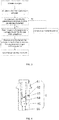
- the system includes a fuel tank 1, a pre-filter 2, a fuel transfer pump 3, a fine filter 4, and a fuel injection pump 5.
- the fuel tank 1 is sequentially connected to the pre-filter 2, the fuel transfer pump 3, the fine filter 4, and the fuel injection pump 5 via an oil pipe 7.
- a fuel return port of the fuel injection pump 5 is also connected to the fuel tank 1 via the oil pipe 7.
- a gas discharging device 6 discharging fuel gas is arranged between the fuel transfer pump 3 and the fuel injection pump 5.
- An outlet of the gas discharging device 6 communicates with the fuel tank 1 via the oil pipe.
- a fixing mount 42 is arranged at an oil feeding port 41 of the fine filter 4. The gas discharging device 6 is fixed to the fine filter 4 via the fixing mount 42.
- the gas discharging device 6 and the fixing mount 42 are connected tightly through screw threads to fix the gas discharging device 6 to the fine filter 4. An influence of vibration of an engine during normal operation on the gas discharging device 6 can be effectively avoided. Normal service life of the gas discharging device 6 can be prolonged, and operation stability can be increased.
- the gas discharging device 6 may also be connected to two segments of connecting oil pipe 7 between an oil outlet of the fuel transfer pump 3 and an oil inlet of the fuel injection pump 5 via a three-way joint.
- the gas discharging device 6 is a one-way valve.
- the gas discharging device 6 includes a valve body 61, a valve body inlet 66 provided at one end of the valve body 61, and a gas discharging hole 62 provided on a side surface of the valve body 61.
- the valve body inlet 66 communicates with the fixing mount 42.
- the gas discharging hole 62 communicates with the fuel tank 1 via the oil pipe.
- a hole diameter of the gas discharging hole 62 is 0.5 mm.
- the hole diameter of the gas discharging hole 62 is preset according to the above formula with the experimental data before installing the gas discharging device 6, and the hole diameter of the gas discharging hole 62 is verified according to the above formula with the experimental data measured after installing the gas discharging device 6, so that the gas discharging device 6 can ensure sufficient gas discharging capability, and avoid excessive fuel flowing back to the fuel tank 1 via the gas discharging hole, thereby not affecting the normal operation of the engine.
- An opening pressure of the one-way valve is 5 bar.
- the opening pressure of the one-way valve may also be 1.5 bar or 2 bar or 3 bar or 4 bar or 6 bar.
- the hole diameter of the gas discharging hole 62 may also be 0.2 mm or 0.7 mm or 1 mm or 1.5 mm or 2 mm or 3 mm.
- Table 1 Number of tests Gas discharging hole (mm) start drag (s) Axial pressure setup start (s) Axial pressure closed (s) Ignition time (s) Activation time (s) Axial pressure setup to delay (s) Axial pressure setup to closed loop (s) successful ignition (s) 0 7.014 8.794 9.324 9.364 2.66 1.78 0.53 0.31 1 0.5 4.838 5.666 6.066 6.186 1.619 0.828 0.4 0.271 2 0.5 5.926 6.836 7.307 7.467 1.77 0.91 0.471 0.229
Landscapes
- Engineering & Computer Science (AREA)
- Chemical & Material Sciences (AREA)
- Combustion & Propulsion (AREA)
- Mechanical Engineering (AREA)
- General Engineering & Computer Science (AREA)
- Fuel-Injection Apparatus (AREA)
- Lubrication Details And Ventilation Of Internal Combustion Engines (AREA)
Applications Claiming Priority (2)
| Application Number | Priority Date | Filing Date | Title |
|---|---|---|---|
| CN201710088361.XA CN107061082A (zh) | 2017-02-17 | 2017-02-17 | 电控共轨发动机无忧启动系统 |
| PCT/CN2017/106273 WO2018149160A1 (zh) | 2017-02-17 | 2017-10-23 | 电控共轨发动机无忧启动系统 |
Publications (2)
| Publication Number | Publication Date |
|---|---|
| EP3550135A1 true EP3550135A1 (de) | 2019-10-09 |
| EP3550135A4 EP3550135A4 (de) | 2019-12-04 |
Family
ID=59622744
Family Applications (1)
| Application Number | Title | Priority Date | Filing Date |
|---|---|---|---|
| EP17896851.7A Withdrawn EP3550135A4 (de) | 2017-02-17 | 2017-10-23 | Aktivierungsverfahren bei einem elektrisch gesteuerten common-rail-motor |
Country Status (4)
| Country | Link |
|---|---|
| US (1) | US20190331074A1 (de) |
| EP (1) | EP3550135A4 (de) |
| CN (1) | CN107061082A (de) |
| WO (1) | WO2018149160A1 (de) |
Families Citing this family (4)
| Publication number | Priority date | Publication date | Assignee | Title |
|---|---|---|---|---|
| CN106837642A (zh) * | 2017-02-17 | 2017-06-13 | 广西玉柴机器股份有限公司 | 一种电控共轨发动机快速启动方法 |
| CN107061082A (zh) * | 2017-02-17 | 2017-08-18 | 广西玉柴机器股份有限公司 | 电控共轨发动机无忧启动系统 |
| CN111472905B (zh) * | 2020-04-07 | 2025-08-15 | 三一重机有限公司 | 旋挖钻机燃油系统、旋挖钻机及燃油系统控制方法 |
| CN117622496B (zh) * | 2024-01-23 | 2024-06-04 | 西安爱生技术集团有限公司 | 一种适于电控发动机的无人机燃油系统及设计方法 |
Family Cites Families (22)
| Publication number | Priority date | Publication date | Assignee | Title |
|---|---|---|---|---|
| US5544483A (en) * | 1993-02-19 | 1996-08-13 | Volkswagen Ag | Internal combustion engine with a secondary air-fuel supply |
| CN100379974C (zh) * | 2000-09-20 | 2008-04-09 | 三国株式会社 | 燃料供应装置和用于该燃料供应装置的燃料过滤器 |
| US6959696B2 (en) * | 2002-04-12 | 2005-11-01 | Briggs & Stratton Corporation | Internal combustion engine evaporative emission control system |
| US7779818B2 (en) * | 2007-07-12 | 2010-08-24 | Caterpillar Inc. | System and method for priming a fluid system |
| US8186332B2 (en) * | 2009-07-20 | 2012-05-29 | Mann & Hummel Gmbh | Fluid filter with integrated temperature regulation |
| JP5786502B2 (ja) * | 2011-07-05 | 2015-09-30 | 浜名湖電装株式会社 | 蒸発燃料パージ装置 |
| JP5663624B2 (ja) * | 2013-03-26 | 2015-02-04 | 株式会社ミツバ | 燃料供給装置 |
| JP6036575B2 (ja) * | 2013-06-25 | 2016-11-30 | 京三電機株式会社 | 燃料フィルタ装置 |
| CN103742322A (zh) * | 2013-09-18 | 2014-04-23 | 任化一 | 一种柴油发动机油路自动排气装置 |
| CN203822509U (zh) * | 2014-04-30 | 2014-09-10 | 中国重汽集团济南动力有限公司 | 一种柴油机油路电控放气装置 |
| CN103953479A (zh) * | 2014-04-30 | 2014-07-30 | 中国重汽集团济南动力有限公司 | 一种柴油机油路电控放气装置 |
| JP5921618B2 (ja) * | 2014-08-08 | 2016-05-24 | ヤマハ発動機株式会社 | 燃料供給装置、燃料供給方法及び船舶推進装置 |
| US9611801B2 (en) * | 2014-12-15 | 2017-04-04 | Ford Global Technologies, Llc | Methods and systems for fixed and variable pressure fuel injection |
| CN204553029U (zh) * | 2015-03-09 | 2015-08-12 | 广西华原过滤系统股份有限公司 | 一种自动排气燃油过滤系统 |
| US10774799B2 (en) * | 2015-03-25 | 2020-09-15 | Cd Patents, Llc | Fuel-air separator and improved air bleed system |
| CN204716436U (zh) * | 2015-06-18 | 2015-10-21 | 常州市万航工矿设备有限公司 | 内燃机车供油装置 |
| CN105156241A (zh) * | 2015-08-24 | 2015-12-16 | 太仓澄天机械有限公司 | 一种柴油机燃油排空气装置 |
| CN205955876U (zh) * | 2016-07-04 | 2017-02-15 | 广西华原过滤系统股份有限公司 | 一种有助于改善发动机冷启动性能的新型柴油滤清器 |
| CN205936908U (zh) * | 2016-07-12 | 2017-02-08 | 潍柴动力股份有限公司 | 一种电控发动机燃油系统 |
| CN206448893U (zh) * | 2017-02-17 | 2017-08-29 | 广西玉柴机器股份有限公司 | 电控共轨发动机无忧启动系统 |
| CN107061082A (zh) * | 2017-02-17 | 2017-08-18 | 广西玉柴机器股份有限公司 | 电控共轨发动机无忧启动系统 |
| CN106837642A (zh) * | 2017-02-17 | 2017-06-13 | 广西玉柴机器股份有限公司 | 一种电控共轨发动机快速启动方法 |
-
2017
- 2017-02-17 CN CN201710088361.XA patent/CN107061082A/zh active Pending
- 2017-10-23 WO PCT/CN2017/106273 patent/WO2018149160A1/zh not_active Ceased
- 2017-10-23 US US16/468,294 patent/US20190331074A1/en not_active Abandoned
- 2017-10-23 EP EP17896851.7A patent/EP3550135A4/de not_active Withdrawn
Also Published As
| Publication number | Publication date |
|---|---|
| WO2018149160A1 (zh) | 2018-08-23 |
| CN107061082A (zh) | 2017-08-18 |
| US20190331074A1 (en) | 2019-10-31 |
| EP3550135A4 (de) | 2019-12-04 |
Similar Documents
| Publication | Publication Date | Title |
|---|---|---|
| EP3550137A1 (de) | Schnelles aktivierungsverfahren bei einem elektrisch gesteuerten common-rail-motor | |
| EP3550135A1 (de) | Aktivierungsverfahren bei einem elektrisch gesteuerten common-rail-motor | |
| US7617991B2 (en) | Injector fuel filter with built-in orifice for flow restriction | |
| US7527043B2 (en) | Liquid fuel system with anti-drainback valve and engine using same | |
| WO2006074833A1 (de) | Abgasnachbehandlungsverfahren und vorrichtung hierzu | |
| CN105526025A (zh) | 蒸发燃料净化系统 | |
| US8931261B2 (en) | Apparatus, system, and method for diverting fluid | |
| JPH0427757A (ja) | 水噴射ディーゼルエンジン | |
| CN104421074A (zh) | 包括集成止回阀的燃料输送系统 | |
| JP5804639B2 (ja) | 燃料漏れ検出方法及びコモンレール式燃料噴射制御装置 | |
| JPH1082351A (ja) | 内燃機関の制御方法及び制御装置 | |
| CN206448893U (zh) | 电控共轨发动机无忧启动系统 | |
| CN110242387A (zh) | 碳氢喷射系统及其控制方法 | |
| DE102005037150A1 (de) | Vorrichtung zur Dosierung eines Reduktionsmittels | |
| WO2010072443A1 (de) | Vorrichtung zur eindosierung von kraftstoff | |
| JP2015086812A (ja) | コモンレールシステムの故障診断システム及びその故障診断方法 | |
| CN108119274B (zh) | 燃料喷射系统中的燃料供给泵 | |
| US8042522B2 (en) | Fuel rail vent system | |
| JP2014224519A (ja) | 燃料圧送制御方法及びコモンレール式燃料噴射制御装置 | |
| CN111520238A (zh) | 一种气体燃料供给压力控制装置 | |
| DE102014226476A1 (de) | Absperrventil für ein Dosiermodul und Verfahren zu seiner Diagnose | |
| KR100230848B1 (ko) | 연료장치의 연료댐퍼구조 | |
| DE102013212734A1 (de) | Verfahren zum Betreiben eines hydraulischen Förder- und Dosiersystems | |
| CN201148930Y (zh) | 机车喷射引擎的油路装置 | |
| KR20020077763A (ko) | 가스연료 차량용 인젝터 및 그를 이용한 연료공급 장치 |
Legal Events
| Date | Code | Title | Description |
|---|---|---|---|
| PUAI | Public reference made under article 153(3) epc to a published international application that has entered the european phase |
Free format text: ORIGINAL CODE: 0009012 |
|
| 17P | Request for examination filed |
Effective date: 20190703 |
|
| AK | Designated contracting states |
Kind code of ref document: A1 Designated state(s): AL AT BE BG CH CY CZ DE DK EE ES FI FR GB GR HR HU IE IS IT LI LT LU LV MC MK MT NL NO PL PT RO RS SE SI SK SM TR |
|
| AX | Request for extension of the european patent |
Extension state: BA ME |
|
| A4 | Supplementary search report drawn up and despatched |
Effective date: 20191106 |
|
| RIC1 | Information provided on ipc code assigned before grant |
Ipc: F16K 15/00 20060101ALI20191030BHEP Ipc: F02M 37/20 20060101AFI20191030BHEP Ipc: F02M 37/04 20060101ALN20191030BHEP Ipc: F02M 37/00 20060101ALI20191030BHEP Ipc: F02M 37/54 20190101ALI20191030BHEP Ipc: F02M 37/32 20190101ALI20191030BHEP |
|
| STAA | Information on the status of an ep patent application or granted ep patent |
Free format text: STATUS: THE APPLICATION HAS BEEN WITHDRAWN |
|
| 18W | Application withdrawn |
Effective date: 20200414 |