EP3550119B1 - Moteur à combustion interne doté d'un système de purge d'air - Google Patents
Moteur à combustion interne doté d'un système de purge d'air Download PDFInfo
- Publication number
- EP3550119B1 EP3550119B1 EP19164618.1A EP19164618A EP3550119B1 EP 3550119 B1 EP3550119 B1 EP 3550119B1 EP 19164618 A EP19164618 A EP 19164618A EP 3550119 B1 EP3550119 B1 EP 3550119B1
- Authority
- EP
- European Patent Office
- Prior art keywords
- venting
- combustion engine
- run
- line
- ventilation
- Prior art date
- Legal status (The legal status is an assumption and is not a legal conclusion. Google has not performed a legal analysis and makes no representation as to the accuracy of the status listed.)
- Active
Links
Images


Classifications
-
- F—MECHANICAL ENGINEERING; LIGHTING; HEATING; WEAPONS; BLASTING
- F01—MACHINES OR ENGINES IN GENERAL; ENGINE PLANTS IN GENERAL; STEAM ENGINES
- F01P—COOLING OF MACHINES OR ENGINES IN GENERAL; COOLING OF INTERNAL-COMBUSTION ENGINES
- F01P11/00—Component parts, details, or accessories not provided for in, or of interest apart from, groups F01P1/00 - F01P9/00
- F01P11/02—Liquid-coolant filling, overflow, venting, or draining devices
- F01P11/028—Deaeration devices
-
- F—MECHANICAL ENGINEERING; LIGHTING; HEATING; WEAPONS; BLASTING
- F01—MACHINES OR ENGINES IN GENERAL; ENGINE PLANTS IN GENERAL; STEAM ENGINES
- F01P—COOLING OF MACHINES OR ENGINES IN GENERAL; COOLING OF INTERNAL-COMBUSTION ENGINES
- F01P11/00—Component parts, details, or accessories not provided for in, or of interest apart from, groups F01P1/00 - F01P9/00
- F01P11/02—Liquid-coolant filling, overflow, venting, or draining devices
- F01P11/0285—Venting devices
-
- F—MECHANICAL ENGINEERING; LIGHTING; HEATING; WEAPONS; BLASTING
- F01—MACHINES OR ENGINES IN GENERAL; ENGINE PLANTS IN GENERAL; STEAM ENGINES
- F01P—COOLING OF MACHINES OR ENGINES IN GENERAL; COOLING OF INTERNAL-COMBUSTION ENGINES
- F01P11/00—Component parts, details, or accessories not provided for in, or of interest apart from, groups F01P1/00 - F01P9/00
- F01P11/04—Arrangements of liquid pipes or hoses
Definitions
- the present invention relates to an internal combustion engine with a venting system for venting the cooling system of a plurality of separate cylinder heads of the internal combustion engine or for venting a plurality of areas of the cooling system assigned to the individual cylinders of a connected cylinder head bank of the internal combustion engine, with a vent line, which vent openings the cooling system with connects a tank and/or the environment, the vent line having a first branch which connects at least two vent openings in series.
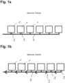
- the internal combustion engine can be an engine with a plurality of separate cylinder heads 1 .
- the cylinder heads each have a cooling system which must be vented via a vent opening 9 arranged on the cylinder head.
- a ventilation system is also from the U.S. 3,646,919 A known.
- pamphlet WO 2004/076022 A1 also shows a ventilation system for the cylinder heads of an internal combustion engine, all the ventilation openings of the cylinders being arranged in series in one branch of the ventilation system.
- the cooler is vented with a second, parallel line.
- pamphlet JP 01142212A shows an internal combustion engine with a common cylinder head bank for all cylinders.
- a ventilation opening for the cooling system is provided at a front end and at a rear end of the cylinder head bank.
- the ventilation openings are each connected to a branch of the ventilation line via valves, the two branches being brought together and connected to a third branch which leads to the tank. This is intended to ensure ventilation even when the internal combustion engine is arranged in an inclined position.
- pamphlets FR 2 388 133 A1 , EP 2 789 824 A1 , U.S. 3,646,919 A and U.S. 2,841,127 A show other cooling systems for combustion engines.
- the inventors of the present invention have recognized that with a ventilation system according to U.S. 3,646,919 A proper quick venting is problematic.
- the present invention comprises an internal combustion engine with a ventilation system for venting the cooling system of a plurality of separate cylinder heads of the internal combustion engine or for venting a plurality of areas of the cooling system assigned to the individual cylinders of a connected cylinder head bank of the internal combustion engine, with a ventilation line which ventilation openings the cooling system with a tank and/or the environment, the vent line having a first branch which connects at least two vent openings in series.
- the invention is characterized in that the ventilation line has at least one second line, which is arranged parallel to the first line in the ventilation line and connects at least two ventilation openings in series. This means that the first and the second line are not connected in series, but the air flows in the first and the second line run separately from one another. The air streams from the first and the second line are then preferably brought together at one point in the ventilation system.
- the second parallel branch of the ventilation line enables improved ventilation of the cooling system of the cylinder heads, in particular improved quick ventilation, as is necessary when the cooling system of the cylinder heads is filled for the first time.
- the inventors of the present invention have recognized that in the case of a ventilation line with only one branch, which connects all cylinder heads in series, a flow reversal can occur in the area of those ventilation openings which, viewed in the direction of flow, are at the beginning of the ventilation line, see area 3 in Fig. 1b , which shows through the arrows the direction of flow within the ventilation system according to the prior art.
- the large amount of air that flows downstream through the ventilation openings arranged there into the ventilation line pushes so hard backwards that no air escapes from individual ventilation openings at the beginning of the ventilation line, and sometimes even air is pushed into the respective component or area via the ventilation openings.
- a considerably lower bleed or filling speed would have been necessary.
- the two parallel strands of the ventilation line enable a significantly improved rapid ventilation of the cylinder heads, since there is no longer a flow reversal and air flows out equally from all ventilation openings.
- the second branch of the ventilation line also connects at least two ventilation openings in series, i.e. at least two ventilation openings are also arranged one behind the other in the second branch.
- the first leg and the second leg each connect at least three vents in series.
- the ventilation line further comprises at least one third line, which is connected to the first and the second line and connects them together with the tank and/or the environment.
- the first and second legs are therefore joined at a point in the vent line and the air from the first and second legs flows from this point together via the third leg to the tank or atmosphere.
- the third leg does not necessarily have to be in the form of a separate tubular element from the first and second legs.
- the first branch can open into the second branch, which from this point forms the third branch, or vice versa.
- the three strands are preferably formed by separate tubular elements which are connected to one another.
- no ventilation openings are arranged in the third line, i.e. it only serves to evacuate the air from the ventilation openings, which are arranged in the first and in the second line.
- the first and second legs preferably each have a first end communicating with a first vent opening in that leg and a second end, the second ends of the first and second legs communicating with each other.
- the strands are preferably designed in such a way that air can flow from the first vent opening in only one direction through the respective strand to a subsequent vent opening or to the second end, i.e. the first end is closed except for the connection with the first vent opening.
- the first and the second parallel branch of the ventilation line are connected to the third branch in the area of a ventilation opening. This results in a particularly simple structure.
- connection of at least one of the strands to the ventilation opening can simultaneously serve to connect the strands to one another and to the third strand.
- a connector element is provided, which serves to connect the three strands to one another and to connect to the ventilation opening.
- the ventilation line is an internal ventilation line which runs, for example, within a cylinder head bank for the internal connection of the ventilation openings of the respective cylinder head areas.
- the vent line is an external vent line which is connected via Connector elements is connected to the ventilation openings of the internal combustion engine.
- the ventilation line can consist of one or more tube elements which are connected to the ventilation openings via connector elements.
- the strands particularly preferably consist of tubular elements which are connected not only to the ventilation openings but also to one another through the connector elements.
- At least one connector element is designed as a connector screw, which has an axial bore that is in fluid communication with the vent opening, and at least one radial bore that is connected to the axial bore, the connection with a branch of the ventilation line via a clamp, which encompasses the circumference of the connector screw in the area of the radial bore, and to which the ventilation line is connected. All connector elements are preferably designed as such connector screws.
- the connector screw or connector screws can be screwed to ventilation openings provided in the housing of the internal combustion engine.
- At least one connector element has at least two radial bores that are spaced apart in the axial direction and that each interact with a clamp.
- two tube sections can be connected one above the other in the axial direction with the connector screw.
- a first clamp is preferably associated with the first parallel strand and a second clamp is associated with the second parallel strand in order to connect them via the connector screw.
- one of the two clamps has a further connection for connection to the third branch of the ventilation line.
- the connection of the first, the second and the third line is therefore made via two clamps.
- the connector element is used to connect to the last vent opening in the flow direction of the first and second line, which is arranged in both lines by the connector element.
- At least one connector element is designed as a connector screw, which has an axial bore which is in fluid communication with the vent opening, and at least one radial bore which is connected to the axial bore, the connection being made with a Line of the vent line via a clamp, which includes the circumference of the connector screw in the radial bore, and to which all three strands of the vent line are connected.
- annular space is formed between an inner surface of the clamp and an outer surface of the connector screw, which also connects the ventilation line connected to the clamp to the radial bore in the connector screw if it is not in the same radial angular position on the Connector screw is arranged as the radial bore, and / or which connects several connected to the clamp strands of the vent line with each other.
- the annular space is preferably formed by a corresponding recess or a correspondingly curved shape in an inner surface of the clamp.
- the vents are arranged in a row along the length of the engine, with the first and second runs each connecting a group of vents in series, the first and second runs having the same flow direction with respect to those arranged in a row have ventilation openings.
- the connection of the vent openings within the strands is therefore in the same direction as would be the case with only a single continuous strand.
- the ventilation openings can be the ventilation openings of the cylinder heads of a cylinder bank.
- the first line preferably has a first section, which connects the first group of ventilation openings to one another, and a second section, which serves to connect the first section to the second and/or third line.
- the second section can be routed past the second group of ventilation openings.
- the second section is in connection with this and the third line in the region of the last ventilation opening of the second line in the direction of flow.
- a fixing element which fixes the first and/or the second line in a region between two ventilation openings on the housing of the internal combustion engine.
- the fixing element preferably fixes the second section of the first strand to the housing of the internal combustion engine, since this is longer than the other sections. Furthermore, the fixing element can fix the first and the second line together on the housing of the internal combustion engine.
- the ventilation line does not include any further branches apart from the first, second and third branch.
- the ventilation line can also have further strands which are connected to the first, second and/or third strand in a tree-shaped and/or star-shaped manner.
- the ventilation system preferably connects the cooling system of the cylinder heads of the internal combustion engine to the tank and/or the environment permanently and/or without interposed valves.
- the venting system is used to vent areas of the cooling system of a one-piece cylinder head bank of the internal combustion engine that are associated with the individual cylinders.
- the internal combustion engine has a separate cylinder head with at least one ventilation opening for each cylinder.
- the ventilation line is preferably designed as an external ventilation line which connects the ventilation openings to the tank and/or the environment.
- all cylinder heads of a cylinder bank are connected to the tank and/or the environment via the first and the second line of the ventilation line. If a further cylinder bank is provided, it can have a further ventilation system according to the invention.
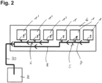
- FIG. 2 shows a schematic representation of an embodiment of the internal combustion engine 4 according to the invention with a ventilation system according to the invention.
- the internal combustion engine 4 comprises a plurality of components or areas 1 and 1', each of which has a ventilation opening 9 and 9', respectively. Furthermore, a ventilation line is provided, which connects the ventilation openings 9 and 9' to a tank 8.
- the tank 8 can be an expansion tank. Alternatively or additionally, the ventilation line could also connect the ventilation openings 9 and 9' to the environment.
- the ventilation line has two parallel branches 5 and 6, with the first branch 5 serially connecting the ventilation openings 9 of a first subgroup of components and/or areas 1, and the second branch 6 connecting the ventilation openings 9' of a second subgroup of components or areas 1 ' serially connected. Furthermore, the ventilation line has a third branch 30, which is connected in series with the first branch 5 and the second branch 6 and connects them together with the tank 8 or the environment.
- the components and/or areas 1 or 1′ or their ventilation openings 9 or 9′ on the internal combustion engine 4 are arranged in a row.
- the first branch 5 and the second branch 6 connect the ventilation openings 9 and 9′ to the tank 8 or the environment in such a way that the same direction of flow relative to the internal combustion engine is present in both branches.
- the first strand 5 therefore has a first area 7, which connects the ventilation openings 9 to one another in series, and a second partial area 8, which geometrically bypasses the ventilation openings 9' of the second group of components and/or areas runs largely parallel to the second strand 6.
- connection between the first and the second strand can be made at one end of the components and/or regions of the internal combustion engine 9 and 9′ arranged in a row.
- the ventilation system according to the invention can therefore be attached to the internal combustion engine in the same way as a ventilation system according to the prior art, and in particular the same configuration of the third line 30 can be used.
- the first and the second strand unite in the area of the last vent opening 9' of the second subgroup of components and/or areas 1', or upstream of this. From there, the air from all ventilation openings flows together through the third line to the tank 8 or to the environment.
- the components and/or areas 1 and 1′ of the internal combustion engine are separate cylinder heads of a cylinder bank of the internal combustion engine. These each have a cooling system with its own ventilation opening, since with separate cylinder heads a central ventilation opening cannot be used for all cylinder heads.
- venting system now allows the engine to be filled quickly, since all cylinder heads are now vented quickly in the same way.
- the components and/or areas 1 and 1′ are also the areas of the cooling system assigned to the individual cylinders of a continuous, in particular one-piece cylinder head bank of an internal combustion engine. Even with such a connected bank of cylinder heads, the individual cylinder heads or their cooling areas can each have separate ventilation openings, which can be better ventilated via a ventilation system according to the invention.
- the ventilation system according to the invention can also be designed as an internal line system or partially internal line system of the cylinder head bank.
- the ventilation system is preferably designed as an external ventilation system, i.e. equipped with external ventilation lines which are connected to the ventilation openings of the components and/or areas via connector elements.
- the ventilation system according to the invention can be used both in in-line engines and in V-engines.
- the ventilation system is preferably designed in such a way that all the cylinder heads of a cylinder bank are vented via the first and the second line.
- both banks of cylinders preferably each have a ventilation system according to the invention with a first and a second parallel line. If necessary, the third strands can be brought together again. However, they can also be routed separately to a tank and/or the environment.
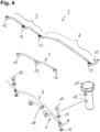
- the embodiment shown is an external ventilation system with external ventilation lines, which are connected via connector elements 10 to 13 to the ventilation openings, which are preferably provided in the housing of the internal combustion engine.
- the ventilation system is used to ventilate the cylinder heads of a cylinder bank.
- the individual strands of the ventilation line consist of pipe sections which connect the ventilation openings to one another and to the tank and/or the environment.
- the connector elements 10 to 13 are used to connect the pipe sections to one another and to the ventilation openings.
- the connector element 11 via which the second line 6 is connected to the last vent opening viewed in the direction of flow, is also used to connect the first line 5 and the third line 30.
- the first line 5 and the second line 6 therefore unite in the area of the last vent opening to the common third line 30 of the vent line.
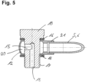
- the connector elements are designed as connector screws 10 and 11 with associated clamps 12 and 13, it being possible for the connector screws to be screwed into the housing of the internal combustion engine or the corresponding component. These have a thread 17 for this purpose.
- the fluidic contacting of the ventilation openings takes place through an axial bore 18.
- This is in fluid communication with at least one radial bore 15.
- the connector screw is encompassed by a clip 12 or 13, which serves to connect the radial bore 15 to the pipe sections of the ventilation line.
- the clamps 12 and 13 each have at least one connecting piece 21 for connection to a pipe section of the ventilation line, in particular a pipe sleeve.
- the clamps each have an annular space 20 which is formed between the peripheral wall of the connector screw and the inner wall of the respective clamp and thus surrounds the connector screw in the form of a ring.
- This configuration has the advantage that the fluidic contact between the respective pipe section and the radial bore 15 is independent of the radial position of the connection area 21 with the pipe section relative to the radial direction of the bore 15 is possible. Furthermore, the ring-shaped area 20 allows two pipe sections to be connected to one another.
- the clamps 13 each have a connection area 21 for connection to a pipe section at two different angular positions. Therefore, clamps 13 with two connecting areas 21 are used within the individual strands, which at the same time serve to connect two pipe sections, which are arranged in series within the strand, and the respective ventilation opening.
- the connection to the first vent opening in the direction of flow takes place in each line via a rapid 12 with only one connecting element 21 for the pipe section leading from this vent opening to the next vent opening.
- sealing washers 16 are used, one of which is arranged above and below the clamp and thus between the head of the connector screw and the clamp and between the clamp and the housing for one seal.
- the sealing disks can be metal disks with an integrated sealing arrangement.
- Such a connector screw with a clamp is in figure 5 shown.
- the connector screw 11 which is used to connect the two parallel strands 5 and 6 to the common third strand 30, is in 6 shown.
- the clamps and the connector screw correspond in structure to the in figure 5 shown configuration.
- the connector screw 11 has a radial bore 15 on two axial planes, with a first radial bore interacting with a first clamp 12 and a second radial bore interacting with a further clamp 13 .
- Two clamps are therefore arranged one above the other on the connector screw in the axial direction.
- the clamp 13 is arranged in the first line and is also used for the connection to the third line 30.
- the second clamp 12, on the other hand, is arranged in the second line 6 and therefore only has a connection area to this line.
- a fixing element 14 is also provided in the exemplary embodiment, which fixes this second area 8 to the housing of the internal combustion engine.
- the fixing element 14 is designed in such a way that it fixes both the second area 8 of the first strand 5 and a tube section of the second strand 6 to the housing.
- the fixing element 14 is designed in such a way that it fixes both the second area 8 of the first strand 5 and a tube section of the second strand 6 to the housing.
Landscapes
- Engineering & Computer Science (AREA)
- Chemical & Material Sciences (AREA)
- Combustion & Propulsion (AREA)
- Mechanical Engineering (AREA)
- General Engineering & Computer Science (AREA)
- Cylinder Crankcases Of Internal Combustion Engines (AREA)
- Lubrication Details And Ventilation Of Internal Combustion Engines (AREA)
Claims (13)
- Moteur à combustion interne avec un système de purge d'air pour purger l'air du système de refroidissement d'une multitude de culasses (1, 1') séparées du moteur à combustion interne (4) ou pour purger l'air d'une multitude de zones, associées aux divers cylindres, du système de refroidissement d'une banque de culasses contiguë du moteur à combustion interne, avec une conduite de purge d'air, laquelle relie des orifices de purge d'air (9) du système de refroidissement à un réservoir (28) et/ou à l'environnement, dans lequel la conduite de purge d'air présente une première branche (5), laquelle relie en série au moins deux orifices de purge d'air (9),
caractérisé en ce que
la conduite de purge d'air présente au moins une deuxième branche (6), laquelle est disposée dans la conduite de purge d'air de manière parallèle par rapport à la première branche (5) et relie en série au moins deux orifices de purge d'air (9'). - Moteur à combustion interne selon la revendication 1, dans lequel la conduite de purge d'air présente au moins une troisième branche (30), laquelle est reliée à la première et à la deuxième branche (5, 6) et relie celles-ci conjointement au réservoir (28) et/ou à l'environnement.
- Moteur à combustion interne selon la revendication 2, dans lequel la première et la deuxième branche parallèle (5, 6) de la conduite de purge d'air sont en communication, dans la zone d'un orifice de purge d'air, avec la troisième branche (30), en particulier par un élément de connecteur (11), lequel sert à relier les trois branches entre elles et se destine à être relié à l'orifice de purge d'air.
- Moteur à combustion interne selon l'une quelconque des revendications précédentes, dans lequel la conduite de purge d'air est une conduite de purge d'air externe, laquelle est en communication avec les orifices de purge d'air par l'intermédiaire d'éléments de connecteur (10, 11), dans lequel de manière préférée au moins un élément de connecteur (10, 11) est exécuté en tant qu'une vise de connecteur, laquelle présente un alésage axial (18), lequel est en communication fluidique avec l'orifice de purge d'air, ainsi qu'au moins un alésage radial (15), lequel est relié à l'alésage axial, dans lequel la liaison à une branche de la conduite de purge d'air se fait par l'intermédiaire d'un collier (12), lequel encadre la périphérie de la vis de connecteur dans la zone de l'alésage radial (15) et auquel la conduite de purge d'air est raccordée.
- Moteur à combustion interne selon la revendication 5, dans lequel au moins un élément de connecteur (11) présente au moins deux alésages radiaux (15) tenus à distance dans une direction axiale, lesquels coopèrent respectivement avec un collier (12, 13), dans lequel de manière préférée un premier collier (13) est associé à la première branche (5) parallèle et un deuxième collier (12) est associé à la deuxième branche (6) parallèle pour relier celles-ci par l'intermédiaire de la vis de connecteur (11), dans lequel un des deux colliers présente de manière davantage préférée un autre raccord destiné à être raccordé à la troisième branche (30) de la conduite de purge d'air, et/ou dans lequel un collier est en communication avec les trois branches de la conduite de purge d'air.
- Moteur à combustion interne selon la revendication 4 ou 5, dans lequel est formé entre une surface intérieure du collier (12, 13) et une surface extérieure de la vis de connecteur (11), un espace annulaire (20), lequel relie la conduite de purge d'air (5, 6, 30) raccordée au collier également alors à l'alésage radial (15) dans la vis de connecteur lorsque celui-ci n'est pas disposé dans la même position angulaire radiale sur la vis de connecteur que l'alésage radial (15), et/ou lequel espace annulaire relie plusieurs branches (5, 30), raccordées au collier (13), de la conduite de purge d'air entre elles.
- Moteur à combustion interne selon l'une quelconque des revendications précédentes, dans lequel les orifices de purge d'air (9, 9') sont disposés le long du moteur (4) en une rangée, dans lequel la première et la deuxième branche (5, 6) relient en série respectivement un groupe d'orifices de purge d'air (9, 9') les uns aux autres, dans lequel la première et la deuxième branche (5, 6) présentent la même direction d'écoulement par rapport aux orifices de purge d'air (9, 9') disposés en une rangée, dans lequel de manière préférée la première branche (5) présente une première section (7), laquelle relie le premier groupe d'orifices de purge d'air (9) les uns aux autres, et une deuxième section (8), laquelle sert à relier la première section (7) à la deuxième et/ou à la troisième branche (6, 30), dans lequel la deuxième section (8) est guidée de manière préférée le long du deuxième groupe d'orifices de purge d'air (9'), et est en communication, de manière davantage préférée dans la zone du dernier orifice de purge d'air (9') dans la direction d'écoulement de la deuxième branche (6) à celle-ci et à la troisième branche (30).
- Moteur à combustion interne selon l'une quelconque des revendications précédentes, avec un élément de blocage (14), lequel bloque la première et/ou la deuxième branche (5, 6) dans une zone entre deux orifices d'aération sur le carter du moteur à combustion interne, dans lequel l'élément de blocage (14) bloque de manière préférée la deuxième section (8) de la première branche (5) sur le carter du moteur à combustion interne et/ou bloque la première et la deuxième branche (5, 6) conjointement sur le carter du moteur à combustion interne.
- Moteur à combustion interne selon l'une quelconque des revendications précédentes, avec d'autres branches de la conduite de purge d'air, lesquelles sont en communication en forme d'arbre et/ou en forme d'étoile avec la première, la deuxième et/ou la troisième branche (5, 6, 30).
- Moteur à combustion interne selon l'une quelconque des revendications précédentes, dans lequel le système de purge d'air relie le système de refroidissement en permanence et/ou sans soupapes intercalées au réservoir et/ou à l'environnement.
- Moteur à combustion interne selon l'une quelconque des revendications précédentes, dans lequel le système de purge d'air sert à purger l'air des zones, associées à divers cylindres, du système de refroidissement d'une banque de culasses d'un seul tenant du moteur à combustion interne.
- Moteur à combustion interne selon l'une quelconque des revendications 1 à 10, dans lequel le moteur à combustion interne présente pour chaque cylindre une culasse (1, 1') séparée avec au moins un orifice de purge d'air.
- Moteur à combustion interne selon la revendication 11 ou 12, dans lequel toutes les culasses (1, 1') d'une banque de cylindres sont en communication avec le réservoir et/ou l'environnement par l'intermédiaire de la première et de la deuxième branche (5, 6) de la conduite de purge d'air.
Applications Claiming Priority (1)
| Application Number | Priority Date | Filing Date | Title |
|---|---|---|---|
| CH00444/18A CH714873A1 (de) | 2018-04-05 | 2018-04-05 | Verbrennungsmotor mit einem Entlüftungssystem. |
Publications (2)
| Publication Number | Publication Date |
|---|---|
| EP3550119A1 EP3550119A1 (fr) | 2019-10-09 |
| EP3550119B1 true EP3550119B1 (fr) | 2023-04-26 |
Family
ID=65904336
Family Applications (1)
| Application Number | Title | Priority Date | Filing Date |
|---|---|---|---|
| EP19164618.1A Active EP3550119B1 (fr) | 2018-04-05 | 2019-03-22 | Moteur à combustion interne doté d'un système de purge d'air |
Country Status (2)
| Country | Link |
|---|---|
| EP (1) | EP3550119B1 (fr) |
| CH (1) | CH714873A1 (fr) |
Family Cites Families (9)
| Publication number | Priority date | Publication date | Assignee | Title |
|---|---|---|---|---|
| US2841127A (en) * | 1955-02-16 | 1958-07-01 | White Motor Co | Cooling system |
| DE1937146A1 (de) * | 1969-07-22 | 1971-02-04 | Daimler Benz Ag | Kuehlwasserfuehrung bei Hubkolbenbrennkraftmaschinen |
| FR2388133A1 (fr) * | 1977-04-19 | 1978-11-17 | Renault | Perfectionnement aux circuits de refroidissement de moteurs a combustion interne |
| DE19948160B4 (de) * | 1999-10-07 | 2010-07-15 | Wilhelm Kuhn | Kühlvorrichtung für eine flüssigkeitsgekühlte Brennkraftmaschine eines Kraftfahrzeuges |
| SE524916C2 (sv) * | 2003-02-27 | 2004-10-19 | Scania Cv Abp | Anordning för att separera gas från ett vätskeformigt medium |
| GB0426647D0 (en) * | 2004-12-04 | 2005-01-05 | Ford Global Tech Llc | An engine cooling system |
| DE102006019880A1 (de) * | 2006-04-28 | 2007-10-31 | Audi Ag | Motorgehäusedeckel eines Verbrennungsmotors mit Entlüftungssystem |
| DE102007027719B4 (de) * | 2007-06-15 | 2015-05-13 | Audi Ag | Brennkraftmaschine mit einem Heizungskreislauf und einem Kühlkreislauf |
| FR3004489B1 (fr) * | 2013-04-11 | 2017-04-28 | Bontaz Centre R & D | Dispositif de refroidissement pour moteur a combustion interne a encombrement reduit et procede de fabrication d'un tel dispositif |
-
2018
- 2018-04-05 CH CH00444/18A patent/CH714873A1/de not_active Application Discontinuation
-
2019
- 2019-03-22 EP EP19164618.1A patent/EP3550119B1/fr active Active
Also Published As
| Publication number | Publication date |
|---|---|
| CH714873A1 (de) | 2019-10-15 |
| EP3550119A1 (fr) | 2019-10-09 |
Similar Documents
| Publication | Publication Date | Title |
|---|---|---|
| DE102017207797B4 (de) | Klima-service-gerät für eine fahrzeugklimaanlage | |
| EP1852295A1 (fr) | Système d'échappement | |
| EP1676989B1 (fr) | Moteur à combustion interne avec un dispositif de refroidissement de piston | |
| EP3498359B1 (fr) | Élément filtrant et dispositif filtrant correspondant | |
| DE69405846T2 (de) | Lenksäuleneinheit, insbesondere für ein Kraftfahrzeug | |
| EP3550119B1 (fr) | Moteur à combustion interne doté d'un système de purge d'air | |
| EP3514434A1 (fr) | Collier | |
| DE10247958A1 (de) | Kraftstoff-Einspritzvorrichtung für eine Brennkraftmaschine | |
| DE102022105548A1 (de) | Luftleitvorrichtung einer Kraftfahrzeugkarosserie eines Kraftfahrzeugs | |
| DE102013011106A1 (de) | Abgasturbolader | |
| DE102004056295B4 (de) | Ölversorgungsvorrichtung für ein Flugzeugtriebwerk | |
| DE102014018623A1 (de) | Verbindungsanordnung eines Abgaskrümmers an einem Turbinengehäuse | |
| EP3123034B1 (fr) | Système de connexion d'une tige de piston | |
| DE102012020243B4 (de) | Trägergehäuse für eine Abgasturbolader-Anordnung, Abgasturbolader-Anordnung und Verbrennungsmotor | |
| DE102010054231A1 (de) | Anordnung eines Druckbehälters an einem Fahrzeug | |
| EP1719925B1 (fr) | Système de fixation d'éléments de liaison allongés et transversalement rigides | |
| EP3101318B1 (fr) | Module de vanne | |
| EP2776723B1 (fr) | Connexion axiale | |
| DE102018112448A1 (de) | Werkzeug zur Halterung der Hochdruckwelle eines Flugzeugtriebwerks | |
| DE102021131269A1 (de) | Monolithische Klemmvorrichtung | |
| DE102016001705A1 (de) | Fixierelement und Schraubverbindung | |
| DE102016014214A1 (de) | Montagewerkzeug | |
| DE202023106491U1 (de) | Hebelanbindung einer Leitschaufelverstellung für eine Strömungsmaschine | |
| DE102016215455A1 (de) | Temperierbare Leitung insbesondere für ein Reduktionsmittel einer Abgasnachbehandlungsvorrichtung einer Kfz-Brennkraftmaschine | |
| DE102016101704B4 (de) | Antriebssystem für ein Fahrzeug |
Legal Events
| Date | Code | Title | Description |
|---|---|---|---|
| PUAI | Public reference made under article 153(3) epc to a published international application that has entered the european phase |
Free format text: ORIGINAL CODE: 0009012 |
|
| STAA | Information on the status of an ep patent application or granted ep patent |
Free format text: STATUS: THE APPLICATION HAS BEEN PUBLISHED |
|
| AK | Designated contracting states |
Kind code of ref document: A1 Designated state(s): AL AT BE BG CH CY CZ DE DK EE ES FI FR GB GR HR HU IE IS IT LI LT LU LV MC MK MT NL NO PL PT RO RS SE SI SK SM TR |
|
| AX | Request for extension of the european patent |
Extension state: BA ME |
|
| STAA | Information on the status of an ep patent application or granted ep patent |
Free format text: STATUS: REQUEST FOR EXAMINATION WAS MADE |
|
| 17P | Request for examination filed |
Effective date: 20200324 |
|
| RAP1 | Party data changed (applicant data changed or rights of an application transferred) |
Owner name: LIEBHERR MACHINES BULLE SA |
|
| STAA | Information on the status of an ep patent application or granted ep patent |
Free format text: STATUS: EXAMINATION IS IN PROGRESS |
|
| 17Q | First examination report despatched |
Effective date: 20210805 |
|
| GRAP | Despatch of communication of intention to grant a patent |
Free format text: ORIGINAL CODE: EPIDOSNIGR1 |
|
| STAA | Information on the status of an ep patent application or granted ep patent |
Free format text: STATUS: GRANT OF PATENT IS INTENDED |
|
| INTG | Intention to grant announced |
Effective date: 20230215 |
|
| GRAS | Grant fee paid |
Free format text: ORIGINAL CODE: EPIDOSNIGR3 |
|
| GRAA | (expected) grant |
Free format text: ORIGINAL CODE: 0009210 |
|
| STAA | Information on the status of an ep patent application or granted ep patent |
Free format text: STATUS: THE PATENT HAS BEEN GRANTED |
|
| AK | Designated contracting states |
Kind code of ref document: B1 Designated state(s): AL AT BE BG CH CY CZ DE DK EE ES FI FR GB GR HR HU IE IS IT LI LT LU LV MC MK MT NL NO PL PT RO RS SE SI SK SM TR |
|
| REG | Reference to a national code |
Ref country code: GB Ref legal event code: FG4D Free format text: NOT ENGLISH |
|
| REG | Reference to a national code |
Ref country code: CH Ref legal event code: EP |
|
| REG | Reference to a national code |
Ref country code: DE Ref legal event code: R096 Ref document number: 502019007534 Country of ref document: DE |
|
| REG | Reference to a national code |
Ref country code: AT Ref legal event code: REF Ref document number: 1562969 Country of ref document: AT Kind code of ref document: T Effective date: 20230515 |
|
| REG | Reference to a national code |
Ref country code: IE Ref legal event code: FG4D Free format text: LANGUAGE OF EP DOCUMENT: GERMAN |
|
| REG | Reference to a national code |
Ref country code: SE Ref legal event code: TRGR |
|
| REG | Reference to a national code |
Ref country code: LT Ref legal event code: MG9D |
|
| REG | Reference to a national code |
Ref country code: NL Ref legal event code: MP Effective date: 20230426 |
|
| PG25 | Lapsed in a contracting state [announced via postgrant information from national office to epo] |
Ref country code: NL Free format text: LAPSE BECAUSE OF FAILURE TO SUBMIT A TRANSLATION OF THE DESCRIPTION OR TO PAY THE FEE WITHIN THE PRESCRIBED TIME-LIMIT Effective date: 20230426 |
|
| PG25 | Lapsed in a contracting state [announced via postgrant information from national office to epo] |
Ref country code: PT Free format text: LAPSE BECAUSE OF FAILURE TO SUBMIT A TRANSLATION OF THE DESCRIPTION OR TO PAY THE FEE WITHIN THE PRESCRIBED TIME-LIMIT Effective date: 20230828 Ref country code: NO Free format text: LAPSE BECAUSE OF FAILURE TO SUBMIT A TRANSLATION OF THE DESCRIPTION OR TO PAY THE FEE WITHIN THE PRESCRIBED TIME-LIMIT Effective date: 20230726 Ref country code: ES Free format text: LAPSE BECAUSE OF FAILURE TO SUBMIT A TRANSLATION OF THE DESCRIPTION OR TO PAY THE FEE WITHIN THE PRESCRIBED TIME-LIMIT Effective date: 20230426 |
|
| PG25 | Lapsed in a contracting state [announced via postgrant information from national office to epo] |
Ref country code: RS Free format text: LAPSE BECAUSE OF FAILURE TO SUBMIT A TRANSLATION OF THE DESCRIPTION OR TO PAY THE FEE WITHIN THE PRESCRIBED TIME-LIMIT Effective date: 20230426 Ref country code: PL Free format text: LAPSE BECAUSE OF FAILURE TO SUBMIT A TRANSLATION OF THE DESCRIPTION OR TO PAY THE FEE WITHIN THE PRESCRIBED TIME-LIMIT Effective date: 20230426 Ref country code: LV Free format text: LAPSE BECAUSE OF FAILURE TO SUBMIT A TRANSLATION OF THE DESCRIPTION OR TO PAY THE FEE WITHIN THE PRESCRIBED TIME-LIMIT Effective date: 20230426 Ref country code: LT Free format text: LAPSE BECAUSE OF FAILURE TO SUBMIT A TRANSLATION OF THE DESCRIPTION OR TO PAY THE FEE WITHIN THE PRESCRIBED TIME-LIMIT Effective date: 20230426 Ref country code: IS Free format text: LAPSE BECAUSE OF FAILURE TO SUBMIT A TRANSLATION OF THE DESCRIPTION OR TO PAY THE FEE WITHIN THE PRESCRIBED TIME-LIMIT Effective date: 20230826 Ref country code: HR Free format text: LAPSE BECAUSE OF FAILURE TO SUBMIT A TRANSLATION OF THE DESCRIPTION OR TO PAY THE FEE WITHIN THE PRESCRIBED TIME-LIMIT Effective date: 20230426 Ref country code: GR Free format text: LAPSE BECAUSE OF FAILURE TO SUBMIT A TRANSLATION OF THE DESCRIPTION OR TO PAY THE FEE WITHIN THE PRESCRIBED TIME-LIMIT Effective date: 20230727 |
|
| PG25 | Lapsed in a contracting state [announced via postgrant information from national office to epo] |
Ref country code: FI Free format text: LAPSE BECAUSE OF FAILURE TO SUBMIT A TRANSLATION OF THE DESCRIPTION OR TO PAY THE FEE WITHIN THE PRESCRIBED TIME-LIMIT Effective date: 20230426 |
|
| PG25 | Lapsed in a contracting state [announced via postgrant information from national office to epo] |
Ref country code: SK Free format text: LAPSE BECAUSE OF FAILURE TO SUBMIT A TRANSLATION OF THE DESCRIPTION OR TO PAY THE FEE WITHIN THE PRESCRIBED TIME-LIMIT Effective date: 20230426 |
|
| REG | Reference to a national code |
Ref country code: DE Ref legal event code: R097 Ref document number: 502019007534 Country of ref document: DE |
|
| PG25 | Lapsed in a contracting state [announced via postgrant information from national office to epo] |
Ref country code: SM Free format text: LAPSE BECAUSE OF FAILURE TO SUBMIT A TRANSLATION OF THE DESCRIPTION OR TO PAY THE FEE WITHIN THE PRESCRIBED TIME-LIMIT Effective date: 20230426 Ref country code: SK Free format text: LAPSE BECAUSE OF FAILURE TO SUBMIT A TRANSLATION OF THE DESCRIPTION OR TO PAY THE FEE WITHIN THE PRESCRIBED TIME-LIMIT Effective date: 20230426 Ref country code: RO Free format text: LAPSE BECAUSE OF FAILURE TO SUBMIT A TRANSLATION OF THE DESCRIPTION OR TO PAY THE FEE WITHIN THE PRESCRIBED TIME-LIMIT Effective date: 20230426 Ref country code: EE Free format text: LAPSE BECAUSE OF FAILURE TO SUBMIT A TRANSLATION OF THE DESCRIPTION OR TO PAY THE FEE WITHIN THE PRESCRIBED TIME-LIMIT Effective date: 20230426 Ref country code: DK Free format text: LAPSE BECAUSE OF FAILURE TO SUBMIT A TRANSLATION OF THE DESCRIPTION OR TO PAY THE FEE WITHIN THE PRESCRIBED TIME-LIMIT Effective date: 20230426 Ref country code: CZ Free format text: LAPSE BECAUSE OF FAILURE TO SUBMIT A TRANSLATION OF THE DESCRIPTION OR TO PAY THE FEE WITHIN THE PRESCRIBED TIME-LIMIT Effective date: 20230426 |
|
| PLBE | No opposition filed within time limit |
Free format text: ORIGINAL CODE: 0009261 |
|
| STAA | Information on the status of an ep patent application or granted ep patent |
Free format text: STATUS: NO OPPOSITION FILED WITHIN TIME LIMIT |
|
| 26N | No opposition filed |
Effective date: 20240129 |
|
| PG25 | Lapsed in a contracting state [announced via postgrant information from national office to epo] |
Ref country code: SI Free format text: LAPSE BECAUSE OF FAILURE TO SUBMIT A TRANSLATION OF THE DESCRIPTION OR TO PAY THE FEE WITHIN THE PRESCRIBED TIME-LIMIT Effective date: 20230426 |
|
| PG25 | Lapsed in a contracting state [announced via postgrant information from national office to epo] |
Ref country code: SI Free format text: LAPSE BECAUSE OF FAILURE TO SUBMIT A TRANSLATION OF THE DESCRIPTION OR TO PAY THE FEE WITHIN THE PRESCRIBED TIME-LIMIT Effective date: 20230426 |
|
| REG | Reference to a national code |
Ref country code: CH Ref legal event code: PL |
|
| PG25 | Lapsed in a contracting state [announced via postgrant information from national office to epo] |
Ref country code: BG Free format text: LAPSE BECAUSE OF FAILURE TO SUBMIT A TRANSLATION OF THE DESCRIPTION OR TO PAY THE FEE WITHIN THE PRESCRIBED TIME-LIMIT Effective date: 20230426 |
|
| PG25 | Lapsed in a contracting state [announced via postgrant information from national office to epo] |
Ref country code: LU Free format text: LAPSE BECAUSE OF NON-PAYMENT OF DUE FEES Effective date: 20240322 |
|
| PG25 | Lapsed in a contracting state [announced via postgrant information from national office to epo] |
Ref country code: MC Free format text: LAPSE BECAUSE OF FAILURE TO SUBMIT A TRANSLATION OF THE DESCRIPTION OR TO PAY THE FEE WITHIN THE PRESCRIBED TIME-LIMIT Effective date: 20230426 |
|
| PG25 | Lapsed in a contracting state [announced via postgrant information from national office to epo] |
Ref country code: MC Free format text: LAPSE BECAUSE OF FAILURE TO SUBMIT A TRANSLATION OF THE DESCRIPTION OR TO PAY THE FEE WITHIN THE PRESCRIBED TIME-LIMIT Effective date: 20230426 Ref country code: LU Free format text: LAPSE BECAUSE OF NON-PAYMENT OF DUE FEES Effective date: 20240322 Ref country code: BG Free format text: LAPSE BECAUSE OF FAILURE TO SUBMIT A TRANSLATION OF THE DESCRIPTION OR TO PAY THE FEE WITHIN THE PRESCRIBED TIME-LIMIT Effective date: 20230426 |
|
| REG | Reference to a national code |
Ref country code: BE Ref legal event code: MM Effective date: 20240331 |
|
| PG25 | Lapsed in a contracting state [announced via postgrant information from national office to epo] |
Ref country code: BE Free format text: LAPSE BECAUSE OF NON-PAYMENT OF DUE FEES Effective date: 20240331 |
|
| PG25 | Lapsed in a contracting state [announced via postgrant information from national office to epo] |
Ref country code: IE Free format text: LAPSE BECAUSE OF NON-PAYMENT OF DUE FEES Effective date: 20240322 |
|
| PG25 | Lapsed in a contracting state [announced via postgrant information from national office to epo] |
Ref country code: IE Free format text: LAPSE BECAUSE OF NON-PAYMENT OF DUE FEES Effective date: 20240322 Ref country code: BE Free format text: LAPSE BECAUSE OF NON-PAYMENT OF DUE FEES Effective date: 20240331 Ref country code: CH Free format text: LAPSE BECAUSE OF NON-PAYMENT OF DUE FEES Effective date: 20240331 |
|
| PGFP | Annual fee paid to national office [announced via postgrant information from national office to epo] |
Ref country code: SE Payment date: 20250307 Year of fee payment: 7 |
|
| PGFP | Annual fee paid to national office [announced via postgrant information from national office to epo] |
Ref country code: DE Payment date: 20250331 Year of fee payment: 7 |
|
| PGFP | Annual fee paid to national office [announced via postgrant information from national office to epo] |
Ref country code: FR Payment date: 20250326 Year of fee payment: 7 |
|
| PGFP | Annual fee paid to national office [announced via postgrant information from national office to epo] |
Ref country code: GB Payment date: 20250322 Year of fee payment: 7 |
|
| PGFP | Annual fee paid to national office [announced via postgrant information from national office to epo] |
Ref country code: TR Payment date: 20250317 Year of fee payment: 7 |
|
| REG | Reference to a national code |
Ref country code: AT Ref legal event code: MM01 Ref document number: 1562969 Country of ref document: AT Kind code of ref document: T Effective date: 20240322 |
|
| PGFP | Annual fee paid to national office [announced via postgrant information from national office to epo] |
Ref country code: IT Payment date: 20250327 Year of fee payment: 7 |
|
| PG25 | Lapsed in a contracting state [announced via postgrant information from national office to epo] |
Ref country code: AT Free format text: LAPSE BECAUSE OF NON-PAYMENT OF DUE FEES Effective date: 20240322 |
|
| PG25 | Lapsed in a contracting state [announced via postgrant information from national office to epo] |
Ref country code: CY Free format text: LAPSE BECAUSE OF FAILURE TO SUBMIT A TRANSLATION OF THE DESCRIPTION OR TO PAY THE FEE WITHIN THE PRESCRIBED TIME-LIMIT; INVALID AB INITIO Effective date: 20190322 |
|
| PG25 | Lapsed in a contracting state [announced via postgrant information from national office to epo] |
Ref country code: HU Free format text: LAPSE BECAUSE OF FAILURE TO SUBMIT A TRANSLATION OF THE DESCRIPTION OR TO PAY THE FEE WITHIN THE PRESCRIBED TIME-LIMIT; INVALID AB INITIO Effective date: 20190322 |