EP3550100A1 - Dispositif doté d'un accumulateur de force en position finale ainsi que porte dotée d'un dispositif doté d'un accumulateur de force en position finale - Google Patents
Dispositif doté d'un accumulateur de force en position finale ainsi que porte dotée d'un dispositif doté d'un accumulateur de force en position finale Download PDFInfo
- Publication number
- EP3550100A1 EP3550100A1 EP19167628.7A EP19167628A EP3550100A1 EP 3550100 A1 EP3550100 A1 EP 3550100A1 EP 19167628 A EP19167628 A EP 19167628A EP 3550100 A1 EP3550100 A1 EP 3550100A1
- Authority
- EP
- European Patent Office
- Prior art keywords
- guide rail
- storage device
- connection
- rail portion
- door leaf
- Prior art date
- Legal status (The legal status is an assumption and is not a legal conclusion. Google has not performed a legal analysis and makes no representation as to the accuracy of the status listed.)
- Withdrawn
Links
Images
Classifications
-
- E—FIXED CONSTRUCTIONS
- E05—LOCKS; KEYS; WINDOW OR DOOR FITTINGS; SAFES
- E05D—HINGES OR SUSPENSION DEVICES FOR DOORS, WINDOWS OR WINGS
- E05D13/00—Accessories for sliding or lifting wings, e.g. pulleys, safety catches
- E05D13/10—Counterbalance devices
- E05D13/12—Counterbalance devices with springs
- E05D13/1207—Counterbalance devices with springs with tension springs
- E05D13/1215—Counterbalance devices with springs with tension springs specially adapted for overhead wings
-
- E—FIXED CONSTRUCTIONS
- E05—LOCKS; KEYS; WINDOW OR DOOR FITTINGS; SAFES
- E05Y—INDEXING SCHEME ASSOCIATED WITH SUBCLASSES E05D AND E05F, RELATING TO CONSTRUCTION ELEMENTS, ELECTRIC CONTROL, POWER SUPPLY, POWER SIGNAL OR TRANSMISSION, USER INTERFACES, MOUNTING OR COUPLING, DETAILS, ACCESSORIES, AUXILIARY OPERATIONS NOT OTHERWISE PROVIDED FOR, APPLICATION THEREOF
- E05Y2201/00—Constructional elements; Accessories therefor
- E05Y2201/10—Covers; Housings
-
- E—FIXED CONSTRUCTIONS
- E05—LOCKS; KEYS; WINDOW OR DOOR FITTINGS; SAFES
- E05Y—INDEXING SCHEME ASSOCIATED WITH SUBCLASSES E05D AND E05F, RELATING TO CONSTRUCTION ELEMENTS, ELECTRIC CONTROL, POWER SUPPLY, POWER SIGNAL OR TRANSMISSION, USER INTERFACES, MOUNTING OR COUPLING, DETAILS, ACCESSORIES, AUXILIARY OPERATIONS NOT OTHERWISE PROVIDED FOR, APPLICATION THEREOF
- E05Y2201/00—Constructional elements; Accessories therefor
- E05Y2201/60—Suspension or transmission members; Accessories therefor
- E05Y2201/622—Suspension or transmission members elements
- E05Y2201/684—Rails; Tracks
-
- E—FIXED CONSTRUCTIONS
- E05—LOCKS; KEYS; WINDOW OR DOOR FITTINGS; SAFES
- E05Y—INDEXING SCHEME ASSOCIATED WITH SUBCLASSES E05D AND E05F, RELATING TO CONSTRUCTION ELEMENTS, ELECTRIC CONTROL, POWER SUPPLY, POWER SIGNAL OR TRANSMISSION, USER INTERFACES, MOUNTING OR COUPLING, DETAILS, ACCESSORIES, AUXILIARY OPERATIONS NOT OTHERWISE PROVIDED FOR, APPLICATION THEREOF
- E05Y2600/00—Mounting or coupling arrangements for elements provided for in this subclass
- E05Y2600/50—Mounting methods; Positioning
- E05Y2600/502—Clamping
Definitions
- the invention relates to an end storage device which includes a force accumulator, which is designed as a tension spring and is mounted above a substantially horizontal guide rail portion of a portable door leaf. Furthermore, the invention relates to a gate whose portable door leaf in lateral guide rails with a substantially horizontally extending portion from a closed position to an open position and vice versa by a drive is movable, wherein at least one of the two guide rail sections is provided with a Endlagen appointedvorraum, the one Power storage in an embodiment has as a tension spring, which is used as a stop damper and start-up aid.
- the DE 2 027 491 A1 discloses a gate for halls, garages or the like, which has one or more force accumulators, which are stretched in the open position of the door leaf and exert a force on the door leaf in the direction of its closing movement. In the open position, the door leaf is held in balance by cables with the drive and a cable shaft.
- the energy accumulator is mounted on pivotally mounted levers which rest on rollers or rollers on the upper edge of the door leaf in its open position, wherein the energy accumulator is designed as a tension spring.
- a door leaf which is in the side guide rails, which are formed from a substantially vertical portion and a substantially horizontal portion with arc sections connecting therebetween, is displaceable.
- a Endlagendämpfungsvorraum is present, which is formed from a tension spring or a shock absorber or an elastic polymer element, while the force is applied by the door leaf on a present outside of the housing of the Endlagendämpfungsvorraum stop.
- the object of the invention is to provide an end storage device for portable door leaves, which in addition to a cost-effective production is also easy to install and replace and its noise is negligible in operation.
- the end position storage device can be used in power-operated gates, in an embodiment as a swing gate or tilt gate.
- a swing gate or tilt gate Increasingly, today gates are equipped with ever larger door leaves, which are driven by a motor drive.
- door leaves are usually made of pivotally interconnected panels or segments, which are formed for example as sectional doors.
- Such door leaves are brought from a closed position on laterally existing guide rails in a substantially horizontally formed position, namely the open position. In this open position, the gates can have a so-called dead center.
- the kinetic energy contained in the door leaf by the movement is sufficient to spend the door leaf in the open position.
- the deposit storage device simultaneously fulfills two tasks, because the tailstock storage device acts as a cushioning device when opening the door leaf in the open position.
- the stored energy when opening the door leaf in an energy storage device is then used at the beginning of a closing operation of the door leaf to supply the door leaf a starting aid by means of stored energy within the energy storage.
- the end position storage device is free of guide devices in the region of the energy store, has no housing and is inexpensive to produce. By eliminating one Housing or guide parts for the energy storage, the noise level when using the Endlagen Mrsvorraum is practically eliminated.
- the energy storage device There is a fixed connection for the energy storage device available and on the other hand, the energy storage with a portable holder, which is connected via a within the substantially horizontal guide rail portion with the translationally changeable driver executed.
- Such an energy storage device used here consists of a tension spring or of an elastic polymer element.
- the stationary connection of the energy accumulator can be mounted directly or via additional elements, for example in the form of a rail section, on or adjacent to the substantially horizontally extending guide rail section.
- additional elements for example in the form of a rail section, on or adjacent to the substantially horizontally extending guide rail section.
- a further reduction of components of the end storage device is that the other end of the energy storage is translationally variable within the substantially horizontally extending guide rail portion. This also reduces the assembly time on site.
- a locatable driver sliders preferably made of a suitable plastic or even in a training as rollers, are used.
- the energy accumulator as a tension spring element
- this tension spring element end simply with eyelets, which can be mounted on the one hand on the stationary support and on the other hand, for example via an angle on the driver. This design is quickly and easily replaceable in case of failure of the energy storage.
- the design of the energy accumulator in the form of a single spring is not sufficient, but that so-called Duplexzugfedern be used in which two spring elements are arranged one inside the other or side by side.
- Such an end storage device is maintenance-free and requires no electrical energy.
- the construction requires little space and can be placed laterally above and below the guide rail sections.
- Another advantage in the described construction of the end storage device is the fact that the tension spring element is replaceable and thus offers the possibility to adapt this tension spring element in different strengths to the different Torblattleitern.
- Compression springs are unsuitable as energy storage for Endlagen immediately estradiol. They have only a very limited travel and therefore can go to block. This can cause damage to the door design at the opening. With tension springs as energy storage this problem does not occur because the spring travel is longer and thus better adapted to local conditions.
- end position damping device is that it is used as a pure stop element for the door leaf that moves from the closed position into the open position or pushed. Also in such a case, the forces generated by the driving movement of the door leaf are absorbed by the tension spring element and these can also be stored.
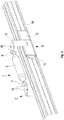
- FIG. 1 a preferred embodiment of a final storage device 1 has been shown.
- a guide rail section 14 which is used in the case of portable, guided in lateral guide rails door leaves, played.
- a force accumulator 2 is shown via connections 7 and 8.
- the connections 7, 8 have been designed, for example, as eyelets and engage in the connection 3 and the holder 11 interchangeable in holes 16 a.
- the energy storage device 2 is designed as a tension spring or as another element that can store energy in a Switzerlandbeetzschung.
- the stationary connection 3 is attached to the guide rail section 14 in a force-locking manner directly or via a rail section 15, the holder 11 is connected to an interchangeable and translationally changeable driver 9.
- the driver 9 has been shown as a slider 10 in a plastic version. Characterized in that the slider 10 has such a length, which goes beyond the width of the holder 11, a good guide within the guide rail portion 14 is achieved. Instead of the slider 10, it is also possible to use rollers or rolling elements here.
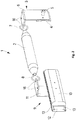
- the composition of the driver 9 is exemplified in an exemplary embodiment in the form of the slider 10 in a perspective view. Connected to the slider 10 is also a stop piece 12 is shown. To ensure proper guidance within the guide portion 14, located above and below between the slider 10 and the stopper 12 recesses 13 or grooves that are dimensionally matched to the thickness of the design of the guide rail portion 14. In particular, from this presentation of FIG. 2 It will be apparent that the end-of-line storage device 1 does not require a housing and, in addition to its ease of assembly, can also be produced cost-effectively.
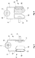
- FIG. 3 The side view of the end storage device 1, the FIG. 3 be removed. This makes it clear that the stationary connection 3, for example, on the right side consists of an angle 6. On the opposite left side, the bracket 11 has also been shown in an angular version. The holder 11 is removably attached to the driver 9.
- the use of the end storage device 1 with a guide rail section 14 and a rail section 15 is the FIG. 4 again.
- the angle 6 has been screwed in conjunction with a retaining element 4 and a fastening 5 on the rail section 15, which is located next to the guide rail section 14.
- the rail portion 15 is used for fixed attachment of the end storage device 1. By a connection, a clamping action between the rail portion 15 and the angle 6 is achieved. This makes it clear that the attachment point to the rail section 15 can be chosen freely and thus the can be adapted to local installation locations.
- On the opposite side of the guide rail portion 14 has been shown in a sectional view of the driver 9 in engagement within the guide rail portion 14.
- the shape of the guide rail used is independent of the design of the slider 9, because this can be adapted to the shape of the guide rail portion 14.
- the above-described end-of-line storage device 1 is preferably mounted on both sides of the guide rail sections 14 via existing rail sections 15.
- devices can preferably be mounted at the lateral ends of the door leaf, which cooperate with the driver 9 with the contact of the door leaf. Due to the separate rail section 15 parallel to the guide rail section 14, it is possible to carry out a stepless adjustment of the approach point with the driver 9.
Landscapes
- Engineering & Computer Science (AREA)
- Mechanical Engineering (AREA)
- Operating, Guiding And Securing Of Roll- Type Closing Members (AREA)
Applications Claiming Priority (1)
| Application Number | Priority Date | Filing Date | Title |
|---|---|---|---|
| DE102018108217.7A DE102018108217A1 (de) | 2018-04-06 | 2018-04-06 | Endlagenspeichervorrichtung sowie ein Tor mit einer Endlagenspeichervorrichtung |
Publications (1)
| Publication Number | Publication Date |
|---|---|
| EP3550100A1 true EP3550100A1 (fr) | 2019-10-09 |
Family
ID=66101977
Family Applications (1)
| Application Number | Title | Priority Date | Filing Date |
|---|---|---|---|
| EP19167628.7A Withdrawn EP3550100A1 (fr) | 2018-04-06 | 2019-04-05 | Dispositif doté d'un accumulateur de force en position finale ainsi que porte dotée d'un dispositif doté d'un accumulateur de force en position finale |
Country Status (2)
| Country | Link |
|---|---|
| EP (1) | EP3550100A1 (fr) |
| DE (1) | DE102018108217A1 (fr) |
Cited By (2)
| Publication number | Priority date | Publication date | Assignee | Title |
|---|---|---|---|---|
| EP3656958A1 (fr) | 2018-11-23 | 2020-05-27 | Alpha Deuren International BV | Entraînement auxiliaire pourvu de dispositif d'amortissement pour un battant de portail motorisée ainsi que portail, dont battant de portail est équipé d'un entraînement auxiliaire contenant un dispositif d'amortissement |
| EP3822443A1 (fr) | 2019-11-18 | 2021-05-19 | Alpha Deuren International BV | Entraînement auxiliaire pourvu de dispositif d'amortissement pour un vantail de portail mobile et portail pourvu d'un tel entraînement auxiliaire pourvu de dispositif d'amortissement |
Citations (5)
| Publication number | Priority date | Publication date | Assignee | Title |
|---|---|---|---|---|
| DE2027491A1 (de) | 1970-06-04 | 1971-12-16 | Kurz, Rudolf, 7918 Illertissen | Tor fur Hallen, Garagen oder dgl |
| EP0726378A1 (fr) * | 1995-02-13 | 1996-08-14 | Erich Dr.h.c. Döring | Porte, en particulier porte à sections relevables |
| DE19844031A1 (de) * | 1998-09-25 | 2000-03-30 | Hoklar Therm Tech Handel Gmbh | Einrichtung zum Bewegen eines zu öffnenden Schiebesegmentes eines Bautenbereiches |
| WO2007124576A1 (fr) * | 2006-04-27 | 2007-11-08 | Canimex Inc. | Kit de rallonge de porte-ressort |
| DE102015100617A1 (de) | 2015-01-16 | 2016-07-21 | Alpha Deuren International Bv | Torblatt |
-
2018
- 2018-04-06 DE DE102018108217.7A patent/DE102018108217A1/de not_active Ceased
-
2019
- 2019-04-05 EP EP19167628.7A patent/EP3550100A1/fr not_active Withdrawn
Patent Citations (5)
| Publication number | Priority date | Publication date | Assignee | Title |
|---|---|---|---|---|
| DE2027491A1 (de) | 1970-06-04 | 1971-12-16 | Kurz, Rudolf, 7918 Illertissen | Tor fur Hallen, Garagen oder dgl |
| EP0726378A1 (fr) * | 1995-02-13 | 1996-08-14 | Erich Dr.h.c. Döring | Porte, en particulier porte à sections relevables |
| DE19844031A1 (de) * | 1998-09-25 | 2000-03-30 | Hoklar Therm Tech Handel Gmbh | Einrichtung zum Bewegen eines zu öffnenden Schiebesegmentes eines Bautenbereiches |
| WO2007124576A1 (fr) * | 2006-04-27 | 2007-11-08 | Canimex Inc. | Kit de rallonge de porte-ressort |
| DE102015100617A1 (de) | 2015-01-16 | 2016-07-21 | Alpha Deuren International Bv | Torblatt |
Cited By (6)
| Publication number | Priority date | Publication date | Assignee | Title |
|---|---|---|---|---|
| EP3656958A1 (fr) | 2018-11-23 | 2020-05-27 | Alpha Deuren International BV | Entraînement auxiliaire pourvu de dispositif d'amortissement pour un battant de portail motorisée ainsi que portail, dont battant de portail est équipé d'un entraînement auxiliaire contenant un dispositif d'amortissement |
| DE102018129581A1 (de) * | 2018-11-23 | 2020-05-28 | Alpha Deuren International Bv | Hilfsantrieb für ein motorisch angetriebenes Torblatt, sowie Tor mit einem Hilfsantrieb |
| DE102018129581B4 (de) | 2018-11-23 | 2023-08-03 | Alpha Deuren International Bv | Hilfsantrieb für ein motorisch angetriebenes Torblatt, sowie Tor mit einem Hilfsantrieb |
| EP3822443A1 (fr) | 2019-11-18 | 2021-05-19 | Alpha Deuren International BV | Entraînement auxiliaire pourvu de dispositif d'amortissement pour un vantail de portail mobile et portail pourvu d'un tel entraînement auxiliaire pourvu de dispositif d'amortissement |
| DE102019131119A1 (de) * | 2019-11-18 | 2021-05-20 | Alpha Deuren International Bv | Hilfsantrieb mit Dämpfungseinrichtung für ein ortsveränderbares Torblatt |
| DE102019131119B4 (de) * | 2019-11-18 | 2025-07-03 | Alpha Deuren International Bv | Hilfsantrieb mit Dämpfungseinrichtung für ein ortsveränderbares Torblatt |
Also Published As
| Publication number | Publication date |
|---|---|
| DE102018108217A1 (de) | 2019-10-10 |
Similar Documents
| Publication | Publication Date | Title |
|---|---|---|
| DE102018123345B4 (de) | Antriebsvorrichtung für elektrische Türen | |
| DE202012002741U1 (de) | Beschlag für einen zumindest annähernd parallel abstellbaren und in dieser Parallelabstelllage horizontal verschiebbaren Flügel von Fenstern oder Türen | |
| DE102016202377A1 (de) | Beschlaganordnung zur Anbindung eines schieb- und kippbaren Flügels | |
| EP1317594A1 (fr) | Systeme d'ouverture de porte destine notamment a des vehicules | |
| DE102018108217A1 (de) | Endlagenspeichervorrichtung sowie ein Tor mit einer Endlagenspeichervorrichtung | |
| EP2840214A1 (fr) | Dispositif ferme-porte | |
| DE102004062167B4 (de) | Fensterheberanordnung | |
| EP3656958B1 (fr) | Entraînement auxiliaire pourvu de dispositif d'amortissement pour un battant de portail motorisée ainsi que portail, dont battant de portail est équipé d'un entraînement auxiliaire contenant un dispositif d'amortissement | |
| EP3045643B1 (fr) | Vantail de porte | |
| DE202011102484U1 (de) | Schließmechanismus für eine mit Kraftunterstützung schließende Schiebetüre | |
| DE202020104958U1 (de) | Schwenkschiebetür für ein Fahrzeug, sowie Drehsäule für eine Schwenkschiebetür | |
| DE202016007175U1 (de) | Vorrichtung zum Öffnen und Schließen eines Flügels | |
| DE202018101882U1 (de) | Endlagendämpfungsvorrichtung | |
| DE102008028598A1 (de) | Insektenschutztür | |
| DE102013212650C5 (de) | Vorrichtung zur Regelung der Schließfolge einer zweiflügeligen Drehtüranlage | |
| EP2450514A1 (fr) | Entraînement pour un battant de porte ou de fenêtre | |
| DE102021115147A1 (de) | Lageranordnung zur Lagerung einer Heckklappe eines Fahrzeugs an einer Fahrzeug-Karosserie und Fahrzeug mit einer derartigen Lageranordnung | |
| DE102014202797B3 (de) | Distanzhalter | |
| DE102013110485A1 (de) | Türgriffanordnung für ein Kraftfahrzeug | |
| DE102019131119B4 (de) | Hilfsantrieb mit Dämpfungseinrichtung für ein ortsveränderbares Torblatt | |
| DE102015100616B3 (de) | Sensorische Vorrichtung | |
| EP2674558B1 (fr) | Agencement d'actionnement de porte | |
| EP2039549B1 (fr) | Système de porte coulissante pivotante | |
| DE202008013553U1 (de) | Beschlag für einen Flügel von Fenstern oder Türen | |
| DE102008004996A1 (de) | Fahrzeugtür mit einem durch einen Motor betätigten Fensterheber |
Legal Events
| Date | Code | Title | Description |
|---|---|---|---|
| PUAI | Public reference made under article 153(3) epc to a published international application that has entered the european phase |
Free format text: ORIGINAL CODE: 0009012 |
|
| STAA | Information on the status of an ep patent application or granted ep patent |
Free format text: STATUS: THE APPLICATION HAS BEEN PUBLISHED |
|
| AK | Designated contracting states |
Kind code of ref document: A1 Designated state(s): AL AT BE BG CH CY CZ DE DK EE ES FI FR GB GR HR HU IE IS IT LI LT LU LV MC MK MT NL NO PL PT RO RS SE SI SK SM TR |
|
| AX | Request for extension of the european patent |
Extension state: BA ME |
|
| STAA | Information on the status of an ep patent application or granted ep patent |
Free format text: STATUS: REQUEST FOR EXAMINATION WAS MADE |
|
| 17P | Request for examination filed |
Effective date: 20200325 |
|
| RBV | Designated contracting states (corrected) |
Designated state(s): AL AT BE BG CH CY CZ DE DK EE ES FI FR GB GR HR HU IE IS IT LI LT LU LV MC MK MT NL NO PL PT RO RS SE SI SK SM TR |
|
| STAA | Information on the status of an ep patent application or granted ep patent |
Free format text: STATUS: EXAMINATION IS IN PROGRESS |
|
| 17Q | First examination report despatched |
Effective date: 20231025 |
|
| STAA | Information on the status of an ep patent application or granted ep patent |
Free format text: STATUS: THE APPLICATION IS DEEMED TO BE WITHDRAWN |
|
| 18D | Application deemed to be withdrawn |
Effective date: 20250708 |