EP3548937B1 - Optische komponente zur erzeugung eines lichteffekts - Google Patents
Optische komponente zur erzeugung eines lichteffekts Download PDFInfo
- Publication number
- EP3548937B1 EP3548937B1 EP17801479.1A EP17801479A EP3548937B1 EP 3548937 B1 EP3548937 B1 EP 3548937B1 EP 17801479 A EP17801479 A EP 17801479A EP 3548937 B1 EP3548937 B1 EP 3548937B1
- Authority
- EP
- European Patent Office
- Prior art keywords
- optical component
- region
- regions
- layer
- layers
- Prior art date
- Legal status (The legal status is an assumption and is not a legal conclusion. Google has not performed a legal analysis and makes no representation as to the accuracy of the status listed.)
- Active
Links
Images


Classifications
-
- F—MECHANICAL ENGINEERING; LIGHTING; HEATING; WEAPONS; BLASTING
- F21—LIGHTING
- F21V—FUNCTIONAL FEATURES OR DETAILS OF LIGHTING DEVICES OR SYSTEMS THEREOF; STRUCTURAL COMBINATIONS OF LIGHTING DEVICES WITH OTHER ARTICLES, NOT OTHERWISE PROVIDED FOR
- F21V3/00—Globes; Bowls; Cover glasses
- F21V3/02—Globes; Bowls; Cover glasses characterised by the shape
-
- B—PERFORMING OPERATIONS; TRANSPORTING
- B29—WORKING OF PLASTICS; WORKING OF SUBSTANCES IN A PLASTIC STATE IN GENERAL
- B29C—SHAPING OR JOINING OF PLASTICS; SHAPING OF MATERIAL IN A PLASTIC STATE, NOT OTHERWISE PROVIDED FOR; AFTER-TREATMENT OF THE SHAPED PRODUCTS, e.g. REPAIRING
- B29C64/00—Additive manufacturing, i.e. manufacturing of three-dimensional [3D] objects by additive deposition, additive agglomeration or additive layering, e.g. by 3D printing, stereolithography or selective laser sintering
- B29C64/10—Processes of additive manufacturing
- B29C64/106—Processes of additive manufacturing using only liquids or viscous materials, e.g. depositing a continuous bead of viscous material
- B29C64/118—Processes of additive manufacturing using only liquids or viscous materials, e.g. depositing a continuous bead of viscous material using filamentary material being melted, e.g. fused deposition modelling [FDM]
-
- G—PHYSICS
- G02—OPTICS
- G02B—OPTICAL ELEMENTS, SYSTEMS OR APPARATUS
- G02B5/00—Optical elements other than lenses
- G02B5/003—Light absorbing elements
-
- B—PERFORMING OPERATIONS; TRANSPORTING
- B33—ADDITIVE MANUFACTURING TECHNOLOGY
- B33Y—ADDITIVE MANUFACTURING, i.e. MANUFACTURING OF THREE-DIMENSIONAL [3-D] OBJECTS BY ADDITIVE DEPOSITION, ADDITIVE AGGLOMERATION OR ADDITIVE LAYERING, e.g. BY 3-D PRINTING, STEREOLITHOGRAPHY OR SELECTIVE LASER SINTERING
- B33Y80/00—Products made by additive manufacturing
-
- F—MECHANICAL ENGINEERING; LIGHTING; HEATING; WEAPONS; BLASTING
- F21—LIGHTING
- F21V—FUNCTIONAL FEATURES OR DETAILS OF LIGHTING DEVICES OR SYSTEMS THEREOF; STRUCTURAL COMBINATIONS OF LIGHTING DEVICES WITH OTHER ARTICLES, NOT OTHERWISE PROVIDED FOR
- F21V3/00—Globes; Bowls; Cover glasses
- F21V3/04—Globes; Bowls; Cover glasses characterised by materials, surface treatments or coatings
- F21V3/06—Globes; Bowls; Cover glasses characterised by materials, surface treatments or coatings characterised by the material
-
- G—PHYSICS
- G02—OPTICS
- G02B—OPTICAL ELEMENTS, SYSTEMS OR APPARATUS
- G02B2207/00—Coding scheme for general features or characteristics of optical elements and systems of subclass G02B, but not including elements and systems which would be classified in G02B6/00 and subgroups
- G02B2207/123—Optical louvre elements, e.g. for directional light blocking
Definitions
- the present invention relates to an optical component for generating a light effect.
- the present invention further relates to a luminaire including such an optical component, and to a method of manufacturing such an optical component.
- US 2015/0021628 A1 discloses a solid state light emitting device including one or more light affecting elements (e.g., of one or more light-transmissive, light-absorptive, light-reflective, and/or lumiphoric materials) formed on, over, or around at least one solid state light emitter, with the light affecting elements including multiple fused elements embodying plurality of dots, rods, or layers such as may be formed by three-dimensional (3-D) printing.
- Light affecting elements may be individually tailored to individual solid state light emitters, such as to yield different optical distributions for interactions between each specific emitter and its corresponding light affecting element.
- the present invention seeks to provide an optical component that can be manufactured in a cost-effective manner using 3-D printing techniques and is capable of generating an aesthetically pleasing visual effect.
- the present invention further seeks to provide a luminaire including such an optical component.
- the present invention further seeks to provide a method of manufacturing such an optical component.
- an optical component according to claim 1 According to a first aspect, there is provided an optical component according to claim 1.
- the above optical component comprises a plurality of layers, each layer comprising a transmissive portion (being at least one of the second and third regions) and a further portion (the first region) adjacent to the transmissive portion and having a lower transmissivity than the transmissive portion, wherein the portions are staggered such that the optical component comprises at least one transmissive region (referred to as the passage) that is formed by partially overlapping transmissive portions.
- the present invention is based on the realization that an optical component, or at least a part thereof, may be built up by partially overlapping, i.e. staggered, layers, thereby enabling the manufacture of the optical component using 3-D printing, wherein the further portions manipulate a portion of the luminous output generated by a light source or plurality of light sources positioned relative to the optical component, whereas the transmissive regions, e.g. transparent regions, which may be formed by a part of a transmissive portion or by partially overlapping parts of such transmissive portions allow for a further portion of the luminous output generated by the one or more light sources to pass through the optical component (relatively) unchanged.
- the transmissive regions e.g. transparent regions
- the optical component provides angularly-dependent light effects caused by the alternating pattern of further surrounding portions that manipulate part of the luminous output of the one or more light sources and the transmissive regions, which light effects may be perceived as dynamic light effects by an observer changing his or her position, i.e. viewing angle, relative to the optical component and therefore may be perceived as particularly interesting.
- Such an optical component may have any suitable shape, e.g. a planar shape in which a light source or plurality of light sources is hidden from direct view by the optical component, such as for example for a surface-mounted light source covered by the optical component.
- the optical component comprises an inner volume, and each layer envelopes part of said inner volume.
- each of the first, second and third regions may envelope part of said inner volume.
- each of the first, second and third regions may be proximal to the inner volume.
- the first, second and third regions may be alternately proximal to the inner volume to further manipulate the optical effect achieved with the optical component, either within the same layer or between subsequent layers of the stack.
- Such a structure may be readily achieved by certain 3-D printing techniques.
- the optical component may be formed in its entirety by the stack of layers, wherein next to the first region each layer also comprises at least one of the second and third regions.
- the optical component may comprise an alternating pattern of first parts and further parts, wherein only the first parts comprise the stack of layers as defined above, and wherein the further parts are isotropically transmissive, such that the optical component comprises first parts displaying angularly-dependent optical effects and further parts that are transmissive independent of viewing angle.
- This for example may provide an optical component that combines functional lighting by light passing through the further parts with dynamic lighting effects by light passing through the first parts.
- each of the first regions is located in between a second region and a third region in a direction perpendicular to the stacking direction, wherein each first region has a transmissivity that is lower than that of each of the adjacent second and third regions.
- each of the second and third regions is also referred to as "a region of higher transmissivity".
- the first regions are part of the layer stack.
- the layer stack further comprises a region of higher transmissivity, so at least one of the second and third regions is also part of the layer stack.
- the second and third regions may both be part of the layer stack.
- the other region eg. the third region simply refers to a region of the ambient surrounding the optical component, such as a region of air.
- the first regions terminate at one of the first and second wall surfaces, while the second region or the third region (depending on which of these is also part of the layer stack) may terminate at the other of the first and second wall surfaces.
- the layer stack only comprises one of the second and third regions, wherein each of the two regions comprised in the layer stack terminate at a wall surface, successive layers of the layer stack are staggered with respect to each other.
- Each first region has a defined width, wherein successive layers are staggered with respect to each other by a distance that is larger than the defined width of the first region.
- first region of each layer may terminate at one of the first and second wall surfaces and thereby define an edge of the layer.
- first region of each layer may be an intermediate region of the layer, located in between second and third regions that are both also part of the layer.
- the respective edges of the layers may have sharp corners or rounded corners.
- the shape of the corners of the edges may be chosen based on a desired optical function of the optical component as differently shaped corners will have a different interaction with incident light generated by the one or more light sources within the inner volume of the optical component.
- the first regions of the optical component are used to manipulate incident light such as to create a visible difference between the first regions and the transmissive passages of the optical component through which a light ray can pass through the wall without having to travel through the first region.
- Any suitable type of optical manipulation may be contemplated for this purpose.
- each first region may be individually selected from a coloured region, a reflective region, a diffuse region, an transmissive outer region surrounding a transmissive inner region having a different refractive index to the outer egion.
- the respective surrounding outer regions are the same.
- a luminaire comprising the optical component according to the first aspect.
- Such a luminaire which may further comprise one or more light sources, provides an aesthetically pleasing effect to an observer, which optical effect is particularly interesting due to the angular dependence of the created optical effect.
- a method of manufacturing the optical component according to the first aspect comprises the step of 3-D printing the plurality of layers with an extruder nozzle.
- the 3-D printing comprises forming an inner volume of the optical component by enveloping each layer around part of said inner volume.
- each first region and each of the second and/or third regions may envelope part of said inner volume.
- a region of higher transmissivity (the second or third region) may be proximal to the inner volume or the first region may be proximal to the inner volume.
- the 3-D printing comprises forming each layer such that in each layer the first region and a region of higher transmissivity (the second or third region) are alternately proximal to the inner volume. This for example may be achieved using dual nozzle printing techniques in which the nozzles are rotated (relative to each other) as is well-known per se.
- the 3-D printing comprises printing the first region and a region of higher transmissivity of each layer with an extruder nozzle having two nozzles.
- the optical component may be formed by rotating the substrate onto which the respective layers are printed although preferably the one or more extruder nozzles are rotated during the 3-D printing of a layer in order to form the layers.
- FIG. 1A shows the first wall surface 111 and the second wall surface 112.
- the first wall surface 111 faces inner volume 150 that is enclosed by the wall 110 of optical component 100, which has the form of a hollow circular cylinder.
- the first wall surface 111 and the second wall surface 112 are opposite each other in first direction 121, and parallel to each other in second direction 122, which is perpendicular to first direction 121.
- FIG. 1B shows a cross section of the wall 110, again illustrating the first wall surface 111 and the second wall surface 112, wherein the first wall surface 111 is opposite to the second wall surface 112 in the first direction 121.
- the cross section only shows one half of the optical component 100.
- FIG. 1B The middle view of FIG. 1B is the same cross section as illustrated in the upper view of FIG. 1B , but now shows the plurality of layers 130 that are stacked on top of each other in the second direction 122 perpendicular to the first direction 121.
- the second direction 122 is also referred to as "the stacking direction”.
- Each of the layers 130a-d of the plurality of layers 130 forms a closed structure that surrounds or envelopes a portion of the inner volume 150 of the optical component 100.
- This inner volume 150 may be used for positioning one or more light sources relative to the optical component 100.
- Each of the first regions 131a-d has a first edge surface 134a-d and a second edge surface 135a-d, both of which extend through the layer 130a-d in the second direction 122.
- the second edge surfaces 135a-d are opposite to the first edge surfaces 134a-d in the first direction 121.
- the first edge surfaces 134a-d are facing the first wall surface 111, and each of them is an interface with a second region 132a-d.
- the second edge surface 135a-d are facing the second wall surface 112, and each of them is an interface with a third region 133a-d.
- the first edge surface 134a-d is shifted with respect to the second edge surface of the next layer in the second direction 122.
- the layers 130a-d are stacked on top each other in such a way that the first regions 131a-d are staggered relative to each other, and non-overlapping in the stacking direction (direction 122).
- FIG. 1B again shows the stack of layers that is comprised in the wall, and the first, second, and third regions that are present in each of these layers.
- the reference numerals for the aforementioned features have been deliberately omitted from the lower view of FIG. 1B .
- This view now also shows the passages 140a-d that are present in the optical component 100, and that allow a light ray to pass through the wall of the optical component 100 without having to travel through the second regions 132a-d.
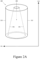
- FIG. 2A schematically depicts a perspective view of optical component 200
- FIG. 2B schematically depicts three views of the same cross section of the optical component 200.
- Fig. 2A shows the first wall surface 211 and the second wall surface 212.
- the first wall surface 211 faces inner volume 250 that is enclosed by the wall of optical component 200.
- the first wall surface 211 and the second wall surface 212 are opposite each other in the first direction 221.
- the second wall surface 212 is oriented parallel to the stacking direction (second direction 222), while the first wall surface 211 is inclined with respect to the stacking direction, so that the optical component 200 has the shape of a hollow circular cylinder with an inner diameter that decreases in the stacking direction.
- FIG. 2B The three views of FIG. 2B are similar to those already described in relation to FIG. 1B .
- the first regions 231a-d all have substantially the same dimensions, and the second regions 232a-d all have substantially the same dimensions.
- the second regions 232a-d terminate at the first wall surface 211, and the third regions 233a-d terminate at the second wall surface 212.
- the first edge surface 234a-d is shifted with respect to the second edge surface of the next layer in the second direction 222.
- the layers 230a-d are stacked on top each other in such a way that the first regions 231a-d are staggered relative to each other, and non-overlapping in the stacking direction (direction 122).
- FIG. 2B shows the passages 240a-d that are present in the optical component 200, and that allow a light ray to pass through the wall of the optical component 200 without having to travel through the first regions 231a-d.
- FIG. 3A schematically depicts a perspective view of optical component 300
- FIG. 3B schematically depicts three views of the same cross section of a optical component 300.
- Fig. 3A shows the first wall surface 311 and the second wall surface 312.
- the first wall surface 311 faces inner volume 350 that is enclosed by the wall of optical component 300.
- the first wall surface 311 and the second wall surface 312 are opposite each other in first direction 321.
- the second wall surface 312 is oriented parallel to the the first wall surface 211 while both are inclined with respect to the stacking direction.
- the optical component 300 has the shape of a hollow truncated cone.
- the first edge surface 334a-d is shifted with respect to the second edge surface of the next layer in the second direction 322.
- the layers 330a-d are stacked on top each other in such a way that the first regions 331a-d are staggered relative to each other, and non-overlapping in the stacking direction (direction 322).
- FIG. 3B shows the passages 340a-d that are present in the optical component 300, and that allow a light ray to pass through the wall of the optical component 300 without having to travel through the first regions 331a-d.
- FIG. 4 schematically depicts three views of the same cross section of optical component 400.
- the first regions 431a-d all have substantially the same dimensions, and the third regions 433a-d all have substantially the same dimensions.
- the first regions 431a-d terminate at the first wall surface 411, and the third regions 433a-d terminate at the second wall surface 412.
- the first regions 431a-d are not part of the layers 430a-d, and also not of the optical component 400 as a whole. Instead, the first regions 431a-d are regions of the ambient (air) that is present adjacent to the second wall surface 312.
- FIG. 4 shows the passages 440a-d that are present in the optical component 400, and that allow a light ray to pass through the wall of the optical component 400 without having to travel through the first regions 431a-d.
- the optical component 300 is formed of a plurality of partially overlapping layers 330a-d such that the layers 330a-d are staggered, thereby forming a stepped profile, here on the first wall surface 311 as well as on the second wall surface 312 of the optical component 300 although it should be understood that depending on the preferred shape, none of the first and second wall surfaces has a stepped profile (as is the case for optical component 100 illustrated in FIGS. 1A and 1B ), or a stepped profile may be formed on only one of the first and second wall surfaces (as is the case for optical component 200 illustrated in FIGS. 2A and 2B ).
- the staggering of the plurality of layers 300 may be readily achieved using 3-D printing techniques, in particular with fused deposition modelling (FDM) printers.
- FDM fused deposition modelling
- Such techniques make it possible to form particularly thin layers 330a-d, e.g. having a thickness of less than 2 mm, thereby ensuring that the details (the stepped profile) of the staggered layers 330a-d cannot be observed from a typical observation distance from the optical component 300 when in use, such as a distance of 1 m or more when the optical component 300 is used as a lampshade such as a pendant lamp shade or a lampshade mounted on a pole-based floor-mounted luminaire by way of non-limiting example.
- lampshade such as a pendant lamp shade or a lampshade mounted on a pole-based floor-mounted luminaire by way of non-limiting example.
- optical component 500 may be formed in its entirety of such staggered layers as described above in relation to FIGS. 3 and 4 .
- FIG. 5 An alternative is illustrated in FIG. 5 , wherein optical component 500 is shown that comprises an alternating pattern of first parts 550a-b built up by staggered layers as described in relation to FIGS. 3 and 4 , and second parts 560a-b, such as transparent parts, which may be formed in any suitable manner, e.g. as a single layer of a transparent polymer material.
- the first parts 550a-b may be used to create angularly-dependent optical effects as will be explained in more detail below whereas the second parts 560a-b do not exhibit such angularly-dependent optical effects.
- optical component 500 is to provide functional lighting in combination with dynamic lighting effects, in which the functional lighting is provided by the second parts 560a-b and the dynamic lighting effect is provided by the first parts 550a-b, in particular when an observer of the optical component 500 changes his or her orientation relative to the optical component 500.
- the optical component not according to the invention may form an open structure, e.g. a planar or curved structure that is at least partially built up by the stack of layers as described hereinbefore.
- the optical component may be used as a cover or the like over a surface-mounted, e.g. wall-mounted or ceiling-mounted light source arrangement to create the desired optical effect to an observer looking at the optical component.
- each of the layers forms a closed structure that surrounds or envelopes a portion of an inner volume of the optical component, which inner volume may be used for positioning one or more light sources relative to the optical component, e.g. within the inner volume or outside the inner volume, such that the optical effect may be observed by looking into the inner volume.
- Any suitable type of light source may be used for this purpose, such as an incandescent or fluorescent light source or a solid state light source such as one or more LEDs, which may be white light LEDs, coloured LEDs or combinations thereof.
- the closed structure formed by each of the layers may have any suitable shape, e.g.
- the layers are staggered such that the staggered layers form a truncated conical optical component, which for example may be useful if the optical component is to be used as a lampshade such as a pendant lamp shape.
- the layers may have different shapes and not each layer may have the same shape, i.e. different layers may have different shapes, such that the optical component may have any suitable shape.
- At least some of the layers, and preferably each of the layers, comprises a region of higher transmissivity that is a closed structure surrounding part of an inner volume of the optical component and forms part of the layer and the first region adjacent to the region of higher transmissivity that is a closed structure surrounding part of the inner volume of the optical component and forms another part of the layer.
- FIG. 6 shows a vertical cross-section of optical component 600, similar to optical component 300 as illustrated in FIG. 3 .
- the layers 630a-b are staggered such that the first regions 631a-b of adjacent layers 630a-b are non-overlapping.
- each first region 631a-b has a defined width W1, being the distance between first edge surface 634a-b and second edge surface 635a-b, and a distance D between the second edge surface 635a-b and a second edge surface of a first region of an adjacent layer, wherein the distance D exceeds the defined width W1, as can be seen in the lower view of FIG. 6 .
- each pair of neighbouring first regions 631a-b are spatially separated by a transmissive passage, which transmissive passage may be formed by part of a second region 632a-b or by a stack of parts of second regions 632a-b of layers 630a-b staggered on top of each other. Consequently, a pattern of first regions 631a-b is formed in the optical component 600, which first regions 631a-b are separated by transmissive passages formed by partially overlapping second regions 632a-b.
- each layer 630a-b has a first region 631a-b and an adjacent second region 632a-b, i.e. the first region 631a-b and the second region 632a-b are arranged next to each other in a direction perpendicular to the direction wherein the layers 630a-b are staggered on top of each other.
- the layers are provided such that the a region of higher transmissivty (in these case the second regions) are proximal to the inner volume of the optical component.
- the regions of higher transmissivity are distal to the inner volume of the optical component, i.e. that the first regions are proximal to the inner volume.
- the layers do not need to be continuous in the sense that the same portion of the layer is proximal to the inner volume over the full length of the layer.
- FIG. 7 shows optical component 700, having a wall 710 with first wall surface 711 and second wall surface 712.
- Each layer 730a-b has a first region 731a-b located between a second region 732a-b and a third region 733a-b, wherein each of the second region 732a-b and the third region 733a-b has a higher transmissivity than the first region 731a-b.
- the first region 731a-b has a first edge surface 734a-b facing the first wall surface 711 and a second edge surface 735a-b facing the second wall surface 712.
- the lower view of FIG. 7 shows a cross section through layer 730a in a direction perpendicular to the stacking direction.
- the cross section of the layer 730a has the shape of a ring.
- the cross section of the first region 731a also has the shape of a ring, but of a smaller diameter and width, and positioned off-center compared to the layer 730a.
- the first region 731 terminates at the first wall surface 711, while at the opposite side of the layer 730a it terminates at the second surface 712.
- the second region 732a terminates at the first wall surface 711 and the third region 733a terminates at the second wall surface 712.
- each layer 730a-b comprises a first portion in which the second region 712a-d is proximal to the first wall surface, and a second portion in which the first region 731a-b is proximal to the first wall surface.
- the first edge surface 734a is shifted with respect to the second edge surface 735b of the next layer 730b in the stacking direction, thereby creating a passage through which a light ray can pass through the wall 710 without having to travel through the first region 731a.
- a configuration as illustrated in FIG. 7 may be readily achieved by moving a fixed arrangement of a pair of nozzles (for printing the first regions 731a-b and the regions of higher transmissivity simultaneously) in a circular motion substantially perpendicularly to a surface on which the respective portions are deposited, thereby forming two interleaving circles in which the cross sections as shown on the left and right in the upper and middle views of FIG. 7 are separated by cross-over regions.
- each layer has a lower transmissivity than the second and third regions of such a layer in order to create a different interaction with light generated by a light source within or outside the inner volume.
- FIG. 6 schematically depicts part of an optical component 600 according to an embodiment in a cross-sectional view, wherein a light source 660 is positioned in the inner volume of the optical component 600.
- the light source 660 typically generates light rays under different angles, here symbolically depicted by light rays 661-663, from which it can be seen that rays emitted under different angles have a different interaction with the optical component 600.
- light rays in an angular range including light ray 661 as well as light rays in an angular range including light ray 663 are incident on a first region 631a-b and will therefore be manipulated differently compared to light rays in an angular range including light ray 662, which may travel substantially unimpeded through the second region 632a. Consequently, the optical component 600 generates an angularly-dependent light effect, which can change as a result of a viewing angle under which the optical component 600 is observed, such that the optical component 600 may create what may be perceived as a dynamic optical effect that is aesthetically pleasing and/or of interest.
- the regions of higher transmissivity may be transparent, with the respective first regions being less transparent than the surrounding regions of higher transmissivity.
- the first regions may be partially or totally absorbent or reflective. More specifically, the first regions may be coloured, reflective, diffuse or emissive. Alternatively, the first regions may be transmissive but have a different refractive index to the regions of higher transmissivity. It should be understood that not all first regions have to be the same, it is equally feasible that different first regions have different optical properties, for example to create more intricate or complex optical effects with the optical component.
- each of the layers has two regions that are optically different with respect to each other, one being more transmissive than the other.
- the difference in the optical properties of the regions may be in terms of scattering characteristics (scattering angle), reflection characteristics, refractive index and luminescence as well as in terms of absorption and colour characteristics.
- a region of higher transmissivity comprises a material that, when having a thickness of 1 mm, transmits more than 5% and preferably transmits more than 20% of the light falling onto it.
- regions of higher transmissivity may be transparent, may have a coloured appearance, may be luminescent and/or may be reflective in some embodiments.
- each layer 630a-b has a thickness T, which preferably is below 2 mm as previously explained, and a total width formed by the combined width of the second region 632a-b having a width W2 and the first region 631a-b having a width W1.
- each layer 630a-b of the optical component 600 has the same thickness T and total width, which when combined with each layer 630a-b staggering another layer 630a-b by the same degree yields a regular pattern of first regions 63 1a-b separated by passages formed by partially overlapping second regions 632a-b, which passages allow light rays to pass through the wall of the optical component 600 without having to travel through a first region 63 1a-b.
- each layer 630a-b has relatively sharp edges at their opposite ends, but the shape of these edges may be tailored in accordance with the desired optical effect to be created.
- opposing ends of the respective layers may have rounded edges.
- the layers including the first regions and the regions of higher transmissivity may be manufactured and assembled in any suitable manner.
- the optical component may be manufactured using a 3-D printing technique such as fused deposition modeling (FDM) printing.
- FDM printers use a thermoplastic filament, which is heated to its melting point and then extruded, layer by layer, to create a three dimensional object.
- FDM printers are relatively fast, low cost and can be used for printing complicated 3D objects.
- Such printers may be used for printing various shapes using various polymers, as is well-known per se.
- the printer is controlled using a print command file generated by computer aided design (CAD) software specifying the 3-D shape of the optical component, and this controls how the filament is processed.
- CAD computer aided design
- FIG. 8 is used to explain the operation of a fused deposition modeling printer 800.
- a filament 810 is passed between a pair of driver wheels 812 to a printer head 814 having an output nozzle 816.
- a layer 818 of the material is deposited while in a high viscosity liquid state, which then cools and cures.
- a 3D structure may be built up as a sequence of layer patterns, e.g. the staggered layers to form the optical component 900, as is schematically depicted in FIG. 9 , in which the optical component 900 is manufactured by stacking layers on top of each other from the base to the top of the cone, i.e.
- optical component 900 in a bottom-up manner, owing to the shape of the optical component 900 although it should be understood that this is by way of non-limiting example only as it is for example equally feasible to manufacture the optical component in a top-down manner for most 3-D shapes of the optical component.
- the optical component may be printed using an extruder nozzle 816 having two nozzles for producing two separate layers 818, e.g. two layers or a region of higher transmissivity and the first region of a single layer.
- the optical component may be printed using an extruder nozzle 816 having a first feeder comprising a first material for forming a region of higher transmissivity and a second feeder comprising a second material for forming a first region.
- a support on which the optical component is formed may be rotated in order to form the optical component or alternatively the extruded nozzle 816 may be rotated during the 3-D printing of a layer of the optical component to form the 3-D shape of the optical component.
- any suitable material may be used for forming the respective first regions, second regions and third regions.
- these may be materials suitable for use in a 3-D printing process, e.g. polymers that may be extruded in an FDM printing process.
- the optical properties of these portions may be tuned by the addition of further materials.
- a colourant such as a dye or a pigment may be added to a polymer
- scattering particles may be added to a polymer
- a reflective first region a reflective coating such as a metal coating may be printed on a surface such as an inner surface of the first region facing the inner volume of the optical component
- a luminescent compound may be added to the polymer, and so on.
- the layers of the optical component may be made of the same combination of materials whereas in alternative embodiments different layers of the optical component may be made of different materials or combinations of materials.
- different layers may have different first regions and/or may have different regions of higher transmissivity, such that the desired optical properties of the optical component may be tuned by selecting such different materials for different layers.
- the optical component according to embodiments of the present invention may be used as part of a luminaire such as a ceiling pendant, a floor-mounted luminaire in which the optical component is positioned on top of a (vertical) pole, and so on.
- a luminaire may further comprise one or more light sources, e.g. point light sources such as LEDs or diffuse light sources such as incandescent, halogen or fluorescent light sources.
- the light sources may be individually controllable to further enhance the optical effect that can be achieved by guiding the light generated with the light sources through the optical component.
- the one or more light sources in the luminaire may be dimmable.
- the optical component may be used as a lampshade of the luminaire although it should be understood that embodiments of the optical component are not limited to such use and may be used in any suitable manner.
- the one or more light sources may be hidden from view by the optical component in normal use.
- the one or more light sources may be positioned within an inner volume of the optical component or outside an inner volume of the optical component, for example if the desired optical effect is to be created within the inner volume.
- a plurality of light sources may be arranged on a substrate or carrier in a pattern such that the optical component may be positioned inside the pattern, and wherein the light sources are arranged to couple light into the optical component.
- FIGS. 10 and 11 Some example embodiments of luminaires are schematically depicted in FIGS. 10 and 11 .
- the optical component 1000 defines a light exit window of a luminaire 10 in which a light source 30 is mounted proximal to a reflector 20, e.g. a parabolic reflector or the like, for redirecting light emitted by the light source 30 to the light exit window, i.e. the optical component 1000.
- a reflector 20 e.g. a parabolic reflector or the like
- other optical components may be combined with the optical component 1000 in such a luminaire 1.
- FIG. 11 schematically depicts example pendant luminaires 11a and 11b, respectively, in which the optical components 1110 and 1120 have a free-form shape with an inner volume 1111 and 1121, respectively, to illustrate the fact that the optical component according to the present invention may have any suitable shape.
- Light sources 31a and 31b are located in the inner volumes 1111 and 1121, respectively.
Landscapes
- Physics & Mathematics (AREA)
- Engineering & Computer Science (AREA)
- Optics & Photonics (AREA)
- Chemical & Material Sciences (AREA)
- Materials Engineering (AREA)
- General Engineering & Computer Science (AREA)
- General Physics & Mathematics (AREA)
- Manufacturing & Machinery (AREA)
- Mechanical Engineering (AREA)
- Non-Portable Lighting Devices Or Systems Thereof (AREA)
- Optical Elements Other Than Lenses (AREA)
- Illuminated Signs And Luminous Advertising (AREA)
Claims (11)
- Optische Komponente (100), die eine Wand (110) mit einer ersten Wandoberfläche (111) und einer zweiten Wandoberfläche (112) aufweist, wobei die zweite Wandoberfläche (112) gegenüber der ersten Wandoberfläche (111) in einer ersten Richtung (121) ist, die Wand (110) umfassend eine Vielzahl von Schichten (130), die in einer zweiten Richtung (122) übereinandergestapelt sind, die zu der ersten Richtung (121) senkrecht ist,wobei die optische Komponente (100) ein Innenvolumen (150) umfasst, und wobei jede Schicht (130a-d) Teil des Innenvolumens (150) umhüllt,dadurch gekennzeichnet, dass jede Schicht (130a-d) der Vielzahl von Schichten (130) einen ersten Bereich (131a-d) mit einer ersten Kantenoberfläche (134a-d) und einer gegenüberliegenden zweiten Kantenoberfläche (135a-d) aufweist, die sich beide durch die Schicht (130a-d) in die zweite Richtung (122) erstrecken, wobei die erste Kantenoberfläche (134a-d) eine Schnittstelle zwischen dem ersten Bereich (131a-d) und einem zweiten Bereich (132a-d) ist und die zweite Kantenoberfläche (135a-d) eine Schnittstelle zwischen dem ersten Bereich (131a-d) und einem dritten Bereich (133a-d) ist, wobei der erste Bereich (131a-d) eine niedrigere Durchlässigkeit aufweist als jeder des zweiten Bereichs (131a-d) und des dritten Bereichs (133a-d), wobei jede Schicht ebenso mindestens einen des zweiten und des dritten Bereichs umfasst,wobei jeder erste Bereich (631a-b) eine definierte Breite (W1) aufweist, die ein Abstand zwischen der ersten Kantenoberfläche (134a-d) und der zweiten Kantenoberfläche (135a-d) ist, undwobei sich aufeinanderfolgende Schichten (630a-b) teilweise derart überlappen, dass die ersten Bereiche (631a-b) angrenzender Schichten (630a-b) sich nicht überlappen.
- Optische Komponente (100) nach Anspruch 1, wobei jeder der ersten Bereiche (131a-d), der zweiten Bereiche (132a-d) und der dritten Bereiche (133a-d) Teil des Innenvolumens (150) umhüllen.
- Optische Komponente (700) nach einem der Ansprüche 1 bis 2, wobei jede Schicht (730a-b) einen ersten Abschnitt, in dem der zweite Bereich (732a-b) zu der ersten Wandoberfläche (711) proximal ist, und einen zweiten Abschnitt umfasst, in dem der erste Bereich (731a-b) zu der ersten Wandoberfläche (711) proximal ist.
- Optische Komponente (500) nach einem der Ansprüche 1 bis 3, umfassend ein alternierendes Muster erster Teile (550a-b) einschließlich der Vielzahl von Schichten (130) und weiterer durchlässiger Teile (560a-b).
- Optische Komponente (100) nach einem der Ansprüche 1 bis 4, wobei jeder erste Bereich (131a-d) aus einem farbigen Abschnitt, einem reflektierenden Abschnitt, einem diffusen Abschnitt, einem emittierenden Abschnitt und einem transparenten Abschnitt einzeln ausgewählt ist, der einen anderen Brechungsindex als der zweite Bereich (132a-d) und der dritte Bereich (133a-d) aufweist.
- Optische Komponente (100) nach Anspruch 5, wobei die jeweiligen ersten Bereiche (131a-d) gleich sind.
- Optische Komponente (100) nach einem der Ansprüche 1 bis 6, wobei verschiedene Schichten (130a-d) aus verschiedenen Materialien bestehen und/oder verschiedene Abmessungen aufweisen.
- Leuchte (10), umfassend die optische Komponente (20) nach einem der Ansprüche 1 bis 7.
- Leuchte (11a; 11b) nach Anspruch 8, die Leuchte (11a; 11b) ferner umfassend eine Lichtquelle (31a; 31b), die innerhalb oder außerhalb des Innenvolumens (1111; 1121) positioniert ist.
- Verfahren zum Herstellen der optischen Komponente (100) nach einem der Ansprüche 1 bis 7, wobei das Verfahren den Schritt eines 3D-Druckens der Vielzahl von Schichten (130) mit einem 3D-Drucker (800) umfasst, der eine Extruderdüse (816) aufweist, und wobei das 3D-Drucken ein Bilden des Innenvolumens (150) der optischen Komponente (100) durch Umhüllen jeder Schicht (130a-d) um Teil des Innenvolumens (150) umfasst.
- Verfahren nach Anspruch 10, wobei das 3D-Drucken das Bilden jeder Schicht (730a-b) derart umfasst, dass jede Schicht (730a-b) einen ersten Abschnitt, in dem der zweite Bereich (732a-b) zu der ersten Wandoberfläche (711) proximal ist, und einen zweiten Abschnitt umfasst, in dem der erste Bereich (731a-b) zu der ersten Wandoberfläche (711) proximal ist.
Applications Claiming Priority (2)
| Application Number | Priority Date | Filing Date | Title |
|---|---|---|---|
| EP16201589 | 2016-12-01 | ||
| PCT/EP2017/080354 WO2018099818A2 (en) | 2016-12-01 | 2017-11-24 | Optical component for generating a light effect |
Publications (2)
| Publication Number | Publication Date |
|---|---|
| EP3548937A2 EP3548937A2 (de) | 2019-10-09 |
| EP3548937B1 true EP3548937B1 (de) | 2024-09-18 |
Family
ID=57517697
Family Applications (1)
| Application Number | Title | Priority Date | Filing Date |
|---|---|---|---|
| EP17801479.1A Active EP3548937B1 (de) | 2016-12-01 | 2017-11-24 | Optische komponente zur erzeugung eines lichteffekts |
Country Status (5)
| Country | Link |
|---|---|
| US (1) | US10724706B2 (de) |
| EP (1) | EP3548937B1 (de) |
| JP (1) | JP7086071B2 (de) |
| CN (1) | CN110023793B (de) |
| WO (1) | WO2018099818A2 (de) |
Families Citing this family (8)
| Publication number | Priority date | Publication date | Assignee | Title |
|---|---|---|---|---|
| US12427714B2 (en) | 2018-10-19 | 2025-09-30 | National Research Council Of Canada | Functionalized product fabricated from a resin comprising a functional component and a polymeric resin, and method of making the same |
| JP7156022B2 (ja) * | 2018-12-28 | 2022-10-19 | セイコーエプソン株式会社 | 三次元造形物の製造方法および三次元造形装置 |
| WO2021044260A1 (en) | 2019-09-03 | 2021-03-11 | National Research Council Of Canada | 3d printed graded refractive index device |
| ES2986798T3 (es) * | 2020-03-05 | 2024-11-12 | Signify Holding Bv | Artículo en 3D con capas interpenetrantes producidas por impresión de varios materiales |
| EP3882003A1 (de) * | 2020-03-16 | 2021-09-22 | Signify Holding B.V. | 3d drucksache mit oberfläche mit öffnung |
| JP7163546B2 (ja) * | 2020-11-27 | 2022-11-01 | 東芝情報システム株式会社 | 空気質表示装置 |
| ES3031685T3 (en) | 2021-08-16 | 2025-07-10 | Signify Holding Bv | A lighting device, luminaire, and method manufacturing |
| US11835213B2 (en) | 2021-08-19 | 2023-12-05 | Matthew Hartley | Lighting fixtures with improved lighting components |
Family Cites Families (25)
| Publication number | Priority date | Publication date | Assignee | Title |
|---|---|---|---|---|
| GB713737A (en) | 1950-09-05 | 1954-08-18 | Edward Gustav Elton | Improvements in or relating to illumination devices |
| DE4236563A1 (de) * | 1992-10-29 | 1994-05-05 | Basf Magnetics Gmbh | Anti-Kopier-Film oder -Schicht |
| JPH0741341A (ja) * | 1993-07-28 | 1995-02-10 | Asahi Glass Co Ltd | 熱線反射複層構成体 |
| JPH11306838A (ja) * | 1998-04-27 | 1999-11-05 | Toshiba Tec Corp | 照明器具カバー |
| JP2000048618A (ja) | 1998-07-29 | 2000-02-18 | Casio Comput Co Ltd | 照明パネルおよびそれを用いた表示装置 |
| DE19922973C2 (de) * | 1999-05-19 | 2003-02-06 | Armin Schwab | Lichtdurchlässige Scheibenanordnung |
| JP4134462B2 (ja) | 1999-10-28 | 2008-08-20 | 株式会社デンソー | レーダ装置,調整方法,調整システム |
| US6398370B1 (en) | 2000-11-15 | 2002-06-04 | 3M Innovative Properties Company | Light control device |
| DE10246256A1 (de) | 2002-10-02 | 2004-04-22 | Semperlux Ag - Lichttechnische Werke - | Außenleuchte mit Abblendeinrichtung |
| JP2004199937A (ja) | 2002-12-17 | 2004-07-15 | Matsushita Electric Works Ltd | 照明用カバーおよびこの照明用カバーを用いた照明器具 |
| EP2390555B1 (de) | 2009-01-20 | 2017-10-11 | Panasonic Intellectual Property Management Co., Ltd. | Beleuchtungsgerät |
| JP2010169883A (ja) | 2009-01-22 | 2010-08-05 | Kyoto Univ | 遮光体 |
| CN102307724B (zh) * | 2009-02-06 | 2015-05-13 | 3M创新有限公司 | 光控膜和多层光学膜叠堆 |
| GB2480227A (en) * | 2010-03-01 | 2011-11-16 | Rue De Int Ltd | Optical security device with spaced microlines |
| JP6045818B2 (ja) | 2011-07-15 | 2016-12-14 | 株式会社東芝 | 照明装置 |
| CN103649625B (zh) | 2011-07-20 | 2016-06-08 | 皇家飞利浦有限公司 | 用于提供天窗外观的光学元件、照明系统和照明器 |
| US9248623B2 (en) | 2011-10-14 | 2016-02-02 | Makerbot Industries, Llc | Grayscale rendering in 3D printing |
| US9353932B2 (en) | 2013-03-13 | 2016-05-31 | Palo Alto Research Center Incorporated | LED light bulb with structural support |
| US9099575B2 (en) | 2013-07-16 | 2015-08-04 | Cree, Inc. | Solid state lighting devices and fabrication methods including deposited light-affecting elements |
| CN203560773U (zh) | 2013-10-23 | 2014-04-23 | 四川农业大学 | 竹木台灯 |
| US20150109674A1 (en) * | 2013-10-23 | 2015-04-23 | Ronald Steven Cok | Imprinted micro-louver structure |
| US10005126B2 (en) * | 2014-03-19 | 2018-06-26 | Autodesk, Inc. | Systems and methods for improved 3D printing |
| CN106716002B (zh) | 2014-05-21 | 2020-08-25 | 飞利浦灯具控股公司 | 装饰性led集成照明器 |
| US9927090B2 (en) | 2015-02-03 | 2018-03-27 | John Clifton Cobb, III | Profile-shaped articles |
| US20170217103A1 (en) | 2016-01-29 | 2017-08-03 | Massachusetts Institute Of Technology | Techniques for color contoning in additive fabrication and related systems and methods |
-
2017
- 2017-11-24 EP EP17801479.1A patent/EP3548937B1/de active Active
- 2017-11-24 US US16/462,657 patent/US10724706B2/en active Active
- 2017-11-24 CN CN201780074488.4A patent/CN110023793B/zh active Active
- 2017-11-24 JP JP2019529153A patent/JP7086071B2/ja active Active
- 2017-11-24 WO PCT/EP2017/080354 patent/WO2018099818A2/en not_active Ceased
Also Published As
| Publication number | Publication date |
|---|---|
| EP3548937A2 (de) | 2019-10-09 |
| JP7086071B2 (ja) | 2022-06-17 |
| CN110023793A (zh) | 2019-07-16 |
| US10724706B2 (en) | 2020-07-28 |
| WO2018099818A2 (en) | 2018-06-07 |
| CN110023793B (zh) | 2021-10-12 |
| US20190277475A1 (en) | 2019-09-12 |
| JP2020513587A (ja) | 2020-05-14 |
| WO2018099818A3 (en) | 2018-12-20 |
Similar Documents
| Publication | Publication Date | Title |
|---|---|---|
| EP3548937B1 (de) | Optische komponente zur erzeugung eines lichteffekts | |
| CN111132842B (zh) | 用于产生光效果的光学组件 | |
| CN107709869B (zh) | 具有可定制的光束形状、光束颜色和颜色均一性的led射灯 | |
| CN109414875B (zh) | 3d打印反射器及其制造方法 | |
| CN106796016B (zh) | 使用有微观小面的箔的可调谐日光体验 | |
| CN108884983B (zh) | 具有闪烁效果的照明装置 | |
| JP2018535125A (ja) | 3d印刷による光学構成要素の製造方法、光学構成要素、及び照明デバイス | |
| JP2003293336A (ja) | 視線誘導照明装置 | |
| EP4126506B1 (de) | Verfahren zur herstellung und 3d-gedruckten objekts, mit einem schrumpfschlauch überzogen | |
| CN111936787B (zh) | 装饰性光源掩蔽 | |
| CN112639358B (zh) | 反射器和用于形成反射器的起始片材 | |
| WO2025056458A1 (en) | A led filament lamp showing a flame effect |
Legal Events
| Date | Code | Title | Description |
|---|---|---|---|
| STAA | Information on the status of an ep patent application or granted ep patent |
Free format text: STATUS: UNKNOWN |
|
| STAA | Information on the status of an ep patent application or granted ep patent |
Free format text: STATUS: THE INTERNATIONAL PUBLICATION HAS BEEN MADE |
|
| PUAI | Public reference made under article 153(3) epc to a published international application that has entered the european phase |
Free format text: ORIGINAL CODE: 0009012 |
|
| STAA | Information on the status of an ep patent application or granted ep patent |
Free format text: STATUS: REQUEST FOR EXAMINATION WAS MADE |
|
| 17P | Request for examination filed |
Effective date: 20190701 |
|
| AK | Designated contracting states |
Kind code of ref document: A2 Designated state(s): AL AT BE BG CH CY CZ DE DK EE ES FI FR GB GR HR HU IE IS IT LI LT LU LV MC MK MT NL NO PL PT RO RS SE SI SK SM TR |
|
| AX | Request for extension of the european patent |
Extension state: BA ME |
|
| DAV | Request for validation of the european patent (deleted) | ||
| DAX | Request for extension of the european patent (deleted) | ||
| STAA | Information on the status of an ep patent application or granted ep patent |
Free format text: STATUS: EXAMINATION IS IN PROGRESS |
|
| 17Q | First examination report despatched |
Effective date: 20201104 |
|
| R17C | First examination report despatched (corrected) |
Effective date: 20201104 |
|
| GRAP | Despatch of communication of intention to grant a patent |
Free format text: ORIGINAL CODE: EPIDOSNIGR1 |
|
| STAA | Information on the status of an ep patent application or granted ep patent |
Free format text: STATUS: GRANT OF PATENT IS INTENDED |
|
| RIC1 | Information provided on ipc code assigned before grant |
Ipc: F21V 11/02 20060101ALI20240315BHEP Ipc: G02B 5/00 20060101AFI20240315BHEP |
|
| RIC1 | Information provided on ipc code assigned before grant |
Ipc: F21V 3/02 20060101ALI20240404BHEP Ipc: F21V 11/02 20060101ALI20240404BHEP Ipc: G02B 5/00 20060101AFI20240404BHEP |
|
| INTG | Intention to grant announced |
Effective date: 20240419 |
|
| GRAS | Grant fee paid |
Free format text: ORIGINAL CODE: EPIDOSNIGR3 |
|
| GRAA | (expected) grant |
Free format text: ORIGINAL CODE: 0009210 |
|
| STAA | Information on the status of an ep patent application or granted ep patent |
Free format text: STATUS: THE PATENT HAS BEEN GRANTED |
|
| AK | Designated contracting states |
Kind code of ref document: B1 Designated state(s): AL AT BE BG CH CY CZ DE DK EE ES FI FR GB GR HR HU IE IS IT LI LT LU LV MC MK MT NL NO PL PT RO RS SE SI SK SM TR |
|
| P01 | Opt-out of the competence of the unified patent court (upc) registered |
Free format text: CASE NUMBER: APP_46672/2024 Effective date: 20240812 |
|
| REG | Reference to a national code |
Ref country code: GB Ref legal event code: FG4D |
|
| REG | Reference to a national code |
Ref country code: CH Ref legal event code: EP |
|
| REG | Reference to a national code |
Ref country code: DE Ref legal event code: R096 Ref document number: 602017084936 Country of ref document: DE |
|
| REG | Reference to a national code |
Ref country code: IE Ref legal event code: FG4D |
|
| REG | Reference to a national code |
Ref country code: LT Ref legal event code: MG9D |
|
| PG25 | Lapsed in a contracting state [announced via postgrant information from national office to epo] |
Ref country code: NO Free format text: LAPSE BECAUSE OF FAILURE TO SUBMIT A TRANSLATION OF THE DESCRIPTION OR TO PAY THE FEE WITHIN THE PRESCRIBED TIME-LIMIT Effective date: 20241218 |
|
| PG25 | Lapsed in a contracting state [announced via postgrant information from national office to epo] |
Ref country code: GR Free format text: LAPSE BECAUSE OF FAILURE TO SUBMIT A TRANSLATION OF THE DESCRIPTION OR TO PAY THE FEE WITHIN THE PRESCRIBED TIME-LIMIT Effective date: 20241219 Ref country code: FI Free format text: LAPSE BECAUSE OF FAILURE TO SUBMIT A TRANSLATION OF THE DESCRIPTION OR TO PAY THE FEE WITHIN THE PRESCRIBED TIME-LIMIT Effective date: 20240918 |
|
| PG25 | Lapsed in a contracting state [announced via postgrant information from national office to epo] |
Ref country code: BG Free format text: LAPSE BECAUSE OF FAILURE TO SUBMIT A TRANSLATION OF THE DESCRIPTION OR TO PAY THE FEE WITHIN THE PRESCRIBED TIME-LIMIT Effective date: 20240918 |
|
| PG25 | Lapsed in a contracting state [announced via postgrant information from national office to epo] |
Ref country code: LV Free format text: LAPSE BECAUSE OF FAILURE TO SUBMIT A TRANSLATION OF THE DESCRIPTION OR TO PAY THE FEE WITHIN THE PRESCRIBED TIME-LIMIT Effective date: 20240918 |
|
| PG25 | Lapsed in a contracting state [announced via postgrant information from national office to epo] |
Ref country code: HR Free format text: LAPSE BECAUSE OF FAILURE TO SUBMIT A TRANSLATION OF THE DESCRIPTION OR TO PAY THE FEE WITHIN THE PRESCRIBED TIME-LIMIT Effective date: 20240918 |
|
| REG | Reference to a national code |
Ref country code: NL Ref legal event code: MP Effective date: 20240918 |
|
| PG25 | Lapsed in a contracting state [announced via postgrant information from national office to epo] |
Ref country code: RS Free format text: LAPSE BECAUSE OF FAILURE TO SUBMIT A TRANSLATION OF THE DESCRIPTION OR TO PAY THE FEE WITHIN THE PRESCRIBED TIME-LIMIT Effective date: 20241218 |
|
| PG25 | Lapsed in a contracting state [announced via postgrant information from national office to epo] |
Ref country code: RS Free format text: LAPSE BECAUSE OF FAILURE TO SUBMIT A TRANSLATION OF THE DESCRIPTION OR TO PAY THE FEE WITHIN THE PRESCRIBED TIME-LIMIT Effective date: 20241218 Ref country code: NO Free format text: LAPSE BECAUSE OF FAILURE TO SUBMIT A TRANSLATION OF THE DESCRIPTION OR TO PAY THE FEE WITHIN THE PRESCRIBED TIME-LIMIT Effective date: 20241218 Ref country code: LV Free format text: LAPSE BECAUSE OF FAILURE TO SUBMIT A TRANSLATION OF THE DESCRIPTION OR TO PAY THE FEE WITHIN THE PRESCRIBED TIME-LIMIT Effective date: 20240918 Ref country code: HR Free format text: LAPSE BECAUSE OF FAILURE TO SUBMIT A TRANSLATION OF THE DESCRIPTION OR TO PAY THE FEE WITHIN THE PRESCRIBED TIME-LIMIT Effective date: 20240918 Ref country code: GR Free format text: LAPSE BECAUSE OF FAILURE TO SUBMIT A TRANSLATION OF THE DESCRIPTION OR TO PAY THE FEE WITHIN THE PRESCRIBED TIME-LIMIT Effective date: 20241219 Ref country code: FI Free format text: LAPSE BECAUSE OF FAILURE TO SUBMIT A TRANSLATION OF THE DESCRIPTION OR TO PAY THE FEE WITHIN THE PRESCRIBED TIME-LIMIT Effective date: 20240918 Ref country code: BG Free format text: LAPSE BECAUSE OF FAILURE TO SUBMIT A TRANSLATION OF THE DESCRIPTION OR TO PAY THE FEE WITHIN THE PRESCRIBED TIME-LIMIT Effective date: 20240918 |
|
| REG | Reference to a national code |
Ref country code: AT Ref legal event code: MK05 Ref document number: 1725172 Country of ref document: AT Kind code of ref document: T Effective date: 20240918 |
|
| PG25 | Lapsed in a contracting state [announced via postgrant information from national office to epo] |
Ref country code: NL Free format text: LAPSE BECAUSE OF FAILURE TO SUBMIT A TRANSLATION OF THE DESCRIPTION OR TO PAY THE FEE WITHIN THE PRESCRIBED TIME-LIMIT Effective date: 20240918 |
|
| PG25 | Lapsed in a contracting state [announced via postgrant information from national office to epo] |
Ref country code: PT Free format text: LAPSE BECAUSE OF FAILURE TO SUBMIT A TRANSLATION OF THE DESCRIPTION OR TO PAY THE FEE WITHIN THE PRESCRIBED TIME-LIMIT Effective date: 20250120 Ref country code: IS Free format text: LAPSE BECAUSE OF FAILURE TO SUBMIT A TRANSLATION OF THE DESCRIPTION OR TO PAY THE FEE WITHIN THE PRESCRIBED TIME-LIMIT Effective date: 20250118 |
|
| PGFP | Annual fee paid to national office [announced via postgrant information from national office to epo] |
Ref country code: DE Payment date: 20250129 Year of fee payment: 8 |
|
| PG25 | Lapsed in a contracting state [announced via postgrant information from national office to epo] |
Ref country code: SM Free format text: LAPSE BECAUSE OF FAILURE TO SUBMIT A TRANSLATION OF THE DESCRIPTION OR TO PAY THE FEE WITHIN THE PRESCRIBED TIME-LIMIT Effective date: 20240918 Ref country code: RO Free format text: LAPSE BECAUSE OF FAILURE TO SUBMIT A TRANSLATION OF THE DESCRIPTION OR TO PAY THE FEE WITHIN THE PRESCRIBED TIME-LIMIT Effective date: 20240918 |
|
| PG25 | Lapsed in a contracting state [announced via postgrant information from national office to epo] |
Ref country code: ES Free format text: LAPSE BECAUSE OF FAILURE TO SUBMIT A TRANSLATION OF THE DESCRIPTION OR TO PAY THE FEE WITHIN THE PRESCRIBED TIME-LIMIT Effective date: 20240918 |
|
| PG25 | Lapsed in a contracting state [announced via postgrant information from national office to epo] |
Ref country code: AT Free format text: LAPSE BECAUSE OF FAILURE TO SUBMIT A TRANSLATION OF THE DESCRIPTION OR TO PAY THE FEE WITHIN THE PRESCRIBED TIME-LIMIT Effective date: 20240918 Ref country code: EE Free format text: LAPSE BECAUSE OF FAILURE TO SUBMIT A TRANSLATION OF THE DESCRIPTION OR TO PAY THE FEE WITHIN THE PRESCRIBED TIME-LIMIT Effective date: 20240918 |
|
| PG25 | Lapsed in a contracting state [announced via postgrant information from national office to epo] |
Ref country code: PL Free format text: LAPSE BECAUSE OF FAILURE TO SUBMIT A TRANSLATION OF THE DESCRIPTION OR TO PAY THE FEE WITHIN THE PRESCRIBED TIME-LIMIT Effective date: 20240918 Ref country code: CZ Free format text: LAPSE BECAUSE OF FAILURE TO SUBMIT A TRANSLATION OF THE DESCRIPTION OR TO PAY THE FEE WITHIN THE PRESCRIBED TIME-LIMIT Effective date: 20240918 |
|
| PG25 | Lapsed in a contracting state [announced via postgrant information from national office to epo] |
Ref country code: IT Free format text: LAPSE BECAUSE OF FAILURE TO SUBMIT A TRANSLATION OF THE DESCRIPTION OR TO PAY THE FEE WITHIN THE PRESCRIBED TIME-LIMIT Effective date: 20240918 Ref country code: SK Free format text: LAPSE BECAUSE OF FAILURE TO SUBMIT A TRANSLATION OF THE DESCRIPTION OR TO PAY THE FEE WITHIN THE PRESCRIBED TIME-LIMIT Effective date: 20240918 |
|
| REG | Reference to a national code |
Ref country code: DE Ref legal event code: R097 Ref document number: 602017084936 Country of ref document: DE |
|
| REG | Reference to a national code |
Ref country code: CH Ref legal event code: PL |
|
| PG25 | Lapsed in a contracting state [announced via postgrant information from national office to epo] |
Ref country code: MC Free format text: LAPSE BECAUSE OF FAILURE TO SUBMIT A TRANSLATION OF THE DESCRIPTION OR TO PAY THE FEE WITHIN THE PRESCRIBED TIME-LIMIT Effective date: 20240918 |
|
| PG25 | Lapsed in a contracting state [announced via postgrant information from national office to epo] |
Ref country code: DK Free format text: LAPSE BECAUSE OF FAILURE TO SUBMIT A TRANSLATION OF THE DESCRIPTION OR TO PAY THE FEE WITHIN THE PRESCRIBED TIME-LIMIT Effective date: 20240918 |
|
| PG25 | Lapsed in a contracting state [announced via postgrant information from national office to epo] |
Ref country code: LU Free format text: LAPSE BECAUSE OF NON-PAYMENT OF DUE FEES Effective date: 20241124 |
|
| REG | Reference to a national code |
Ref country code: CH Ref legal event code: PL |
|
| PG25 | Lapsed in a contracting state [announced via postgrant information from national office to epo] |
Ref country code: CH Free format text: LAPSE BECAUSE OF NON-PAYMENT OF DUE FEES Effective date: 20241130 |
|
| PLBE | No opposition filed within time limit |
Free format text: ORIGINAL CODE: 0009261 |
|
| STAA | Information on the status of an ep patent application or granted ep patent |
Free format text: STATUS: NO OPPOSITION FILED WITHIN TIME LIMIT |
|
| 26N | No opposition filed |
Effective date: 20250619 |
|
| REG | Reference to a national code |
Ref country code: BE Ref legal event code: MM Effective date: 20241130 |
|
| PG25 | Lapsed in a contracting state [announced via postgrant information from national office to epo] |
Ref country code: SE Free format text: LAPSE BECAUSE OF FAILURE TO SUBMIT A TRANSLATION OF THE DESCRIPTION OR TO PAY THE FEE WITHIN THE PRESCRIBED TIME-LIMIT Effective date: 20240918 |
|
| PG25 | Lapsed in a contracting state [announced via postgrant information from national office to epo] |
Ref country code: BE Free format text: LAPSE BECAUSE OF NON-PAYMENT OF DUE FEES Effective date: 20241130 |
|
| PG25 | Lapsed in a contracting state [announced via postgrant information from national office to epo] |
Ref country code: IE Free format text: LAPSE BECAUSE OF NON-PAYMENT OF DUE FEES Effective date: 20241124 |
|
| PGFP | Annual fee paid to national office [announced via postgrant information from national office to epo] |
Ref country code: GB Payment date: 20251125 Year of fee payment: 9 |
|
| PGFP | Annual fee paid to national office [announced via postgrant information from national office to epo] |
Ref country code: FR Payment date: 20251124 Year of fee payment: 9 |